EP4059746B1 - Air conditioning apparatus and ventilation system and - Google Patents
Air conditioning apparatus and ventilation system and Download PDFInfo
- Publication number
- EP4059746B1 EP4059746B1 EP22162675.7A EP22162675A EP4059746B1 EP 4059746 B1 EP4059746 B1 EP 4059746B1 EP 22162675 A EP22162675 A EP 22162675A EP 4059746 B1 EP4059746 B1 EP 4059746B1
- Authority
- EP
- European Patent Office
- Prior art keywords
- air
- air valve
- vent pipe
- vehicle
- interior space
- Prior art date
- Legal status (The legal status is an assumption and is not a legal conclusion. Google has not performed a legal analysis and makes no representation as to the accuracy of the status listed.)
- Active
Links
Images




Classifications
-
- B—PERFORMING OPERATIONS; TRANSPORTING
- B60—VEHICLES IN GENERAL
- B60H—ARRANGEMENTS OF HEATING, COOLING, VENTILATING OR OTHER AIR-TREATING DEVICES SPECIALLY ADAPTED FOR PASSENGER OR GOODS SPACES OF VEHICLES
- B60H1/00—Heating, cooling or ventilating devices
- B60H1/24—Ventilating devices where the heating or cooling is irrelevant
- B60H1/248—Air-extractors, air-evacuation from the vehicle interior
-
- B—PERFORMING OPERATIONS; TRANSPORTING
- B60—VEHICLES IN GENERAL
- B60H—ARRANGEMENTS OF HEATING, COOLING, VENTILATING OR OTHER AIR-TREATING DEVICES SPECIALLY ADAPTED FOR PASSENGER OR GOODS SPACES OF VEHICLES
- B60H1/00—Heating, cooling or ventilating devices
- B60H1/00007—Combined heating, ventilating, or cooling devices
- B60H1/00021—Air flow details of HVAC devices
- B60H1/00028—Constructional lay-out of the devices in the vehicle
-
- B—PERFORMING OPERATIONS; TRANSPORTING
- B60—VEHICLES IN GENERAL
- B60H—ARRANGEMENTS OF HEATING, COOLING, VENTILATING OR OTHER AIR-TREATING DEVICES SPECIALLY ADAPTED FOR PASSENGER OR GOODS SPACES OF VEHICLES
- B60H1/00—Heating, cooling or ventilating devices
- B60H1/00007—Combined heating, ventilating, or cooling devices
- B60H1/00021—Air flow details of HVAC devices
- B60H1/00035—Air flow details of HVAC devices for sending an air stream of uniform temperature into the passenger compartment
- B60H1/0005—Air flow details of HVAC devices for sending an air stream of uniform temperature into the passenger compartment the air being firstly cooled and subsequently heated or vice versa
-
- B—PERFORMING OPERATIONS; TRANSPORTING
- B60—VEHICLES IN GENERAL
- B60H—ARRANGEMENTS OF HEATING, COOLING, VENTILATING OR OTHER AIR-TREATING DEVICES SPECIALLY ADAPTED FOR PASSENGER OR GOODS SPACES OF VEHICLES
- B60H1/00—Heating, cooling or ventilating devices
- B60H1/00007—Combined heating, ventilating, or cooling devices
- B60H1/00207—Combined heating, ventilating, or cooling devices characterised by the position of the HVAC devices with respect to the passenger compartment
-
- B—PERFORMING OPERATIONS; TRANSPORTING
- B60—VEHICLES IN GENERAL
- B60H—ARRANGEMENTS OF HEATING, COOLING, VENTILATING OR OTHER AIR-TREATING DEVICES SPECIALLY ADAPTED FOR PASSENGER OR GOODS SPACES OF VEHICLES
- B60H1/00—Heating, cooling or ventilating devices
- B60H1/00457—Ventilation unit, e.g. combined with a radiator
-
- B—PERFORMING OPERATIONS; TRANSPORTING
- B60—VEHICLES IN GENERAL
- B60H—ARRANGEMENTS OF HEATING, COOLING, VENTILATING OR OTHER AIR-TREATING DEVICES SPECIALLY ADAPTED FOR PASSENGER OR GOODS SPACES OF VEHICLES
- B60H1/00—Heating, cooling or ventilating devices
- B60H1/00507—Details, e.g. mounting arrangements, desaeration devices
- B60H1/00557—Details of ducts or cables
- B60H1/00564—Details of ducts or cables of air ducts
-
- B—PERFORMING OPERATIONS; TRANSPORTING
- B60—VEHICLES IN GENERAL
- B60H—ARRANGEMENTS OF HEATING, COOLING, VENTILATING OR OTHER AIR-TREATING DEVICES SPECIALLY ADAPTED FOR PASSENGER OR GOODS SPACES OF VEHICLES
- B60H1/00—Heating, cooling or ventilating devices
- B60H1/00642—Control systems or circuits; Control members or indication devices for heating, cooling or ventilating devices
- B60H1/00735—Control systems or circuits characterised by their input, i.e. by the detection, measurement or calculation of particular conditions, e.g. signal treatment, dynamic models
- B60H1/00742—Control systems or circuits characterised by their input, i.e. by the detection, measurement or calculation of particular conditions, e.g. signal treatment, dynamic models by detection of the vehicle occupants' presence; by detection of conditions relating to the body of occupants, e.g. using radiant heat detectors
-
- B—PERFORMING OPERATIONS; TRANSPORTING
- B60—VEHICLES IN GENERAL
- B60H—ARRANGEMENTS OF HEATING, COOLING, VENTILATING OR OTHER AIR-TREATING DEVICES SPECIALLY ADAPTED FOR PASSENGER OR GOODS SPACES OF VEHICLES
- B60H1/00—Heating, cooling or ventilating devices
- B60H1/00642—Control systems or circuits; Control members or indication devices for heating, cooling or ventilating devices
- B60H1/00735—Control systems or circuits characterised by their input, i.e. by the detection, measurement or calculation of particular conditions, e.g. signal treatment, dynamic models
- B60H1/008—Control systems or circuits characterised by their input, i.e. by the detection, measurement or calculation of particular conditions, e.g. signal treatment, dynamic models the input being air quality
-
- B—PERFORMING OPERATIONS; TRANSPORTING
- B60—VEHICLES IN GENERAL
- B60H—ARRANGEMENTS OF HEATING, COOLING, VENTILATING OR OTHER AIR-TREATING DEVICES SPECIALLY ADAPTED FOR PASSENGER OR GOODS SPACES OF VEHICLES
- B60H1/00—Heating, cooling or ventilating devices
- B60H1/00642—Control systems or circuits; Control members or indication devices for heating, cooling or ventilating devices
- B60H1/00814—Control systems or circuits characterised by their output, for controlling particular components of the heating, cooling or ventilating installation
- B60H1/00821—Control systems or circuits characterised by their output, for controlling particular components of the heating, cooling or ventilating installation the components being ventilating, air admitting or air distributing devices
-
- B—PERFORMING OPERATIONS; TRANSPORTING
- B60—VEHICLES IN GENERAL
- B60H—ARRANGEMENTS OF HEATING, COOLING, VENTILATING OR OTHER AIR-TREATING DEVICES SPECIALLY ADAPTED FOR PASSENGER OR GOODS SPACES OF VEHICLES
- B60H1/00—Heating, cooling or ventilating devices
- B60H1/00642—Control systems or circuits; Control members or indication devices for heating, cooling or ventilating devices
- B60H1/00814—Control systems or circuits characterised by their output, for controlling particular components of the heating, cooling or ventilating installation
- B60H1/00821—Control systems or circuits characterised by their output, for controlling particular components of the heating, cooling or ventilating installation the components being ventilating, air admitting or air distributing devices
- B60H1/00835—Damper doors, e.g. position control
-
- B—PERFORMING OPERATIONS; TRANSPORTING
- B60—VEHICLES IN GENERAL
- B60H—ARRANGEMENTS OF HEATING, COOLING, VENTILATING OR OTHER AIR-TREATING DEVICES SPECIALLY ADAPTED FOR PASSENGER OR GOODS SPACES OF VEHICLES
- B60H1/00—Heating, cooling or ventilating devices
- B60H1/00642—Control systems or circuits; Control members or indication devices for heating, cooling or ventilating devices
- B60H1/00985—Control systems or circuits characterised by display or indicating devices, e.g. voice simulators
-
- B—PERFORMING OPERATIONS; TRANSPORTING
- B60—VEHICLES IN GENERAL
- B60H—ARRANGEMENTS OF HEATING, COOLING, VENTILATING OR OTHER AIR-TREATING DEVICES SPECIALLY ADAPTED FOR PASSENGER OR GOODS SPACES OF VEHICLES
- B60H1/00—Heating, cooling or ventilating devices
- B60H1/22—Heating, cooling or ventilating devices the heat source being other than the propulsion plant
- B60H1/2215—Heating, cooling or ventilating devices the heat source being other than the propulsion plant the heat being derived from electric heaters
- B60H1/2225—Heating, cooling or ventilating devices the heat source being other than the propulsion plant the heat being derived from electric heaters arrangements of electric heaters for heating air
-
- B—PERFORMING OPERATIONS; TRANSPORTING
- B60—VEHICLES IN GENERAL
- B60H—ARRANGEMENTS OF HEATING, COOLING, VENTILATING OR OTHER AIR-TREATING DEVICES SPECIALLY ADAPTED FOR PASSENGER OR GOODS SPACES OF VEHICLES
- B60H1/00—Heating, cooling or ventilating devices
- B60H1/24—Ventilating devices where the heating or cooling is irrelevant
- B60H1/241—Ventilating devices where the heating or cooling is irrelevant characterised by the location of ventilation devices in the vehicle
- B60H1/242—Ventilating devices where the heating or cooling is irrelevant characterised by the location of ventilation devices in the vehicle located in the front area
-
- B—PERFORMING OPERATIONS; TRANSPORTING
- B60—VEHICLES IN GENERAL
- B60H—ARRANGEMENTS OF HEATING, COOLING, VENTILATING OR OTHER AIR-TREATING DEVICES SPECIALLY ADAPTED FOR PASSENGER OR GOODS SPACES OF VEHICLES
- B60H1/00—Heating, cooling or ventilating devices
- B60H1/24—Ventilating devices where the heating or cooling is irrelevant
- B60H1/26—Ventilating openings in vehicle exterior; Ducts for conveying ventilating air
- B60H1/28—Ventilating openings in vehicle exterior; Ducts for conveying ventilating air the openings being situated directly in front of vehicle front window
-
- B—PERFORMING OPERATIONS; TRANSPORTING
- B60—VEHICLES IN GENERAL
- B60H—ARRANGEMENTS OF HEATING, COOLING, VENTILATING OR OTHER AIR-TREATING DEVICES SPECIALLY ADAPTED FOR PASSENGER OR GOODS SPACES OF VEHICLES
- B60H3/00—Other air-treating devices
- B60H3/06—Filtering
- B60H3/0608—Filter arrangements in the air stream
-
- B—PERFORMING OPERATIONS; TRANSPORTING
- B60—VEHICLES IN GENERAL
- B60H—ARRANGEMENTS OF HEATING, COOLING, VENTILATING OR OTHER AIR-TREATING DEVICES SPECIALLY ADAPTED FOR PASSENGER OR GOODS SPACES OF VEHICLES
- B60H1/00—Heating, cooling or ventilating devices
- B60H1/00007—Combined heating, ventilating, or cooling devices
- B60H1/00021—Air flow details of HVAC devices
- B60H2001/00078—Assembling, manufacturing or layout details
- B60H2001/00099—Assembling, manufacturing or layout details comprising additional ventilating means
-
- B—PERFORMING OPERATIONS; TRANSPORTING
- B60—VEHICLES IN GENERAL
- B60H—ARRANGEMENTS OF HEATING, COOLING, VENTILATING OR OTHER AIR-TREATING DEVICES SPECIALLY ADAPTED FOR PASSENGER OR GOODS SPACES OF VEHICLES
- B60H1/00—Heating, cooling or ventilating devices
- B60H1/00007—Combined heating, ventilating, or cooling devices
- B60H1/00021—Air flow details of HVAC devices
- B60H2001/0015—Temperature regulation
- B60H2001/00178—Temperature regulation comprising an air passage from the HVAC box to the exterior of the cabin
-
- B—PERFORMING OPERATIONS; TRANSPORTING
- B60—VEHICLES IN GENERAL
- B60H—ARRANGEMENTS OF HEATING, COOLING, VENTILATING OR OTHER AIR-TREATING DEVICES SPECIALLY ADAPTED FOR PASSENGER OR GOODS SPACES OF VEHICLES
- B60H1/00—Heating, cooling or ventilating devices
- B60H1/00007—Combined heating, ventilating, or cooling devices
- B60H1/00021—Air flow details of HVAC devices
- B60H2001/00185—Distribution of conditionned air
- B60H2001/00192—Distribution of conditionned air to left and right part of passenger compartment
-
- B—PERFORMING OPERATIONS; TRANSPORTING
- B60—VEHICLES IN GENERAL
- B60H—ARRANGEMENTS OF HEATING, COOLING, VENTILATING OR OTHER AIR-TREATING DEVICES SPECIALLY ADAPTED FOR PASSENGER OR GOODS SPACES OF VEHICLES
- B60H1/00—Heating, cooling or ventilating devices
- B60H1/00007—Combined heating, ventilating, or cooling devices
- B60H1/00207—Combined heating, ventilating, or cooling devices characterised by the position of the HVAC devices with respect to the passenger compartment
- B60H2001/00214—Devices in front of the passenger compartment
Definitions
- the invention relates to an air conditioning (A/C) apparatus with a ventilation system.
- A/C air conditioning
- car windows of the vehicle are usually closed when an air conditioning (A/C) system of the vehicle is in operation.
- A/C air conditioning
- closed car windows lead to poor ventilation and reduced oxygen concentration in the passenger compartment, which is unsafe, especially after prolonged operation of the AC system. Under such unsafe condition, a driver may be easily fatigued, find it difficult to concentrate, and be prone to making mistakes and getting in a traffic accident.
- an object of the invention is to provide an air conditioning (A/C) apparatus with a ventilation system that can alleviate at least one of the drawbacks of the prior art.
- Document KR 2001 0065954 A describes an air conditioning apparatus for motor vehicle, in which an additional unit for ingress of outdoor air is arranged so as to increase the volume of outdoor air ingress during ventilation.
- the ventilation system is adapted to be used in a vehicle.
- the vehicle includes a vehicle body that defines an interior space.
- the ventilation system includes a vent pipe and a fan.
- the vent pipe is adapted to be disposed on the vehicle body, and has an outside communicating end via which the vent pipe is adapted to communicate with the outside of the vehicle body, and an inside communicating end via which said vent pipe is adapted to communicate with the interior space.
- the fan is disposed in the vent pipe, and is configured to be activated to produce airflow from the outside communicating end to the inside communicating end.
- the A/C apparatus is adapted to be used in a vehicle.
- the vehicle includes a vehicle body that defines an interior space.
- the A/C apparatus includes an A/C system and a ventilation system.
- the A/C system includes an air duct, an A/C device and a blower.
- the air duct When mounted in the vehicle, the air duct has an external inlet end via which the air duct is adapted to communicate with the outside of the vehicle, and a plurality of outlet ends via which the air duct is adapted to communicate with the interior space of the vehicle.
- the A/C device is disposed in the air duct, and is configured to be controlled to regulate temperature of air flowing through said A/C device.
- the blower is disposed in the air duct, and is configured to be controlled to drive air to flow from the external inlet end through the A/C device to said plurality of outlet ends.
- the ventilation system includes a vent pipe and a fan.
- vent pipe extends along the air duct in the air duct.
- the vent pipe has an outside communicating end and at least one inside communicating end.
- the outside communicating end is exposed out of the air duct.
- the vent pipe is adapted to communicate with the outside of the vehicle via the outside communicating end.
- Said at least one inside communicating end is disposed at one of said plurality of outlet ends of the air duct and communicates with said one of said plurality of outlet ends.
- the vent pipe is adapted to communicate with the interior space of the vehicle via said at least one inside communicating end.
- the fan is disposed in the vent pipe, and is configured to be activated to produce airflow from the outside communicating end to said at least one inside communicating end.
- the ventilation system 100 is adapted to be used in a vehicle 900.
- the vehicle 900 may be implemented by one of a sedan, a sedan wagon, a van, a hatchback, a sport utility vehicle (SUV), a multipurpose vehicle, a sports car, a convertible, a bus and so on, but is not limited thereto.
- SUV sport utility vehicle
- the vehicle 900 includes a vehicle body 901 that defines an interior space 902 (i.e., a passenger compartment), and an air conditioning (A/C) system 903 disposed on the vehicle body 901.
- A/C air conditioning
- the A/C system 903 includes a plurality of air intakes 904 (only one is shown in the drawings), and a plurality of air outlets 905.
- the A/C system 903 is configured to be controlled to operate in one of an internal circulation mode and an external circulation mode.
- the A/C system 903 When operating in the internal circulation mode, the A/C system 903 is configured to draw air from the interior space 902 via the air intakes 904, to process the air thus drawn by filtering the air and adjusting temperature of the air, and to then expel the air thus processed via the air outlets 905 back to the interior space 902.
- the A/C system 903 When operating in the external circulation mode, the A/C system 903 is configured to draw air from the outside of the vehicle 900, to process the air thus drawn by filtering the air and adjusting temperature of the air, and to expel the air thus processed via the air outlets 905 to the interior space 902.
- the ventilation system 100 includes a vent pipe 2, a fan 31, a filter 32, a cooler 33, a heater 34, an air valve 4, a controller 51, an oxygen sensor 52 and a timer 53.
- the controller 51 is adapted to be disposed partially in the interior space (902) of the vehicle body 901, and is electrically connected to the fan 31, the filter 32, the cooler 33, the air valve 4, the oxygen sensor 52 and the timer 53.
- the vent pipe 2 is adapted to be disposed on the vehicle body 901, and includes a main pipe 24 and a plurality of side pipes 20.
- the vent pipe 2 has an outside communicating end 21 via which the vent pipe 2 is adapted to communicate with the outside of the vehicle body 901, and a plurality of inside communicating ends 22 via which the vent pipe 2 is adapted to communicate with the interior space 902.
- the main pipe 24 defines the outside communicating end 21.
- the side pipes 20 are connected to the main pipe 24 and respectively define the inside communicating ends 22.
- the inside communicating ends 22 may be positioned respectively beside the air outlets 905 near a driver seat and a front passenger seat as shown in Figure 3 , and accordingly air flowing from the vent pipe 2 into the interior space 902 can rapidly mix with air flowing out of the air outlets 905 and spread throughout the interior space 902.
- the inside communicating ends 22 may be positioned respectively beside the air intakes 904 (see Figure 4 , where only one inside communicating end 22 and one air intake 904 are shown). In this way, air flowing from the vent pipe 2 into the interior space 902 can be immediately drawn by the A/C system 903 via the air intakes 904 for further processing, and can then be expelled via the air outlets 905 back to the interior space 902.
- each of the inside communicating ends 22 may be positioned at any location that is exposed to the interior space 902.
- the number of the inside communicating ends 22 is not limited to what is disclosed herein and may vary in other embodiments.
- the vent pipe 2 has only one inside communicating end 22.
- the fan 31, the filter 32, the cooler 33 and the heater 34 are disposed in the main pipe 24 of the vent pipe 2, and are arranged in an extension direction of the main pipe 24.
- the fan 31 is configured to be activated to produce airflow from the outside communicating end 21 to each of the inside communicating ends 22, so air flowing from the outside of the vehicle body 901 into the interior space 902 can be processed by the filter 32, the cooler 33 and the heater 34 in the vent pipe 2.
- the controller 51 is configured to control the fan 31 to rotate in one of a forward direction to produce airflow from the outside communicating end 21 to each of the inside communicating ends 22, and a reverse direction to produce airflow from each of the inside communicating ends 22 to the outside communicating end 21.
- the ventilation system 100 supplies air from the outside of the vehicle 900 to the interior space 902.
- the ventilation system 100 draws air from the interior space 902 to the outside of the vehicle 900.
- the ventilation system 100 further includes an air quality sensor (not shown).
- the air quality sensor is disposed in the interior space 902, and is configured to measure the air quality within the interior space 902.
- the controller 51 is configured to determine, based on results of measurement made by the air quality sensor, whether the air quality within the interior space 902 is poor (e.g., particles of toxic substance or cigarette smoke appear in the interior space 902). When it is determined that the air quality within the interior space 902 is poor, the controller 51 is configured to control the fan 31 to rotate in the reverse direction to draw air from the interior space 902 to the outside of the vehicle 900.
- the controller 51 will be instantly activated when the vehicle 900 is unlocked by a remote control. Then, the controller 51 is configured to control the fan 31 to rotate in the reverse direction for a predetermined time period (e.g., five minutes) so as to refresh air in the interior space 902.
- a predetermined time period e.g., five minutes
- the filter 32 is configured to filter air passing through the filter 32 in the vent pipe 2 so as to remove dust particles or hazardous substance from the air.
- the cooler 33 is configured to be controlled by the controller 51 to cool air passing through the cooler 33 in the vent pipe 2.
- the heater 34 is configured to be controlled by the controller 51 to heat air passing through the heater 34 in the vent pipe 2.
- the air valve 4 is disposed at the outside communicating end 21 of the vent pipe 2.
- the controller 51 is configured to control the air valve 4 to switch between an open state where the air valve 4 allows the vent pipe 2 to communicate with the outside of the vehicle body 901, and a closed state where the air valve 4 disallows the vent pipe 2 to communicate with the outside of the vehicle body 901.
- the closed state of the air valve 4 is indicated by sloid lines
- the open state of the air valve 4 is indicated by dashed lines.
- the air valve 4 may be implemented by an electric valve, but is not limited thereto. Since implementation of the air valve 4 has been well known to one skilled in the relevant art, detailed explanation of the same is omitted herein for the sake of brevity.
- the ventilation system 100 does not include the air valve 4.
- the oxygen sensor 52 is adapted to be disposed in the interior space 902 of the vehicle body 901.
- the oxygen sensor 52 is configured to measure oxygen concentration in the interior space 902 to generate a concentration indication signal, and to output the concentration indication signal to the controller 51.
- the controller 51 is operable in one of a triggered ventilation mode and a regular ventilation mode.
- the controller 51 is adapted to be further electrically connected to the A/C system 903, and to be notified by the A/C system 903 that the A/C system 903 operates in which one of the internal circulation mode and the external circulation mode.
- the controller 51 includes a control panel 511 that is disposed in the interior space 902, and a processing unit (not shown) that is configured to implement the operations of the controller 51 described herein.
- the control panel 511 is configured to be operated by a user to activate the cooler 33 and the heater 34, independently, and to make the controller 51 operate in the triggered ventilation mode or the regular ventilation mode.
- the controller 51 is configured to activate the oxygen sensor 52 to measure oxygen concentration in the interior space 902 when the A/C system 903 notifies the controller 51 that the A/C system 903 operates in the internal circulation mode.
- the controller 51 is further configured to determine whether the oxygen concentration is lower than a low-oxygen-concentration threshold based on the concentration indication signal.
- the controller 51 is configured to control the timer 53 to time a preset time period (e.g., five minutes), and during the preset time period, to control the air valve 4 to switch to the open state and to activate the fan 31 to rotate in the forward direction so as to produce airflow from the outside of the vehicle 900 to the interior space 902.
- a preset time period e.g., five minutes
- the controller 51 is configured to control the air valve 4 to switch to the closed state and to stop the fan 31. In this way, whenever the oxygen concentration falls to an abnormal level, the oxygen concentration in the interior space 902 may be raised to a normal level by the ventilation system 100 that supplies airflow from the outside of the vehicle 900 to the interior space 902.
- the controller 51 is configured, when the A/C system 903 notifies the controller 51 that the A/C system 903 operates in the internal circulation mode, to control the timer 53 to repeatedly time a first preset duration (e.g., fifteen or thirty minutes) and time a second preset duration (e.g., five minutes) immediately following completion of timing of the first preset duration, to control the air valve 4 to switch to the open state and activate the fan 31 to produce airflow from the outside of the vehicle 900 to the interior space 902 during the second preset duration, and to control the air valve 4 to switch to the closed state and stop the fan 31 during the first preset duration.
- a first preset duration e.g., fifteen or thirty minutes
- a second preset duration e.g., five minutes
- the controller 51 controls the air valve 4 to switch to the open state and activates the fan3 1 to produce airflow from the outside of the vehicle 900 to the interior space 902.
- the oxygen concentration in the interior space 902 may be maintained at a normal level by the ventilation system 100 that periodically supplies airflow from the outside of the vehicle 900 to the interior space 902.
- the controller 51 further includes a power switch 512.
- the power switch 512 is exposed to the interior space 902, and is electrically connected to an electrical system (not shown) of the vehicle 900.
- the power switch 512 is operable to enable or disable the controller 51 (i.e., to enable the controller 51, the power switch 512 is turned on to provide electric power from the electrical system to the controller 51), such that the control panel 511 is operable to make the controller 51 operate in the triggered ventilation mode or the regular ventilation mode and that the controller 51 is able to control the fan 31 and the air valve 4 according to results of measurement made by the oxygen sensor 52 (i.e., the triggered ventilation mode) or timing results made by the timer 53 (i.e., the regular ventilation mode).
- FIG. 6 , 7 and 8 an embodiment of an A/C apparatus 600 according to the invention is illustrated.
- the A/C apparatus 600 is adapted to be used in the vehicle 900 that is previously described.
- the A/C apparatus 600 includes an A/C system 7 and a ventilation system 100'.
- the controller 51 of the ventilation system 100' is further electrically connected to the A/C system 7.
- the A/C system 7 is installed in the vehicle 900, and includes an air duct 71, a duct valve 72, a blower 73, a filtering device 74 and an A/C device 75.
- the air duct 71 has an external inlet end 711 via which the air duct 71 is adapted to communicate with the outside of the vehicle 900, an internal inlet end 712 via which the air duct 71 is adapted to communicate with the interior space 902 of the vehicle 900, and a plurality of outlet ends 713 via which the air duct 71 is adapted to communicate with the interior space 902 of the vehicle 900.
- the air duct 71 allows air to flow from the outside of the vehicle 900 via the external inlet end 711 into the air duct 71, allows air to flow from the interior space 902 via the internal inlet end 712 into the air duct 71, and allows air in the air duct 71 to flow into the interior space 902 via the outlet ends 713. It should be noted that only some of the outlet ends 713 are illustrated in Figures 6 and 7 .
- the duct valve 72 is disposed between the external inlet end 711 and the internal inlet end 712.
- the duct valve 72 is configured to be controlled by the controller 51 to switch between an internal circulation state (indicated by dashed lines) and an external circulation state (indicated by solid lines).
- an internal circulation state indicated by dashed lines
- an external circulation state indicated by solid lines.
- the blower 73, the filtering device 74 and the A/C device 75 are disposed in the air duct 71.
- the blower 73 is configured to be controlled by the controller 51 to drive air to flow from the external inlet end 711 or the internal inlet end 712 through the filtering device 74 and the A/C device 75 to the plurality of outlet ends 713.
- the filtering device 74 is configured to filter air passing through the filtering device 74 so as to remove undesired substance (e.g., dust particles, pollen, or pathogens) from the air.
- undesired substance e.g., dust particles, pollen, or pathogens
- the A/C device 75 is configured to be controlled by the controller 51 to regulate temperature (e.g., to warm up or to cool down) of air flowing through the A/C device 75.
- blower 73 Since implementations of the blower 73, the filtering device 74 and the A/C device 75 have been well known to one skilled in the relevant art, detailed explanation of the same is omitted herein for the sake of brevity.
- the vent pipe 2 extends along the air duct 71 in the air duct 71.
- the vent pipe 2 has an outside communicating end 21 that is exposed out of the air duct 71, a plurality of inside communicating ends 22 that respectively correspond to the outlet ends 713 of the air duct 71, and a connecting portion 23 that connects the outside communicating end 21 and the inside communicating ends 22.
- the inside communicating ends 22 are disposed respectively at the outlet ends 713 of the air duct 71 and communicate respectively with the outlet ends 713.
- the vent pipe 2 is adapted to communicate with the outside of the vehicle 900 via the outside communicating end 21.
- the vent pipe 2 is adapted to communicate with the interior space 902 of the vehicle 900 via the inside communicating ends 22.
- the connecting portion 23 extends through a posterior portion of the air duct 71 that is spaced apart from the external inlet end 711 and the internal inlet end 712 and that is located behind the blower 73, the filtering device 74 and the A/C device 75 with respect to a direction of airflow from the external inlet end 711 or the internal inlet end 712 to the outlet ends 713. Air flowing through the A/C device 75 will flow through the vent pipe 2, and thus can be utilized to warm up or cool down the vent pipe 2 and air inside the vent pipe 2. It should be noted that the ventilation system 100' does not include the cooler 33 and the heater 34 as with the ventilation system 100 previously described.
- the fan 31 is disposed nearby the outside communicating end 21, and is configured to be activated by the controller 51 to produce airflow from the outside communicating end 21 to each of the inside communicating ends 22.
- the location of the fan 31 is not limited to what is disclosed herein and may vary in other embodiments.
- the filter 32 is disposed in the vent pipe 2, and is configured to filter air passing through the filter 32 so as to remove undesired substance (e.g., dust particles, pollen, or pathogens) from the air.
- undesired substance e.g., dust particles, pollen, or pathogens
- the ventilation system 100' further includes a plurality of air valve units 35 that respectively correspond to the inside communicating ends 22 of the vent pipe 2 (and thus respectively correspond to the outlet ends 713) .
- the controller 51 is further electrically connected to the air valve units 35.
- the controller 51 includes a main A/C controlling module 513 and an auxiliary A/C controlling module 514.
- the main A/C controlling module 513 is configured to control the duct valve 72, the blower 73 and the A/C device 75 of the A/C system 7.
- the auxiliary A/C controlling module 514 is configured to control the fan 31 and the air valve units 35 of the ventilation system 100'.
- the main A/C controlling module 513 is configured to be operated to control the duct valve 72 to switch between the internal circulation state and the external circulation state, and to control the A/C device 75 to regulate the temperature of the air flowing therethrough.
- each of the main A/C controlling module 513 and the auxiliary A/C controlling module 514 may be implemented by one of hardware, firmware, software, and any combination thereof.
- the main A/C controlling module 513 and the auxiliary A/C controlling module 514 may be implemented to be software modules in a program, where the software modules contain codes and instructions to carry out specific functionalities of the controller 51, and can be called individually or together.
- each of the air valve units 35 includes an air valve 351 and a human presence detector 352.
- the air valve 351 is disposed at a corresponding one of the inside communicating ends 22 of the vent pipe 2, and is configured to be controlled by the auxiliary A/C controlling module 514 of the controller 51 to switch between an open state where the air valve 351 allows the vent pipe 2 to communicate with the interior space 902 via the air valve 351 and a closed state where the air valve 351 disallows the vent pipe 2 to communicate with the interior space 902 via the air valve 351.
- the human presence detector 352 is disposed on the vehicle body 901 around one of the outlet ends 713 at which the corresponding one of the inside communicating ends 22 is disposed, and is exposed to the interior space 902.
- the human presence detector 352 is configured to detect presence of a human in a preset region in front of the corresponding one of the outlet ends 713 in the interior space 902 to generate a presence indication signal, and to output the presence indication signal.
- the human presence detector 352 may be implemented by a reflective optical sensor.
- the human presence detector 352 is configured to emit a light beam, and to receive a reflection of the light beam so as to generate the presence indication signal.
- the human presence detector 352 may be implemented using infrared detection technologies, in which case the human presence detector 352 is configured to sense infrared light radiated from a human who is on the driver seat or the front passenger seat.
- implementation of the human presence detector 352 is not limited to the disclosure herein and may vary in other embodiments.
- the human presence detector 352 is disposed on a seat of the vehicle 900, and is configured to detect presence of a human based on a weight load of the seat.
- the air valves 351 respectively of the air valve units 35 are disposed respectively at the inside communicating ends 22 of the vent pipe 2.
- the auxiliary A/C controlling module 514 of the controller 51 is configured to determine, based on the presence indication signals respectively from the human presence detectors 352 respectively of the air valve units 35, whether a human is present in any of the preset regions that are associated respectively with the human presence detectors 352 in the interior space 902.
- the auxiliary A/C controlling module 514 is configured to control one of the air valves 351 that corresponds to one of the human presence detectors 352 that outputted said one of the presence indication signals to switch to the open state, and to activate the fan 31 to produce airflow from the outside communicating end 21 to one of the inside communicating ends 22 that corresponds to said one of the air valves 351.
- air flowing from the inside communicating ends 22 of the vent pipe 2 would mix with air flowing from the outlet ends 713 of the air duct 71, and then flow into the interior space 902. Therefore, oxygen concentration in the interior space 902 may be raised.
- each of the air valve units 35 includes a valve switch 353, and the air valve 351 as previously described.
- the valve switch 353 is disposed on the vehicle body 901, and is exposed to the interior space 902.
- the valve switch 353 is electrically connected to the air valve 351, and is operable to control the air valve 351 to switch between the open state and the closed state.
- the valve switch 353 is configured to output a trigger signal to the auxiliary A/C controlling module 514 of the controller 51 when the valve switch 353 is operated by a driver or a passenger.
- the auxiliary A/C controlling module 514 of the controller 51 is configured to control the corresponding one of the air valves 351 to switch to the open state, and to activate the fan 31 to produce airflow from the outside communicating end 21 to the corresponding one of the inside communicating ends 22 where the corresponding air valve 351 is disposed.
- the ventilation system 100' includes only one air valve unit 35.
- the air valve unit 35 includes an air valve 351 and a human presence detector 352.
- the air valve 351 is disposed at one of the inside communicating ends 22 of the vent pipe 2, and is configured to be controlled to switch between an open state where the air valve 351 allows the vent pipe 2 to communicate with the interior space 902 and a closed state where the air valve 351 disallows the vent pipe 2 to communicate with the interior space 902.
- the human presence detector 352 is adapted to be disposed on the vehicle body 901, and is configured to detect presence of a human in a preset region in the interior space 902 to generate a presence indication signal and to output the presence indication signal.
- the controller 51 is electrically connected to the fan 31 and the air valve unit 35, and is configured to determine, based on the presence indication signal, whether a human is present in the preset region in the interior space 902, and when it is determined that the presence indication signal indicates presence of a human in the preset region, to activate the fan 31 to produce airflow from the outside communicating end 21 to the inside communicating end 22 and to control the air valve 351 to switch to the open state.
- the ventilation system 100' includes only one air valve unit 35.
- the air valve unit 35 includes an air valve 351 and a valve switch 353.
- the air valve 351 is disposed at one of the inside communicating ends 22 of the vent pipe 2, and is configured to be controlled to switch between an open state where the air valve 351 allows the vent pipe 2 to communicate with the interior space 902 and a closed state where the air valve 351 disallows the vent pipe 2 to communicate with the interior space 902.
- the valve switch 353 is disposed on the vehicle body 901, is electrically connected to the air valve 351, and is operable to control the air valve 351 to switch between the open state and the closed state.
- the controller 51 is electrically connected to the fan 31 and the air valve unit 35, and is adapted to be disposed partially in the interior space 902 of the vehicle body 901.
- the controller 51 is configured to activate the fan 31 to produce airflow from the outside communicating end 21 to the inside communicating end 22 when the air valve 351 switches to the open state.
- the ventilation system 100 that is previously described with reference to Figures 1 to 5 further includes the air valve units 35 as described in connection with Figures 6 to 8 or Figure 9 .
- the ventilation system forces air to flow from the outside of a vehicle to an interior space of the vehicle when it is determined that oxygen concentration in the interior space is lower than a threshold, and regularly forces air to flow from the outside of the vehicle to the interior space of the vehicle when an A/C system of the vehicle operates in the internal circulation mode.
- the oxygen concentration in the interior space can be ensured to be maintained at a normal level, so issues of fatigue driving or drowsy driving due to low oxygen concentration may be alleviated.
- the ventilation system is integrated with the A/C system as an A/C apparatus.
- the ventilation system is capable of adjusting temperature of the airflow by utilizing the A/C system without an additional cooler or an additional heater.
- placing inside communicating end(s) of the ventilation system in proximity to outlet end(s) of the A/C system allows air flowing out of the ventilation system and air flowing out of the A/C system to rapidly mix together and then spread throughout the interior space, thereby minimizing temperature difference, to which a person may not adapt well, of air flowing from the ventilation system and the A/C system.
Landscapes
- Engineering & Computer Science (AREA)
- Mechanical Engineering (AREA)
- Physics & Mathematics (AREA)
- Thermal Sciences (AREA)
- Air-Conditioning For Vehicles (AREA)
Description
- The invention relates to an air conditioning (A/C) apparatus with a ventilation system.
- In order to stabilize temperature inside a passenger compartment of a vehicle, car windows of the vehicle are usually closed when an air conditioning (A/C) system of the vehicle is in operation. However, closed car windows lead to poor ventilation and reduced oxygen concentration in the passenger compartment, which is unsafe, especially after prolonged operation of the AC system. Under such unsafe condition, a driver may be easily fatigued, find it difficult to concentrate, and be prone to making mistakes and getting in a traffic accident.
- Therefore, an object of the invention is to provide an air conditioning (A/C) apparatus with a ventilation system that can alleviate at least one of the drawbacks of the prior art.
- Document
KR 2001 0065954 A - The invention is set out in the appended set of claims.
- According to one aspect of the disclosure, which is not part of the invention, the ventilation system is adapted to be used in a vehicle. The vehicle includes a vehicle body that defines an interior space. The ventilation system includes a vent pipe and a fan.
- The vent pipe is adapted to be disposed on the vehicle body, and has an outside communicating end via which the vent pipe is adapted to communicate with the outside of the vehicle body, and an inside communicating end via which said vent pipe is adapted to communicate with the interior space.
- The fan is disposed in the vent pipe, and is configured to be activated to produce airflow from the outside communicating end to the inside communicating end.
- According to the invention, the A/C apparatus is adapted to be used in a vehicle. The vehicle includes a vehicle body that defines an interior space. The A/C apparatus includes an A/C system and a ventilation system.
- The A/C system includes an air duct, an A/C device and a blower. When mounted in the vehicle, the air duct has an external inlet end via which the air duct is adapted to communicate with the outside of the vehicle, and a plurality of outlet ends via which the air duct is adapted to communicate with the interior space of the vehicle.
- The A/C device is disposed in the air duct, and is configured to be controlled to regulate temperature of air flowing through said A/C device.
- The blower is disposed in the air duct, and is configured to be controlled to drive air to flow from the external inlet end through the A/C device to said plurality of outlet ends.
- The ventilation system includes a vent pipe and a fan.
- A majority of the vent pipe extends along the air duct in the air duct. The vent pipe has an outside communicating end and at least one inside communicating end.
- The outside communicating end is exposed out of the air duct. The vent pipe is adapted to communicate with the outside of the vehicle via the outside communicating end.
- Said at least one inside communicating end is disposed at one of said plurality of outlet ends of the air duct and communicates with said one of said plurality of outlet ends. The vent pipe is adapted to communicate with the interior space of the vehicle via said at least one inside communicating end.
- The fan is disposed in the vent pipe, and is configured to be activated to produce airflow from the outside communicating end to said at least one inside communicating end.
- Other features and advantages of the invention will become apparent in the following detailed description of the embodiments with reference to the accompanying drawings, of which:
-
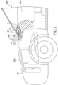
Figure 1 is a fragmentary, partly sectional schematic view illustrating an example of a ventilation system used in a vehicle according to an embodiment which is not part of the invention; -
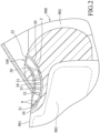
Figure 2 is an enlarged view of a part ofFigure 1 ; -
Figure 3 is a fragmentary perspective view of an interior space of the vehicle for illustrating an exemplary arrangement of a vent pipe of the ventilation system according to an embodiment which is not part of the invention; -
Figure 4 is a fragmentary perspective view of the interior space of the vehicle for illustrating another exemplary arrangement of the vent pipe of the ventilation system according to an embodiment which is not part of the invention; -
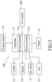
Figure 5 is a block diagram illustrating an example of the ventilation system according to an embodiment not being part of the invention; -
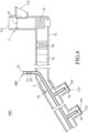
Figure 6 is a fragmentary sectional view illustrating an example of an air conditioning (A/C) apparatus according to an embodiment of invention; -
Figure 7 is a fragmentary perspective view of the interior space of the vehicle for illustrating an example of the A/C apparatus according to an embodiment according to the invention; -
Figure 8 is a block diagram illustrating an example of the A/C apparatus according to an embodiment according to the invention; and -
Figure 9 is a block diagram illustrating another example of the A/C apparatus according to an embodiment. - Before the embodiments are described in greater detail, it should be noted that where considered appropriate, reference numerals or terminal portions of reference numerals have been repeated among the figures to indicate corresponding or analogous elements, which may optionally have similar characteristics.
- Referring to
Figures 1 to 5 , an embodiment of aventilation system 100, which is not part of the invention, is illustrated. Theventilation system 100 is adapted to be used in avehicle 900. Thevehicle 900 may be implemented by one of a sedan, a sedan wagon, a van, a hatchback, a sport utility vehicle (SUV), a multipurpose vehicle, a sports car, a convertible, a bus and so on, but is not limited thereto. - The
vehicle 900 includes avehicle body 901 that defines an interior space 902 (i.e., a passenger compartment), and an air conditioning (A/C)system 903 disposed on thevehicle body 901. - The A/
C system 903 includes a plurality of air intakes 904 (only one is shown in the drawings), and a plurality ofair outlets 905. The A/C system 903 is configured to be controlled to operate in one of an internal circulation mode and an external circulation mode. When operating in the internal circulation mode, the A/C system 903 is configured to draw air from theinterior space 902 via theair intakes 904, to process the air thus drawn by filtering the air and adjusting temperature of the air, and to then expel the air thus processed via theair outlets 905 back to theinterior space 902. When operating in the external circulation mode, the A/C system 903 is configured to draw air from the outside of thevehicle 900, to process the air thus drawn by filtering the air and adjusting temperature of the air, and to expel the air thus processed via theair outlets 905 to theinterior space 902. - The
ventilation system 100 includes avent pipe 2, afan 31, afilter 32, acooler 33, aheater 34, anair valve 4, acontroller 51, anoxygen sensor 52 and atimer 53. Thecontroller 51 is adapted to be disposed partially in the interior space (902) of thevehicle body 901, and is electrically connected to thefan 31, thefilter 32, thecooler 33, theair valve 4, theoxygen sensor 52 and thetimer 53. - The
vent pipe 2 is adapted to be disposed on thevehicle body 901, and includes amain pipe 24 and a plurality ofside pipes 20. Thevent pipe 2 has anoutside communicating end 21 via which thevent pipe 2 is adapted to communicate with the outside of thevehicle body 901, and a plurality ofinside communicating ends 22 via which thevent pipe 2 is adapted to communicate with theinterior space 902. Themain pipe 24 defines the outside communicatingend 21. Theside pipes 20 are connected to themain pipe 24 and respectively define theinside communicating ends 22. Theinside communicating ends 22 may be positioned respectively beside theair outlets 905 near a driver seat and a front passenger seat as shown inFigure 3 , and accordingly air flowing from thevent pipe 2 into theinterior space 902 can rapidly mix with air flowing out of theair outlets 905 and spread throughout theinterior space 902. Alternatively, theinside communicating ends 22 may be positioned respectively beside the air intakes 904 (seeFigure 4 , where only one inside communicatingend 22 and oneair intake 904 are shown). In this way, air flowing from thevent pipe 2 into theinterior space 902 can be immediately drawn by the A/C system 903 via theair intakes 904 for further processing, and can then be expelled via theair outlets 905 back to theinterior space 902. - It should be noted that the positions of the
inside communicating ends 22 are not limited to the disclosure herein and may vary in other embodiments. Each of theinside communicating ends 22 may be positioned at any location that is exposed to theinterior space 902. - It should be noted that the number of the
inside communicating ends 22 is not limited to what is disclosed herein and may vary in other embodiments. In some embodiments, thevent pipe 2 has only one inside communicatingend 22. - The
fan 31, thefilter 32, thecooler 33 and theheater 34 are disposed in themain pipe 24 of thevent pipe 2, and are arranged in an extension direction of themain pipe 24. Thefan 31 is configured to be activated to produce airflow from theoutside communicating end 21 to each of theinside communicating ends 22, so air flowing from the outside of thevehicle body 901 into theinterior space 902 can be processed by thefilter 32, thecooler 33 and theheater 34 in thevent pipe 2. - In one embodiment, the
controller 51 is configured to control thefan 31 to rotate in one of a forward direction to produce airflow from theoutside communicating end 21 to each of theinside communicating ends 22, and a reverse direction to produce airflow from each of theinside communicating ends 22 to the outside communicatingend 21. When thefan 31 rotates in the forward direction, theventilation system 100 supplies air from the outside of thevehicle 900 to theinterior space 902. When thefan 31 rotates in the reverse direction, theventilation system 100 draws air from theinterior space 902 to the outside of thevehicle 900. - In one embodiment, the
ventilation system 100 further includes an air quality sensor (not shown). The air quality sensor is disposed in theinterior space 902, and is configured to measure the air quality within theinterior space 902. Thecontroller 51 is configured to determine, based on results of measurement made by the air quality sensor, whether the air quality within theinterior space 902 is poor (e.g., particles of toxic substance or cigarette smoke appear in the interior space 902). When it is determined that the air quality within theinterior space 902 is poor, thecontroller 51 is configured to control thefan 31 to rotate in the reverse direction to draw air from theinterior space 902 to the outside of thevehicle 900. - In one embodiment, the
controller 51 will be instantly activated when thevehicle 900 is unlocked by a remote control. Then, thecontroller 51 is configured to control thefan 31 to rotate in the reverse direction for a predetermined time period (e.g., five minutes) so as to refresh air in theinterior space 902. - The
filter 32 is configured to filter air passing through thefilter 32 in thevent pipe 2 so as to remove dust particles or hazardous substance from the air. - The cooler 33 is configured to be controlled by the
controller 51 to cool air passing through the cooler 33 in thevent pipe 2. - The
heater 34 is configured to be controlled by thecontroller 51 to heat air passing through theheater 34 in thevent pipe 2. - Since techniques of filtering, cooling and heating have been well known to one skilled in the relevant art, detailed explanation of the same is omitted herein for the sake of brevity.
- The
air valve 4 is disposed at the outside communicatingend 21 of thevent pipe 2. Thecontroller 51 is configured to control theair valve 4 to switch between an open state where theair valve 4 allows thevent pipe 2 to communicate with the outside of thevehicle body 901, and a closed state where theair valve 4 disallows thevent pipe 2 to communicate with the outside of thevehicle body 901. InFigure 2 , the closed state of theair valve 4 is indicated by sloid lines, and the open state of theair valve 4 is indicated by dashed lines. Theair valve 4 may be implemented by an electric valve, but is not limited thereto. Since implementation of theair valve 4 has been well known to one skilled in the relevant art, detailed explanation of the same is omitted herein for the sake of brevity. - It should be noted that in some embodiments, the
ventilation system 100 does not include theair valve 4. - The
oxygen sensor 52 is adapted to be disposed in theinterior space 902 of thevehicle body 901. Theoxygen sensor 52 is configured to measure oxygen concentration in theinterior space 902 to generate a concentration indication signal, and to output the concentration indication signal to thecontroller 51. - The
controller 51 is operable in one of a triggered ventilation mode and a regular ventilation mode. - The
controller 51 is adapted to be further electrically connected to the A/C system 903, and to be notified by the A/C system 903 that the A/C system 903 operates in which one of the internal circulation mode and the external circulation mode. Thecontroller 51 includes acontrol panel 511 that is disposed in theinterior space 902, and a processing unit (not shown) that is configured to implement the operations of thecontroller 51 described herein. Thecontrol panel 511 is configured to be operated by a user to activate the cooler 33 and theheater 34, independently, and to make thecontroller 51 operate in the triggered ventilation mode or the regular ventilation mode. - In the triggered ventilation mode, the
controller 51 is configured to activate theoxygen sensor 52 to measure oxygen concentration in theinterior space 902 when the A/C system 903 notifies thecontroller 51 that the A/C system 903 operates in the internal circulation mode. Thecontroller 51 is further configured to determine whether the oxygen concentration is lower than a low-oxygen-concentration threshold based on the concentration indication signal. When it is determined that a first ventilation condition is satisfied (i.e., that the oxygen concentration is lower than the low-oxygen-concentration threshold), thecontroller 51 is configured to control thetimer 53 to time a preset time period (e.g., five minutes), and during the preset time period, to control theair valve 4 to switch to the open state and to activate thefan 31 to rotate in the forward direction so as to produce airflow from the outside of thevehicle 900 to theinterior space 902. When the preset time period has elapsed, thecontroller 51 is configured to control theair valve 4 to switch to the closed state and to stop thefan 31. In this way, whenever the oxygen concentration falls to an abnormal level, the oxygen concentration in theinterior space 902 may be raised to a normal level by theventilation system 100 that supplies airflow from the outside of thevehicle 900 to theinterior space 902. - In the regular ventilation mode, the
controller 51 is configured, when the A/C system 903 notifies thecontroller 51 that the A/C system 903 operates in the internal circulation mode, to control thetimer 53 to repeatedly time a first preset duration (e.g., fifteen or thirty minutes) and time a second preset duration (e.g., five minutes) immediately following completion of timing of the first preset duration, to control theair valve 4 to switch to the open state and activate thefan 31 to produce airflow from the outside of thevehicle 900 to theinterior space 902 during the second preset duration, and to control theair valve 4 to switch to the closed state and stop thefan 31 during the first preset duration. That is to say, when a second ventilation condition is satisfied (i.e., every time when the first preset duration elapses), thecontroller 51 controls theair valve 4 to switch to the open state and activates the fan3 1 to produce airflow from the outside of thevehicle 900 to theinterior space 902. In this way, the oxygen concentration in theinterior space 902 may be maintained at a normal level by theventilation system 100 that periodically supplies airflow from the outside of thevehicle 900 to theinterior space 902. - In one embodiment, the
controller 51 further includes apower switch 512. Thepower switch 512 is exposed to theinterior space 902, and is electrically connected to an electrical system (not shown) of thevehicle 900. Thepower switch 512 is operable to enable or disable the controller 51 (i.e., to enable thecontroller 51, thepower switch 512 is turned on to provide electric power from the electrical system to the controller 51), such that thecontrol panel 511 is operable to make thecontroller 51 operate in the triggered ventilation mode or the regular ventilation mode and that thecontroller 51 is able to control thefan 31 and theair valve 4 according to results of measurement made by the oxygen sensor 52 (i.e., the triggered ventilation mode) or timing results made by the timer 53 (i.e., the regular ventilation mode). - Referring to
Figures 6 ,7 and8 , an embodiment of an A/C apparatus 600 according to the invention is illustrated. The A/C apparatus 600 is adapted to be used in thevehicle 900 that is previously described. - The A/
C apparatus 600 includes an A/C system 7 and a ventilation system 100'. - Since the ventilation system 100' is similar to the
ventilation system 100 that has been described previously, only differences from theventilation system 100 are explained in the following for the sake of brevity. - The
controller 51 of the ventilation system 100' is further electrically connected to the A/C system 7. - The A/C system 7 is installed in the
vehicle 900, and includes anair duct 71, aduct valve 72, ablower 73, afiltering device 74 and an A/C device 75. - The
air duct 71 has anexternal inlet end 711 via which theair duct 71 is adapted to communicate with the outside of thevehicle 900, aninternal inlet end 712 via which theair duct 71 is adapted to communicate with theinterior space 902 of thevehicle 900, and a plurality of outlet ends 713 via which theair duct 71 is adapted to communicate with theinterior space 902 of thevehicle 900. Theair duct 71 allows air to flow from the outside of thevehicle 900 via theexternal inlet end 711 into theair duct 71, allows air to flow from theinterior space 902 via theinternal inlet end 712 into theair duct 71, and allows air in theair duct 71 to flow into theinterior space 902 via the outlet ends 713. It should be noted that only some of the outlet ends 713 are illustrated inFigures 6 and7 . - The
duct valve 72 is disposed between theexternal inlet end 711 and theinternal inlet end 712. Theduct valve 72 is configured to be controlled by thecontroller 51 to switch between an internal circulation state (indicated by dashed lines) and an external circulation state (indicated by solid lines). When theduct valve 72 is in the internal circulation state, only air in theinterior space 902 is allowed to flow into theair duct 71 via theinternal inlet end 712 and back to theinterior space 902 via the outlet ends 713, and air outside of thevehicle 900 cannot flow into theinterior space 902. When theduct valve 72 is in the external circulation state, air outside of thevehicle 900 is allowed to flow into theair duct 71 via theexternal inlet end 711 and then into theinterior space 902 via the outlet ends 713. Since using theduct valve 72 to control air flow has been well known to one skilled in the relevant art, detailed explanation of the same is omitted herein for the sake of brevity. - The
blower 73, thefiltering device 74 and the A/C device 75 are disposed in theair duct 71. Theblower 73 is configured to be controlled by thecontroller 51 to drive air to flow from theexternal inlet end 711 or theinternal inlet end 712 through thefiltering device 74 and the A/C device 75 to the plurality of outlet ends 713. - The
filtering device 74 is configured to filter air passing through thefiltering device 74 so as to remove undesired substance (e.g., dust particles, pollen, or pathogens) from the air. - The A/
C device 75 is configured to be controlled by thecontroller 51 to regulate temperature (e.g., to warm up or to cool down) of air flowing through the A/C device 75. - Since implementations of the
blower 73, thefiltering device 74 and the A/C device 75 have been well known to one skilled in the relevant art, detailed explanation of the same is omitted herein for the sake of brevity. - A majority of the
vent pipe 2 extends along theair duct 71 in theair duct 71. Thevent pipe 2 has an outside communicatingend 21 that is exposed out of theair duct 71, a plurality of inside communicating ends 22 that respectively correspond to the outlet ends 713 of theair duct 71, and a connectingportion 23 that connects the outside communicatingend 21 and the inside communicating ends 22. The inside communicating ends 22 are disposed respectively at the outlet ends 713 of theair duct 71 and communicate respectively with the outlet ends 713. Thevent pipe 2 is adapted to communicate with the outside of thevehicle 900 via theoutside communicating end 21. Thevent pipe 2 is adapted to communicate with theinterior space 902 of thevehicle 900 via the inside communicating ends 22. - It is worth to note that the connecting
portion 23 extends through a posterior portion of theair duct 71 that is spaced apart from theexternal inlet end 711 and theinternal inlet end 712 and that is located behind theblower 73, thefiltering device 74 and the A/C device 75 with respect to a direction of airflow from theexternal inlet end 711 or theinternal inlet end 712 to the outlet ends 713. Air flowing through the A/C device 75 will flow through thevent pipe 2, and thus can be utilized to warm up or cool down thevent pipe 2 and air inside thevent pipe 2. It should be noted that the ventilation system 100' does not include the cooler 33 and theheater 34 as with theventilation system 100 previously described. - The
fan 31 is disposed nearby the outside communicatingend 21, and is configured to be activated by thecontroller 51 to produce airflow from the outside communicatingend 21 to each of the inside communicating ends 22. However, the location of thefan 31 is not limited to what is disclosed herein and may vary in other embodiments. - The
filter 32 is disposed in thevent pipe 2, and is configured to filter air passing through thefilter 32 so as to remove undesired substance (e.g., dust particles, pollen, or pathogens) from the air. - The ventilation system 100' further includes a plurality of
air valve units 35 that respectively correspond to the inside communicating ends 22 of the vent pipe 2 (and thus respectively correspond to the outlet ends 713) . Thecontroller 51 is further electrically connected to theair valve units 35. - The
controller 51 includes a main A/C controlling module 513 and an auxiliary A/C controlling module 514. The main A/C controlling module 513 is configured to control theduct valve 72, theblower 73 and the A/C device 75 of the A/C system 7. The auxiliary A/C controlling module 514 is configured to control thefan 31 and theair valve units 35 of the ventilation system 100'. - The main A/
C controlling module 513 is configured to be operated to control theduct valve 72 to switch between the internal circulation state and the external circulation state, and to control the A/C device 75 to regulate the temperature of the air flowing therethrough. - It should be noted that each of the main A/
C controlling module 513 and the auxiliary A/C controlling module 514 may be implemented by one of hardware, firmware, software, and any combination thereof. For example, the main A/C controlling module 513 and the auxiliary A/C controlling module 514 may be implemented to be software modules in a program, where the software modules contain codes and instructions to carry out specific functionalities of thecontroller 51, and can be called individually or together. - In one embodiment, each of the
air valve units 35 includes anair valve 351 and ahuman presence detector 352. - The
air valve 351 is disposed at a corresponding one of the inside communicating ends 22 of thevent pipe 2, and is configured to be controlled by the auxiliary A/C controlling module 514 of thecontroller 51 to switch between an open state where theair valve 351 allows thevent pipe 2 to communicate with theinterior space 902 via theair valve 351 and a closed state where theair valve 351 disallows thevent pipe 2 to communicate with theinterior space 902 via theair valve 351. - The
human presence detector 352 is disposed on thevehicle body 901 around one of the outlet ends 713 at which the corresponding one of the inside communicating ends 22 is disposed, and is exposed to theinterior space 902. Thehuman presence detector 352 is configured to detect presence of a human in a preset region in front of the corresponding one of the outlet ends 713 in theinterior space 902 to generate a presence indication signal, and to output the presence indication signal. - The
human presence detector 352 may be implemented by a reflective optical sensor. For example, thehuman presence detector 352 is configured to emit a light beam, and to receive a reflection of the light beam so as to generate the presence indication signal. Alternatively, thehuman presence detector 352 may be implemented using infrared detection technologies, in which case thehuman presence detector 352 is configured to sense infrared light radiated from a human who is on the driver seat or the front passenger seat. However, implementation of thehuman presence detector 352 is not limited to the disclosure herein and may vary in other embodiments. - In one embodiment, the
human presence detector 352 is disposed on a seat of thevehicle 900, and is configured to detect presence of a human based on a weight load of the seat. - It is worth to note that the
air valves 351 respectively of theair valve units 35 are disposed respectively at the inside communicating ends 22 of thevent pipe 2. The auxiliary A/C controlling module 514 of thecontroller 51 is configured to determine, based on the presence indication signals respectively from thehuman presence detectors 352 respectively of theair valve units 35, whether a human is present in any of the preset regions that are associated respectively with thehuman presence detectors 352 in theinterior space 902. When it is determined that one of the presence indication signals indicates presence of a human in one of the preset regions, the auxiliary A/C controlling module 514 is configured to control one of theair valves 351 that corresponds to one of thehuman presence detectors 352 that outputted said one of the presence indication signals to switch to the open state, and to activate thefan 31 to produce airflow from the outside communicatingend 21 to one of the inside communicating ends 22 that corresponds to said one of theair valves 351. In this way, air flowing from the inside communicating ends 22 of thevent pipe 2 would mix with air flowing from the outlet ends 713 of theair duct 71, and then flow into theinterior space 902. Therefore, oxygen concentration in theinterior space 902 may be raised. - In one embodiment (see
Figure 9 ), each of theair valve units 35 includes avalve switch 353, and theair valve 351 as previously described. - The
valve switch 353 is disposed on thevehicle body 901, and is exposed to theinterior space 902. Thevalve switch 353 is electrically connected to theair valve 351, and is operable to control theair valve 351 to switch between the open state and the closed state. Thevalve switch 353 is configured to output a trigger signal to the auxiliary A/C controlling module 514 of thecontroller 51 when thevalve switch 353 is operated by a driver or a passenger. - When the
valve switch 353 of one of theair valve units 35 is operated to control the correspondingair valve 351 to switch to the open state, in response to the trigger signal outputted thereby, the auxiliary A/C controlling module 514 of thecontroller 51 is configured to control the corresponding one of theair valves 351 to switch to the open state, and to activate thefan 31 to produce airflow from the outside communicatingend 21 to the corresponding one of the inside communicating ends 22 where thecorresponding air valve 351 is disposed. - Hence, air flowing from the corresponding one of the inside communicating ends 22 of the
vent pipe 2 would mix with air flowing from the corresponding one of the outlet ends 713 of theair duct 71, and then flow into theinterior space 902. - In one embodiment, the ventilation system 100' includes only one
air valve unit 35. Theair valve unit 35 includes anair valve 351 and ahuman presence detector 352. Theair valve 351 is disposed at one of the inside communicating ends 22 of thevent pipe 2, and is configured to be controlled to switch between an open state where theair valve 351 allows thevent pipe 2 to communicate with theinterior space 902 and a closed state where theair valve 351 disallows thevent pipe 2 to communicate with theinterior space 902. Thehuman presence detector 352 is adapted to be disposed on thevehicle body 901, and is configured to detect presence of a human in a preset region in theinterior space 902 to generate a presence indication signal and to output the presence indication signal. Thecontroller 51 is electrically connected to thefan 31 and theair valve unit 35, and is configured to determine, based on the presence indication signal, whether a human is present in the preset region in theinterior space 902, and when it is determined that the presence indication signal indicates presence of a human in the preset region, to activate thefan 31 to produce airflow from the outside communicatingend 21 to theinside communicating end 22 and to control theair valve 351 to switch to the open state. - In one embodiment, the ventilation system 100' includes only one
air valve unit 35. Theair valve unit 35 includes anair valve 351 and avalve switch 353. Theair valve 351 is disposed at one of the inside communicating ends 22 of thevent pipe 2, and is configured to be controlled to switch between an open state where theair valve 351 allows thevent pipe 2 to communicate with theinterior space 902 and a closed state where theair valve 351 disallows thevent pipe 2 to communicate with theinterior space 902. Thevalve switch 353 is disposed on thevehicle body 901, is electrically connected to theair valve 351, and is operable to control theair valve 351 to switch between the open state and the closed state. Thecontroller 51 is electrically connected to thefan 31 and theair valve unit 35, and is adapted to be disposed partially in theinterior space 902 of thevehicle body 901. Thecontroller 51 is configured to activate thefan 31 to produce airflow from the outside communicatingend 21 to theinside communicating end 22 when theair valve 351 switches to the open state. - In one embodiment, the
ventilation system 100 that is previously described with reference toFigures 1 to 5 further includes theair valve units 35 as described in connection withFigures 6 to 8 orFigure 9 . - To sum up, the ventilation system according to the disclosure forces air to flow from the outside of a vehicle to an interior space of the vehicle when it is determined that oxygen concentration in the interior space is lower than a threshold, and regularly forces air to flow from the outside of the vehicle to the interior space of the vehicle when an A/C system of the vehicle operates in the internal circulation mode. In this way, the oxygen concentration in the interior space can be ensured to be maintained at a normal level, so issues of fatigue driving or drowsy driving due to low oxygen concentration may be alleviated.
- According to the invention, the ventilation system is integrated with the A/C system as an A/C apparatus. The ventilation system is capable of adjusting temperature of the airflow by utilizing the A/C system without an additional cooler or an additional heater. Moreover, placing inside communicating end(s) of the ventilation system in proximity to outlet end(s) of the A/C system allows air flowing out of the ventilation system and air flowing out of the A/C system to rapidly mix together and then spread throughout the interior space, thereby minimizing temperature difference, to which a person may not adapt well, of air flowing from the ventilation system and the A/C system.
Claims (7)
- An air conditioning (A/C) apparatus (600), adapted to be used in a vehicle (900), the vehicle (900) including a vehicle body (901) that defines an interior space (902), said A/C apparatus (600) including:a ventilation system (100') that includes a vent pipe (2) that is, when said A/C apparatus (600) is mounted on the vehicle (900), disposed on the vehicle body (901), and that hasan outside communicating end (21) via which said vent pipe (2), when said A/C apparatus (600) is mounted on the vehicle (900), communicates with the outside of the vehicle body (901), andan inside communicating end (22) via which said vent pipe (2), when said A/C apparatus (600) is mounted on the vehicle (900), communicates with the interior space (902); andan A/C system (7) includingan air duct (71) that has an external inlet end (711) via which said air duct (71) communicates with the outside of the vehicle (900) when said A/C apparatus (600) is mounted on the vehicle (900), and a plurality of outlet ends (713) via which said air duct (71) communicates with the interior space (902) of the vehicle (900) when said A/C apparatus (600) is mounted on the vehicle (900),an A/C device (75) that is disposed in said air duct (71), and that is controllable to regulate temperature of air flowing through said A/C device (75), anda blower (73) that is disposed in said air duct (71), and that is controllable to drive air to flow from said external inlet end (711) through said A/C device (75) to said plurality of outlet ends (713),said A/C apparatus (600) being characterized in that:said ventilation system (100') further includes a fan (31) that is disposed in said vent pipe (2), and that is configurable to beactivated to produce airflow from said outside communicating end (21) to said inside communicating end (22) when said A/C apparatus (600) is mounted on the vehicle (900);a majority of said vent pipe (2) extends along said air duct (71) in said air duct (71);said outside communicating end (21) is exposed out of said air duct (71); andsaid inside communicating end (22) is disposed at one of said plurality of outlet ends (713) of said air duct (71) and communicates with said one of said plurality of outlet ends (713).
- The A/C apparatus (600) as claimed in claim 1, wherein:said ventilation system (100') further includes an air valve (4) that is disposed at said vent pipe (2), and a controller (51) that is electrically connected to said air valve (4) and said fan (31); andsaid controller (51) is configured tocontrol said air valve (4) to switch between an open state where said air valve (4) allows said vent pipe (2) to communicate with the outside of the vehicle body (901), and a closed state where said air valve (4) disallows said vent pipe (2) to communicate with the outside of the vehicle body (901), andactivate said fan (31) to produce airflow from said outside communicating end (21) to said inside communicating end (22) when controlling said air valve (4) to switch to the open state.
- The A/C apparatus (600) as claimed in claim 2, wherein said controller (51) includes:a main A/C controlling module (513) that is configured to control said A/C device (75) and said blower (73); andan auxiliary A/C controlling module (514) that is configured to control said air valve (4) and said fan (31).
- The A/C apparatus (600) as claimed in claim 1, further comprising a controller (51), wherein:said vent pipe (2) includes a plurality of said inside communicating ends (22) that respectively correspond to said outlet ends (713) of said air duct (71);said ventilation system (100') further includes at least one air valve unit (35) that includesan air valve (351) which is disposed at one of said inside communicating ends (22) of said vent pipe (2), and which is configured to be controlled to switch between an open state where said air valve (351) allows said vent pipe (2) to communicate with the interior space (902) and a closed state where said air valve (351) disallows said vent pipe (2) to communicate with the interior space (902), anda valve switch (353) which is disposed on the vehicle body (901) when said A/C apparatus (600) is mounted on the vehicle (900), which is electrically connected to said air valve (351), and which is operable to control said air valve (351) to switch between the open state and the closed state; andsaid controller (51) is electrically connected to said fan (31) and said at least one air valve unit (35), and is configured to activate said fan (31) to produce airflow from said outside communicating end (21) to said one of said inside communicating ends (22) when said air valve (351) switches to the open state.
- The A/C apparatus (600) as claimed in claim 4, wherein:said at least one air valve unit (35) includes a plurality of air valve units (35) that respectively correspond to said inside communicating ends (22) of said vent pipe (2);said air valves (351) respectively of said air valve units (35) are disposed respectively at said inside communicating ends (22) of said vent pipe (2); andwhen said valve switch (353) of one of said air valve units (35) is operated to control the corresponding one of said air valves (351) to switch to the open state, said controller (51) is configured to activate said fan (31) to produce airflow from said outside communicating end (21) to the corresponding one of said inside communicating ends (22) where the corresponding one of said air valves (351) is disposed.
- The A/C apparatus (600) as claimed in claim 1, further comprising a controller (51), wherein:said vent pipe (2) includes a plurality of said inside communicating ends (22) that respectively correspond to said outlet ends (713) of said air duct (71);said ventilation system (100') further includes at least one air valve unit (35) that includesan air valve (351) which is disposed at one of said inside communicating ends (22) of said vent pipe (2), and which is configured to be controlled to switch between an open state where said air valve (351) allows said vent pipe (2) to communicate with the interior space (902) and a closed state where said air valve (351) disallows said vent pipe (2) to communicate with the interior space (902), anda human presence detector (352) which is disposed on the vehicle body (901) when said A/C apparatus (600) is mounted on the vehicle (900), which is configured to detect presence of a human in a preset region in the interior space (902) to generate a presence indication signal and to output the presence indication signal; andsaid controller (51) is electrically connected to said fan (31) and said at least one air valve unit (35), and is configured to determine, based on the presence indication signal, whether a human is present in the preset region in the interior space (902), and when it is determined that the presence indication signal indicates presence of a human in the preset region, to activate said fan (31) to produce airflow from said outside communicating end (21) to said one of said inside communicating ends (22) and to control said air valve (351) to switch to the open state.
- The A/C apparatus (600) as claimed in claim 6, wherein:said at least one air valve unit (35) includes a plurality of air valve units (35) that respectively correspond to said inside communicating ends (22) of said vent pipe (2), and said air valves (351) respectively of said air valve units (35) are disposed respectively at said inside communicating ends (22) of said vent pipe (2); andsaid controller (51) is configured to determine, based on the presence indication signals respectively from said human presence detectors (352) respectively of said air valve units (35), whether a human is preset in any of the preset regions that are associated respectively with said human presence detectors (352) in the interior space (902), and when it is determined that one of the presence indication signals indicates presence of a human in one of the preset regions, to activate said fan (31) to produce airflow from said outside communicating end (21) to one of said inside communicating ends (22) and to control one of said air valves (351) that corresponds to one of said human presence detectors (352) that outputted said one of the presence indication signals to switch to the open state.
Applications Claiming Priority (1)
| Application Number | Priority Date | Filing Date | Title |
|---|---|---|---|
| TW110110058A TWI788807B (en) | 2021-02-26 | 2021-03-19 | Vehicle Air Conditioning Equipment |
Publications (4)
| Publication Number | Publication Date |
|---|---|
| EP4059746A1 EP4059746A1 (en) | 2022-09-21 |
| EP4059746B1 true EP4059746B1 (en) | 2024-10-30 |
| EP4059746C0 EP4059746C0 (en) | 2024-10-30 |
| EP4059746B8 EP4059746B8 (en) | 2024-12-25 |
Family
ID=80787038
Family Applications (1)
| Application Number | Title | Priority Date | Filing Date |
|---|---|---|---|
| EP22162675.7A Active EP4059746B8 (en) | 2021-03-19 | 2022-03-17 | Air conditioning apparatus and ventilation system |
Country Status (5)
| Country | Link |
|---|---|
| US (1) | US12103361B2 (en) |
| EP (1) | EP4059746B8 (en) |
| JP (1) | JP2022145667A (en) |
| KR (1) | KR20220131199A (en) |
| CA (1) | CA3152673A1 (en) |
Families Citing this family (1)
| Publication number | Priority date | Publication date | Assignee | Title |
|---|---|---|---|---|
| CN116749718A (en) * | 2023-07-06 | 2023-09-15 | 岚图汽车科技有限公司 | External circulation switching control method, control processor, system and medium of air conditioning system |
Family Cites Families (24)
| Publication number | Priority date | Publication date | Assignee | Title |
|---|---|---|---|---|
| US2627218A (en) * | 1950-06-10 | 1953-02-03 | Stanley S Katz | Air conditioning unit for automotive vehicles |
| DE3808319A1 (en) * | 1988-03-12 | 1989-09-21 | Audi Ag | CONTROL FOR A AIR CONDITIONING OF MOTOR VEHICLES |
| DE4217393C2 (en) * | 1992-05-26 | 2000-09-28 | Bosch Gmbh Robert | Method for controlling a ventilation device of a motor vehicle interior |
| DE19704254A1 (en) * | 1997-02-05 | 1998-08-06 | Hella Kg Hueck & Co | Air conditioning system for the interior of a vehicle |
| KR20010065954A (en) * | 1999-12-30 | 2001-07-11 | 이계안 | Air conditioning device for automobile |
| DE10259973B4 (en) * | 2002-12-19 | 2008-03-20 | Daimler Ag | Method of operating an air conditioner |
| US7357176B2 (en) * | 2004-10-21 | 2008-04-15 | Honda Motor Co., Ltd. | Method and apparatus for controlling mixture of fresh and recirculated air in a vehicle |
| DE102006003071A1 (en) * | 2006-01-20 | 2007-08-02 | Siemens Ag | Composition regulating method e.g. for motor vehicle interior space, involves regulating air composition based on fresh air supply initially being measured by means of operating parameters of air supply of motor vehicle |
| EP2202106B1 (en) * | 2008-12-24 | 2013-07-03 | Iveco France S.A. | Air treatment unit for a transport vehicle and corresponding control method |
| US20130037252A1 (en) * | 2011-08-12 | 2013-02-14 | GM Global Technology Operations LLC | Smart hvac system having occupant detection capability |
| TWM528259U (en) * | 2016-01-15 | 2016-09-11 | 張漢卿 | Air conditioning system |
| CN105674412A (en) * | 2016-04-06 | 2016-06-15 | 王功军 | Household air conditioner capable of automatically adjusting fresh air volume |
| US20180134120A1 (en) * | 2016-11-16 | 2018-05-17 | Calin Marginean | Vehicle hvac system |
| CN106377975A (en) | 2016-11-17 | 2017-02-08 | 南京大学环境规划设计研究院有限公司 | Automotive air purifier and purification method thereof |
| DE102016014028B4 (en) | 2016-11-24 | 2021-09-09 | Daimler Ag | Method and vehicle air conditioning system for ventilating a vehicle interior |
| KR102453824B1 (en) * | 2017-11-06 | 2022-10-12 | 현대자동차주식회사 | Air conditioning system for vehicle |
| CN208035899U (en) | 2018-04-13 | 2018-11-02 | 山东华宇工学院 | A kind of vehicle-mounted type intelligence fresh air system |
| WO2020179186A1 (en) * | 2019-03-01 | 2020-09-10 | パナソニックIpマネジメント株式会社 | Sleepiness prediction device, moving body, and sleepiness prediction method |
| DE102019125015B4 (en) * | 2019-09-17 | 2023-11-02 | Illinois Tool Works Inc. | AUTOMATIC AIR VENTILATION SYSTEM WITH DIFFERENT VENTILATION SITUATIONS |
| KR20210071620A (en) * | 2019-12-06 | 2021-06-16 | 현대자동차주식회사 | Vehicle hvac system |
| NL2025974B1 (en) * | 2020-07-02 | 2022-03-08 | Atlas Technologies Holding Bv | Vehicle comprising a thermal conditioning system |
| TW202202357A (en) * | 2020-07-09 | 2022-01-16 | 魏榮宗 | Vehicle Air Conditioning System |
| CN111907291B (en) * | 2020-07-24 | 2022-03-18 | 东风商用车有限公司 | Cab air conditioning method and system, terminal device and storage medium |
| US12017506B2 (en) * | 2020-08-20 | 2024-06-25 | Denso International America, Inc. | Passenger cabin air control systems and methods |
-
2022
- 2022-03-16 CA CA3152673A patent/CA3152673A1/en active Pending
- 2022-03-17 EP EP22162675.7A patent/EP4059746B8/en active Active
- 2022-03-18 KR KR1020220034149A patent/KR20220131199A/en active Pending
- 2022-03-18 US US17/698,220 patent/US12103361B2/en active Active
- 2022-03-18 JP JP2022044525A patent/JP2022145667A/en active Pending
Also Published As
| Publication number | Publication date |
|---|---|
| CA3152673A1 (en) | 2022-09-19 |
| EP4059746B8 (en) | 2024-12-25 |
| US20220297508A1 (en) | 2022-09-22 |
| EP4059746A1 (en) | 2022-09-21 |
| EP4059746C0 (en) | 2024-10-30 |
| US12103361B2 (en) | 2024-10-01 |
| JP2022145667A (en) | 2022-10-04 |
| KR20220131199A (en) | 2022-09-27 |
Similar Documents
| Publication | Publication Date | Title |
|---|---|---|
| US9150132B2 (en) | Vehicle comfort system with efficient coordination of complementary thermal units | |
| US9862247B2 (en) | Directional climate control system with infrared targeting | |
| CN104918808B (en) | Air conditioning system for vehicles | |
| US8633424B2 (en) | Disengaging pressurizer blower in max heat setting to improve cabin heating | |
| JPH1067218A (en) | Air conditioner for traveling vehicles with air guide device adjustable in relation to solar radiation | |
| US20140338882A1 (en) | HVAC Control for Vehicles with Start/Stop Engines | |
| JP6269413B2 (en) | Humidifier for vehicle | |
| EP2388158B1 (en) | Air conditioning device for vehicle | |
| EP4059746B1 (en) | Air conditioning apparatus and ventilation system and | |
| EP3623184B1 (en) | Climate system in a passenger vehicle | |
| KR101946520B1 (en) | Air conditioning system for automotive vehicles | |
| CN107554234B (en) | Air conditioning control system and method for vehicle | |
| KR101606868B1 (en) | Air conditioning system for automotive vehicles | |
| JP5369476B2 (en) | Air conditioner for vehicles | |
| KR101636415B1 (en) | Air conditioning system for automotive vehicles | |
| EP1116612B1 (en) | Airconditioning and control system for controlling the climate in a vehicle compartment | |
| KR20170100348A (en) | Device and Method of Controlling Active Incar Sensor | |
| KR100211376B1 (en) | Automotive air conditioning and control method | |
| JPH08142648A (en) | Ventilation unit for vehicle | |
| JP2005349935A (en) | Air conditioner for vehicles | |
| KR102285986B1 (en) | Air conditioning system for automotive vehicles | |
| JP2020179792A (en) | Air conditioner for vehicle | |
| KR20010017008A (en) | Method and system for controlling air condition of vehicle | |
| KR0185148B1 (en) | How to automatically control the vehicle's defrost mode | |
| KR20110126266A (en) | Car air conditioner |
Legal Events
| Date | Code | Title | Description |
|---|---|---|---|
| PUAI | Public reference made under article 153(3) epc to a published international application that has entered the european phase |
Free format text: ORIGINAL CODE: 0009012 |
|
| STAA | Information on the status of an ep patent application or granted ep patent |
Free format text: STATUS: THE APPLICATION HAS BEEN PUBLISHED |
|
| AK | Designated contracting states |
Kind code of ref document: A1 Designated state(s): AL AT BE BG CH CY CZ DE DK EE ES FI FR GB GR HR HU IE IS IT LI LT LU LV MC MK MT NL NO PL PT RO RS SE SI SK SM TR |
|
| STAA | Information on the status of an ep patent application or granted ep patent |
Free format text: STATUS: REQUEST FOR EXAMINATION WAS MADE |
|
| 17P | Request for examination filed |
Effective date: 20230309 |
|
| RBV | Designated contracting states (corrected) |
Designated state(s): AL AT BE BG CH CY CZ DE DK EE ES FI FR GB GR HR HU IE IS IT LI LT LU LV MC MK MT NL NO PL PT RO RS SE SI SK SM TR |
|
| STAA | Information on the status of an ep patent application or granted ep patent |
Free format text: STATUS: EXAMINATION IS IN PROGRESS |
|
| 17Q | First examination report despatched |
Effective date: 20230809 |
|
| GRAP | Despatch of communication of intention to grant a patent |
Free format text: ORIGINAL CODE: EPIDOSNIGR1 |
|
| STAA | Information on the status of an ep patent application or granted ep patent |
Free format text: STATUS: GRANT OF PATENT IS INTENDED |
|
| INTG | Intention to grant announced |
Effective date: 20240524 |
|
| GRAS | Grant fee paid |
Free format text: ORIGINAL CODE: EPIDOSNIGR3 |
|
| GRAA | (expected) grant |
Free format text: ORIGINAL CODE: 0009210 |
|
| STAA | Information on the status of an ep patent application or granted ep patent |
Free format text: STATUS: THE PATENT HAS BEEN GRANTED |
|
| AK | Designated contracting states |
Kind code of ref document: B1 Designated state(s): AL AT BE BG CH CY CZ DE DK EE ES FI FR GB GR HR HU IE IS IT LI LT LU LV MC MK MT NL NO PL PT RO RS SE SI SK SM TR |
|
| REG | Reference to a national code |
Ref country code: GB Ref legal event code: FG4D |
|
| REG | Reference to a national code |
Ref country code: CH Ref legal event code: EP |
|
| REG | Reference to a national code |
Ref country code: IE Ref legal event code: FG4D |
|
| REG | Reference to a national code |
Ref country code: DE Ref legal event code: R096 Ref document number: 602022007141 Country of ref document: DE |
|
| REG | Reference to a national code |
Ref country code: CH Ref legal event code: PK Free format text: BERICHTIGUNG B8 |
|
| U01 | Request for unitary effect filed |
Effective date: 20241129 |
|
| U07 | Unitary effect registered |
Designated state(s): AT BE BG DE DK EE FI FR IT LT LU LV MT NL PT RO SE SI Effective date: 20241210 |
|
| PG25 | Lapsed in a contracting state [announced via postgrant information from national office to epo] |
Ref country code: HR Free format text: LAPSE BECAUSE OF FAILURE TO SUBMIT A TRANSLATION OF THE DESCRIPTION OR TO PAY THE FEE WITHIN THE PRESCRIBED TIME-LIMIT Effective date: 20241030 Ref country code: IS Free format text: LAPSE BECAUSE OF FAILURE TO SUBMIT A TRANSLATION OF THE DESCRIPTION OR TO PAY THE FEE WITHIN THE PRESCRIBED TIME-LIMIT Effective date: 20250228 |
|
| PG25 | Lapsed in a contracting state [announced via postgrant information from national office to epo] |
Ref country code: ES Free format text: LAPSE BECAUSE OF FAILURE TO SUBMIT A TRANSLATION OF THE DESCRIPTION OR TO PAY THE FEE WITHIN THE PRESCRIBED TIME-LIMIT Effective date: 20241030 |
|
| PG25 | Lapsed in a contracting state [announced via postgrant information from national office to epo] |
Ref country code: NO Free format text: LAPSE BECAUSE OF FAILURE TO SUBMIT A TRANSLATION OF THE DESCRIPTION OR TO PAY THE FEE WITHIN THE PRESCRIBED TIME-LIMIT Effective date: 20250130 |
|
| U20 | Renewal fee for the european patent with unitary effect paid |
Year of fee payment: 4 Effective date: 20250318 |
|
| PG25 | Lapsed in a contracting state [announced via postgrant information from national office to epo] |
Ref country code: GR Free format text: LAPSE BECAUSE OF FAILURE TO SUBMIT A TRANSLATION OF THE DESCRIPTION OR TO PAY THE FEE WITHIN THE PRESCRIBED TIME-LIMIT Effective date: 20250131 |
|
| PG25 | Lapsed in a contracting state [announced via postgrant information from national office to epo] |
Ref country code: PL Free format text: LAPSE BECAUSE OF FAILURE TO SUBMIT A TRANSLATION OF THE DESCRIPTION OR TO PAY THE FEE WITHIN THE PRESCRIBED TIME-LIMIT Effective date: 20241030 |
|
| PG25 | Lapsed in a contracting state [announced via postgrant information from national office to epo] |
Ref country code: RS Free format text: LAPSE BECAUSE OF FAILURE TO SUBMIT A TRANSLATION OF THE DESCRIPTION OR TO PAY THE FEE WITHIN THE PRESCRIBED TIME-LIMIT Effective date: 20250130 |
|
| PG25 | Lapsed in a contracting state [announced via postgrant information from national office to epo] |
Ref country code: SM Free format text: LAPSE BECAUSE OF FAILURE TO SUBMIT A TRANSLATION OF THE DESCRIPTION OR TO PAY THE FEE WITHIN THE PRESCRIBED TIME-LIMIT Effective date: 20241030 |
|
| PG25 | Lapsed in a contracting state [announced via postgrant information from national office to epo] |
Ref country code: SK Free format text: LAPSE BECAUSE OF FAILURE TO SUBMIT A TRANSLATION OF THE DESCRIPTION OR TO PAY THE FEE WITHIN THE PRESCRIBED TIME-LIMIT Effective date: 20241030 |
|
| PG25 | Lapsed in a contracting state [announced via postgrant information from national office to epo] |
Ref country code: CZ Free format text: LAPSE BECAUSE OF FAILURE TO SUBMIT A TRANSLATION OF THE DESCRIPTION OR TO PAY THE FEE WITHIN THE PRESCRIBED TIME-LIMIT Effective date: 20241030 |
|
| PLBE | No opposition filed within time limit |
Free format text: ORIGINAL CODE: 0009261 |
|
| STAA | Information on the status of an ep patent application or granted ep patent |
Free format text: STATUS: NO OPPOSITION FILED WITHIN TIME LIMIT |
|
| 26N | No opposition filed |
Effective date: 20250731 |
|
| PG25 | Lapsed in a contracting state [announced via postgrant information from national office to epo] |
Ref country code: MC Free format text: LAPSE BECAUSE OF FAILURE TO SUBMIT A TRANSLATION OF THE DESCRIPTION OR TO PAY THE FEE WITHIN THE PRESCRIBED TIME-LIMIT Effective date: 20241030 |
|
| REG | Reference to a national code |
Ref country code: CH Ref legal event code: H13 Free format text: ST27 STATUS EVENT CODE: U-0-0-H10-H13 (AS PROVIDED BY THE NATIONAL OFFICE) Effective date: 20251023 |
|
| PG25 | Lapsed in a contracting state [announced via postgrant information from national office to epo] |
Ref country code: CH Free format text: LAPSE BECAUSE OF NON-PAYMENT OF DUE FEES Effective date: 20250331 |
|
| PG25 | Lapsed in a contracting state [announced via postgrant information from national office to epo] |
Ref country code: IE Free format text: LAPSE BECAUSE OF NON-PAYMENT OF DUE FEES Effective date: 20250317 |
|
| U20 | Renewal fee for the european patent with unitary effect paid |
Year of fee payment: 5 Effective date: 20260302 |
|
| PGFP | Annual fee paid to national office [announced via postgrant information from national office to epo] |
Ref country code: GB Payment date: 20260302 Year of fee payment: 5 |