EP4059730A1 - Head bar unit and printing apparatus including head bar unit - Google Patents
Head bar unit and printing apparatus including head bar unit Download PDFInfo
- Publication number
- EP4059730A1 EP4059730A1 EP22161767.3A EP22161767A EP4059730A1 EP 4059730 A1 EP4059730 A1 EP 4059730A1 EP 22161767 A EP22161767 A EP 22161767A EP 4059730 A1 EP4059730 A1 EP 4059730A1
- Authority
- EP
- European Patent Office
- Prior art keywords
- stopper
- contact portion
- vertical direction
- head bar
- contact
- Prior art date
- Legal status (The legal status is an assumption and is not a legal conclusion. Google has not performed a legal analysis and makes no representation as to the accuracy of the status listed.)
- Granted
Links
Images



Classifications
-
- B—PERFORMING OPERATIONS; TRANSPORTING
- B41—PRINTING; LINING MACHINES; TYPEWRITERS; STAMPS
- B41J—TYPEWRITERS; SELECTIVE PRINTING MECHANISMS, i.e. MECHANISMS PRINTING OTHERWISE THAN FROM A FORME; CORRECTION OF TYPOGRAPHICAL ERRORS
- B41J25/00—Actions or mechanisms not otherwise provided for
- B41J25/304—Bodily-movable mechanisms for print heads or carriages movable towards or from paper surface
-
- B—PERFORMING OPERATIONS; TRANSPORTING
- B41—PRINTING; LINING MACHINES; TYPEWRITERS; STAMPS
- B41J—TYPEWRITERS; SELECTIVE PRINTING MECHANISMS, i.e. MECHANISMS PRINTING OTHERWISE THAN FROM A FORME; CORRECTION OF TYPOGRAPHICAL ERRORS
- B41J2/00—Typewriters or selective printing mechanisms characterised by the printing or marking process for which they are designed
- B41J2/005—Typewriters or selective printing mechanisms characterised by the printing or marking process for which they are designed characterised by bringing liquid or particles selectively into contact with a printing material
- B41J2/01—Ink jet
- B41J2/135—Nozzles
- B41J2/145—Arrangement thereof
-
- B—PERFORMING OPERATIONS; TRANSPORTING
- B41—PRINTING; LINING MACHINES; TYPEWRITERS; STAMPS
- B41J—TYPEWRITERS; SELECTIVE PRINTING MECHANISMS, i.e. MECHANISMS PRINTING OTHERWISE THAN FROM A FORME; CORRECTION OF TYPOGRAPHICAL ERRORS
- B41J2/00—Typewriters or selective printing mechanisms characterised by the printing or marking process for which they are designed
- B41J2/005—Typewriters or selective printing mechanisms characterised by the printing or marking process for which they are designed characterised by bringing liquid or particles selectively into contact with a printing material
- B41J2/01—Ink jet
- B41J2/135—Nozzles
- B41J2/165—Prevention or detection of nozzle clogging, e.g. cleaning, capping or moistening for nozzles
- B41J2/16585—Prevention or detection of nozzle clogging, e.g. cleaning, capping or moistening for nozzles for paper-width or non-reciprocating print heads
-
- B—PERFORMING OPERATIONS; TRANSPORTING
- B41—PRINTING; LINING MACHINES; TYPEWRITERS; STAMPS
- B41J—TYPEWRITERS; SELECTIVE PRINTING MECHANISMS, i.e. MECHANISMS PRINTING OTHERWISE THAN FROM A FORME; CORRECTION OF TYPOGRAPHICAL ERRORS
- B41J29/00—Details of, or accessories for, typewriters or selective printing mechanisms not otherwise provided for
- B41J29/38—Drives, motors, controls or automatic cut-off devices for the entire printing mechanism
-
- B—PERFORMING OPERATIONS; TRANSPORTING
- B41—PRINTING; LINING MACHINES; TYPEWRITERS; STAMPS
- B41J—TYPEWRITERS; SELECTIVE PRINTING MECHANISMS, i.e. MECHANISMS PRINTING OTHERWISE THAN FROM A FORME; CORRECTION OF TYPOGRAPHICAL ERRORS
- B41J2202/00—Embodiments of or processes related to ink-jet or thermal heads
- B41J2202/01—Embodiments of or processes related to ink-jet heads
- B41J2202/15—Moving nozzle or nozzle plate
-
- B—PERFORMING OPERATIONS; TRANSPORTING
- B41—PRINTING; LINING MACHINES; TYPEWRITERS; STAMPS
- B41J—TYPEWRITERS; SELECTIVE PRINTING MECHANISMS, i.e. MECHANISMS PRINTING OTHERWISE THAN FROM A FORME; CORRECTION OF TYPOGRAPHICAL ERRORS
- B41J2202/00—Embodiments of or processes related to ink-jet or thermal heads
- B41J2202/01—Embodiments of or processes related to ink-jet heads
- B41J2202/19—Assembling head units
-
- B—PERFORMING OPERATIONS; TRANSPORTING
- B41—PRINTING; LINING MACHINES; TYPEWRITERS; STAMPS
- B41J—TYPEWRITERS; SELECTIVE PRINTING MECHANISMS, i.e. MECHANISMS PRINTING OTHERWISE THAN FROM A FORME; CORRECTION OF TYPOGRAPHICAL ERRORS
- B41J2202/00—Embodiments of or processes related to ink-jet or thermal heads
- B41J2202/01—Embodiments of or processes related to ink-jet heads
- B41J2202/21—Line printing
Definitions
- the present disclosure relates to a head bar unit which includes a mechanism which moves a head bar having a plurality of heads in a vertical direction, and a printing apparatus which includes the head bar unit.
- a certain heretofore known printing apparatus includes a mechanism which moves vertically a head bar having a plurality of ink-jet heads by an air cylinder (for example, refer to Japanese Patent Application Laid-open Publication No. 2013-240988 ).
- the heretofore known printing apparatus further includes a first engaging member which is extended downward below the head bar, as a mechanism which carries out a fine adjustment of a vertical position of the head bar after the head bar has moved downward, and a second engaging member which is extended upward below the head bar, and which is engaged with the first engaging member.
- the position in the vertical direction of the head bar is determined by the first engaging member and the second engaging member being engaged.
- the first engaging member is provided at a front end of a male screw member screwed to a female screw member, and it is possible to move the first engaging member in the vertical direction by a motor rotating the male screw member. In such manner, by moving the first engaging member in the vertical direction by the motor, it is possible to adjust the vertical position of the head bar.
- the first engaging member is moved in the vertical direction by rotating the male screw member by the motor.
- the head bar With the movement of the first engaging member, the head bar also moves in the vertical direction. Therefore, in a case in which a weight of the head bar is large (heavy), it was necessary to select a motor with a high output as the motor for rotating the male screw member. Since a cost of a drive system including such motor with a high output and a gear head to be connected to the motor with a high output becomes extremely high, it was becoming a factor contributing to a high cost of the printing apparatus.
- An object of the present disclosure is to provide a technology which enables to adjust the vertical position of the head bar, without using a motor with a high output.
- a head bar unit including a head bar, an adjuster and a movement.
- the head bar includes a plurality of heads.
- the adjuster is configured to adjust positions in a vertical direction of the plurality of heads.
- the movement is configured to move the head bar and the adjuster in the vertical direction.
- the adjuster includes a motor, a rotator and a stopper.
- the rotator includes a plurality of contact portions. Positions of the contact portions in the vertical direction are different from each other.
- the rotator is configured to be rotated by the motor around a rotating shaft which is parallel to the vertical direction.
- the stopper is located at a position facing the rotator in the vertical direction, and is configured to position the rotator in the vertical direction, by making contact with one of the contact portions.
- the motor in the adjuster being used for rotating the rotator is not required to be a motor with a high output which is necessary for moving the head bar up and down for example.
- the motor in the adjuster being used for rotating the rotator since it is possible to use an air cylinder for instance, as the movement which moves the head bar up and down, it is possible to reduce a cost as compared to that in a case of moving the head bar up and down by using a motor.
- the plurality of contact portions on the rotator to be rotated by the motor are at mutually different positions in the vertical direction. By selecting any of the contact portions to make a contact with the stopper, it is possible to adjust easily the position of the head bar in the vertical direction.
- Fig. 1 is a plan view depicting schematically the printing apparatus 1.
- a conveyance direction of a recording medium M corresponds to a frontward-rearward direction of the printing apparatus 1.
- a direction of width of the recording medium M corresponds to a left-right direction of the printing apparatus 1.
- a direction orthogonal to the frontward-rearward direction and the left-right direction, or in other words, a direction perpendicular to a paper surface in Fig. 1 corresponds to a vertical direction of the printing apparatus 1.
- the printing apparatus 1 includes a platen 3, four heads 10, two conveyance rollers 5A and 5B, and a controller 7 accommodated inside a casing 2. Moreover, although it is not depicted in Fig. 1 , the printing apparatus 1 includes a maintenance unit 20 (refer to Fig. 3 ), a movement 50 (refer to Fig. 5 ), and an adjuster 60 (refer to Fig. 5 ) that will be described later.
- the printing apparatus 1 includes a maintenance unit 20 (refer to Fig. 3 ), a movement 50 (refer to Fig. 5 ), and an adjuster 60 (refer to Fig. 5 ) that will be described later.
- at least one head bar 10, the movement 50, and the adjuster 60 are collectively called as a head bar unit.
- the head bar unit and the maintenance unit 20 are collectively called as a head bar system.
- the recording medium M is to be placed on an upper surface of the platen 3.
- the four head bars 10 are arranged above the platen 3, to be facing the platen 3.
- An ink of a different color is supplied to each head bar 10 from an ink tank 3 (refer to Fig. 3 ).
- a structure of the head bar 10 will be described later in detail.
- the two conveyance rollers 5A and 5A are arranged at a front side and a rear side respectively.
- Each of the two conveyance rollers 5A and 5B is driven by a motor which is not depicted in the diagram, and the recording medium M on the platen 3 is transported to a downstream side (front side) of the conveyance direction.
- the controller 7 includes an FPGA (Field Programmable Gate Array), an EEPROM (Electrically Erasable Programmable Read-only Memory), and a RAM (Random Access Memory).
- the controller 7 may also include a CPU (Central Processing Unit) or an ASIC (Application Specific Integrated Circuit).
- the controller 7 is data-communicably connected to an external apparatus 9 such as a PC (Personal Computer), and controls each section of the printing apparatus 1 on the basis of print data that has been sent from the external apparatus 9.
- an external apparatus 9 such as a PC (Personal Computer
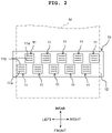
- Fig. 2 is a plan view depicting one of the four head bars 10 in a simplified manner.
- Fig. 3 is a simplified cross-sectional view of the printing apparatus 1.
- the head bar 10 includes a plurality of heads 11 (10 heads 11 in the present embodiment), and a holder bar 12 which holds the plurality of heads 11.
- the holder bar 12 has a shape of a rectangular plate which is long in the left-right direction.
- the plurality of heads 11 form two head rows arranged side-by-side in the frontward-rearward direction. Five heads 11 arranged side-by-side in the left-right direction are included in each head row. Positions of the heads 11 in the two head rows are misaligned in the left-right direction. In other words, the 10 heads 11 are arranged in a zigzag form.
- a lower surface 11b of each head 11 is a nozzle surface in which a plurality of nozzles 11a is formed. As depicted in Fig. 2 , the plurality of nozzles 11a of the head 11 are arranged side-by-side in a row along the left-right direction which is a longitudinal direction of the head bar 10 (holder bar 12).
- a reservoir 14 is arranged at an upper side (above) the plurality of heads 11.
- the reservoir 14 is connected to the ink tank 13 via a tube 16.
- a booster pump 15 is provided to the tube 16.
- an ink supplied from the ink tank 13 is accumulated temporarily.
- a lower portion of the reservoir 14 is connected to the plurality of heads. The ink is supplied to the plurality of heads 11 from the reservoir 14.
- the controller 7 controls the motors driving the conveyance rollers 5A and 5B, and transports the recording medium M to the two conveyance rollers 5A and 5B. Moreover, herewith, the controller 7 controls the four head bars 10, and makes jet the ink from the nozzles 11a toward the recording medium M. Accordingly, an image is printed on the recording medium M.
- the head bar 10 is movable in the vertical direction by the movement 50 that will be described later.
- the maintenance unit 20 is arranged on a right side of the head bar 10.
- the maintenance unit 20 is movable in the left-right direction, and is movable between a right position and a left position.
- the right position is a position distant (away) from the head bar 10 to a right side, and is a position not facing the head bar 10.
- the left position is a position on a lower side of the head bar 10, and is a position facing the head bar 10.
- the maintenance unit 20 moves to left and to right by a ball screw mechanism for example.
- Fig. 4 is a perspective view depicting the maintenance unit 20.
- the maintenance unit 20 includes a waste liquid pan 21, and a plurality of suction units 22 (10 suction units 22 in the present embodiment) arranged at an interior of the waste liquid pan 21.
- the waste liquid pan 21 has a rectangular box shape, and an upper surface thereof is open.
- the 10 suction units 22 correspond to the heads 11, and are arranged in a zigzag shape.
- the suction units 22 are facing the heads 22 in the vertical direction.
- Each suction unit 22 has a cap 23.
- the cap 23 is formed of a flexible material such as rubber.
- the cap 23 has a rectangular box shape of which an upper surface is open.
- the 10 caps 23 are connected to a suction pump and a waste liquid tank not depicted in the diagram.
- the caps 23 make a contact with the heads 11 to cover the nozzles 11a of the head 11.
- a wiper 24 is provided, each between the two suction units 22 arranged side-by-side in the left-right direction, and on a left side of the suction unit 22 on an extreme left side.
- the wiper 24 is formed of an elastic material such as rubber and fabric. The wiper 24 wipes a nozzle surface by sliding on the nozzle surface in which the nozzles 11a of the heads 11 are formed.
- the head bar unit has at least one head bar 10, the movement 50, and the adjuster 60.
- the head bar unit further includes a pair of arms 41, a first frame 42, a second frame 43, and two shafts 44.
- the pair of arms 41 supports at least one of the four head bars 10.
- the first frame 42 is a member in a form of a plate and has the pair of arms 41 attached thereto.
- the second frame 43 is located beneath the first frame 42.
- the two shafts 44 are extended upward from two end portions in the left-right direction of the second frame 43.
- the head bar 10 and the arms 41 are omitted.
- each of the pair of arms 41 has a first arm portion 41a extended in the frontward-rearward direction, an inclined portion 41b extended upward from a front-end portion of the first arm portion 41a, and a second arm portion 41c extended frontward from an upper end of the inclined portion 41b.
- a front end of the second arm portion 41c is fixed to the first frame 42.
- the pair of arms 41 being fixed to two end portions in the left-right direction of the first frame 42, the first arm portions 41a of the two arms 41 are face-to-face leaving a space in the left-right direction.
- the head bar 10 in a state of being spanned over between the first arm portions 41a of the two arms 41, is fixed to each of the first arm portions 41a of the two arms 41.
- a lower end of a first shaft 44 is fixed to one end portion in the left-right direction of the second frame 43, and a lower end of a second shaft 44 is fixed to the other end portion in the left-right direction of the second frame 43.
- Each shaft 44 passes through a through hole which is not depicted in the diagram, but is made in the first frame 42, and is extended further upward.
- the first frame 42 moves upward along the two shafts 44.
- the two shafts 44 function as a guide at the time of the first frame 42 moving upward.
- the first frame 42 is provided with the movement 50 and the adjuster 60.
- the movement 50 moves the head bar 10 in the vertical direction.
- the adjuster 60 adjusts a position in the vertical direction of the head bar 10 that has been moved in the vertical direction by the movement 50.
- the movement 50 includes a pair of air cylinders 51 and an air supply system not depicted in the diagram, which supplies air to the air cylinders 51.
- the pair of air cylinders 51 is arranged at equidistant positions away from the adjuster 60, between the two shafts 44 and in the left-right direction. Note that, the adjuster 60 is arranged almost in the middle of the head bar 10, in the left-right direction.
- Each of the pair of air cylinders 51 has a main body 51a in the form of a cylinder and a rod 51b which protrudes downward from the main body 51a by an air pressure.
- Each of the pair of main bodies 51 is fixed to the first frame 42, and each of front ends of the pair of rods 51b is fixed to the second frame 43.
- the air cylinder 51 is driven such that the rod 51b protrudes from the main body 51a due to a reactive force thereof, the pair of main bodies 51b and the first frame 42 to which the pair of main bodies 51b is fixed move upward along the pair of shafts 44 (refer to Fig. 7 ).
- the pair of arms 41 is fixed to the first frame 42, and the head bar 10 is fixed to the pair of arms 41.
- the head bar 10 also moves upward.
- the first frame 42 moves downward along the pair of shafts 44. Accordingly, it is possible to move the head bar 10 downward.
- the adjuster 60 includes a trestle (mount, stand) 61 which is fixed to the first frame 42, a motor 62, a rotator 70 which is attached to a rotating shaft of the motor 62, and a stopper 65 which is fixed to the second frame 43.
- a lower end of the trestle 61 is fixed to the first frame 42, and the motor 62 is fixed to an upper portion of the trestle 61.
- the rotator 70 is attached to the rotating shaft of the motor 62 via a coupling.
- a through hole which is not depicted in the diagram is formed in the first frame 42, and the rotator 70 passes through the through hole and is extended downward of the first frame 42.
- the rotator 70 includes a base 71 which has a circular cylindrical shape, and five rods 72, 73, 74, 75, and 76 (hereinafter, 'rods 72 to 76') provided to a lower surface of the base 71.
- the five rods 72 to 76 are members having a circular cylindrical shape and different lengths mutually, and becoming longer in order from 72 to 76.
- the rods 72 to 76 are arranged side-by-side in a peripheral direction in this order on the lower surface of the base 71.
- a lower end of the stopper 65 is fixed to the second frame 43.
- the stopper 65 is arranged at a position facing the rotator 70 in the vertical direction.
- By rotating the rotator 70 around the rotating shaft of the motor 62 by driving the motor 62 it is possible to bring any one of the rods 72 to 76 face-to-face with the stopper 65.
- the rotator 70 is moved such that any one of the rods 72 to 76 is facing the stopper 65, in a state of the first frame 42 moved to be at the uppermost position along the shaft 44.
- the first frame d42 is moved downward along the shaft 44 such that one of the rods 72 to 76 and the stopper 65 make a contact. Accordingly, it is possible to determine accurately a position in the vertical direction of the first frame 42, or in other words, to determine accurately a position in the vertical direction of the head bar 10.
- the rods 72 to 76 are formed of stainless steel
- the stopper 65 is formed of hardened stainless steel. Therefore, a hardness of the stopper 65 is higher than a hardness of the rods 72 to 76.
- a lower end of the rod 72 is at a position X 2 mm away downward from the lower surface of the base 71 of the rotator 70.
- a height-wise position of the lower end of the rod 72 is described to be X 2 mm.
- the head bar 10 is positioned to be (at the) lowermost (position).
- the lower end of the rod 72 is referred to as a contact portion of the rod 72. The same applies to the other rods as well.
- a position in the vertical direction of the head bar 10 in a case in which the rod 72 and the stopper 65 are in contact is referred to as a first print position.
- the recording medium M is a thin sheet such as a regular paper
- the head bar 10 is positioned at the first print position at the time of printing on the recording medium M.
- a height-wise position of a contact portion of the rod 73 is X 3 mm.
- a space (gap) between the lower surface (nozzle surface) of the head bar 10 and the upper surface of the platen 3 becomes X 3 - X 2 mm larger than a space between the upper surface of the platen 3 and the lower surface of the head bar 10 when the head bar 10 is at the first print position.
- a position in the vertical direction of the head bar 10 in a case in which the contact portion of the rod 73 and the stopper 65 are in contact is referred to as a second print position.
- the head bar 10 is positioned at the second print position. Consequently, the height-wise position of the contact portion of the rod 73 is larger (higher) than the height-wise position of the contact portion of the rod 72 (X 3 > X 2 ), and X 3 - X 2 corresponds to (a thickness of a thick sheet) - (a thickness of a thin sheet).
- a height-wise position of a contact portion of the rod 74 is X 4 mm.
- a capping position a position in the vertical direction of the head bar 10 in a case in which the contact portion of the rod 74 and the stopper 65 are in contact.
- a front end of the cap 23 makes a contact with the lower surface of the head bar 10.
- a height (length in the vertical direction) of the cap 23 when the front end of the cap 23 is in contact with the lower surface (nozzle surface) of the head bar 10 is approximately 2.5X 2 mm. Accordingly, it is possible to cap the lower surface of the head bar 10 by using the cap 23, thereby preventing drying of ink inside the nozzle 11a of the head 11, and it is possible to prevent a foreign matter from getting mixed inside the nozzle 11.
- a height-wise position of a contact portion of the rod 75 is X 5 mm.
- a wiping position a position in the vertical direction of the head bar 10 in a case in which the contact portion of the rod 75 and the stopper 65 are in contact.
- a front end of the wiper 24 makes a contact with the lower surface of the head bar 10.
- a height (length in the vertical direction) of the wiper 24 when the front end of the wiper 24 is in contact with the lower surface (nozzle surface) of the head bar 10 is approximately 2.6X 2 mm.
- a height-wise position of a front end of the wiper 24 when the front end of the wiper 24 is in contact with the nozzle surface of the head bar 10 is larger (higher) than a height-wise position of an upper end of the cap 23 when the front end of the cap 23 is in contact with the nozzle surface of the head bar 10.
- X 5 - X 4 substantially corresponds to (is substantially equivalent) to a value obtained by deducting the heigh-wise position of the upper end of the cap 23 when the front end of the cap 23 is in contact with the nozzle surface of the head bar 10 from the height-wise position of the front end of the wiper 24 when the front end of the wiper 24 is in contact with the nozzle surface of the head bar 10.
- a height-wise position of a contact portion of the rod 76 is X 6 mm.
- a position in the vertical direction of the head bar 10 in a case in which the contact portion of the rod 75 and the stopper 65 are in contact is referred to as a retracted position.
- the head bar 10 When the head bar 10 is at the retracted position, since a space between the lower surface of the head bar 10 and the upper surface of the platen 3 become adequately large, at the time of moving the maintenance unit 20 in the left-right direction toward the lower side of the head bar 10, the head bar 10 and the maintenance unit 20 do not interfere mutually.
- By positioning the head bar 10 at the retracted position it is possible to move the maintenance unit 20 in the left-right direction up to a position facing the head bar 10 in the vertical direction without interfering with the head bar 10.
- the height-wise position of the contact portion of the rod 76 is larger (higher) than the height-wise position of the contact portion of the rod 75 (X 6 > X 5 ).
- a height-wise position of the front end of the wiper 24 in a state of the front end of the wiper 24 not in a contact with the nozzle surface of the head bar 10 is larger (higher) than a height-wise position of the upper end of the wiper 24 in a state of the front end of the wiper 24 in contact with the nozzle surface of the head bar 10.
- X 6 - X 5 corresponds to (is equivalent to) a value obtained by adding a slight value (amount) of a vertical play which is developed when the maintenance unit 20 moves, to a value obtained by deducting the height-wise position of the upper end of the wiper 24 when the front end of the wiper 24 is in contact with the nozzle surface of the head bar 10 from the height-wise position of the front end of the wiper 24 in a state of the front end of the wiper 24 not in contact with the nozzle surface of the head bar 10.
- the controller 7 by driving the air cylinder 51, moves the first frame 42 upward such that the first frame 42 is farthest away from the second frame 43. Accordingly, the head bar 10 also moves upward to be farthest away from the platen 3.
- the front ends (contact portions) of the rods 72 to 76 do not make a mutual contact with the upper surface of the stopper 65, and have a space (gap) in the vertical direction.
- the rotator 70 is rotated by driving the motor 62 such that, the rod 76 is facing the stopper 65 in the vertical direction.
- the position at which the rod 76 and the stopper 65 are facing (face-to-face) in the vertical direction becomes a control origin (origin of control) in (for) control of the motor 62 which rotates the rotator 70.
- the head bar 10 is positioned at the retracted position.
- a direction in which the rotator 70 rotates in a direction of assuming a state of the rod 75 facing the stopper 65 from the state of the rod 76 facing the stopper 65 is referred to as a forward direction
- a direction in which the rotator 70 rotates in a direction of assuming a state of the rod 72 facing the stopper 65 from a state of the rod 76 facing the stopper 65 is referred to as a backward direction (refer to Fig. 9A and Fig. 9B ).
- the controller 7 by driving the air cylinder 51, moves the first frame 42 upward such that, the first frame 42 is farthest from the second frame 43.
- a distance in the vertical direction between the rod 76 and the stopper 65 is L1
- a distance in the vertical direction between the rod 73 and the stopper 65 is L2
- a distance in the vertical direction between the rod 72 and the stopper 65 is L3 (L1 ⁇ L2 ⁇ L3).
- the controller 7 rotates the rotator 70 by driving the motor 62 such that a state changes from a state in which the rod 76 and the stopper 65 are facing (face-to-face) in the vertical direction to a state in which the rod 73 and the stopper 65 are facing in the vertical direction.
- the following two methods may be considered. Firstly, rotating the rotator 70 in the forward direction such that, the stopper 65, after facing the rod 75 and the rod 74, faces the rod 73, may be considered (refer to Fig. 9A ). Secondly, rotating the rotator 70 in the backward direction such that, the stopper 65, after facing the rod 72, faces the rod 73 may be considered (refer to Fig. 9B ).
- rotating the rotator 70 in the backward direction as in the latter case is more effective than rotating the rotator 70 in the forward direction.
- the rod 72 which is at the distance L3 from the stopper 65 is to face the stopper 65 before the rod 73 which is at the distance L2 from the stopper 65 faces the stopper 65.
- the air cylinder 51 is not capable of supporting the first frame 42, and there is a possibility that the first frame 42 and the head bar 10 descend.
- the head bar 10 descends further beyond the second print position that had been planned initially, there is a possibility of making a contact with the recording paper M and damaging (scratching) the lower surface of the head bar 10 according to a thickness of the recording medium M.
- the larger an amount of descent in other words, the distance between the rod and the stopper
- the larger is a magnitude of an impact due to a collision of the rod and the stopper.
- the rotator 70 is rotated in the forward direction which is a direction in which the stopper 65, after facing the rod 75 and the rod 74, comes face-to-face with the rod 73. Therefore, supposedly, even in a case in which the trouble such as, air in the air cylinder is vented when the stop 65 is facing the rod 75 or the rod 74 occurs, there is no possibility that the head bar 10 descends beyond the second print position that had been planned initially.
- the magnitude of impact in a case in which the first frame 42 and the head 10 descended when the rod 75 (74) and the stopper 65 are facing each other becomes smaller as compared to the magnitude of impact in a case in which the first frame 42 and the head bar 10 descended when the rod 72 and the stopper 65 are facing each other. Accordingly, it is possible to control a damage of the head bar 10 due to descent beyond the second print position and a damage of the head bar 10 (for example, a damage of the lower surface of the head bar 10) caused by the impact due to collision of the rod and the stopper.
- the rotator 70 is to be rotated in the forward direction which is a direction of facing the rod 76, after the stopper has faced the rod 74 and the rod 75. Accordingly, since it is possible to prevent the rod 72 which is at the distance L3 (L3 > L2) from the stopper 65, from facing the stopper 65, there is no possibility that the bead bar 10 descends beyond the second print position that has been planned initially. Accordingly, it is possible to suppress the damage of head bar 10, such as the lower surface of the head bar 10 from being damaged. Moreover, as mentioned above, it is possible to suppress the impact due to the collision of the rod and the stopper.
- the rotator 70 in a case of rotating the rotator 70 such that the state changes from the state in which the stopper 65 is facing one (rod at a start position) of the rods 72 to 76 to the state in which the stopper 65 is facing another rod (rod at a stop position) of the rods 72 to 76, the rotator 70 is to be rotated such that the stopper 65 does not face a rod shorter than the rod at the start position and the rod at the stop position. Accordingly, there is no possibility of the head bar 10 descending below an anticipated position, and it is possible to suppress the damage of the head bar 10 caused due to the descent of the head bar 10, such as a damage of the lower surface of the head bar 10. Moreover, as mentioned above, it is possible to suppress the impact due to the collision of the rod and the stopper.
- the rotator 70 is not restricted to the aspect mentioned above. For instance, it is possible to adopt a rotator 170 as depicted in Fig. 10A and Fig. 10B .
- the rotator 170 includes a base 171 which has a circular cylindrical shape, and three rods 172, 173, and 174 (hereinafter, 'rods 172 to 174') provided to a lower surface of the base 171.
- the rods 172 to 174 are formed of stainless steel similarly as the rods 72 to 76.
- the three rods 172 to 174 are hexagonal column-shaped members having mutually same length.
- a recess is formed at a lower end of the rods 172 to 174 (a contact surface which comes in contact with the stopper 65).
- a thickness of the base 171 is larger than a thickness of the base 71 as is evident from comparison with the base 71 depicted in Fig. 8A and Fig. 8B .
- a recess 175 (corresponds to the second contact portion of the present disclosure) having a sectorial shape is formed on a lower surface of the base 171, and a height-wise position of the recess 175 is same as a height-wise position of the contact portion of the rod 72 of the rotator 70. Therefore, by bringing the stopper 65 in contact with the recess 175 of the base 171, it is possible to position the head bar 10 at the first print position.
- a height-wise position of a portion of the lower surface of the base 171 in which the recess 175 having a sectorial shape is not formed, is same as a height-wise position of the contact portion of the rod 73 of the rotator 70. Therefore, by bringing the stopper 65 in contact with a portion of the base 171 on which the recess 175 is not formed, it is possible to position the head bar 10 at the second print position.
- a cut CT1 is made in a portion of the lower surface of the base 171, in contact with the rod 172.
- a depth of the cut CT1 is adjusted such that a height-wise position of the rod 172 becomes same as a height-wise position of a contact portion of the rod 74 of the rotator 70. Therefore, by bringing the stopper 65 in contact with the contact portion of the rod 172, it is possible to position the head bar 10 at the capping position.
- a cut shallower than the cut CT2 is made in a portion of the lower surface of the base 171, in contact with an end portion of the rod 173.
- a depth of the cut is adjusted such that a height-wise position of a front end of the rod 173 becomes same as a height-wise position of a front end of the rod 75 of the rotator 70. Therefore, by bringing the stopper 65 in contact with the front end of the rod 173, it is possible to position the head bar 10 at the wiping position. Furthermore, no cut is made in a portion of the lower surface of the base 171, in contact with an end portion of the rod 174. A height-wise position of a front end of the rod 174 is same as a height-wise position of a front end of the rod 76 of the rotator 70. Therefore, by bringing the stopper 65 in contact with the front end of the rod 174, it is possible to position the head bar 10 at the retracted position.
- the head bar unit includes at least one head bar 10, the movement 50, and the adjuster 60.
- the head bar unit further includes the pair of arms 41, the first frame 42 in the form of a plate to which the pair of arms 41 is attached, the second frame 43 which is provided at the lower side of the first frame 42, and the two shafts 44.
- the rotator 70 (the rotator 170) and the motor 62 of the adjuster 60 are supported by the first frame 42 via the trestle 61, and the stopper 65 is supported by the second frame 43.
- the movement 50 is configured to move in the vertical direction the head bar 10 and the adjuster 60.
- the motor 62 provided to the adjuster 60 is not provided to the movement 50 which is for moving the head bar 10 and the adjuster 60 in the vertical direction, but is provided for rotating the rotator 70 (the rotator 170). Therefore, it is possible to adopt a motor having a small output as compared to a case of providing a motor to the movement 50, and it is possible to use a motor of an inexpensive price.
- the adjuster 60 which adjusts the position in the vertical direction of the head bar 10 being provided apart from the movement 50 the movement is not required to carry out a fine position control. Therefore, in the movement 50, there is no need to use a motor, and it is possible to adopt a mechanism such as the air cylinder 51, which, though unsuitable for fine position control, is cheaper than using a motor.
- the rotator 70 includes the base 71, and the rods 72 to 76 extended from the base 71. The lower end of the rods 72 to 76 makes a contact with the upper end of the stopper 65.
- the rotator 170 includes the base 171, and the rods 172 to 174 extended from the base 171. The lower end of the rods 172 to 174 makes a contact with the upper end of the stopper 65.
- the rotator 70 described above has a structure in which the rods 72 to 76 are fixed to the base 71, and the rotator 170 has a structure in which the rods 172 to 174 are fixed to the base 171.
- the recess 175 is formed on the lower surface of the base 171 of the rotator 170. In the vertical direction, a distance between the recess 175 and the upper surface of the stopper 65 is longer than a distance between the lower end of the rods 172 to 174 and the upper surface of the stopper 65. It is possible to make a tolerance for the depth of the recess 175 in a case of forming the recess 175 smaller than a tolerance for lengths of the rods 172 to 174 in a case of forming the rods 172 to 174. In other words, it is possible to carry out accurately the positioning of the head bar 10 when the upper surface of the stopper 65 is brought in contact with the recess 175 than having brought in contact with the lower end of the rods 172 to 174.
- the rotator 70 includes the rods 72 to 76 extended from the base 71, and the positions of the contact portions of the rods 72 to 76 in the vertical direction differ mutually.
- the rotator 170 includes the rods 172 to 174 extended from the base 171, and the positions of the contact portions of the rods 172 to 174 in the vertical direction differ mutually. In such manner, the positions of the contact portions of the plurality of rods being mutually different, it is possible to carry out easily the positioning at the plurality of positions by using one rotator.
- the cut CT1 is made in the portion of the lower surface of the base 171, in contact with the rod 172.
- the cut shallower than the cut CT1 is made in the portion of the lower surface of the base 171, in contact with the rod 173.
- the cuts of different depths being made in the respective portions of the lower surface of the base 171, in contact with the rods 172 and 173, the positions in the vertical direction of the portions of the lower surface of the base 171, in contact with the rods 172 and 173 differ mutually. Therefore, even in a case in which rods of the same length are used as the rods 172 and 173, the positions in the vertical direction of the front ends (contact portions) of the rods 172 and 173 become different positions. Therefore, it is possible to use general-purpose products having a same size as the rods 172 and 173, and to reduce a cost.
- the rods 72 to 76 are formed of stainless steel, and the stopper 65 is formed of hardened stainless steel. Therefore, the hardness of the stopper 65 is higher than the hardness of the rods 72 to 76. Accordingly, it is possible to suppress the stopper from being damaged by making a contact with the rod.
- the heads 11 are arranged side-by-side in the head bar 10, in a row in the left-right direction intersecting the vertical direction.
- the adjuster 60 is arranged almost in the middle of the head bar 10.
- the pair of air cylinders 51 is fixed to the first frame 42 and the second frame 43 at positions away at an equal distance in the left-right direction from the adjuster 60.
- the adjuster 60 being arranged almost in the middle of the head bar 10 in the left-right direction, there is no possibility of the head bar 10 getting tilted even when the adjuster 60 adjusts the vertical position of the head bar 10.
- the adjuster 60 is not restricted to be arranged accurately (exactly) in the middle in the left-right direction of the head bar, but preferably, is to be arranged in the middle as far as possible.
- the recess is formed on the contact surface of the rods 172 to 174, and the projection that fits in the recess of the contact surface of the rods 172 to 174 is formed on the upper surface of the stopper 65. Accordingly, it is possible to bring the rod and the stopper in contact assuredly.
- a projection may be formed on the contact surface of the rods 172 to 174, and a recess in which the projection on the contact surface of the rods 172 to 174 fits may have been formed on the upper surface of the stopper 65.
- the structure, the shape, and the material of the movement 50 and the adjuster 60 may be changed appropriately.
- the rotator of the adjuster included five or three rods, and had five contact portions including the contact portion formed on the base of the rotator.
- the present disclosure is not restricted to such aspect, and the rotator may have not more than four or not less than six contact portions.
- the rods of the rotator were formed of stainless steel, and the stopper was formed of hardened stainless steel.
- the present disclosure is not restricted to such aspect. It is possible to form the rods and the stopper of appropriate materials. However, it is preferable that the hardness of the stopper is more than the hardness of the rod.
- the present disclosure is not restricted to a printing apparatus of an ink-jet type which jets an ink.
- the present teaching may be applicable even to a printing apparatus which is used for various applications other than printing of an image. For instance, it is possible to apply the present teaching even to a printing apparatus which forms an electroconductive pattern on a substrate surface by jetting an electroconductive liquid on to the substrate. It is intended that the scope of the present disclosure includes all modifications within the scope of the patent claims and a scope equivalent to the scope of the patent claims.
Landscapes
- Ink Jet (AREA)
- Common Mechanisms (AREA)
Abstract
Description
- The present disclosure relates to a head bar unit which includes a mechanism which moves a head bar having a plurality of heads in a vertical direction, and a printing apparatus which includes the head bar unit.
- A certain heretofore known printing apparatus includes a mechanism which moves vertically a head bar having a plurality of ink-jet heads by an air cylinder (for example, refer to
Japanese Patent Application Laid-open Publication No. 2013-240988 - Here, in the heretofore known printing apparatus, the first engaging member is moved in the vertical direction by rotating the male screw member by the motor. With the movement of the first engaging member, the head bar also moves in the vertical direction. Therefore, in a case in which a weight of the head bar is large (heavy), it was necessary to select a motor with a high output as the motor for rotating the male screw member. Since a cost of a drive system including such motor with a high output and a gear head to be connected to the motor with a high output becomes extremely high, it was becoming a factor contributing to a high cost of the printing apparatus.
- An object of the present disclosure is to provide a technology which enables to adjust the vertical position of the head bar, without using a motor with a high output.
- According to an aspect of the present disclosure, there is provided a head bar unit including a head bar, an adjuster and a movement. The head bar includes a plurality of heads. The adjuster is configured to adjust positions in a vertical direction of the plurality of heads. The movement is configured to move the head bar and the adjuster in the vertical direction. The adjuster includes a motor, a rotator and a stopper. The rotator includes a plurality of contact portions. Positions of the contact portions in the vertical direction are different from each other. The rotator is configured to be rotated by the motor around a rotating shaft which is parallel to the vertical direction. The stopper is located at a position facing the rotator in the vertical direction, and is configured to position the rotator in the vertical direction, by making contact with one of the contact portions.
- In the abovementioned configuration, the motor in the adjuster being used for rotating the rotator, is not required to be a motor with a high output which is necessary for moving the head bar up and down for example. In the abovementioned configuration, since it is possible to use an air cylinder for instance, as the movement which moves the head bar up and down, it is possible to reduce a cost as compared to that in a case of moving the head bar up and down by using a motor. Moreover, the plurality of contact portions on the rotator to be rotated by the motor are at mutually different positions in the vertical direction. By selecting any of the contact portions to make a contact with the stopper, it is possible to adjust easily the position of the head bar in the vertical direction.
-
-
FIG. 1 is a plan view depicting schematically aprinting apparatus 1; -
FIG. 2 is a plan view depicting schematically ahead bar 10; -
FIG. 3 is a schematic diagram for describing thehead bar 10 and amaintenance unit 20; -
FIG. 4 is a perspective view of themaintenance unit 20; -
FIG. 5 is an illustration diagram depicting a state in which thehead bar 10 is descended; -
FIG. 6 is an illustration diagram depicting a state of thehead bar 10 viewed from a side; -
FIG. 7 is an illustration diagram depicting a state in which thehead bar 10 is ascended; -
FIG. 8A is an illustration diagram depicting a state of anadjuster 60 viewed from a side, andFIG. 8B is a perspective view for describing arotator 70; -
FIG. 9A is an illustration diagram for describing a case of moving thehead bar 10 at a retracted position to a second print position, andFIG. 9B is an illustration diagram for describing a case of moving thehead bar 10 at the second print position to the retracted position; and -
FIG. 10A is a perspective view for describing arotator 170, andFIG. 10B is a partially enlarged view ofFIG. 10A . - A
printing apparatus 1 according to an embodiment of the present disclosure will be described below with reference to the accompanying diagrams.Fig. 1 is a plan view depicting schematically theprinting apparatus 1. InFig. 1 , a conveyance direction of a recording medium M corresponds to a frontward-rearward direction of theprinting apparatus 1. Moreover, a direction of width of the recording medium M corresponds to a left-right direction of theprinting apparatus 1. Furthermore, a direction orthogonal to the frontward-rearward direction and the left-right direction, or in other words, a direction perpendicular to a paper surface inFig. 1 corresponds to a vertical direction of theprinting apparatus 1. - As depicted in
Fig. 1 , theprinting apparatus 1 includes aplaten 3, fourheads 10, twoconveyance rollers controller 7 accommodated inside acasing 2. Moreover, although it is not depicted inFig. 1 , theprinting apparatus 1 includes a maintenance unit 20 (refer toFig. 3 ), a movement 50 (refer toFig. 5 ), and an adjuster 60 (refer toFig. 5 ) that will be described later. In the present specification, at least onehead bar 10, themovement 50, and theadjuster 60 are collectively called as a head bar unit. Moreover, the head bar unit and themaintenance unit 20 are collectively called as a head bar system. - As depicted in
Fig. 1 , the recording medium M is to be placed on an upper surface of theplaten 3. The fourhead bars 10 are arranged above theplaten 3, to be facing theplaten 3. An ink of a different color is supplied to eachhead bar 10 from an ink tank 3 (refer toFig. 3 ). A structure of thehead bar 10 will be described later in detail. - As depicted in
Fig. 1 , the twoconveyance rollers conveyance rollers platen 3 is transported to a downstream side (front side) of the conveyance direction. - The
controller 7 includes an FPGA (Field Programmable Gate Array), an EEPROM (Electrically Erasable Programmable Read-only Memory), and a RAM (Random Access Memory). Thecontroller 7 may also include a CPU (Central Processing Unit) or an ASIC (Application Specific Integrated Circuit). Thecontroller 7 is data-communicably connected to an external apparatus 9 such as a PC (Personal Computer), and controls each section of theprinting apparatus 1 on the basis of print data that has been sent from the external apparatus 9. -
Fig. 2 is a plan view depicting one of the fourhead bars 10 in a simplified manner.Fig. 3 is a simplified cross-sectional view of theprinting apparatus 1. As depicted inFig. 2 , thehead bar 10 includes a plurality of heads 11 (10 heads 11 in the present embodiment), and aholder bar 12 which holds the plurality ofheads 11. Theholder bar 12 has a shape of a rectangular plate which is long in the left-right direction. The plurality ofheads 11 form two head rows arranged side-by-side in the frontward-rearward direction. Five heads 11 arranged side-by-side in the left-right direction are included in each head row. Positions of theheads 11 in the two head rows are misaligned in the left-right direction. In other words, the 10 heads 11 are arranged in a zigzag form. - A
lower surface 11b of eachhead 11 is a nozzle surface in which a plurality ofnozzles 11a is formed. As depicted inFig. 2 , the plurality ofnozzles 11a of thehead 11 are arranged side-by-side in a row along the left-right direction which is a longitudinal direction of the head bar 10 (holder bar 12). - As depicted in
Fig. 3 , areservoir 14 is arranged at an upper side (above) the plurality ofheads 11. Thereservoir 14 is connected to theink tank 13 via atube 16. Abooster pump 15 is provided to thetube 16. In thereservoir 14, an ink supplied from theink tank 13 is accumulated temporarily. A lower portion of thereservoir 14 is connected to the plurality of heads. The ink is supplied to the plurality ofheads 11 from thereservoir 14. - The
controller 7 controls the motors driving theconveyance rollers conveyance rollers controller 7 controls the fourhead bars 10, and makes jet the ink from thenozzles 11a toward the recording medium M. Accordingly, an image is printed on the recording medium M. - As depicted by an arrow in
Fig. 3 , thehead bar 10 is movable in the vertical direction by themovement 50 that will be described later. Themaintenance unit 20 is arranged on a right side of thehead bar 10. Themaintenance unit 20 is movable in the left-right direction, and is movable between a right position and a left position. The right position is a position distant (away) from thehead bar 10 to a right side, and is a position not facing thehead bar 10. The left position is a position on a lower side of thehead bar 10, and is a position facing thehead bar 10. Themaintenance unit 20 moves to left and to right by a ball screw mechanism for example. -
Fig. 4 is a perspective view depicting themaintenance unit 20. Themaintenance unit 20 includes awaste liquid pan 21, and a plurality of suction units 22 (10suction units 22 in the present embodiment) arranged at an interior of thewaste liquid pan 21. Thewaste liquid pan 21 has a rectangular box shape, and an upper surface thereof is open. The 10suction units 22 correspond to theheads 11, and are arranged in a zigzag shape. When themaintenance unit 20 is at the left position, thesuction units 22 are facing theheads 22 in the vertical direction. Eachsuction unit 22 has acap 23. Thecap 23 is formed of a flexible material such as rubber. Thecap 23 has a rectangular box shape of which an upper surface is open. The 10 caps 23 are connected to a suction pump and a waste liquid tank not depicted in the diagram. By lowering thehead bar 10 up to a predetermined position by themovement 50 that will be described later, in a state of thesuction units 22 facing theheads 11 in the vertical direction, thecaps 23 make a contact with theheads 11 to cover thenozzles 11a of thehead 11. - By driving the suction pump which is not depicted in the diagram, in a state of the
caps 23 making a contact with thelower surface 11b of theheads 11 to cover the plurality ofnozzles 11a, it is possible to depressurize a space between thecaps 23 and thelower surface 11b of theheads 11. Accordingly, it is possible to carry out a suction purge which is (a process of) sucking and discharging an ink from (through) each of the plurality ofnozzles 11. By carrying out the suction purge, it is possible to discharge forcibly from thenozzles 11a a highly thickened ink inside thenozzles 11a, and to recover jetting characteristics of theheads 11. The ink discharged by the suction purge is accumulated in the waste liquid tank which is not depicted in the diagram. - As depicted in
Fig. 4 , awiper 24 is provided, each between the twosuction units 22 arranged side-by-side in the left-right direction, and on a left side of thesuction unit 22 on an extreme left side. Thewiper 24 is formed of an elastic material such as rubber and fabric. Thewiper 24 wipes a nozzle surface by sliding on the nozzle surface in which thenozzles 11a of theheads 11 are formed. - Next, a structure of the head bar unit will be described in detail while referring to
Fig. 5 and Fig. 6 . As mentioned above, the head bar unit has at least onehead bar 10, themovement 50, and theadjuster 60. The head bar unit further includes a pair ofarms 41, afirst frame 42, asecond frame 43, and twoshafts 44. The pair ofarms 41 supports at least one of the four head bars 10. Thefirst frame 42 is a member in a form of a plate and has the pair ofarms 41 attached thereto. Thesecond frame 43 is located beneath thefirst frame 42. The twoshafts 44 are extended upward from two end portions in the left-right direction of thesecond frame 43. For simplifying the diagram, inFig. 5 , thehead bar 10 and thearms 41 are omitted. - Of the pair of
arms 41, afirst arm 41 is fixed to one end portion in the left-right direction of thefirst frame 42, and asecond arm 42 is fixed to the other end portion in the left-right direction of thefirst frame 42. As depicted inFig. 6 , each of the pair ofarms 41 has afirst arm portion 41a extended in the frontward-rearward direction, aninclined portion 41b extended upward from a front-end portion of thefirst arm portion 41a, and asecond arm portion 41c extended frontward from an upper end of theinclined portion 41b. A front end of thesecond arm portion 41c is fixed to thefirst frame 42. The pair ofarms 41 being fixed to two end portions in the left-right direction of thefirst frame 42, thefirst arm portions 41a of the twoarms 41 are face-to-face leaving a space in the left-right direction. Thehead bar 10, in a state of being spanned over between thefirst arm portions 41a of the twoarms 41, is fixed to each of thefirst arm portions 41a of the twoarms 41. - Of the two
shafts 44, a lower end of afirst shaft 44 is fixed to one end portion in the left-right direction of thesecond frame 43, and a lower end of asecond shaft 44 is fixed to the other end portion in the left-right direction of thesecond frame 43. Eachshaft 44 passes through a through hole which is not depicted in the diagram, but is made in thefirst frame 42, and is extended further upward. At the time of moving thefirst frame 42 upward by themovement 50 that will be described later, thefirst frame 42 moves upward along the twoshafts 44. In other words, the twoshafts 44 function as a guide at the time of thefirst frame 42 moving upward. - As depicted in
Fig. 5 , thefirst frame 42 is provided with themovement 50 and theadjuster 60. Themovement 50 moves thehead bar 10 in the vertical direction. Theadjuster 60 adjusts a position in the vertical direction of thehead bar 10 that has been moved in the vertical direction by themovement 50. Themovement 50 includes a pair ofair cylinders 51 and an air supply system not depicted in the diagram, which supplies air to theair cylinders 51. The pair ofair cylinders 51 is arranged at equidistant positions away from theadjuster 60, between the twoshafts 44 and in the left-right direction. Note that, theadjuster 60 is arranged almost in the middle of thehead bar 10, in the left-right direction. Each of the pair ofair cylinders 51 has amain body 51a in the form of a cylinder and arod 51b which protrudes downward from themain body 51a by an air pressure. Each of the pair ofmain bodies 51 is fixed to thefirst frame 42, and each of front ends of the pair ofrods 51b is fixed to thesecond frame 43. When theair cylinder 51 is driven such that therod 51b protrudes from themain body 51a due to a reactive force thereof, the pair ofmain bodies 51b and thefirst frame 42 to which the pair ofmain bodies 51b is fixed move upward along the pair of shafts 44 (refer toFig. 7 ). The pair ofarms 41 is fixed to thefirst frame 42, and thehead bar 10 is fixed to the pair ofarms 41. Therefore, by thefirst frame 42 moving upward along the pair ofshafts 44, thehead bar 10 also moves upward. Conversely, at the time of driving theair cylinder 51 such that therod 51b enters into themain body 51a, thefirst frame 42 moves downward along the pair ofshafts 44. Accordingly, it is possible to move thehead bar 10 downward. - The
adjuster 60 includes a trestle (mount, stand) 61 which is fixed to thefirst frame 42, amotor 62, arotator 70 which is attached to a rotating shaft of themotor 62, and astopper 65 which is fixed to thesecond frame 43. A lower end of thetrestle 61 is fixed to thefirst frame 42, and themotor 62 is fixed to an upper portion of thetrestle 61. Therotator 70 is attached to the rotating shaft of themotor 62 via a coupling. A through hole which is not depicted in the diagram is formed in thefirst frame 42, and therotator 70 passes through the through hole and is extended downward of thefirst frame 42. By driving themotor 62, it is possible to rotate therotator 70 around the rotating shaft of themotor 62. - As depicted in
Fig. 8A and Fig. 8B , therotator 70 includes a base 71 which has a circular cylindrical shape, and fiverods rods 72 to 76') provided to a lower surface of thebase 71. The fiverods 72 to 76 are members having a circular cylindrical shape and different lengths mutually, and becoming longer in order from 72 to 76. Therods 72 to 76 are arranged side-by-side in a peripheral direction in this order on the lower surface of thebase 71. - As depicted in
Fig. 5 andFig. 7 , a lower end of thestopper 65 is fixed to thesecond frame 43. Thestopper 65 is arranged at a position facing therotator 70 in the vertical direction. By rotating therotator 70 around the rotating shaft of themotor 62 by driving themotor 62, it is possible to bring any one of therods 72 to 76 face-to-face with thestopper 65. As it will be described later, by driving theair cylinder 51, therotator 70 is moved such that any one of therods 72 to 76 is facing thestopper 65, in a state of thefirst frame 42 moved to be at the uppermost position along theshaft 44. Thereafter, by driving theair cylinder 51, the first frame d42 is moved downward along theshaft 44 such that one of therods 72 to 76 and thestopper 65 make a contact. Accordingly, it is possible to determine accurately a position in the vertical direction of thefirst frame 42, or in other words, to determine accurately a position in the vertical direction of thehead bar 10. Note that, in the present embodiment, therods 72 to 76 are formed of stainless steel, and thestopper 65 is formed of hardened stainless steel. Therefore, a hardness of thestopper 65 is higher than a hardness of therods 72 to 76. - In the present embodiment, a lower end of the
rod 72 is at a position X2 mm away downward from the lower surface of thebase 71 of therotator 70. In the description below, a height-wise position of the lower end of therod 72 is described to be X2 mm. In a case in which, the lower end of therod 72 has made a contact with a surface of thestopper 65, thehead bar 10 is positioned to be (at the) lowermost (position). In the description below, the lower end of therod 72 is referred to as a contact portion of therod 72. The same applies to the other rods as well. In the description below, a position in the vertical direction of thehead bar 10 in a case in which therod 72 and thestopper 65 are in contact, is referred to as a first print position. In a case in which, the recording medium M is a thin sheet such as a regular paper, thehead bar 10 is positioned at the first print position at the time of printing on the recording medium M. - In the present embodiment, a height-wise position of a contact portion of the
rod 73 is X3 mm. In a case in which the contact portion of therod 73 has made a contact with thestopper 65, a space (gap) between the lower surface (nozzle surface) of thehead bar 10 and the upper surface of theplaten 3 becomes X3 - X2 mm larger than a space between the upper surface of theplaten 3 and the lower surface of thehead bar 10 when thehead bar 10 is at the first print position. In the description below, a position in the vertical direction of thehead bar 10 in a case in which the contact portion of therod 73 and thestopper 65 are in contact, is referred to as a second print position. At the time of printing on the recording paper M, in a case in which the recording paper M is a sheet thicker than the regular paper, thehead bar 10 is positioned at the second print position. Consequently, the height-wise position of the contact portion of therod 73 is larger (higher) than the height-wise position of the contact portion of the rod 72 (X3 > X2), and X3 - X2 corresponds to (a thickness of a thick sheet) - (a thickness of a thin sheet). - In the present embodiment, a height-wise position of a contact portion of the
rod 74 is X4 mm. In a case in which the contact portion of therod 74 has made a contact with thestopper 65, a space (gap) between the lower surface of thehead bar 10 and the upper surface of theplaten 3 becomes approximately 2.5X2 (= X4 - X2) mm larger than a space between the lower surface of thehead bar 10 and the upper surface of theplaten 3 when thehead bar 10 is at the first print position. In the description below, a position in the vertical direction of thehead bar 10 in a case in which the contact portion of therod 74 and thestopper 65 are in contact is referred to as a capping position. When thehead bar 10 is at the capping position, a front end of thecap 23 makes a contact with the lower surface of thehead bar 10. A height (length in the vertical direction) of thecap 23 when the front end of thecap 23 is in contact with the lower surface (nozzle surface) of thehead bar 10 is approximately 2.5X2 mm. Accordingly, it is possible to cap the lower surface of thehead bar 10 by using thecap 23, thereby preventing drying of ink inside thenozzle 11a of thehead 11, and it is possible to prevent a foreign matter from getting mixed inside thenozzle 11. - In the present embodiment, a height-wise position of a contact portion of the
rod 75 is X5 mm. In a case in which, the contact portion of therod 75 has made a contact with thestopper 65, a space (gap) between the lower surface of thehead bar 10 and the upper surface of theplaten 3 becomes approximately 2.6X2 (= X5 - X2) mm larger than a space between the lower surface of thehead bar 10 and the upper surface of theplaten 3 when thehead bar 10 is at the first print position. In the description below, a position in the vertical direction of thehead bar 10 in a case in which the contact portion of therod 75 and thestopper 65 are in contact is referred to as a wiping position. When thehead bar 10 is at the wiping position, a front end of thewiper 24 makes a contact with the lower surface of thehead bar 10. A height (length in the vertical direction) of thewiper 24 when the front end of thewiper 24 is in contact with the lower surface (nozzle surface) of thehead bar 10 is approximately 2.6X2 mm. By moving themaintenance unit 20 in the left-right direction in this state, it is possible to wipe off the nozzle surface of the head by 10 by thewiper 24. Note that, the height-wise position of the contact portion of therod 75 is larger (higher) than the height-wise position of the contact portion of the rod 74 (X5 > X4). Moreover, a height-wise position of a front end of thewiper 24 when the front end of thewiper 24 is in contact with the nozzle surface of thehead bar 10 is larger (higher) than a height-wise position of an upper end of thecap 23 when the front end of thecap 23 is in contact with the nozzle surface of thehead bar 10. In other words, X5 - X4 substantially corresponds to (is substantially equivalent) to a value obtained by deducting the heigh-wise position of the upper end of thecap 23 when the front end of thecap 23 is in contact with the nozzle surface of thehead bar 10 from the height-wise position of the front end of thewiper 24 when the front end of thewiper 24 is in contact with the nozzle surface of thehead bar 10. - In the present embodiment, a height-wise position of a contact portion of the
rod 76 is X6 mm. In a case in which the contact portion of therod 76 has made a contact with thestopper 65, a space (gap) between the lower surface of thehead bar 10 and the upper surface of theplaten 3 becomes approximately 3X2 (= X6 - X2) mm larger than the space between the lower surface of thehead bar 10 and the upper surface of theplaten 3 when thehead bar 10 is at the first print position. In the description below, a position in the vertical direction of thehead bar 10 in a case in which the contact portion of therod 75 and thestopper 65 are in contact, is referred to as a retracted position. When thehead bar 10 is at the retracted position, since a space between the lower surface of thehead bar 10 and the upper surface of theplaten 3 become adequately large, at the time of moving themaintenance unit 20 in the left-right direction toward the lower side of thehead bar 10, thehead bar 10 and themaintenance unit 20 do not interfere mutually. By positioning thehead bar 10 at the retracted position, it is possible to move themaintenance unit 20 in the left-right direction up to a position facing thehead bar 10 in the vertical direction without interfering with thehead bar 10. The height-wise position of the contact portion of therod 76 is larger (higher) than the height-wise position of the contact portion of the rod 75 (X6 > X5). Moreover, a height-wise position of the front end of thewiper 24 in a state of the front end of thewiper 24 not in a contact with the nozzle surface of thehead bar 10 is larger (higher) than a height-wise position of the upper end of thewiper 24 in a state of the front end of thewiper 24 in contact with the nozzle surface of thehead bar 10. In other words, X6 - X5 corresponds to (is equivalent to) a value obtained by adding a slight value (amount) of a vertical play which is developed when themaintenance unit 20 moves, to a value obtained by deducting the height-wise position of the upper end of thewiper 24 when the front end of thewiper 24 is in contact with the nozzle surface of thehead bar 10 from the height-wise position of the front end of thewiper 24 in a state of the front end of thewiper 24 not in contact with the nozzle surface of thehead bar 10. - Next, a method of adjusting a position in the vertical direction of the
head bar 10 using theadjuster 60 will be described below. Firstly, an origin adjustment of a motor which is to be carried out in an initial state such as after putting ON an electric power supply of theprinting apparatus 1 will be described below. At the time of carrying out the origin adjustment of a motor, thecontroller 7, by driving theair cylinder 51, moves thefirst frame 42 upward such that thefirst frame 42 is farthest away from thesecond frame 43. Accordingly, thehead bar 10 also moves upward to be farthest away from theplaten 3. At this time, the front ends (contact portions) of therods 72 to 76 do not make a mutual contact with the upper surface of thestopper 65, and have a space (gap) in the vertical direction. Consequently, at the time of rotating therotator 70 by using themotor 62, a load applied to themotor 62 is extremely small. Note that, in the abovementioned heretofore known printing apparatus, the first engaging member coupled with the head bar was moved in the vertical direction by the male screw member being rotated by the motor. In such manner, in a case of a motor moving a large-weight (heavy) head bar, the load applied to the motor becomes large. Whereas, in the present embodiment, themotor 62 does not move thehead bar 10, but rotates therotator 70. Therefore, it is possible to reduce the load applied to themotor 62 as compared to the load applied to the motor of the abovementioned heretofore known printing apparatus. Next, therotator 70 is rotated by driving themotor 62 such that, therod 76 is facing thestopper 65 in the vertical direction. In the present embodiment, the position at which therod 76 and thestopper 65 are facing (face-to-face) in the vertical direction becomes a control origin (origin of control) in (for) control of themotor 62 which rotates therotator 70. In this state, by moving thefirst frame 42 downward by driving theair cylinder 51 such that, therod 76 and thestopper 65 make a contact, thehead bar 10 is positioned at the retracted position. Note that, in the description below, a direction in which therotator 70 rotates in a direction of assuming a state of therod 75 facing thestopper 65 from the state of therod 76 facing thestopper 65 is referred to as a forward direction, and a direction in which therotator 70 rotates in a direction of assuming a state of therod 72 facing thestopper 65 from a state of therod 76 facing thestopper 65 is referred to as a backward direction (refer toFig. 9A and Fig. 9B ). - Next, a method for adjusting a position in the vertical direction of the
head bar 10 using theadjuster 60 will be described below by citing a case of moving thehead bar 10 at the retracted position to the second print position as an example. - Firstly, the
controller 7, by driving theair cylinder 51, moves thefirst frame 42 upward such that, thefirst frame 42 is farthest from thesecond frame 43. At this time, as depicted inFig. 9A and Fig. 9B , a distance in the vertical direction between therod 76 and thestopper 65 is L1, a distance in the vertical direction between therod 73 and thestopper 65 is L2, and a distance in the vertical direction between therod 72 and thestopper 65 is L3 (L1 < L2 < L3). - Next, the
controller 7 rotates therotator 70 by driving themotor 62 such that a state changes from a state in which therod 76 and thestopper 65 are facing (face-to-face) in the vertical direction to a state in which therod 73 and thestopper 65 are facing in the vertical direction. In this case, the following two methods may be considered. Firstly, rotating therotator 70 in the forward direction such that, thestopper 65, after facing therod 75 and therod 74, faces therod 73, may be considered (refer toFig. 9A ). Secondly, rotating therotator 70 in the backward direction such that, thestopper 65, after facing therod 72, faces therod 73 may be considered (refer toFig. 9B ). From a viewpoint of a drive amount of themotor 62, or in other words, as to how substantially (largely) therotator 70 is to be driven, rotating therotator 70 in the backward direction as in the latter case is more effective than rotating therotator 70 in the forward direction. However, when therotator 70 is driven in such backward direction, therod 72 which is at the distance L3 from thestopper 65 is to face thestopper 65 before therod 73 which is at the distance L2 from thestopper 65 faces thestopper 65. In case, when a trouble such as air of theair cylinder 51 is vented occurs while therod 72 and thestopper 65 are facing each other, theair cylinder 51 is not capable of supporting thefirst frame 42, and there is a possibility that thefirst frame 42 and thehead bar 10 descend. In this case, since there is a possibility that thehead bar 10 descends further beyond the second print position that had been planned initially, there is a possibility of making a contact with the recording paper M and damaging (scratching) the lower surface of thehead bar 10 according to a thickness of the recording medium M. Moreover, in a case in which thefirst frame 42 and thehead bar 10 have descended due to the air of theair cylinder 51 being vented, the larger an amount of descent (in other words, the distance between the rod and the stopper), the larger is a magnitude of an impact due to a collision of the rod and the stopper. - Therefore, in the present disclosure, in order that there is no possibility of the
head bar 10 descending beyond the second print position as planned initially, and moreover, for reducing the magnitude of the impact received in a case in which thefirst frame 42 and thehead bar 10 have descended where a certain rod and stopper make a contact, therotator 70 is rotated in the forward direction which is a direction in which thestopper 65, after facing therod 75 and therod 74, comes face-to-face with therod 73. Therefore, supposedly, even in a case in which the trouble such as, air in the air cylinder is vented when thestop 65 is facing therod 75 or therod 74 occurs, there is no possibility that thehead bar 10 descends beyond the second print position that had been planned initially. Moreover, the magnitude of impact in a case in which thefirst frame 42 and thehead 10 descended when the rod 75 (74) and thestopper 65 are facing each other becomes smaller as compared to the magnitude of impact in a case in which thefirst frame 42 and thehead bar 10 descended when therod 72 and thestopper 65 are facing each other. Accordingly, it is possible to control a damage of thehead bar 10 due to descent beyond the second print position and a damage of the head bar 10 (for example, a damage of the lower surface of the head bar 10) caused by the impact due to collision of the rod and the stopper. - Due to a similar reason, in a case of moving the
head bar 10 at the second print position, to the retracted position, therotator 70 is to be rotated in the forward direction which is a direction of facing therod 76, after the stopper has faced therod 74 and therod 75. Accordingly, since it is possible to prevent therod 72 which is at the distance L3 (L3 > L2) from thestopper 65, from facing thestopper 65, there is no possibility that thebead bar 10 descends beyond the second print position that has been planned initially. Accordingly, it is possible to suppress the damage ofhead bar 10, such as the lower surface of thehead bar 10 from being damaged. Moreover, as mentioned above, it is possible to suppress the impact due to the collision of the rod and the stopper. - To sum up, in the present disclosure, in a case of rotating the
rotator 70 such that the state changes from the state in which thestopper 65 is facing one (rod at a start position) of therods 72 to 76 to the state in which thestopper 65 is facing another rod (rod at a stop position) of therods 72 to 76, therotator 70 is to be rotated such that thestopper 65 does not face a rod shorter than the rod at the start position and the rod at the stop position. Accordingly, there is no possibility of thehead bar 10 descending below an anticipated position, and it is possible to suppress the damage of thehead bar 10 caused due to the descent of thehead bar 10, such as a damage of the lower surface of thehead bar 10. Moreover, as mentioned above, it is possible to suppress the impact due to the collision of the rod and the stopper. - Next, another aspect of the rotator will be described below. In the description above, lengths of the
rods 72 to 76 were mutually different. In the present disclosure, therotator 70 is not restricted to the aspect mentioned above. For instance, it is possible to adopt arotator 170 as depicted inFig. 10A and Fig. 10B . - As depicted in
Fig. 10A and Fig. 10B , therotator 170 includes a base 171 which has a circular cylindrical shape, and threerods rods 172 to 174') provided to a lower surface of thebase 171. Therods 172 to 174 are formed of stainless steel similarly as therods 72 to 76. The threerods 172 to 174 are hexagonal column-shaped members having mutually same length. As depicted inFig. 10A , a recess is formed at a lower end of therods 172 to 174 (a contact surface which comes in contact with the stopper 65). Accordingly, projections to be fitted in the recesses in the contact surface of therods 172 to 174 are formed on the upper surface of thestopper 65. Note that, a thickness of thebase 171 is larger than a thickness of the base 71 as is evident from comparison with the base 71 depicted inFig. 8A and Fig. 8B . A recess 175 (corresponds to the second contact portion of the present disclosure) having a sectorial shape is formed on a lower surface of thebase 171, and a height-wise position of therecess 175 is same as a height-wise position of the contact portion of therod 72 of therotator 70. Therefore, by bringing thestopper 65 in contact with therecess 175 of thebase 171, it is possible to position thehead bar 10 at the first print position. - A height-wise position of a portion of the lower surface of the base 171 in which the
recess 175 having a sectorial shape is not formed, is same as a height-wise position of the contact portion of therod 73 of therotator 70. Therefore, by bringing thestopper 65 in contact with a portion of the base 171 on which therecess 175 is not formed, it is possible to position thehead bar 10 at the second print position. - A cut CT1 is made in a portion of the lower surface of the
base 171, in contact with therod 172. A depth of the cut CT1 is adjusted such that a height-wise position of therod 172 becomes same as a height-wise position of a contact portion of therod 74 of therotator 70. Therefore, by bringing thestopper 65 in contact with the contact portion of therod 172, it is possible to position thehead bar 10 at the capping position. Moreover, a cut shallower than the cut CT2 is made in a portion of the lower surface of thebase 171, in contact with an end portion of therod 173. A depth of the cut is adjusted such that a height-wise position of a front end of therod 173 becomes same as a height-wise position of a front end of therod 75 of therotator 70. Therefore, by bringing thestopper 65 in contact with the front end of therod 173, it is possible to position thehead bar 10 at the wiping position. Furthermore, no cut is made in a portion of the lower surface of thebase 171, in contact with an end portion of therod 174. A height-wise position of a front end of therod 174 is same as a height-wise position of a front end of therod 76 of therotator 70. Therefore, by bringing thestopper 65 in contact with the front end of therod 174, it is possible to position thehead bar 10 at the retracted position. - In the
printing apparatus 1 according to the present embodiment, the head bar unit includes at least onehead bar 10, themovement 50, and theadjuster 60. As mentioned above, the head bar unit further includes the pair ofarms 41, thefirst frame 42 in the form of a plate to which the pair ofarms 41 is attached, thesecond frame 43 which is provided at the lower side of thefirst frame 42, and the twoshafts 44. The rotator 70 (the rotator 170) and themotor 62 of theadjuster 60 are supported by thefirst frame 42 via thetrestle 61, and thestopper 65 is supported by thesecond frame 43. - In the configuration mentioned above, the
movement 50 is configured to move in the vertical direction thehead bar 10 and theadjuster 60. Themotor 62 provided to theadjuster 60 is not provided to themovement 50 which is for moving thehead bar 10 and theadjuster 60 in the vertical direction, but is provided for rotating the rotator 70 (the rotator 170). Therefore, it is possible to adopt a motor having a small output as compared to a case of providing a motor to themovement 50, and it is possible to use a motor of an inexpensive price. Moreover, theadjuster 60 which adjusts the position in the vertical direction of thehead bar 10 being provided apart from themovement 50, the movement is not required to carry out a fine position control. Therefore, in themovement 50, there is no need to use a motor, and it is possible to adopt a mechanism such as theair cylinder 51, which, though unsuitable for fine position control, is cheaper than using a motor. - The
rotator 70 includes thebase 71, and therods 72 to 76 extended from thebase 71. The lower end of therods 72 to 76 makes a contact with the upper end of thestopper 65. Therotator 170 includes thebase 171, and therods 172 to 174 extended from thebase 171. The lower end of therods 172 to 174 makes a contact with the upper end of thestopper 65. In the present disclosure, it is also possible to fabricate the rotator by machining as an integrated component from one member. Whereas, in the present embodiment, therotator 70 described above has a structure in which therods 72 to 76 are fixed to thebase 71, and therotator 170 has a structure in which therods 172 to 174 are fixed to thebase 171. In this case, it is possible to fabricate the rotator 70 (the rotator 170) by machining easily as compared to a case of fabricating the rotator 70 (rotator 170), as an integrated component from one member. - The
recess 175 is formed on the lower surface of thebase 171 of therotator 170. In the vertical direction, a distance between therecess 175 and the upper surface of thestopper 65 is longer than a distance between the lower end of therods 172 to 174 and the upper surface of thestopper 65. It is possible to make a tolerance for the depth of therecess 175 in a case of forming therecess 175 smaller than a tolerance for lengths of therods 172 to 174 in a case of forming therods 172 to 174. In other words, it is possible to carry out accurately the positioning of thehead bar 10 when the upper surface of thestopper 65 is brought in contact with therecess 175 than having brought in contact with the lower end of therods 172 to 174. - In the embodiment described above, the
rotator 70 includes therods 72 to 76 extended from thebase 71, and the positions of the contact portions of therods 72 to 76 in the vertical direction differ mutually. Similarly, therotator 170 includes therods 172 to 174 extended from thebase 171, and the positions of the contact portions of therods 172 to 174 in the vertical direction differ mutually. In such manner, the positions of the contact portions of the plurality of rods being mutually different, it is possible to carry out easily the positioning at the plurality of positions by using one rotator. - In the embodiment described above, the cut CT1 is made in the portion of the lower surface of the
base 171, in contact with therod 172. Whereas, the cut shallower than the cut CT1 is made in the portion of the lower surface of thebase 171, in contact with therod 173. In such manner, the cuts of different depths being made in the respective portions of the lower surface of thebase 171, in contact with therods base 171, in contact with therods rods rods rods - In the embodiment described above, the
rods 72 to 76 are formed of stainless steel, and thestopper 65 is formed of hardened stainless steel. Therefore, the hardness of thestopper 65 is higher than the hardness of therods 72 to 76. Accordingly, it is possible to suppress the stopper from being damaged by making a contact with the rod. - In the embodiment described above, the
heads 11 are arranged side-by-side in thehead bar 10, in a row in the left-right direction intersecting the vertical direction. Moreover, theadjuster 60 is arranged almost in the middle of thehead bar 10. Furthermore, the pair ofair cylinders 51 is fixed to thefirst frame 42 and thesecond frame 43 at positions away at an equal distance in the left-right direction from theadjuster 60. Thus, since themovement 50 moves thehead bar 10 supporting at least at two points, there is no possibility of thehead bar 10 getting tilted (inclined), thereby making it possible to support thehead bar 10 in a balanced manner. Moreover, theadjuster 60 being arranged almost in the middle of thehead bar 10 in the left-right direction, there is no possibility of thehead bar 10 getting tilted even when theadjuster 60 adjusts the vertical position of thehead bar 10. Note that, theadjuster 60 is not restricted to be arranged accurately (exactly) in the middle in the left-right direction of the head bar, but preferably, is to be arranged in the middle as far as possible. Moreover, it is preferable that, at a position where theadjuster 60 is arranged, a load on the left side and the right side of thehead bar 10 is same. - In the embodiment described above, the recess is formed on the contact surface of the
rods 172 to 174, and the projection that fits in the recess of the contact surface of therods 172 to 174 is formed on the upper surface of thestopper 65. Accordingly, it is possible to bring the rod and the stopper in contact assuredly. Note that, a projection may be formed on the contact surface of therods 172 to 174, and a recess in which the projection on the contact surface of therods 172 to 174 fits may have been formed on the upper surface of thestopper 65. - In the embodiment disclosed this time, all the points are exemplifications, and not restricted. For each configuration indicated in the embodiment described above, not all components are essential, and the configuration can be omitted partly according to the requirement. For example, the number and the arrangement of head bars 10 and the number and the arrangement of heads in one head bar may be changed appropriately. Moreover, the number and positions of
nozzles 11a in eachhead 11 may be changed appropriately. Furthermore, in the embodiment described above, onemovement 50 and oneadjuster 60 were provided to onehead bar 10, but the present disclosure is not restricted to such aspect. For instance, onemovement 50 andadjuster 60 may have been provided to the plurality of head bars 10. Moreover, onemovement 50 andadjuster 60 may have been provided to two head bars 10. Furthermore, in the embodiment described above, thecontroller 7 was provided to theprinting apparatus 1, but the present disclosure is not restricted to such aspect. For instance, thecontroller 7 may have been provided to the head bar unit. - In the embodiment described above, the structure, the shape, and the material of the
movement 50 and theadjuster 60 may be changed appropriately. For instance, in the embodiment described above, the rotator of the adjuster included five or three rods, and had five contact portions including the contact portion formed on the base of the rotator. However, the present disclosure, is not restricted to such aspect, and the rotator may have not more than four or not less than six contact portions. Moreover, in the embodiment described above, the rods of the rotator were formed of stainless steel, and the stopper was formed of hardened stainless steel. However, the present disclosure is not restricted to such aspect. It is possible to form the rods and the stopper of appropriate materials. However, it is preferable that the hardness of the stopper is more than the hardness of the rod. - Moreover, the present disclosure is not restricted to a printing apparatus of an ink-jet type which jets an ink. The present teaching may be applicable even to a printing apparatus which is used for various applications other than printing of an image. For instance, it is possible to apply the present teaching even to a printing apparatus which forms an electroconductive pattern on a substrate surface by jetting an electroconductive liquid on to the substrate. It is intended that the scope of the present disclosure includes all modifications within the scope of the patent claims and a scope equivalent to the scope of the patent claims.
Claims (16)
- A head bar unit comprising:a head bar including a plurality of heads;an adjuster configured to adjust positions in a vertical direction of the plurality of heads; anda movement configured to move the head bar and the adjuster in the vertical direction,wherein the adjuster includes:a motor;a rotator including a plurality of contact portions, positions of the contact portions in the vertical direction being different from each other, and the rotator being configured to be rotated by the motor around a rotating shaft which is parallel to the vertical direction; anda stopper located at a position facing the rotator in the vertical direction, and configured to position the rotator in the vertical direction, by making contact with one of the contact portions.
- The head bar unit according to claim 1,wherein the rotator includes:a base; anda first rod extended in the vertical direction from the base, the first rod including a near-end and a farther-end that is farther from the stopper than the near-end, andwherein a first contact portion, that is one of the plurality of contact portions, is located at the near-end of the first rod.
- The head bar unit according to claim 2, wherein a second contact portion, that is one of the plurality of contact portions, is located at the base, and
a distance in the vertical direction between the second contact portion of the base and the stopper is longer than a distance in the vertical direction between the first contact portion of the first rod and the stopper. - The head bar unit according to claim 2 or 3,wherein the rotator further includes a second rod extended in the vertical direction from the base, the second rod including a near-end and a farther-end that is farther from the stopper than the near-end,wherein a third contact portion, that is one of the plurality of contact portions, is located at the near-end of the second rod, andwherein a position in the vertical direction of the first contact portion of the first rod is different from a position in the vertical direction of the third contact portion of the second rod.
- The head bar unit according to claim 4,wherein the base includes:a first portion with which the farther-end of the first rod makes contact; anda second portion with which the farther-end of the second rod makes contact, and of which a position in the vertical direction differs from a position in the vertical direction of the first portion, andwherein a length in the vertical direction of the first rod is same as a length in the vertical direction of the second rod.
- The head bar unit according to any one of claims 1 to 5, wherein a hardness of the stopper is higher than a hardness of the plurality of contact portions on the rotator.
- The head bar unit according to any one of claims 1 to 6,wherein the plurality of heads is aligned side-by-side along a direction of intersection intersecting the vertical direction,wherein the movement supports the head bar at least at two distant points in the direction of intersection, andwherein the stopper is positioned in the middle of the two points in the direction of intersection.
- The head bar unit according to any one of claims 1 to 7,wherein a recess is formed in each of the plurality of contact portions, andwherein a projection which fits in the recess of the plurality of contact portions is formed on a portion, of the stopper, wherein the portion of the stopper makes contact with the contact portion.
- The head bar unit according to any one of claims 1 to 8, further comprising:a controller configured to control the motor,wherein the plurality of contact portions of the rotator includes a far contact portion, a middle contact portion and a near contact portion, wherein in a case that the movement is driven such that the rotator and the stopper are spaced apart to be farthest in the vertical direction, a distance in the vertical direction between the stopper and the far contact portion becomes L1, a distance in the vertical direction between the stopper and the middle contact portion becomes L2, and a distance in the vertical direction between the stopper and the near contact portion becomes L3 (L1 > L2 > L3) respectively,wherein in a case of changing a state from a state in which, the stopper makes contact with the middle contact portion, to a state in which the stopper makes contact with the near contact portion,
the controller is configured to:separate the stopper from the middle contact portion in the vertical direction, by driving the movement;make the stopper to face the near contact portion by rotating the rotator by driving the motor so that the stopper does not face the far contact portion, andmake the stopper to make contact with the near contact portion by driving the movement. - The head bar unit according to claim 9,wherein in a case of changing a state from a state in which, the stopper makes contact with the near contact portion, to a state in which the stopper makes contact with the middle contact portion, the controller is configured to:separate the stopper from the near contact portion in the vertical direction by driving the movement;make the stopper to face the middle contact portion by rotating the rotator by driving the motor so that, the stopper does not face the far contact portion; andmake the stopper to make contact with the middle contact portion, by driving the movement.
- A printing apparatus comprising:a head bar unit according to any one of claims 1 to 8; anda controller configured to control the motor,wherein the plurality of contact portions of the rotator includes a far contact portion, a middle contact portion and a near contact portion, wherein in a case that the movement is driven such that the rotator and the stopper are spaced apart to be farthest in the vertical direction, a distance in the vertical direction between the stopper and the far contact portion becomes L1, a distance in the vertical direction between the stopper and the middle contact portion becomes L2, and a distance in the vertical direction between the stopper and the near contact portion becomes L3 (L1 > L2 > L3) respectively,wherein in a case of changing a state from a state in which, the stopper makes contact with the middle contact portion, to a state in which the stopper makes contact with the near contact portion, the controller is configured to:separate the stopper from the middle contact portion in the vertical direction, by driving the movement;make the stopper to face the near contact portion by rotating the rotator by driving the motor so that, the stopper does not face the far contact portion; andmake the stopper to make contact with the near contact portion by driving the movement.
- The printing apparatus according to claim 11,wherein in a case of changing the state from a state in which, the stopper makes contact with the near contact portion, to a state in which the stopper makes contact with the middle contact portion, the controller is configured to:separate the stopper from the near contact portion in the vertical direction by driving the movement;make the stopper to face the middle contact portion by rotating the rotator by driving the motor so that, the stopper does not face the far contact portion; andmake the stopper to make contact with the middle contact portion, by driving the movement.
- A head bar system comprising:a head bar unit according to claim 3; anda maintenance unit configured to perform a maintenance processing for maintaining a condition of a nozzle surface of each of the plurality of heads,wherein in a case that the stopper makes contact with the second contact portion of the base, the nozzle surface overlaps with the maintenance unit in the vertical direction, andwherein in a case that the stopper makes contact with the first contact portion of the first rod, the nozzle surface is separated from the maintenance unit in the vertical direction.
- A head bar system comprising:a head bar unit according to claim 4; anda maintenance unit configured to perform a maintenance processing for maintaining a condition of a nozzle surface of each of the plurality of heads,wherein the maintenance unit includes a cap configured to cover the nozzle surface and a wiper configured to wipe the nozzle surface,wherein in a case that the movement is driven so that the rotator and the stopper are spaced apart to be farthest in the vertical direction, a distance in the vertical direction between the first contact portion of the first rod and the stopper is longer than a distance in the vertical direction between the third contact portion of the second rod and the stopper,wherein in a case that the first contact portion of the first rod makes contact with the stopper, the nozzle surface makes contact with the cap, andwherein in a case that the third contact portion of the second rod makes contact with the stopper, the nozzle surface makes contact with the wiper.
- A printing apparatus comprising:a head bar unit according to any one of claims 1 to 10; anda conveyor configured to convey a sheet toward the head bar unit.
- A printing apparatus comprising:a head bar system according to one of claims 13 and 14; anda conveyor configured to convey a sheet toward a head bar unit in the head bar system.
Applications Claiming Priority (1)
| Application Number | Priority Date | Filing Date | Title |
|---|---|---|---|
| JP2021042395A JP7567585B2 (en) | 2021-03-16 | 2021-03-16 | HEAD BAR UNIT AND PRINTING DEVICE EQUIPPED WITH SAME |
Publications (2)
| Publication Number | Publication Date |
|---|---|
| EP4059730A1 true EP4059730A1 (en) | 2022-09-21 |
| EP4059730B1 EP4059730B1 (en) | 2023-12-20 |
Family
ID=80738978
Family Applications (1)
| Application Number | Title | Priority Date | Filing Date |
|---|---|---|---|
| EP22161767.3A Active EP4059730B1 (en) | 2021-03-16 | 2022-03-14 | Head bar unit and printing apparatus including head bar unit |
Country Status (3)
| Country | Link |
|---|---|
| US (1) | US11752769B2 (en) |
| EP (1) | EP4059730B1 (en) |
| JP (1) | JP7567585B2 (en) |
Families Citing this family (1)
| Publication number | Priority date | Publication date | Assignee | Title |
|---|---|---|---|---|
| JP2025117922A (en) | 2024-01-31 | 2025-08-13 | ブラザー工業株式会社 | Image forming system and head moving method |
Citations (3)
| Publication number | Priority date | Publication date | Assignee | Title |
|---|---|---|---|---|
| JP2013240988A (en) | 2012-04-25 | 2013-12-05 | Komori Corp | Sheet digital printing apparatus |
| US20170072722A1 (en) * | 2015-09-16 | 2017-03-16 | Heidelberger Druckmaschinen Ag | Method for avoiding collisions, for adapting a spacing and for actuator-based lifting movement in an inkjet printing machine |
| US20180170060A1 (en) * | 2013-11-15 | 2018-06-21 | Memjet Technology Limited | Print bar assembly having liftable carriage with constrained rotational movement |
Family Cites Families (6)
| Publication number | Priority date | Publication date | Assignee | Title |
|---|---|---|---|---|
| US6786658B2 (en) * | 2000-05-23 | 2004-09-07 | Silverbrook Research Pty. Ltd. | Printer for accommodating varying page thicknesses |
| JP4419433B2 (en) | 2003-05-21 | 2010-02-24 | セイコーエプソン株式会社 | Droplet ejection apparatus and electro-optic device manufacturing method |
| US7101005B2 (en) * | 2004-06-03 | 2006-09-05 | Hewlett-Packard Development Company, L.P. | Apparatus for adjusting printhead-to-media spacing in a printer |
| JP2011167859A (en) * | 2010-02-16 | 2011-09-01 | Seiko Epson Corp | Image forming device |
| EP2657035B1 (en) | 2012-04-24 | 2016-09-07 | Komori Corporation | Digital printing apparatus |
| JP6437734B2 (en) | 2014-04-16 | 2018-12-12 | 株式会社ミマキエンジニアリング | Inkjet printer |
-
2021
- 2021-03-16 JP JP2021042395A patent/JP7567585B2/en active Active
-
2022
- 2022-03-14 EP EP22161767.3A patent/EP4059730B1/en active Active
- 2022-03-14 US US17/693,915 patent/US11752769B2/en active Active
Patent Citations (3)
| Publication number | Priority date | Publication date | Assignee | Title |
|---|---|---|---|---|
| JP2013240988A (en) | 2012-04-25 | 2013-12-05 | Komori Corp | Sheet digital printing apparatus |
| US20180170060A1 (en) * | 2013-11-15 | 2018-06-21 | Memjet Technology Limited | Print bar assembly having liftable carriage with constrained rotational movement |
| US20170072722A1 (en) * | 2015-09-16 | 2017-03-16 | Heidelberger Druckmaschinen Ag | Method for avoiding collisions, for adapting a spacing and for actuator-based lifting movement in an inkjet printing machine |
Also Published As
| Publication number | Publication date |
|---|---|
| US11752769B2 (en) | 2023-09-12 |
| JP2022142275A (en) | 2022-09-30 |
| JP7567585B2 (en) | 2024-10-16 |
| US20220297427A1 (en) | 2022-09-22 |
| EP4059730B1 (en) | 2023-12-20 |
Similar Documents
| Publication | Publication Date | Title |
|---|---|---|
| EP2481587B1 (en) | Inkjet printing apparatus | |
| EP1918113B1 (en) | Three-dimensional printer | |
| US7740349B2 (en) | Printer and printing method | |
| US20030063154A1 (en) | Liquid droplet patterning apparatus | |
| EP1967372A1 (en) | Printer for three-dimensional objects | |
| KR100990001B1 (en) | Droplet Discharge Method and Droplet Discharge Device | |
| JP5975622B2 (en) | Positioning device for positioning at least one print bar at a printing position in an ink-type printing apparatus | |
| KR20080082908A (en) | 3D printer | |
| EP4059730B1 (en) | Head bar unit and printing apparatus including head bar unit | |
| JP5927812B2 (en) | Liquid ejector | |
| CN101352966B (en) | Image recording apparatus | |
| JP4581431B2 (en) | Inkjet printer | |
| JP3176230B2 (en) | Plate-shaped printing device | |
| CN115071288A (en) | Positioning mechanism and positioning method for head unit, and image forming apparatus | |
| CN219055778U (en) | Ink-jet printing platform | |
| EP0945278A2 (en) | Head loading device | |
| CN115946454A (en) | Ink-jet printing platform | |
| JP6010934B2 (en) | Head changing jig and head changing method | |
| JP5428754B2 (en) | Droplet ejection device and method for controlling droplet ejection device | |
| JP2011131483A (en) | Discharge inspection method of inkjet head, discharge inspection device of inkjet head, and liquid droplet discharging apparatus equipped with the same | |
| JP4019783B2 (en) | Droplet discharge method and droplet discharge apparatus | |
| JP4321592B2 (en) | Liquid ejector | |
| JP2001018407A (en) | Inkjet printer | |
| JP2016124256A (en) | Recording head and ink jet recording apparatus provided with the same | |
| JP2023148051A (en) | Printer and control method |
Legal Events
| Date | Code | Title | Description |
|---|---|---|---|
| PUAI | Public reference made under article 153(3) epc to a published international application that has entered the european phase |
Free format text: ORIGINAL CODE: 0009012 |
|
| STAA | Information on the status of an ep patent application or granted ep patent |
Free format text: STATUS: THE APPLICATION HAS BEEN PUBLISHED |
|
| AK | Designated contracting states |
Kind code of ref document: A1 Designated state(s): AL AT BE BG CH CY CZ DE DK EE ES FI FR GB GR HR HU IE IS IT LI LT LU LV MC MK MT NL NO PL PT RO RS SE SI SK SM TR |
|
| STAA | Information on the status of an ep patent application or granted ep patent |
Free format text: STATUS: REQUEST FOR EXAMINATION WAS MADE |
|
| 17P | Request for examination filed |
Effective date: 20230308 |
|
| RBV | Designated contracting states (corrected) |
Designated state(s): AL AT BE BG CH CY CZ DE DK EE ES FI FR GB GR HR HU IE IS IT LI LT LU LV MC MK MT NL NO PL PT RO RS SE SI SK SM TR |
|
| P01 | Opt-out of the competence of the unified patent court (upc) registered |
Effective date: 20230529 |
|
| GRAP | Despatch of communication of intention to grant a patent |
Free format text: ORIGINAL CODE: EPIDOSNIGR1 |
|
| STAA | Information on the status of an ep patent application or granted ep patent |
Free format text: STATUS: GRANT OF PATENT IS INTENDED |
|
| INTG | Intention to grant announced |
Effective date: 20230718 |
|
| GRAS | Grant fee paid |
Free format text: ORIGINAL CODE: EPIDOSNIGR3 |
|
| GRAA | (expected) grant |
Free format text: ORIGINAL CODE: 0009210 |
|
| STAA | Information on the status of an ep patent application or granted ep patent |
Free format text: STATUS: THE PATENT HAS BEEN GRANTED |
|
| AK | Designated contracting states |
Kind code of ref document: B1 Designated state(s): AL AT BE BG CH CY CZ DE DK EE ES FI FR GB GR HR HU IE IS IT LI LT LU LV MC MK MT NL NO PL PT RO RS SE SI SK SM TR |
|
| REG | Reference to a national code |
Ref country code: GB Ref legal event code: FG4D |
|
| REG | Reference to a national code |
Ref country code: CH Ref legal event code: EP |
|
| REG | Reference to a national code |
Ref country code: DE Ref legal event code: R096 Ref document number: 602022001331 Country of ref document: DE |
|
| REG | Reference to a national code |
Ref country code: IE Ref legal event code: FG4D |
|
| PG25 | Lapsed in a contracting state [announced via postgrant information from national office to epo] |
Ref country code: GR Free format text: LAPSE BECAUSE OF FAILURE TO SUBMIT A TRANSLATION OF THE DESCRIPTION OR TO PAY THE FEE WITHIN THE PRESCRIBED TIME-LIMIT Effective date: 20240321 |
|
| REG | Reference to a national code |
Ref country code: LT Ref legal event code: MG9D |
|
| PG25 | Lapsed in a contracting state [announced via postgrant information from national office to epo] |
Ref country code: LT Free format text: LAPSE BECAUSE OF FAILURE TO SUBMIT A TRANSLATION OF THE DESCRIPTION OR TO PAY THE FEE WITHIN THE PRESCRIBED TIME-LIMIT Effective date: 20231220 |
|
| REG | Reference to a national code |
Ref country code: NL Ref legal event code: MP Effective date: 20231220 |
|
| PG25 | Lapsed in a contracting state [announced via postgrant information from national office to epo] |
Ref country code: ES Free format text: LAPSE BECAUSE OF FAILURE TO SUBMIT A TRANSLATION OF THE DESCRIPTION OR TO PAY THE FEE WITHIN THE PRESCRIBED TIME-LIMIT Effective date: 20231220 |
|
| PG25 | Lapsed in a contracting state [announced via postgrant information from national office to epo] |
Ref country code: LT Free format text: LAPSE BECAUSE OF FAILURE TO SUBMIT A TRANSLATION OF THE DESCRIPTION OR TO PAY THE FEE WITHIN THE PRESCRIBED TIME-LIMIT Effective date: 20231220 Ref country code: GR Free format text: LAPSE BECAUSE OF FAILURE TO SUBMIT A TRANSLATION OF THE DESCRIPTION OR TO PAY THE FEE WITHIN THE PRESCRIBED TIME-LIMIT Effective date: 20240321 Ref country code: FI Free format text: LAPSE BECAUSE OF FAILURE TO SUBMIT A TRANSLATION OF THE DESCRIPTION OR TO PAY THE FEE WITHIN THE PRESCRIBED TIME-LIMIT Effective date: 20231220 Ref country code: ES Free format text: LAPSE BECAUSE OF FAILURE TO SUBMIT A TRANSLATION OF THE DESCRIPTION OR TO PAY THE FEE WITHIN THE PRESCRIBED TIME-LIMIT Effective date: 20231220 Ref country code: BG Free format text: LAPSE BECAUSE OF FAILURE TO SUBMIT A TRANSLATION OF THE DESCRIPTION OR TO PAY THE FEE WITHIN THE PRESCRIBED TIME-LIMIT Effective date: 20240320 |
|
| REG | Reference to a national code |
Ref country code: AT Ref legal event code: MK05 Ref document number: 1642176 Country of ref document: AT Kind code of ref document: T Effective date: 20231220 |
|
| PG25 | Lapsed in a contracting state [announced via postgrant information from national office to epo] |
Ref country code: NL Free format text: LAPSE BECAUSE OF FAILURE TO SUBMIT A TRANSLATION OF THE DESCRIPTION OR TO PAY THE FEE WITHIN THE PRESCRIBED TIME-LIMIT Effective date: 20231220 |
|
| PG25 | Lapsed in a contracting state [announced via postgrant information from national office to epo] |
Ref country code: SE Free format text: LAPSE BECAUSE OF FAILURE TO SUBMIT A TRANSLATION OF THE DESCRIPTION OR TO PAY THE FEE WITHIN THE PRESCRIBED TIME-LIMIT Effective date: 20231220 Ref country code: RS Free format text: LAPSE BECAUSE OF FAILURE TO SUBMIT A TRANSLATION OF THE DESCRIPTION OR TO PAY THE FEE WITHIN THE PRESCRIBED TIME-LIMIT Effective date: 20231220 Ref country code: NO Free format text: LAPSE BECAUSE OF FAILURE TO SUBMIT A TRANSLATION OF THE DESCRIPTION OR TO PAY THE FEE WITHIN THE PRESCRIBED TIME-LIMIT Effective date: 20240320 Ref country code: NL Free format text: LAPSE BECAUSE OF FAILURE TO SUBMIT A TRANSLATION OF THE DESCRIPTION OR TO PAY THE FEE WITHIN THE PRESCRIBED TIME-LIMIT Effective date: 20231220 Ref country code: LV Free format text: LAPSE BECAUSE OF FAILURE TO SUBMIT A TRANSLATION OF THE DESCRIPTION OR TO PAY THE FEE WITHIN THE PRESCRIBED TIME-LIMIT Effective date: 20231220 Ref country code: HR Free format text: LAPSE BECAUSE OF FAILURE TO SUBMIT A TRANSLATION OF THE DESCRIPTION OR TO PAY THE FEE WITHIN THE PRESCRIBED TIME-LIMIT Effective date: 20231220 |
|
| PG25 | Lapsed in a contracting state [announced via postgrant information from national office to epo] |
Ref country code: IS Free format text: LAPSE BECAUSE OF FAILURE TO SUBMIT A TRANSLATION OF THE DESCRIPTION OR TO PAY THE FEE WITHIN THE PRESCRIBED TIME-LIMIT Effective date: 20240420 |
|
| PG25 | Lapsed in a contracting state [announced via postgrant information from national office to epo] |
Ref country code: AT Free format text: LAPSE BECAUSE OF FAILURE TO SUBMIT A TRANSLATION OF THE DESCRIPTION OR TO PAY THE FEE WITHIN THE PRESCRIBED TIME-LIMIT Effective date: 20231220 Ref country code: CZ Free format text: LAPSE BECAUSE OF FAILURE TO SUBMIT A TRANSLATION OF THE DESCRIPTION OR TO PAY THE FEE WITHIN THE PRESCRIBED TIME-LIMIT Effective date: 20231220 |
|
| PG25 | Lapsed in a contracting state [announced via postgrant information from national office to epo] |
Ref country code: SK Free format text: LAPSE BECAUSE OF FAILURE TO SUBMIT A TRANSLATION OF THE DESCRIPTION OR TO PAY THE FEE WITHIN THE PRESCRIBED TIME-LIMIT Effective date: 20231220 |
|
| PG25 | Lapsed in a contracting state [announced via postgrant information from national office to epo] |
Ref country code: SM Free format text: LAPSE BECAUSE OF FAILURE TO SUBMIT A TRANSLATION OF THE DESCRIPTION OR TO PAY THE FEE WITHIN THE PRESCRIBED TIME-LIMIT Effective date: 20231220 Ref country code: SK Free format text: LAPSE BECAUSE OF FAILURE TO SUBMIT A TRANSLATION OF THE DESCRIPTION OR TO PAY THE FEE WITHIN THE PRESCRIBED TIME-LIMIT Effective date: 20231220 Ref country code: RO Free format text: LAPSE BECAUSE OF FAILURE TO SUBMIT A TRANSLATION OF THE DESCRIPTION OR TO PAY THE FEE WITHIN THE PRESCRIBED TIME-LIMIT Effective date: 20231220 Ref country code: IT Free format text: LAPSE BECAUSE OF FAILURE TO SUBMIT A TRANSLATION OF THE DESCRIPTION OR TO PAY THE FEE WITHIN THE PRESCRIBED TIME-LIMIT Effective date: 20231220 Ref country code: IS Free format text: LAPSE BECAUSE OF FAILURE TO SUBMIT A TRANSLATION OF THE DESCRIPTION OR TO PAY THE FEE WITHIN THE PRESCRIBED TIME-LIMIT Effective date: 20240420 Ref country code: EE Free format text: LAPSE BECAUSE OF FAILURE TO SUBMIT A TRANSLATION OF THE DESCRIPTION OR TO PAY THE FEE WITHIN THE PRESCRIBED TIME-LIMIT Effective date: 20231220 Ref country code: CZ Free format text: LAPSE BECAUSE OF FAILURE TO SUBMIT A TRANSLATION OF THE DESCRIPTION OR TO PAY THE FEE WITHIN THE PRESCRIBED TIME-LIMIT Effective date: 20231220 Ref country code: AT Free format text: LAPSE BECAUSE OF FAILURE TO SUBMIT A TRANSLATION OF THE DESCRIPTION OR TO PAY THE FEE WITHIN THE PRESCRIBED TIME-LIMIT Effective date: 20231220 |
|
| PG25 | Lapsed in a contracting state [announced via postgrant information from national office to epo] |
Ref country code: PL Free format text: LAPSE BECAUSE OF FAILURE TO SUBMIT A TRANSLATION OF THE DESCRIPTION OR TO PAY THE FEE WITHIN THE PRESCRIBED TIME-LIMIT Effective date: 20231220 Ref country code: PT Free format text: LAPSE BECAUSE OF FAILURE TO SUBMIT A TRANSLATION OF THE DESCRIPTION OR TO PAY THE FEE WITHIN THE PRESCRIBED TIME-LIMIT Effective date: 20240422 |
|
| PG25 | Lapsed in a contracting state [announced via postgrant information from national office to epo] |
Ref country code: PT Free format text: LAPSE BECAUSE OF FAILURE TO SUBMIT A TRANSLATION OF THE DESCRIPTION OR TO PAY THE FEE WITHIN THE PRESCRIBED TIME-LIMIT Effective date: 20240422 Ref country code: PL Free format text: LAPSE BECAUSE OF FAILURE TO SUBMIT A TRANSLATION OF THE DESCRIPTION OR TO PAY THE FEE WITHIN THE PRESCRIBED TIME-LIMIT Effective date: 20231220 |
|
| REG | Reference to a national code |
Ref country code: DE Ref legal event code: R097 Ref document number: 602022001331 Country of ref document: DE |
|
| PG25 | Lapsed in a contracting state [announced via postgrant information from national office to epo] |
Ref country code: DK Free format text: LAPSE BECAUSE OF FAILURE TO SUBMIT A TRANSLATION OF THE DESCRIPTION OR TO PAY THE FEE WITHIN THE PRESCRIBED TIME-LIMIT Effective date: 20231220 |
|
| PLBE | No opposition filed within time limit |
Free format text: ORIGINAL CODE: 0009261 |
|
| STAA | Information on the status of an ep patent application or granted ep patent |
Free format text: STATUS: NO OPPOSITION FILED WITHIN TIME LIMIT |
|
| PG25 | Lapsed in a contracting state [announced via postgrant information from national office to epo] |
Ref country code: SI Free format text: LAPSE BECAUSE OF FAILURE TO SUBMIT A TRANSLATION OF THE DESCRIPTION OR TO PAY THE FEE WITHIN THE PRESCRIBED TIME-LIMIT Effective date: 20231220 |
|
| PG25 | Lapsed in a contracting state [announced via postgrant information from national office to epo] |
Ref country code: SI Free format text: LAPSE BECAUSE OF FAILURE TO SUBMIT A TRANSLATION OF THE DESCRIPTION OR TO PAY THE FEE WITHIN THE PRESCRIBED TIME-LIMIT Effective date: 20231220 Ref country code: DK Free format text: LAPSE BECAUSE OF FAILURE TO SUBMIT A TRANSLATION OF THE DESCRIPTION OR TO PAY THE FEE WITHIN THE PRESCRIBED TIME-LIMIT Effective date: 20231220 |
|
| PG25 | Lapsed in a contracting state [announced via postgrant information from national office to epo] |
Ref country code: LU Free format text: LAPSE BECAUSE OF NON-PAYMENT OF DUE FEES Effective date: 20240314 |
|
| PG25 | Lapsed in a contracting state [announced via postgrant information from national office to epo] |
Ref country code: MC Free format text: LAPSE BECAUSE OF FAILURE TO SUBMIT A TRANSLATION OF THE DESCRIPTION OR TO PAY THE FEE WITHIN THE PRESCRIBED TIME-LIMIT Effective date: 20231220 |
|
| 26N | No opposition filed |
Effective date: 20240923 |
|
| PG25 | Lapsed in a contracting state [announced via postgrant information from national office to epo] |
Ref country code: MC Free format text: LAPSE BECAUSE OF FAILURE TO SUBMIT A TRANSLATION OF THE DESCRIPTION OR TO PAY THE FEE WITHIN THE PRESCRIBED TIME-LIMIT Effective date: 20231220 Ref country code: LU Free format text: LAPSE BECAUSE OF NON-PAYMENT OF DUE FEES Effective date: 20240314 |
|
| REG | Reference to a national code |
Ref country code: BE Ref legal event code: MM Effective date: 20240331 |
|
| PG25 | Lapsed in a contracting state [announced via postgrant information from national office to epo] |
Ref country code: BE Free format text: LAPSE BECAUSE OF NON-PAYMENT OF DUE FEES Effective date: 20240331 |
|
| PG25 | Lapsed in a contracting state [announced via postgrant information from national office to epo] |
Ref country code: IE Free format text: LAPSE BECAUSE OF NON-PAYMENT OF DUE FEES Effective date: 20240314 |
|
| PG25 | Lapsed in a contracting state [announced via postgrant information from national office to epo] |
Ref country code: IE Free format text: LAPSE BECAUSE OF NON-PAYMENT OF DUE FEES Effective date: 20240314 Ref country code: BE Free format text: LAPSE BECAUSE OF NON-PAYMENT OF DUE FEES Effective date: 20240331 |
|
| PG25 | Lapsed in a contracting state [announced via postgrant information from national office to epo] |
Ref country code: CY Free format text: LAPSE BECAUSE OF FAILURE TO SUBMIT A TRANSLATION OF THE DESCRIPTION OR TO PAY THE FEE WITHIN THE PRESCRIBED TIME-LIMIT; INVALID AB INITIO Effective date: 20220314 |
|
| REG | Reference to a national code |
Ref country code: CH Ref legal event code: H13 Free format text: ST27 STATUS EVENT CODE: U-0-0-H10-H13 (AS PROVIDED BY THE NATIONAL OFFICE) Effective date: 20251023 |
|
| PG25 | Lapsed in a contracting state [announced via postgrant information from national office to epo] |
Ref country code: TR Free format text: LAPSE BECAUSE OF FAILURE TO SUBMIT A TRANSLATION OF THE DESCRIPTION OR TO PAY THE FEE WITHIN THE PRESCRIBED TIME-LIMIT Effective date: 20231220 |
|
| PG25 | Lapsed in a contracting state [announced via postgrant information from national office to epo] |
Ref country code: CH Free format text: LAPSE BECAUSE OF NON-PAYMENT OF DUE FEES Effective date: 20250331 |
|
| PGFP | Annual fee paid to national office [announced via postgrant information from national office to epo] |
Ref country code: GB Payment date: 20260211 Year of fee payment: 5 |
|
| PGFP | Annual fee paid to national office [announced via postgrant information from national office to epo] |
Ref country code: DE Payment date: 20260213 Year of fee payment: 5 |
|
| PGFP | Annual fee paid to national office [announced via postgrant information from national office to epo] |
Ref country code: FR Payment date: 20260209 Year of fee payment: 5 |