EP4059725A1 - Coagulation method, coagulation device, and ejecting device - Google Patents
Coagulation method, coagulation device, and ejecting device Download PDFInfo
- Publication number
- EP4059725A1 EP4059725A1 EP22162621.1A EP22162621A EP4059725A1 EP 4059725 A1 EP4059725 A1 EP 4059725A1 EP 22162621 A EP22162621 A EP 22162621A EP 4059725 A1 EP4059725 A1 EP 4059725A1
- Authority
- EP
- European Patent Office
- Prior art keywords
- unit
- liquid
- reservoir
- coagulation
- temperature change
- Prior art date
- Legal status (The legal status is an assumption and is not a legal conclusion. Google has not performed a legal analysis and makes no representation as to the accuracy of the status listed.)
- Granted
Links
Images




Classifications
-
- B—PERFORMING OPERATIONS; TRANSPORTING
- B41—PRINTING; LINING MACHINES; TYPEWRITERS; STAMPS
- B41J—TYPEWRITERS; SELECTIVE PRINTING MECHANISMS, i.e. MECHANISMS PRINTING OTHERWISE THAN FROM A FORME; CORRECTION OF TYPOGRAPHICAL ERRORS
- B41J2/00—Typewriters or selective printing mechanisms characterised by the printing or marking process for which they are designed
- B41J2/005—Typewriters or selective printing mechanisms characterised by the printing or marking process for which they are designed characterised by bringing liquid or particles selectively into contact with a printing material
- B41J2/01—Ink jet
- B41J2/17—Ink jet characterised by ink handling
- B41J2/175—Ink supply systems ; Circuit parts therefor
-
- B—PERFORMING OPERATIONS; TRANSPORTING
- B41—PRINTING; LINING MACHINES; TYPEWRITERS; STAMPS
- B41J—TYPEWRITERS; SELECTIVE PRINTING MECHANISMS, i.e. MECHANISMS PRINTING OTHERWISE THAN FROM A FORME; CORRECTION OF TYPOGRAPHICAL ERRORS
- B41J2/00—Typewriters or selective printing mechanisms characterised by the printing or marking process for which they are designed
- B41J2/005—Typewriters or selective printing mechanisms characterised by the printing or marking process for which they are designed characterised by bringing liquid or particles selectively into contact with a printing material
- B41J2/01—Ink jet
- B41J2/17—Ink jet characterised by ink handling
- B41J2/1714—Conditioning of the outside of ink supply systems, e.g. inkjet collector cleaning, ink mist removal
-
- B—PERFORMING OPERATIONS; TRANSPORTING
- B41—PRINTING; LINING MACHINES; TYPEWRITERS; STAMPS
- B41J—TYPEWRITERS; SELECTIVE PRINTING MECHANISMS, i.e. MECHANISMS PRINTING OTHERWISE THAN FROM A FORME; CORRECTION OF TYPOGRAPHICAL ERRORS
- B41J2/00—Typewriters or selective printing mechanisms characterised by the printing or marking process for which they are designed
- B41J2/005—Typewriters or selective printing mechanisms characterised by the printing or marking process for which they are designed characterised by bringing liquid or particles selectively into contact with a printing material
- B41J2/01—Ink jet
- B41J2/17—Ink jet characterised by ink handling
- B41J2/18—Ink recirculation systems
- B41J2/185—Ink-collectors; Ink-catchers
-
- B—PERFORMING OPERATIONS; TRANSPORTING
- B01—PHYSICAL OR CHEMICAL PROCESSES OR APPARATUS IN GENERAL
- B01D—SEPARATION
- B01D8/00—Cold traps; Cold baffles
-
- B—PERFORMING OPERATIONS; TRANSPORTING
- B41—PRINTING; LINING MACHINES; TYPEWRITERS; STAMPS
- B41J—TYPEWRITERS; SELECTIVE PRINTING MECHANISMS, i.e. MECHANISMS PRINTING OTHERWISE THAN FROM A FORME; CORRECTION OF TYPOGRAPHICAL ERRORS
- B41J2/00—Typewriters or selective printing mechanisms characterised by the printing or marking process for which they are designed
- B41J2/005—Typewriters or selective printing mechanisms characterised by the printing or marking process for which they are designed characterised by bringing liquid or particles selectively into contact with a printing material
- B41J2/01—Ink jet
- B41J2/17—Ink jet characterised by ink handling
- B41J2/1721—Collecting waste ink; Collectors therefor
-
- B—PERFORMING OPERATIONS; TRANSPORTING
- B41—PRINTING; LINING MACHINES; TYPEWRITERS; STAMPS
- B41J—TYPEWRITERS; SELECTIVE PRINTING MECHANISMS, i.e. MECHANISMS PRINTING OTHERWISE THAN FROM A FORME; CORRECTION OF TYPOGRAPHICAL ERRORS
- B41J2/00—Typewriters or selective printing mechanisms characterised by the printing or marking process for which they are designed
- B41J2/005—Typewriters or selective printing mechanisms characterised by the printing or marking process for which they are designed characterised by bringing liquid or particles selectively into contact with a printing material
- B41J2/01—Ink jet
- B41J2/17—Ink jet characterised by ink handling
- B41J2/175—Ink supply systems ; Circuit parts therefor
- B41J2/17503—Ink cartridges
-
- B—PERFORMING OPERATIONS; TRANSPORTING
- B41—PRINTING; LINING MACHINES; TYPEWRITERS; STAMPS
- B41J—TYPEWRITERS; SELECTIVE PRINTING MECHANISMS, i.e. MECHANISMS PRINTING OTHERWISE THAN FROM A FORME; CORRECTION OF TYPOGRAPHICAL ERRORS
- B41J2/00—Typewriters or selective printing mechanisms characterised by the printing or marking process for which they are designed
- B41J2/005—Typewriters or selective printing mechanisms characterised by the printing or marking process for which they are designed characterised by bringing liquid or particles selectively into contact with a printing material
- B41J2/01—Ink jet
- B41J2/21—Ink jet for multi-colour printing
- B41J2/2103—Features not dealing with the colouring process per se, e.g. construction of printers or heads, driving circuit adaptations
-
- B—PERFORMING OPERATIONS; TRANSPORTING
- B41—PRINTING; LINING MACHINES; TYPEWRITERS; STAMPS
- B41J—TYPEWRITERS; SELECTIVE PRINTING MECHANISMS, i.e. MECHANISMS PRINTING OTHERWISE THAN FROM A FORME; CORRECTION OF TYPOGRAPHICAL ERRORS
- B41J29/00—Details of, or accessories for, typewriters or selective printing mechanisms not otherwise provided for
- B41J29/17—Cleaning arrangements
-
- B—PERFORMING OPERATIONS; TRANSPORTING
- B41—PRINTING; LINING MACHINES; TYPEWRITERS; STAMPS
- B41J—TYPEWRITERS; SELECTIVE PRINTING MECHANISMS, i.e. MECHANISMS PRINTING OTHERWISE THAN FROM A FORME; CORRECTION OF TYPOGRAPHICAL ERRORS
- B41J29/00—Details of, or accessories for, typewriters or selective printing mechanisms not otherwise provided for
- B41J29/377—Cooling or ventilating arrangements
-
- B—PERFORMING OPERATIONS; TRANSPORTING
- B41—PRINTING; LINING MACHINES; TYPEWRITERS; STAMPS
- B41P—INDEXING SCHEME RELATING TO PRINTING, LINING MACHINES, TYPEWRITERS, AND TO STAMPS
- B41P2231/00—Inking devices; Recovering printing ink
- B41P2231/20—Recovering printing ink
- B41P2231/21—Recovering printing ink by using mixtures of ink and water or repellant
-
- B—PERFORMING OPERATIONS; TRANSPORTING
- B41—PRINTING; LINING MACHINES; TYPEWRITERS; STAMPS
- B41P—INDEXING SCHEME RELATING TO PRINTING, LINING MACHINES, TYPEWRITERS, AND TO STAMPS
- B41P2235/00—Cleaning
- B41P2235/30—Recovering used solvents or residues
Definitions
- the present disclosure relates to a coagulation method, a coagulation device, and an ejecting device.
- JP 2004-136534 A although dye is used for ink, no consideration is given, in a case of using ink containing pigment, to separation of the pigment.
- ink containing pigment is used in an inkjet printer, and when a transport unit of a medium is soiled with the ink, the ink is removed by cleaning using a cleaning liquid.
- a method for separating pigment from cleaning liquid containing the pigment has not been established.
- a coagulation method for a liquid containing pigment and a cleaning liquid recovered from a liquid ejecting device, the method including storing the liquid, cooling the liquid such that at least a part of the liquid solidifies, and heating a solid generated by solidifying at least a part of the liquid in order to liquefy the solid.
- a coagulation device for performing coagulation treatment for a liquid containing pigment and a cleaning liquid recovered from a liquid ejecting device, the coagulation device including a storage unit configured to store a liquid containing the pigment and the cleaning liquid, and a temperature change unit configured to change a temperature of the liquid stored in the storage unit, characterized in that the temperature change unit is configured to cool the liquid such that at least a part of the liquid solidifies, and is configured to heat a solid generated by solidifying at least a part of the liquid in order to liquefy the solid.
- An ejecting device includes a transport unit configured to transport a medium, an ejecting unit configured to eject a composition containing pigment onto the medium, a cleaner unit configured to clean, with a cleaning liquid, the transport unit to which the composition adheres, a storage unit configured to store a liquid containing the pigment and the cleaning liquid, and a temperature change unit configured to change a temperature of the liquid stored in the storage unit, characterized in that the temperature change unit is configured to cool the liquid such that the liquid solidifies, and is configured to heat a solid generated by solidifying the liquid in order to liquefy the solid.
- a coagulation method is a coagulation method for a liquid containing pigment and a cleaning liquid recovered from a liquid ejecting device, the method including storing the liquid, cooling the liquid such that at least a part of the liquid solidifies, and heating a solid generated by solidifying at least a part of the liquid in order to liquefy the solid.
- the pigment is dispersed in the liquid after being used to clean a transport unit, as an element to be cleaned by the cleaning liquid. Furthermore, since the dispersed pigment coagulates, the pigment is easily recovered. This makes it easier to separate the cleaning liquid component from the liquid, making it easier to reuse the cleaning liquid for cleaning the transport unit.
- an element cleaned by a cleaning liquid is not particularly limited as long as the element is an element to which pigment can adhere in accordance with operation of a liquid ejecting device, and configures the liquid ejecting device.
- a coagulation device for performing coagulation treatment for a liquid containing pigment and a cleaning liquid recovered from a liquid ejecting device, the coagulation device including a storage unit configured to store the liquid containing the pigment and the cleaning liquid, and a temperature change unit configured to change a temperature of a liquid stored in the storage unit, characterized in that the temperature change unit is configured to cool the liquid such that at least a part of the liquid solidifies, and is configured to heat a solid generated by solidifying at least a part of the liquid in order to liquefy the solid.
- the pigment is dispersed in the liquid, which is the cleaning liquid, after being used to clean the transport unit. Furthermore, since the dispersed pigment coagulates, the pigment is easily recovered. This makes it easier to separate the cleaning liquid component from the liquid, making it easier to reuse the cleaning liquid for cleaning the transport unit.
- a coagulation device is the coagulation device according to the second aspect including a filtration unit configured to filter a mixture generated by heating the solid.
- Mixtures include both a mixture that is composed entirely and solely of liquid, and a mixture in which a part is liquid and a remaining part is a solid.
- a liquid after removing components of the pigment from the mixture using the filtration unit can be reused as the cleaning liquid for cleaning the transport unit.
- a coagulation device is the coagulation device according to the second aspect or the third aspect including a centrifugation unit configured to perform centrifugation to separate the pigment from a mixture generated by heating the solid.
- the liquid after removing the components of the pigment from the mixture can be reused as the cleaning liquid for cleaning the transport unit.
- a coagulation device is the coagulation device according to any one of the second aspect to the fourth aspect including, when the storage unit is a first storage unit, a second storage unit configured to store the liquid, when the temperature change unit that changes a temperature of the liquid stored in the first storage unit is a first temperature change unit, a second temperature change unit configured to change a temperature of the liquid stored in the second storage unit, and a control unit configured to control operation of the first temperature change unit and operation of the second temperature change unit, characterized in that the second temperature change unit is capable of discharging heat to the first storage unit when the liquid is cooled, the control unit, after causing the first temperature change unit to solidify the liquid stored in the first storage unit, causes the first temperature change unit to stop operation of cooling the liquid stored in the first storage unit, and after the operation of cooling the liquid stored in the first storage unit by the first temperature change unit is stopped, performs control such that the second temperature change unit is configured to cool the liquid stored in the second storage unit while discharging heat to the first storage unit.
- a solidified solid in the first storage unit can be restored to liquid, by using discharged heat from the second temperature change unit without heating using the first temperature change unit.
- An ejecting device includes a transport unit configured to transport a medium, an ejecting unit configured to eject a composition containing pigment onto the medium, a cleaner unit configured to clean, with a cleaning liquid, the transport unit to which the composition adheres, a storage unit configured to store a liquid containing the pigment and the cleaning liquid, and a temperature change unit configured to change a temperature of the liquid stored in the storage unit, characterized in that the temperature change unit is configured to cool the liquid such that the liquid solidifies, and is configured to heat a solid generated by solidifying the liquid in order to liquefy the solid.
- the dispersed pigment is coagulated, the pigment is easily recovered. This makes it easier to separate the cleaning liquid component from the liquid, making it easier to reuse the cleaning liquid for cleaning the transport unit.
- the pigment is easily separated from the liquid, it is possible to suppress a reduction in cleaning performance of the transport unit, when the cleaning liquid is reused.
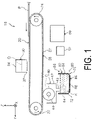
- FIG. 1 illustrates an overall configuration of the printer 10.
- the printer 10 is an example of an ejecting device, and performs recording on a sheet P, which is an example of a medium.
- Other examples of the medium include fiber.
- an X-Y-Z coordinate system illustrated in each figure is an orthogonal coordinate system.
- An X direction is a device width direction of the printer 10, and as an example, is a horizontal direction.
- a tip side of an arrow indicating a direction is defined as a +X direction, and a base end side of the arrow indicating the direction is defined as a -X direction.
- the X direction is an example of a width direction of the sheet P and a width direction of a glue belt 26 described below.
- a Y direction is a depth direction of the printer 10, and is the horizontal direction.
- the Y direction is orthogonal to the X direction.
- a tip side of an arrow indicating a direction is defined as a +Y direction, and a base end side of the arrow indicating the direction is defined as a -Y direction.
- the +Y direction is also an example of a transport direction in which the sheet P is transported.
- a Z direction is along a gravitational direction in which gravity acts.
- a tip side of an arrow indicating a direction is defined as a +Z direction
- a base end side of the arrow indicating the direction is defined as a -Z direction.
- the +Z direction is a device height direction of the printer 10, and is orthogonal to both the Y direction and the X direction.
- the printer 10 includes, as an example, a body frame (not illustrated), a transporting unit 20, a record unit 30, a cleaning unit 40, a controlling unit 50, a power source 52, and the coagulation unit 60.
- the transporting unit 20 is provided at the body frame.
- the transporting unit 20 includes a driving roller 22, a driven roller 24, the glue belt 26, and a motor (not illustrated). Then, the transporting unit 20 transports the sheet P supported by the glue belt 26 in the +Y direction, in accordance with movement of the glue belt 26 by rotation of the driving roller 22.
- the driving roller 22 is disposed downstream the driven roller 24.
- both the driving roller 22 and the driven roller 24 include a rotary shaft in the X direction. Rotation of the driving roller 22 is controlled by the controlling unit 50 described below controlling operation of the motor.
- the glue belt 26 is an example of a transport unit, and transports the sheet P in the +Y direction.
- the glue belt 26 is configured as an endless belt obtained by joining both ends of a planar plate having elasticity. Further, the glue belt 26 is wound around an outer circumferential surface of the driving roller 22 and an outer circumferential surface of the driven roller 24. In other words, the glue belt 26 is capable of transporting the sheet P by being cycled.
- a front surface 27 of the glue belt 26 has adhesiveness, and is capable of supporting and adsorbing the sheet P.
- the adhesiveness refers to a property that makes temporarily bonding with another member and peeling in a bonded state possible.
- the record unit 30 is an example of a recording unit. Furthermore, the record unit 30 is capable of recording information on the sheet P transported in the +Y direction. Specifically, the record unit 30 includes a recording head 32, which is an example of an ejecting unit, and a carriage 34 that supports the recording head 32 so that reciprocating movement is possible along the X direction. Also, the record unit 30 is disposed above the glue belt 26. The recording head 32 has a plurality of nozzles (not illustrated), and is disposed in the +Z direction with respect to the front surface 27. Additionally, the recording head 32 can perform recording on the sheet P by ejecting ink Q from the plurality of nozzles onto a recording surface of the sheet P.
- the ink Q is an example of a composition.
- the ink Q includes a black ink, and color inks different from the black ink. Examples of colors of the color ink include yellow, cyan, and magenta.
- the ink Q includes a pigment G ( FIG. 3 ) as a color material, a solvent for ensuring ejection stability and preservation stability of ink, a surfactant, a pH adjusting agent, a preservative, and an anti-mold agent.
- the pigment G of the black ink is used, as an example.
- the inorganic pigment is not particularly limited, and examples thereof include carbon black, iron oxide, titanium oxide, and silica oxide, for example.
- the organic pigment is not particularly limited, but examples thereof include, for example, a quinacridone-based pigment, a quinacridone quinone-based pigment, a dioxazine-based pigment, a phthalocyanine-based pigment, an anthrapyrimidine-based pigment, an anthanthrone-based pigment, an indanthrone-based pigment, a flavanthrone-based pigment, a perylene-based pigment, a diketopyroropyrrole-based pigment, a perinone-based pigment, a quinophthalone-based pigment, an anthraquinone-based pigment, a thioindigo-based pigment, a benzimidazolone-based pigment, an isoindolinone-based pigment, an azomethine-based pigment, and an azo-based pigment.
- a quinacridone-based pigment a quinacridone quinone-based pigment
- a dioxazine-based pigment a phthalo
- the cleaning unit 40 is an example of a cleaner unit.
- the cleaning unit 40 is disposed at a predetermined position in the -Z direction with respect to the glue belt 26.
- the cleaning unit 40 includes a cleaning tank 42 and a cleaning brush 44.
- the cleaning tank 42 is disposed in a state of opening in the +Z direction.
- An outflow pipe 43 is coupled to a bottom of the cleaning tank 42.
- a valve (not illustrated) is provided at the outflow pipe 43 so as to be able to open and close.
- a cleaning liquid C is stored in the cleaning tank 42.
- the cleaning liquid C is formed of water or an organic solvent.
- the cleaning liquid C may contain additives such as surfactants as necessary.
- the cleaning brush 44 is rotatable about a central axis along the X direction, provides the cleaning liquid C to the front surface 27 in accordance with rotation while recovering the ink Q on the front surface 27.
- the cleaning unit 40 cleans the front surface 27 of the glue belt 26 to which the ink Q adheres with the cleaning liquid C.
- a liquid containing the pigment G and the cleaning liquid C is referred to as a recovered liquid K.
- the recovered liquid K is an example of a liquid containing the pigment G and the cleaning liquid C.
- a recovered liquid before a temperature thereof is changed by a temperature change unit 80 described below is referred to as the recovered liquid K
- a recovered liquid after the temperature thereof is changed by the temperature change unit 80 is referred to as a mixture M ( FIG. 4 ), and the two are distinguished.
- Chemical composition of the mixture M is the same as chemical composition of the recovered liquid K.
- the chemical composition of the mixture M may be different from the chemical composition of the recovered liquid K.
- the chemical composition of the recovered liquid K changes during a process of heating the recovered liquid K, and as a result, the chemical composition of the mixture M may be different from the chemical composition of the recovered liquid K.
- the controlling unit 50 is configured to include a central processing unit (CPU) (not illustrated), a read only memory (ROM), a random access memory (RAM), and a storage (not illustrated), and controls operation of each unit of the printer 10.
- CPU central processing unit
- ROM read only memory
- RAM random access memory
- storage not illustrated
- the power source 52 is controlled by the controlling unit 50, and is capable of powering each unit of the printer 10. A part of power of the power source 52 is used for operation of the temperature change unit 80 described below.
- the coagulation unit 60 is an example of a coagulation device for coagulating pigments G from the recovered liquid K.
- the coagulation unit 60 includes a storage unit 70 and the temperature change unit 80.
- the coagulation unit 60 performs coagulation treatment.
- the coagulation treatment includes treatment for storing the recovered liquid K, treatment for cooling the recovered liquid K such that at least a part of the recovered liquid solidifies, and treatment for heating a solid S ( FIG. 3 ) such that the solid S generated by solidifying at least a part of the recovered liquid K liquefies. Note that, the solid S will be described below.
- the storage unit 70 has a reservoir 72, as an example.
- the reservoir 72 is open in the +Z direction, and is disposed in the -Z direction with respect to the cleaning tank 42.
- the reservoir 72 stores the recovered liquid K flowing from the cleaning tank 42 through the outflow pipe 43.
- the cleaning unit 40 and the storage unit 70 are supported by a sliding unit (not illustrated), and the sliding unit is moved in the X direction, thereby allowing extraction from the body frame or storage in the body frame.
- the temperature change unit 80 includes the power source 52, a cooling unit 82, and a heating unit 86.
- operation of the temperature change unit 80 is controlled by the controlling unit 50 to change a temperature of the recovered liquid K stored in the storage unit 70.
- the cooling unit 82 includes, as an example, a cooling plate 84 that is constituted by a Peltier element and to which a heat sink (not illustrated) is attached.
- the cooling plate 84 is attached to a side portion of the reservoir 72, as an example.
- the cooling unit 82 cools the reservoir 72.
- the cooling unit 82 can cool an inside of the reservoir 72 to a temperature lower than 0°C.
- a material constituting the reservoir 72 may be metal such as iron, stainless steel, or aluminum.
- the heating unit 86 includes, as an example, a heating plate 88 formed of a planar heating element attached to a bottom of the reservoir 72.
- the heating unit 86 heats the reservoir 72.
- the heating unit 86 heats the frozen or solidified recovered liquid K by the cooling unit 82 so as to melt, and changes a state thereof to the mixture M.
- the frozen recovered liquid K is referred to as the solid S ( FIG. 3 ).
- the temperature change unit 80 cools the recovered liquid K such that at least a part of the recovered liquid K solidifies. Furthermore, the temperature change unit 80 heats the solid S such that the solid S generated by solidifying at least a part of the recovered liquid K liquefies.
- a part of the ink Q may adhere to the front surface 27 of the glue belt 26.
- a part of the ink Q adhering to the front surface 27 is cleaned in the cleaning unit 40, recovered in the cleaning tank 42 together with the cleaning liquid C, and becomes the recovered liquid K. Then, by opening the valve (not illustrated), the recovered liquid K flows from the cleaning tank 42 to the reservoir 72, and is stored in the reservoir 72.
- the cooling unit 82 is energized by the power source 52 ( FIG. 1 ).
- a temperature of the cooling plate 84 is decreased due to a Peltier effect.
- a temperature of the recovered liquid K is decreased such that at least a part of the stored recovered liquid K solidifies.
- the stored recovered liquid K solidifies.
- Arrows in the figure represent heat movement. Since the heating unit 86 is not energized while the cooling unit 82 cools the recovered liquid K, heating is not performed.
- the outer edge part of the recovered liquid K is a part where solidification is started earlier in time compared to an inside of the recovered liquid K, and includes a part of the recovered liquid K that comes into contact with an inner wall of the reservoir 72.
- the pigments G coagulate in the solid S generated by solidifying the recovered liquid K.
- the pigments G are illustrated as a plurality of quadrangles to facilitate understanding of the pigments G, but are actually aggregate that is close to a mass.
- the pigments G in a state of being dispersed in the ink Q ( FIG. 1 ), are kept so as not to coagulate due to differences in ionization tendency.
- the pigments G are in a state of being coated with what is positively or negatively charged, and repulsive force acts on the pigments G.
- the coating of the pigments G is in a state of being removed, so it is assumed that the repulsive force is unlikely to act on the pigments G, and the pigments G coagulate.
- the heating unit 86 is energized by the power source 52 to start heating of the solid S.
- the solid S is melted by being heated by the heating unit 86 such that the solid S liquefies. This generates the mixture M. In accordance with the generation of the mixture M, the heating by the heating unit 86 is stopped.
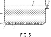
- FIG. 5 illustrates a state in which the temperature change unit 80 is removed from the reservoir 72.
- the pigments G precipitate, thereby separating a lower layer M1 containing a large amount of the pigments G, and an upper layer M2 containing a large amount of the cleaning liquids C.
- an outflow port 73 is provided in a part of the reservoir 72 to effuse the upper layer M2, which is a supernatant, and recover the upper layer M2 in a container (not illustrated). Most of the supernatant recovered in the container is composed of the cleaning liquid C.
- the pigments G are recovered from the reservoir 72 in which the pigments G precipitate.
- each of the cleaning liquid C and the pigments G can be recovered by using a sedimentation method, as an example.
- the pigments G disperse in the recovered liquid K after being used in the cleaning of the glue belt 26 ( FIG. 1 ). Furthermore, by coagulating the dispersed pigments G, the pigments G are easily recovered. This makes it easier to separate the cleaning liquid C component from the recovered liquid K, making it possible to facilitate the reuse of the cleaning liquid C for cleaning of the glue belt 26.
- the pigments G are easily separated from the recovered liquid K, thus it is possible to suppress a reduction in cleaning performance of the glue belt 26, when the cleaning liquid C is reused.
- the coagulation method, the coagulation unit 60, and the printer 10 of Modified Example 1 are substantially the same as those of Exemplary Embodiment 1, but a method of recovering the pigments G from the solid S is different from that of Exemplary Embodiment 1.
- FIG. 7 illustrates a state in which the solid S obtained by the coagulation method of Exemplary Embodiment 1 is cut by a cutting machine 89.
- the solid S is generated by cooling the recovered liquid K, points of time at which a plurality of parts of the recovered liquid K solidify differ from each other, so concentration of the pigments G in each part is not even. Many of the pigments G collect, rather than in an outer edge of the solid S, in an inside where solidification occurs later.
- a central portion SA in which these pigments G collect is cut into a cuboid shape by the cutting machine 89, as an example. Note that, of the solid S, a remaining part except the central portion SA is referred to as a remaining portion SB.
- the central portion SA a mixing ratio of the pigments G is greater compared to the remaining portion SB.
- the central portion SA as is can be discarded as the pigments G.
- the remaining portion SB has a small amount of the pigments G.
- the remaining portion SB by melting and leaving alone the remaining portion SB to precipitate the remaining pigments G, it is possible to recover the cleaning liquid C becoming the supernatant.
- the coagulation method, the coagulation unit 60, and the printer 10 of Modified Example 2 are substantially the same as those of Exemplary Embodiment 1, but a method of recovering the pigments G from the solid S is different from those of Exemplary Embodiment 1 and Modified Example 1.
- FIG. 8 illustrates a state in which the solid S ( FIG. 3 ) obtained by the coagulation method of Exemplary Embodiment 1 is pulverized by a pulverizer (not illustrated), and then screened out. Note that, the solid S is pulverized in advance into a plurality of chips each having a size that does not melt during the screening.
- a chip containing the pigments G the most is referred to as a chip A
- a chip having a lower mixing ratio of the pigments G compared to the chip A is referred to a chip B
- a chip having a lower mixing ratio of the pigments G compared to the chip B is referred to as a chip C.
- the chip A, the chip B, and the chip C illustrated in FIG. 8 are partially extracted, and are illustrated with the mixing ratios different from actual mixing ratios.
- the mixing ratio is, for example, a ratio of volume of the pigments G contained in a single chip with respect to volume of the single chip.
- the chip A, the chip B, and the chip C are screened out by a screening device 90, as an example.
- the screening device 90 includes an identification unit 92 that is capable of identifying the chip A, the chip B, and the chip C, and a separation unit 94 that separates the chip A from the chip B and the chip C, among the chip A, the chip B, and the chip C identified in the identification unit 92.
- the identification unit 92 is configured to include, for example, a camera that performs identification using near infrared rays.
- the separation unit 94 is configured to include an air nozzle (not illustrated). In addition, the separation unit 94 blows off the chip B and the chip C detected by the identification unit 92 using air. On the other hand, the chip A falls due to its own weight. As a result, the chip A is separated. There is such a method for recovering a part containing a large amount of the pigments G by pulverizing and screening the solid S.
- a coagulation method, a coagulation unit 100, and the printer 10 according to Exemplary Embodiment 2 will be specifically described. Note that, parts common to those of the coagulation method, the coagulation unit 60, and the printer 10 according to Exemplary Embodiment 1 are denoted by the same reference signs, and descriptions thereof will be omitted.
- Exemplary Embodiment 2 is different in that the coagulation unit 100 is used in the printer 10 instead of the coagulation unit 60.
- the coagulation unit 100 includes a storage unit 102, a temperature change unit 104, a separation unit 110, and a recovery tank 116.
- the storage unit 102 has the reservoir 72.
- a supply pipe 103 is coupled to a bottom of the reservoir 72.
- the temperature change unit 104 includes a cooler unit 106 and a heater unit 108.
- the cooler unit 106 cools the reservoir 72 and solidifies the recovered liquid K inside the reservoir 72.
- the heater unit 108 is energized by the power source 52 and heats the reservoir 72 to melt or liquefy the solid S ( FIG. 3 ) inside the reservoir 72.
- the separation unit 110 is coupled to an inside of the reservoir 72 via the supply pipe 103.
- the supply pipe 103 is provided with a supply pump 105.
- the separation unit 110 includes a filtration unit 112 and a centrifugation unit 114.
- the filtration unit 112 is configured to include a filter (not illustrated). In addition, the filtration unit 112 filters the mixture M generated by the solid S generated in the storage unit 102 being heated by the temperature change unit 104.
- the centrifugation unit 114 performs centrifugation to separate the pigments G from the mixture M.
- the centrifugation is performed by the centrifugation unit 114 for the mixture M after the filtration is performed in the filtration unit 112.
- An inside of the recovery tank 116 is coupled to the separation unit 110 via a discharge pipe 117.
- the discharge pipe 117 is provided with a discharge pump 118. Liquid approximately close to the cleaning liquid C after the pigments G are separated in the separation unit 110 is stored inside the recovery tank 116.
- the cooler unit 106 is energized by the power source 52 to solidify the recovered liquid K inside the reservoir 72. This causes the pigments G to coagulate in a central portion of the solid S ( FIG. 3 ). Then, the energizing the cooler unit 106 is stopped.
- the heater unit 108 heats the solid S by being energized by the power source 52. As a result, the mixture M is generated inside the reservoir 72. Then, the energizing the heater unit 108 is stopped.
- the supply pump 105 is driven to supply the mixture M inside the reservoir 72 to the separation unit 110.
- the filtration unit 112 separates the pigments G by filtering the mixture M.
- the centrifugation unit 114 further separates the pigments G by performing centrifugation for the mixture M containing a part of the remaining pigments G.
- the discharge pump 118 is driven to discharge the cleaning liquid C separated from the pigments G in the separation unit 110 into the recovery tank 116.
- a liquid after components of the pigments G are removed from the mixture M using the filtration unit 112 can be reused as the cleaning liquid C for cleaning the glue belt 26.
- a liquid after component of the pigments G are removed from the mixture M can be reused as the cleaning liquid C for cleaning the glue belt 26.
- a time for removing the components of the pigments G from the mixture M can be shortened.
- a coagulation method, a coagulation unit 120, and the printer 10 according to Exemplary Embodiment 3 will be specifically described. Note that, parts common to those of the coagulation method, the coagulation unit 60, and the printer 10 according to Exemplary Embodiment 1 are denoted by the same reference signs, and descriptions thereof will be omitted.
- Exemplary Embodiment 3 is different in that the coagulation unit 120 is used in the printer 10 instead of the coagulation unit 60.
- the coagulation unit 120 includes a storage unit 122, a temperature change unit 132, the controlling unit 50, and the power source 52.
- the controlling unit 50 in Exemplary Embodiment 3 is an example of a control unit.
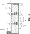
- the storage unit 122 includes, as an example, a reservoir 123, a reservoir 124, and a reservoir 125.
- the reservoir 123 is an example of a first storage unit.
- the reservoir 124 is an example of a second storage unit with respect to the reservoir 123.
- the reservoir 124 is also an example of the first storage unit with respect to the reservoir 125.
- the reservoir 125 is an example of a third storage unit.
- the reservoir 125 is also an example of the second storage unit.
- the reservoir 124 is located downstream the reservoir 123 in the +Y direction.
- the reservoir 125 is located downstream the reservoir 124 in the +Y direction.
- the reservoirs 123, 124, and 125 are each capable of storing the recovered liquid K.
- the reservoir 123 and the reservoir 124 are partitioned by a partition wall 126 that stands upright in the +Z direction.
- the reservoir 124 and the reservoir 125 are partitioned by a partition wall 127 that stands upright in the +Z direction.
- a height of the partition wall 126 in the +Z direction and a height of the partition wall 127 in the +Z direction are approximately the same height, as an example.
- the partition wall 126 and the partition wall 127 also include, as an example, components of aluminum.
- a drain pipe 128 is provided at a predetermined location in the +Z direction with respect to the reservoir 125.
- the recovered liquid K recovered after cleaning the glue belt 26 ( FIG. 1 ) flows from the drain pipe 128 to the reservoir 125 only.
- the recovered liquid K contains the pigments G ( FIG. 3 ).
- the recovered liquid K overflowing from the reservoir 125 flows into the reservoir 124.
- the reservoir 124 is full, the recovered liquid K overflowing from the reservoir 124 flows into the reservoir 123. In this manner, the recovered liquid K is stored in an order of the reservoir 125, the reservoir 124, and the reservoir 123.
- the temperature change unit 132 includes a temperature changing unit 134 for changing a temperature of the recovered liquid K stored in the reservoir 123, a temperature changing unit 137 for changing a temperature of the recovered liquid K stored in the reservoir 124, and a temperature changing unit 142 for changing a temperature of the recovered liquid K stored in the reservoir 125.
- the temperature changing unit 134 is an example of a first temperature change unit. Specifically, the temperature changing unit 134 is constituted by an endothermic plate 135, a heat dissipating plate 136, and a Peltier element (not illustrated). The Peltier element is sandwiched between the endothermic plate 135 and the heat dissipating plate 136, and is energized by the power source 52 to generate a Peltier effect.
- the heat dissipating plate 136 is attached to a side wall in the -Y direction of the reservoir 123.
- the endothermic plate 135 is exposed to an inside of the reservoir 123.
- the temperature changing unit 137 is an example of a second temperature change unit. Note that, the temperature changing unit 137 is also an example of the first temperature change unit.
- the temperature changing unit 137 is capable of discharging heat to the reservoir 123, when cooling the recovered liquid K in the reservoir 124.
- the temperature changing unit 137 is constituted by an endothermic plate 138, a heat dissipating plate 139, and a Peltier element (not illustrated).
- the Peltier element is sandwiched between the endothermic plate 138 and the heat dissipating plate 139, and is energized by the power source 52 to generate a Peltier effect.
- the heat dissipating plate 139 is attached to a surface in the +Y direction of the partition wall 126.
- the endothermic plate 138 is exposed to an inside of the reservoir 124.
- the temperature changing unit 142 is an example of a third temperature change unit. Note that, when the temperature changing unit 137 is regarded as the first temperature change unit, the temperature changing unit 142 is also an example of the second temperature change unit.
- the temperature changing unit 142 is capable of discharging heat to the reservoir 124, when the recovered liquid K is cooled in the reservoir 125.
- the temperature changing unit 142 is constituted by an endothermic plate 143, a heat dissipating plate 144, and a Peltier element (not illustrated).
- the Peltier element is sandwiched between the endothermic plate 143 and the heat dissipating plate 144, and is energized by the power source 52 to generate a Peltier effect.
- the heat dissipating plate 144 is attached to a surface in the +Y direction of the partition wall 127.
- the endothermic plate 143 is exposed to an inside of the reservoir 125.
- the endothermic plates 135, 138, and 143, and the heat dissipating plates 136, 139, and 144 may be made of metal, a thermally conductive ceramic, or the like.
- the endothermic plate 138, the heat dissipating plate 139, and the partition wall 126 are an example of members constituting a heat transfer path between the reservoir 123 and the reservoir 124.
- the endothermic plate 143, the heat dissipating plate 144, and the partition wall 127 are an example of members constituting a heat transfer path between the reservoir 124 and the reservoir 125.
- the coagulation unit 120 and the printer 10 have a heat transfer unit that transfers heat discharged from the second temperature change unit to the first storage unit.
- a thermal conduction method need not be adopted in which a plurality of members are combined as in the present exemplary embodiment.
- a thermal conduction method with a single member may be used.
- the heat discharged from the second temperature change unit may be transferred to the first storage unit by radiation, convection generated by flowing air, or the like.
- the controlling unit 50 controls operation of the temperature changing units 134, 137, and 142.
- the controlling unit 50 causes the temperature changing unit 134 to stop the operation, after causing the temperature changing unit 134 to solidify the recovered liquid K stored in the reservoir 123.
- the controlling unit 50 performs control to cause the reservoir 123 to be heated by heat discharged from the temperature changing unit 137.
- the controlling unit 50 causes the temperature changing unit 137 to stop the operation, after causing the temperature changing unit 137 to solidify the recovered liquid K stored in the reservoir 124. Furthermore, after the operation of the temperature changing unit 137 is stopped, the controlling unit 50 performs control to cause the reservoir 124 to be heated by heat discharged from the temperature changing unit 142.
- the controlling unit 50 causes the temperature changing unit 134 to stop the operation for cooling the recovered liquid K stored in the reservoir 123, after causing the temperature changing unit 134 to solidify the recovered liquid K stored in the reservoir 123, and after the operation of the temperature changing unit 134 for cooling the recovered liquid K stored in the reservoir 123 is stopped, performs control such that the temperature changing unit 137 cools the recovered liquid K stored in the reservoir 124 while discharging heat to the reservoir 123.
- the controlling unit 50 may perform control such that the temperature changing unit 134 heats the solid S in the reservoir 123, when the temperature changing unit 137 cools the recovered liquid K stored in the reservoir 124 while discharging heat to the reservoir 123.
- the controlling unit 50 may perform control to cause the temperature changing unit 134 to completely stop the operation, when the temperature changing unit 137 cools the recovered liquid K stored in the reservoir 124 while discharging heat to the reservoir 123.
- the controlling unit 50 causes the temperature changing unit 137 to stop the operation for cooling the recovered liquid K stored in the reservoir 124, after causing the temperature changing unit 137 to solidify the recovered liquid K stored in the reservoir 124, and after the operation of the temperature changing unit 137 for cooling the recovered liquid K stored in the reservoir 124 is stopped, performs control such that the temperature changing unit 142 cools the recovered liquid K stored in the reservoir 125 while discharging heat to the reservoir 124.
- the controlling unit 50 may perform control such that the temperature changing unit 137 heats the solid S in the reservoir 124, when the temperature changing unit 142 cools the recovered liquid K stored in the reservoir 125 while discharging heat to the reservoir 124.
- the controlling unit 50 may perform control to cause the temperature changing unit 137 to completely stop the operation, when the temperature changing unit 142 cools the recovered liquid K stored in the reservoir 125 while discharging heat to the reservoir 124.
- a detector may be provided that detects a degree of solidification of the recovered liquid K stored in each of the reservoirs 123, 124, and 125.
- a temperature sensor may be used as the detector.
- the controlling unit 50 can determine whether the recovered liquid K stored in each of the reservoirs 123, 124, and 125 is solidified or not.
- a sensor unit may be used as the detector that includes a vibration piece immersed in the recovered liquid K, and an actuator that vibrates the vibration piece.
- the controlling unit 50 can determine whether the recovered liquid K stored in each of the reservoirs 123, 124, and 125 is solidified or not.
- a predetermined amount of the recovered liquid K is stored in each of the reservoir 125, the reservoir 124, and the reservoir 123.
- the power source 52 energizes the temperature changing unit 134.
- a Peltier element (not illustrated) is operated, and thus heat is absorbed in the endothermic plate 135 and is dissipated in the heat dissipating plate 136.
- a temperature of the recovered liquid K in the reservoir 123 is reduced, and the recovered liquid K becomes the solid S. Then, the energizing the temperature changing unit 134 is stopped.
- the temperature changing unit 137 is energized by the power source 52.
- heat is absorbed in the endothermic plate 138, and is dissipated in the heat dissipating plate 139.
- a temperature of the recovered liquid K in the reservoir 124 is reduced, and the recovered liquid K becomes the solid S.
- the heat dissipated from the heat dissipating plate 139 moves to the solid S in the reservoir 123 via the partition wall 126. This restores the solid S in the reservoir 123 to the mixture M ( FIG. 4 ).
- the energizing the temperature changing unit 137 is stopped.
- the temperature changing unit 142 is energized by the power source 52.
- heat is absorbed in the endothermic plate 143, and is dissipated in the heat dissipating plate 144.
- a temperature of the recovered liquid K in the reservoir 125 is reduced, and the recovered liquid K becomes the solid S.
- the heat dissipated from the heat dissipating plate 144 moves to the solid S in the reservoir 124 via the partition wall 127. This restores the solid S in the reservoir 124 to the mixture M.
- the energizing the temperature changing unit 142 is stopped.
- the solidified solid S in the reservoir 123 and 124 can be restored to the mixture M, which is liquid, again, by using the heat discharged from the temperature changing units 137 and 142. This allows energy consumed by the coagulation unit 120 and the printer 10 to be reduced.
- the coagulation method, the coagulation units 60, 100, 120, and the printer 10 according to the exemplary embodiments of the present disclosure are based on the configuration described above. However, as a matter of course, modifications, omission, and the like may be made to a partial configuration without departing from the gist of the disclosure of the present application.
- the recovered liquid K when an atmospheric temperature is sufficiently low, the recovered liquid K may be solidified by leaving alone the reservoir 72 in which the recovered liquid K is stored, in the atmosphere. In this case, power required for solidification and the like are unnecessary, and thus energy for solidifying the recovered liquid K can be reduced. In addition, when the atmospheric temperature fluctuates greatly during one day, leaving the recovered liquid K alone allows thawing after solidification.
- the pigments G do not coagulate very much when the recovered liquid K is frozen in some cases. In this case, after the recovered liquid K is diluted using water or the cleaning liquid C, by solidifying the recovered liquid K, more of the pigments G can be coagulated.
- the present disclosure is not limited to a method for uniformly cooling the entire reservoir 72, and the reservoir 72 may be partially cooled by setting a time difference.
- the cooling unit 82 and the heating unit 86 may be provided at a position opposite to the reservoir 72.
- the pulverized chips A, B, and C may be separated not by free-fall, but while being transported using a belt conveyor.
- the separation unit 110 may be constituted of only the filtration unit 112 or only the centrifugation unit 114. Furthermore, after the centrifugation unit 114 is used in advance, the filtration unit 112 may be used.
- the reservoir 125 and the temperature changing unit 142 need not be present. Furthermore, the number of each of the reservoirs and the temperature changing units may be four or more.
- cooling and heating may be performed by different members, respectively, or one member may have both cooling and heating functions.
- the temperature change unit not only a temperature change unit having a cooling unit using a Peltier element, but also a temperature change unit having a heat pump may be used.
- the recovered liquid K is not limited to a recovered liquid recovered from the glue belt 26, and may be, for example, a recovered liquid recovered by cleaning a member different from the glue belt 26, such as the recording head 32.
Landscapes
- Chemical & Material Sciences (AREA)
- Chemical Kinetics & Catalysis (AREA)
- Ink Jet (AREA)
Abstract
Description
- The present application is based on, and claims priority from
JP Application Serial Number 2021-045651, filed March 19, 2021 - The present disclosure relates to a coagulation method, a coagulation device, and an ejecting device.
- In a transport belt cleaning method described in
JP 2004-136534 A - In the method described in
JP 2004-136534 A
However, a method for separating pigment from cleaning liquid containing the pigment has not been established. - In order to solve the problems described above, a coagulation method according to the present disclosure is a coagulation method for a liquid containing pigment and a cleaning liquid recovered from a liquid ejecting device, the method including storing the liquid, cooling the liquid such that at least a part of the liquid solidifies, and heating a solid generated by solidifying at least a part of the liquid in order to liquefy the solid.
- A coagulation device according to the present disclosure is a coagulation device for performing coagulation treatment for a liquid containing pigment and a cleaning liquid recovered from a liquid ejecting device, the coagulation device including a storage unit configured to store a liquid containing the pigment and the cleaning liquid, and a temperature change unit configured to change a temperature of the liquid stored in the storage unit, characterized in that the temperature change unit is configured to cool the liquid such that at least a part of the liquid solidifies, and is configured to heat a solid generated by solidifying at least a part of the liquid in order to liquefy the solid.
- An ejecting device according to the present disclosure includes a transport unit configured to transport a medium, an ejecting unit configured to eject a composition containing pigment onto the medium, a cleaner unit configured to clean, with a cleaning liquid, the transport unit to which the composition adheres, a storage unit configured to store a liquid containing the pigment and the cleaning liquid, and a temperature change unit configured to change a temperature of the liquid stored in the storage unit, characterized in that the temperature change unit is configured to cool the liquid such that the liquid solidifies, and is configured to heat a solid generated by solidifying the liquid in order to liquefy the solid.
-
-
FIG. 1 is an overall configuration diagram of a printer of Exemplary Embodiment 1. -
FIG. 2 is a schematic diagram illustrating a state in which a recovered liquid is recovered in a coagulation unit of Exemplary Embodiment 1. -
FIG. 3 is a schematic diagram illustrating a state in which the recovered liquid in the coagulation unit of Exemplary Embodiment 1 is solidified. -
FIG. 4 is a schematic diagram illustrating a state in which the recovered liquid solidified in the coagulation unit of Exemplary Embodiment 1 melts and changes to a mixture. -
FIG. 5 is a schematic diagram illustrating a state in which a cleaning liquid is recovered from the mixture in the coagulation unit of Exemplary Embodiment 1. -
FIG. 6 is a schematic diagram illustrating a state in which pigment remaining in the coagulation unit of Exemplary Embodiment 1 is recovered. -
FIG. 7 is a schematic diagram illustrating a state in which a part containing pigment is cut out from a recovered liquid solidified in a coagulation unit of Modified Example 1 of Exemplary Embodiment 1. -
FIG. 8 is a schematic diagram illustrating a state in which a recovered liquid solidified in a coagulation unit of Modified Example 2 of Exemplary Embodiment 1 is pulverized and pigment is screened out. -
FIG. 9 is a schematic diagram illustrating a state in which a mixture is separated into pigment and a cleaning liquid by filtration and centrifugation in a coagulation unit of Exemplary Embodiment 2. -
FIG. 10 is a schematic diagram illustrating a state in which a recovered liquid solidifies or melts by performing heat transfer among a plurality of adjacent reservoirs in a coagulation unit of Exemplary Embodiment 3. - Hereinafter, the present disclosure will be schematically described.
- A coagulation method according to a first aspect of the present disclosure is a coagulation method for a liquid containing pigment and a cleaning liquid recovered from a liquid ejecting device, the method including storing the liquid, cooling the liquid such that at least a part of the liquid solidifies, and heating a solid generated by solidifying at least a part of the liquid in order to liquefy the solid.
- According to the present aspect, for example, the pigment is dispersed in the liquid after being used to clean a transport unit, as an element to be cleaned by the cleaning liquid. Furthermore, since the dispersed pigment coagulates, the pigment is easily recovered. This makes it easier to separate the cleaning liquid component from the liquid, making it easier to reuse the cleaning liquid for cleaning the transport unit. Note that, an element cleaned by a cleaning liquid is not particularly limited as long as the element is an element to which pigment can adhere in accordance with operation of a liquid ejecting device, and configures the liquid ejecting device.
- A coagulation device according to a second aspect is a coagulation device for performing coagulation treatment for a liquid containing pigment and a cleaning liquid recovered from a liquid ejecting device, the coagulation device including a storage unit configured to store the liquid containing the pigment and the cleaning liquid, and a temperature change unit configured to change a temperature of a liquid stored in the storage unit, characterized in that the temperature change unit is configured to cool the liquid such that at least a part of the liquid solidifies, and is configured to heat a solid generated by solidifying at least a part of the liquid in order to liquefy the solid.
- According to the present aspect, the pigment is dispersed in the liquid, which is the cleaning liquid, after being used to clean the transport unit. Furthermore, since the dispersed pigment coagulates, the pigment is easily recovered. This makes it easier to separate the cleaning liquid component from the liquid, making it easier to reuse the cleaning liquid for cleaning the transport unit.
- A coagulation device according to a third aspect is the coagulation device according to the second aspect including a filtration unit configured to filter a mixture generated by heating the solid.
- Mixtures include both a mixture that is composed entirely and solely of liquid, and a mixture in which a part is liquid and a remaining part is a solid.
- According to the present aspect, a liquid after removing components of the pigment from the mixture using the filtration unit can be reused as the cleaning liquid for cleaning the transport unit.
- A coagulation device according to a fourth aspect is the coagulation device according to the second aspect or the third aspect including a centrifugation unit configured to perform centrifugation to separate the pigment from a mixture generated by heating the solid.
- According to the present aspect, by efficiently removing the pigment from the mixture using the centrifugation unit, the liquid after removing the components of the pigment from the mixture can be reused as the cleaning liquid for cleaning the transport unit.
- A coagulation device according to a fifth aspect is the coagulation device according to any one of the second aspect to the fourth aspect including, when the storage unit is a first storage unit, a second storage unit configured to store the liquid, when the temperature change unit that changes a temperature of the liquid stored in the first storage unit is a first temperature change unit, a second temperature change unit configured to change a temperature of the liquid stored in the second storage unit, and a control unit configured to control operation of the first temperature change unit and operation of the second temperature change unit, characterized in that the second temperature change unit is capable of discharging heat to the first storage unit when the liquid is cooled, the control unit, after causing the first temperature change unit to solidify the liquid stored in the first storage unit, causes the first temperature change unit to stop operation of cooling the liquid stored in the first storage unit, and after the operation of cooling the liquid stored in the first storage unit by the first temperature change unit is stopped, performs control such that the second temperature change unit is configured to cool the liquid stored in the second storage unit while discharging heat to the first storage unit.
- According to the present aspect, a solidified solid in the first storage unit can be restored to liquid, by using discharged heat from the second temperature change unit without heating using the first temperature change unit.
- An ejecting device according to a sixth aspect includes a transport unit configured to transport a medium, an ejecting unit configured to eject a composition containing pigment onto the medium, a cleaner unit configured to clean, with a cleaning liquid, the transport unit to which the composition adheres, a storage unit configured to store a liquid containing the pigment and the cleaning liquid, and a temperature change unit configured to change a temperature of the liquid stored in the storage unit, characterized in that the temperature change unit is configured to cool the liquid such that the liquid solidifies, and is configured to heat a solid generated by solidifying the liquid in order to liquefy the solid.
- According to the present aspect, since the dispersed pigment is coagulated, the pigment is easily recovered. This makes it easier to separate the cleaning liquid component from the liquid, making it easier to reuse the cleaning liquid for cleaning the transport unit.
- Furthermore, since the pigment is easily separated from the liquid, it is possible to suppress a reduction in cleaning performance of the transport unit, when the cleaning liquid is reused.
- Hereinafter, a coagulation method, a
coagulation unit 60, and aprinter 10 according to Exemplary Embodiment 1 of the present disclosure will be described in detail. -
FIG. 1 illustrates an overall configuration of theprinter 10. - The
printer 10 is an example of an ejecting device, and performs recording on a sheet P, which is an example of a medium. Other examples of the medium include fiber. Note that, an X-Y-Z coordinate system illustrated in each figure is an orthogonal coordinate system. - An X direction is a device width direction of the
printer 10, and as an example, is a horizontal direction. A tip side of an arrow indicating a direction is defined as a +X direction, and a base end side of the arrow indicating the direction is defined as a -X direction. Furthermore, the X direction is an example of a width direction of the sheet P and a width direction of aglue belt 26 described below. - A Y direction is a depth direction of the
printer 10, and is the horizontal direction. The Y direction is orthogonal to the X direction. A tip side of an arrow indicating a direction is defined as a +Y direction, and a base end side of the arrow indicating the direction is defined as a -Y direction. The +Y direction is also an example of a transport direction in which the sheet P is transported. - A Z direction is along a gravitational direction in which gravity acts. A tip side of an arrow indicating a direction is defined as a +Z direction, and a base end side of the arrow indicating the direction is defined as a -Z direction. The +Z direction is a device height direction of the
printer 10, and is orthogonal to both the Y direction and the X direction. - The
printer 10 includes, as an example, a body frame (not illustrated), atransporting unit 20, arecord unit 30, acleaning unit 40, a controllingunit 50, apower source 52, and thecoagulation unit 60. - The
transporting unit 20 is provided at the body frame. In particular, the transportingunit 20 includes a drivingroller 22, a drivenroller 24, theglue belt 26, and a motor (not illustrated). Then, the transportingunit 20 transports the sheet P supported by theglue belt 26 in the +Y direction, in accordance with movement of theglue belt 26 by rotation of the drivingroller 22. In the +Y direction, the drivingroller 22 is disposed downstream the drivenroller 24. In addition, both the drivingroller 22 and the drivenroller 24 include a rotary shaft in the X direction. Rotation of the drivingroller 22 is controlled by the controllingunit 50 described below controlling operation of the motor. - The
glue belt 26 is an example of a transport unit, and transports the sheet P in the +Y direction. Theglue belt 26 is configured as an endless belt obtained by joining both ends of a planar plate having elasticity. Further, theglue belt 26 is wound around an outer circumferential surface of the drivingroller 22 and an outer circumferential surface of the drivenroller 24. In other words, theglue belt 26 is capable of transporting the sheet P by being cycled. - As an example, a
front surface 27 of theglue belt 26 has adhesiveness, and is capable of supporting and adsorbing the sheet P. The adhesiveness refers to a property that makes temporarily bonding with another member and peeling in a bonded state possible. - The
record unit 30 is an example of a recording unit. Furthermore, therecord unit 30 is capable of recording information on the sheet P transported in the +Y direction. Specifically, therecord unit 30 includes arecording head 32, which is an example of an ejecting unit, and acarriage 34 that supports therecording head 32 so that reciprocating movement is possible along the X direction. Also, therecord unit 30 is disposed above theglue belt 26. Therecording head 32 has a plurality of nozzles (not illustrated), and is disposed in the +Z direction with respect to thefront surface 27. Additionally, therecording head 32 can perform recording on the sheet P by ejecting ink Q from the plurality of nozzles onto a recording surface of the sheet P. - The ink Q is an example of a composition. The ink Q includes a black ink, and color inks different from the black ink. Examples of colors of the color ink include yellow, cyan, and magenta. Specifically, the ink Q includes a pigment G (
FIG. 3 ) as a color material, a solvent for ensuring ejection stability and preservation stability of ink, a surfactant, a pH adjusting agent, a preservative, and an anti-mold agent. Note that, in the present exemplary embodiment, the pigment G of the black ink is used, as an example. - As the pigment G, both of an inorganic pigment and an organic pigment can be used. The inorganic pigment is not particularly limited, and examples thereof include carbon black, iron oxide, titanium oxide, and silica oxide, for example.
- The organic pigment is not particularly limited, but examples thereof include, for example, a quinacridone-based pigment, a quinacridone quinone-based pigment, a dioxazine-based pigment, a phthalocyanine-based pigment, an anthrapyrimidine-based pigment, an anthanthrone-based pigment, an indanthrone-based pigment, a flavanthrone-based pigment, a perylene-based pigment, a diketopyroropyrrole-based pigment, a perinone-based pigment, a quinophthalone-based pigment, an anthraquinone-based pigment, a thioindigo-based pigment, a benzimidazolone-based pigment, an isoindolinone-based pigment, an azomethine-based pigment, and an azo-based pigment.
- The
cleaning unit 40 is an example of a cleaner unit. Thecleaning unit 40 is disposed at a predetermined position in the -Z direction with respect to theglue belt 26. Specifically, thecleaning unit 40 includes acleaning tank 42 and a cleaningbrush 44. - The
cleaning tank 42 is disposed in a state of opening in the +Z direction. Anoutflow pipe 43 is coupled to a bottom of thecleaning tank 42. A valve (not illustrated) is provided at theoutflow pipe 43 so as to be able to open and close. - In the
cleaning tank 42, a cleaning liquid C is stored. For example, the cleaning liquid C is formed of water or an organic solvent. Note that, the cleaning liquid C may contain additives such as surfactants as necessary. - The cleaning
brush 44 is rotatable about a central axis along the X direction, provides the cleaning liquid C to thefront surface 27 in accordance with rotation while recovering the ink Q on thefront surface 27. - In this way, the
cleaning unit 40 cleans thefront surface 27 of theglue belt 26 to which the ink Q adheres with the cleaning liquid C. - Here, a liquid containing the pigment G and the cleaning liquid C is referred to as a recovered liquid K. The recovered liquid K is an example of a liquid containing the pigment G and the cleaning liquid C. Note that, a recovered liquid before a temperature thereof is changed by a
temperature change unit 80 described below is referred to as the recovered liquid K, and a recovered liquid after the temperature thereof is changed by thetemperature change unit 80 is referred to as a mixture M (FIG. 4 ), and the two are distinguished. Chemical composition of the mixture M is the same as chemical composition of the recovered liquid K. However, the chemical composition of the mixture M may be different from the chemical composition of the recovered liquid K. For example, the chemical composition of the recovered liquid K changes during a process of heating the recovered liquid K, and as a result, the chemical composition of the mixture M may be different from the chemical composition of the recovered liquid K. - The controlling
unit 50 is configured to include a central processing unit (CPU) (not illustrated), a read only memory (ROM), a random access memory (RAM), and a storage (not illustrated), and controls operation of each unit of theprinter 10. - The
power source 52 is controlled by the controllingunit 50, and is capable of powering each unit of theprinter 10. A part of power of thepower source 52 is used for operation of thetemperature change unit 80 described below. - The
coagulation unit 60 is an example of a coagulation device for coagulating pigments G from the recovered liquid K. Thecoagulation unit 60 includes astorage unit 70 and thetemperature change unit 80. Thecoagulation unit 60 performs coagulation treatment. The coagulation treatment includes treatment for storing the recovered liquid K, treatment for cooling the recovered liquid K such that at least a part of the recovered liquid solidifies, and treatment for heating a solid S (FIG. 3 ) such that the solid S generated by solidifying at least a part of the recovered liquid K liquefies. Note that, the solid S will be described below. - The
storage unit 70 has areservoir 72, as an example. Thereservoir 72 is open in the +Z direction, and is disposed in the -Z direction with respect to thecleaning tank 42. Thereservoir 72 stores the recovered liquid K flowing from thecleaning tank 42 through theoutflow pipe 43. - Note that, the
cleaning unit 40 and thestorage unit 70 are supported by a sliding unit (not illustrated), and the sliding unit is moved in the X direction, thereby allowing extraction from the body frame or storage in the body frame. - As an example, the
temperature change unit 80 includes thepower source 52, a coolingunit 82, and aheating unit 86. As an example, operation of thetemperature change unit 80 is controlled by the controllingunit 50 to change a temperature of the recovered liquid K stored in thestorage unit 70. - The cooling
unit 82 includes, as an example, a coolingplate 84 that is constituted by a Peltier element and to which a heat sink (not illustrated) is attached. The coolingplate 84 is attached to a side portion of thereservoir 72, as an example. When thepower source 52 energizes the coolingplate 84, the coolingunit 82 cools thereservoir 72. Note that, the coolingunit 82 can cool an inside of thereservoir 72 to a temperature lower than 0°C. A material constituting thereservoir 72 may be metal such as iron, stainless steel, or aluminum. - The
heating unit 86 includes, as an example, aheating plate 88 formed of a planar heating element attached to a bottom of thereservoir 72. When thepower source 52 energizes theheating plate 88, theheating unit 86 heats thereservoir 72. Theheating unit 86 heats the frozen or solidified recovered liquid K by the coolingunit 82 so as to melt, and changes a state thereof to the mixture M. Note that, the frozen recovered liquid K is referred to as the solid S (FIG. 3 ). - In this way, the
temperature change unit 80 cools the recovered liquid K such that at least a part of the recovered liquid K solidifies. Furthermore, thetemperature change unit 80 heats the solid S such that the solid S generated by solidifying at least a part of the recovered liquid K liquefies. - Next, an action of the coagulation method, the
coagulation unit 60, and theprinter 10 according to Exemplary Embodiment 1 will be described. - As illustrated in
FIG. 1 , after recording is performed by therecord unit 30 on the sheet P to be transported, a part of the ink Q may adhere to thefront surface 27 of theglue belt 26. For example, this applies to a case where marginless recording is performed on the sheet P, and the like. A part of the ink Q adhering to thefront surface 27 is cleaned in thecleaning unit 40, recovered in thecleaning tank 42 together with the cleaning liquid C, and becomes the recovered liquid K. Then, by opening the valve (not illustrated), the recovered liquid K flows from thecleaning tank 42 to thereservoir 72, and is stored in thereservoir 72. - As illustrated in
FIG. 2 andFIG. 3 , in a state where the recovered liquid K is stored in thereservoir 72, the coolingunit 82 is energized by the power source 52 (FIG. 1 ). A temperature of the coolingplate 84 is decreased due to a Peltier effect. As a result, a temperature of the recovered liquid K is decreased such that at least a part of the stored recovered liquid K solidifies. As a result, the stored recovered liquid K solidifies. Arrows in the figure represent heat movement. Since theheating unit 86 is not energized while the coolingunit 82 cools the recovered liquid K, heating is not performed. - Note that, when the recovered liquid K was observed during solidification, an outer edge part of the recovered liquid K was brought into a state of being close to transparent, and a state in which the pigments G (
FIG. 3 ) collect inside the recovered liquid K was seen. The outer edge part of the recovered liquid K is a part where solidification is started earlier in time compared to an inside of the recovered liquid K, and includes a part of the recovered liquid K that comes into contact with an inner wall of thereservoir 72. - As illustrated in
FIG. 3 , the pigments G coagulate in the solid S generated by solidifying the recovered liquid K. Note that, the pigments G are illustrated as a plurality of quadrangles to facilitate understanding of the pigments G, but are actually aggregate that is close to a mass. - The pigments G, in a state of being dispersed in the ink Q (
FIG. 1 ), are kept so as not to coagulate due to differences in ionization tendency. In other words, the pigments G are in a state of being coated with what is positively or negatively charged, and repulsive force acts on the pigments G. Here, when frozen, the coating of the pigments G is in a state of being removed, so it is assumed that the repulsive force is unlikely to act on the pigments G, and the pigments G coagulate. - In a state where the cooling by the cooling
unit 82 is stopped, and the solid S is accommodated in thereservoir 72, theheating unit 86 is energized by thepower source 52 to start heating of the solid S. - As illustrated in
FIG. 3 andFIG. 4 , the solid S is melted by being heated by theheating unit 86 such that the solid S liquefies. This generates the mixture M. In accordance with the generation of the mixture M, the heating by theheating unit 86 is stopped. -
FIG. 5 illustrates a state in which thetemperature change unit 80 is removed from thereservoir 72. When the mixture M is left alone, the pigments G precipitate, thereby separating a lower layer M1 containing a large amount of the pigments G, and an upper layer M2 containing a large amount of the cleaning liquids C. Here, anoutflow port 73 is provided in a part of thereservoir 72 to effuse the upper layer M2, which is a supernatant, and recover the upper layer M2 in a container (not illustrated). Most of the supernatant recovered in the container is composed of the cleaning liquid C. - As illustrated in
FIG. 6 , the pigments G are recovered from thereservoir 72 in which the pigments G precipitate. In this way, in thecoagulation unit 60 of Exemplary Embodiment 1, each of the cleaning liquid C and the pigments G can be recovered by using a sedimentation method, as an example. - As described above, according to the coagulation method and the
coagulation unit 60 of Exemplary Embodiment 1, the pigments G disperse in the recovered liquid K after being used in the cleaning of the glue belt 26 (FIG. 1 ). Furthermore, by coagulating the dispersed pigments G, the pigments G are easily recovered. This makes it easier to separate the cleaning liquid C component from the recovered liquid K, making it possible to facilitate the reuse of the cleaning liquid C for cleaning of theglue belt 26. - According to the
printer 10, the pigments G are easily separated from the recovered liquid K, thus it is possible to suppress a reduction in cleaning performance of theglue belt 26, when the cleaning liquid C is reused. - Next, a coagulation method, the
coagulation unit 60, and theprinter 10 according to Modified Example 1 of Exemplary Embodiment 1 will be described in detail. Note that, parts common to those of the coagulation method, thecoagulation unit 60, and theprinter 10 according to Exemplary Embodiment 1 are denoted by the same reference signs, and descriptions thereof will be omitted. - The coagulation method, the
coagulation unit 60, and theprinter 10 of Modified Example 1 are substantially the same as those of Exemplary Embodiment 1, but a method of recovering the pigments G from the solid S is different from that of Exemplary Embodiment 1. -
FIG. 7 illustrates a state in which the solid S obtained by the coagulation method of Exemplary Embodiment 1 is cut by a cuttingmachine 89. When the solid S is generated by cooling the recovered liquid K, points of time at which a plurality of parts of the recovered liquid K solidify differ from each other, so concentration of the pigments G in each part is not even. Many of the pigments G collect, rather than in an outer edge of the solid S, in an inside where solidification occurs later. A central portion SA in which these pigments G collect is cut into a cuboid shape by the cuttingmachine 89, as an example. Note that, of the solid S, a remaining part except the central portion SA is referred to as a remaining portion SB. - In the central portion SA, a mixing ratio of the pigments G is greater compared to the remaining portion SB. Thus, the central portion SA as is can be discarded as the pigments G.
- The remaining portion SB has a small amount of the pigments G. Thus, as an example, by melting and leaving alone the remaining portion SB to precipitate the remaining pigments G, it is possible to recover the cleaning liquid C becoming the supernatant.
- There is such a method for recovering the pigments G by cutting the coagulated pigments G from the solid S.
- Next, a coagulation method, the
coagulation unit 60, and theprinter 10 according to Modified Example 2 of Exemplary Embodiment 1 will be described in detail. Note that, parts common to those of the coagulation method, thecoagulation unit 60, and theprinter 10 according to Exemplary Embodiment 1 are denoted by the same reference signs, and descriptions thereof will be omitted. - The coagulation method, the
coagulation unit 60, and theprinter 10 of Modified Example 2 are substantially the same as those of Exemplary Embodiment 1, but a method of recovering the pigments G from the solid S is different from those of Exemplary Embodiment 1 and Modified Example 1. -
FIG. 8 illustrates a state in which the solid S (FIG. 3 ) obtained by the coagulation method of Exemplary Embodiment 1 is pulverized by a pulverizer (not illustrated), and then screened out. Note that, the solid S is pulverized in advance into a plurality of chips each having a size that does not melt during the screening. - Here, a chip containing the pigments G the most is referred to as a chip A, a chip having a lower mixing ratio of the pigments G compared to the chip A is referred to a chip B, and a chip having a lower mixing ratio of the pigments G compared to the chip B is referred to as a chip C. Note that, the chip A, the chip B, and the chip C illustrated in
FIG. 8 are partially extracted, and are illustrated with the mixing ratios different from actual mixing ratios. In addition, the mixing ratio is, for example, a ratio of volume of the pigments G contained in a single chip with respect to volume of the single chip. - The chip A, the chip B, and the chip C are screened out by a
screening device 90, as an example. - The
screening device 90 includes anidentification unit 92 that is capable of identifying the chip A, the chip B, and the chip C, and aseparation unit 94 that separates the chip A from the chip B and the chip C, among the chip A, the chip B, and the chip C identified in theidentification unit 92. - The
identification unit 92 is configured to include, for example, a camera that performs identification using near infrared rays. - The
separation unit 94 is configured to include an air nozzle (not illustrated). In addition, theseparation unit 94 blows off the chip B and the chip C detected by theidentification unit 92 using air. On the other hand, the chip A falls due to its own weight. As a result, the chip A is separated. There is such a method for recovering a part containing a large amount of the pigments G by pulverizing and screening the solid S. - Next, a coagulation method, a
coagulation unit 100, and theprinter 10 according to Exemplary Embodiment 2 will be specifically described. Note that, parts common to those of the coagulation method, thecoagulation unit 60, and theprinter 10 according to Exemplary Embodiment 1 are denoted by the same reference signs, and descriptions thereof will be omitted. - Exemplary Embodiment 2 is different in that the
coagulation unit 100 is used in theprinter 10 instead of thecoagulation unit 60. - As illustrated in
FIG. 9 , thecoagulation unit 100 includes astorage unit 102, atemperature change unit 104, aseparation unit 110, and arecovery tank 116. - The
storage unit 102 has thereservoir 72. Asupply pipe 103 is coupled to a bottom of thereservoir 72. - The
temperature change unit 104 includes acooler unit 106 and aheater unit 108. - Since a Peltier effect is generated by energization by the power source 52 (
FIG. 1 ), thecooler unit 106 cools thereservoir 72 and solidifies the recovered liquid K inside thereservoir 72. - The
heater unit 108 is energized by thepower source 52 and heats thereservoir 72 to melt or liquefy the solid S (FIG. 3 ) inside thereservoir 72. - The
separation unit 110 is coupled to an inside of thereservoir 72 via thesupply pipe 103. Thesupply pipe 103 is provided with asupply pump 105. Also, as an example, theseparation unit 110 includes afiltration unit 112 and acentrifugation unit 114. - The
filtration unit 112 is configured to include a filter (not illustrated). In addition, thefiltration unit 112 filters the mixture M generated by the solid S generated in thestorage unit 102 being heated by thetemperature change unit 104. - The
centrifugation unit 114 performs centrifugation to separate the pigments G from the mixture M. - Note that, in the
separation unit 110, the centrifugation is performed by thecentrifugation unit 114 for the mixture M after the filtration is performed in thefiltration unit 112. - An inside of the
recovery tank 116 is coupled to theseparation unit 110 via adischarge pipe 117. Thedischarge pipe 117 is provided with adischarge pump 118. Liquid approximately close to the cleaning liquid C after the pigments G are separated in theseparation unit 110 is stored inside therecovery tank 116. - Next, an action of the coagulation method, the
coagulation unit 100, and theprinter 10 of Exemplary Embodiment 2 will be described. - In the
coagulation unit 100, thecooler unit 106 is energized by thepower source 52 to solidify the recovered liquid K inside thereservoir 72. This causes the pigments G to coagulate in a central portion of the solid S (FIG. 3 ). Then, the energizing thecooler unit 106 is stopped. - Subsequently, the
heater unit 108 heats the solid S by being energized by thepower source 52. As a result, the mixture M is generated inside thereservoir 72. Then, the energizing theheater unit 108 is stopped. - The
supply pump 105 is driven to supply the mixture M inside thereservoir 72 to theseparation unit 110. - In the
separation unit 110, thefiltration unit 112 separates the pigments G by filtering the mixture M. - Subsequently, the
centrifugation unit 114 further separates the pigments G by performing centrifugation for the mixture M containing a part of the remaining pigments G. - The
discharge pump 118 is driven to discharge the cleaning liquid C separated from the pigments G in theseparation unit 110 into therecovery tank 116. - As described above, according to the coagulation method, the
coagulation unit 100, and theprinter 10 of Exemplary Embodiment 2, a liquid after components of the pigments G are removed from the mixture M using thefiltration unit 112 can be reused as the cleaning liquid C for cleaning theglue belt 26. - In addition, by efficiently removing the pigments G from the mixture M using the
centrifugation unit 114, a liquid after component of the pigments G are removed from the mixture M can be reused as the cleaning liquid C for cleaning theglue belt 26. In addition, compared to a sedimentation method, a time for removing the components of the pigments G from the mixture M can be shortened. - Next, a coagulation method, a
coagulation unit 120, and theprinter 10 according to Exemplary Embodiment 3 will be specifically described. Note that, parts common to those of the coagulation method, thecoagulation unit 60, and theprinter 10 according to Exemplary Embodiment 1 are denoted by the same reference signs, and descriptions thereof will be omitted. - Exemplary Embodiment 3 is different in that the
coagulation unit 120 is used in theprinter 10 instead of thecoagulation unit 60. - As illustrated in
FIG. 10 , thecoagulation unit 120 includes astorage unit 122, atemperature change unit 132, the controllingunit 50, and thepower source 52. The controllingunit 50 in Exemplary Embodiment 3 is an example of a control unit. - The
storage unit 122 includes, as an example, areservoir 123, areservoir 124, and areservoir 125. Thereservoir 123 is an example of a first storage unit. Thereservoir 124 is an example of a second storage unit with respect to thereservoir 123. In addition, thereservoir 124 is also an example of the first storage unit with respect to thereservoir 125. Thereservoir 125 is an example of a third storage unit. In addition, when thereservoir 124 is regarded as the first storage unit with respect to thereservoir 125, thereservoir 125 is also an example of the second storage unit. - The
reservoir 124 is located downstream thereservoir 123 in the +Y direction. Thereservoir 125 is located downstream thereservoir 124 in the +Y direction. Thereservoirs - The
reservoir 123 and thereservoir 124 are partitioned by a partition wall 126 that stands upright in the +Z direction. Thereservoir 124 and thereservoir 125 are partitioned by apartition wall 127 that stands upright in the +Z direction. A height of the partition wall 126 in the +Z direction and a height of thepartition wall 127 in the +Z direction are approximately the same height, as an example. The partition wall 126 and thepartition wall 127 also include, as an example, components of aluminum. - A
drain pipe 128 is provided at a predetermined location in the +Z direction with respect to thereservoir 125. The recovered liquid K recovered after cleaning the glue belt 26 (FIG. 1 ) flows from thedrain pipe 128 to thereservoir 125 only. The recovered liquid K contains the pigments G (FIG. 3 ). - When the
reservoir 125 is full, the recovered liquid K overflowing from thereservoir 125 flows into thereservoir 124. When thereservoir 124 is full, the recovered liquid K overflowing from thereservoir 124 flows into thereservoir 123. In this manner, the recovered liquid K is stored in an order of thereservoir 125, thereservoir 124, and thereservoir 123. - The
temperature change unit 132 includes atemperature changing unit 134 for changing a temperature of the recovered liquid K stored in thereservoir 123, a temperature changing unit 137 for changing a temperature of the recovered liquid K stored in thereservoir 124, and a temperature changing unit 142 for changing a temperature of the recovered liquid K stored in thereservoir 125. - The
temperature changing unit 134 is an example of a first temperature change unit. Specifically, thetemperature changing unit 134 is constituted by anendothermic plate 135, aheat dissipating plate 136, and a Peltier element (not illustrated). The Peltier element is sandwiched between theendothermic plate 135 and theheat dissipating plate 136, and is energized by thepower source 52 to generate a Peltier effect. Theheat dissipating plate 136 is attached to a side wall in the -Y direction of thereservoir 123. Theendothermic plate 135 is exposed to an inside of thereservoir 123. - The temperature changing unit 137 is an example of a second temperature change unit. Note that, the temperature changing unit 137 is also an example of the first temperature change unit. The temperature changing unit 137 is capable of discharging heat to the
reservoir 123, when cooling the recovered liquid K in thereservoir 124. Specifically, the temperature changing unit 137 is constituted by an endothermic plate 138, a heat dissipating plate 139, and a Peltier element (not illustrated). The Peltier element is sandwiched between the endothermic plate 138 and the heat dissipating plate 139, and is energized by thepower source 52 to generate a Peltier effect. The heat dissipating plate 139 is attached to a surface in the +Y direction of the partition wall 126. The endothermic plate 138 is exposed to an inside of thereservoir 124. - The temperature changing unit 142 is an example of a third temperature change unit. Note that, when the temperature changing unit 137 is regarded as the first temperature change unit, the temperature changing unit 142 is also an example of the second temperature change unit. The temperature changing unit 142 is capable of discharging heat to the
reservoir 124, when the recovered liquid K is cooled in thereservoir 125. Specifically, the temperature changing unit 142 is constituted by an endothermic plate 143, a heat dissipating plate 144, and a Peltier element (not illustrated). The Peltier element is sandwiched between the endothermic plate 143 and the heat dissipating plate 144, and is energized by thepower source 52 to generate a Peltier effect. The heat dissipating plate 144 is attached to a surface in the +Y direction of thepartition wall 127. The endothermic plate 143 is exposed to an inside of thereservoir 125. - Note that, the
endothermic plates 135, 138, and 143, and theheat dissipating plates 136, 139, and 144 may be made of metal, a thermally conductive ceramic, or the like. Additionally, the endothermic plate 138, the heat dissipating plate 139, and the partition wall 126 are an example of members constituting a heat transfer path between thereservoir 123 and thereservoir 124. The endothermic plate 143, the heat dissipating plate 144, and thepartition wall 127 are an example of members constituting a heat transfer path between thereservoir 124 and thereservoir 125. In other words, thecoagulation unit 120 and theprinter 10 have a heat transfer unit that transfers heat discharged from the second temperature change unit to the first storage unit. Here, for the heat transfer unit, a thermal conduction method need not be adopted in which a plurality of members are combined as in the present exemplary embodiment. For example, a thermal conduction method with a single member may be used. Further, the heat discharged from the second temperature change unit may be transferred to the first storage unit by radiation, convection generated by flowing air, or the like. - The controlling
unit 50 controls operation of thetemperature changing units 134, 137, and 142. In addition, the controllingunit 50 causes thetemperature changing unit 134 to stop the operation, after causing thetemperature changing unit 134 to solidify the recovered liquid K stored in thereservoir 123. Furthermore, after the operation of thetemperature changing unit 134 is stopped, the controllingunit 50 performs control to cause thereservoir 123 to be heated by heat discharged from the temperature changing unit 137. - The controlling
unit 50 causes the temperature changing unit 137 to stop the operation, after causing the temperature changing unit 137 to solidify the recovered liquid K stored in thereservoir 124. Furthermore, after the operation of the temperature changing unit 137 is stopped, the controllingunit 50 performs control to cause thereservoir 124 to be heated by heat discharged from the temperature changing unit 142. - In other words, the controlling
unit 50 causes thetemperature changing unit 134 to stop the operation for cooling the recovered liquid K stored in thereservoir 123, after causing thetemperature changing unit 134 to solidify the recovered liquid K stored in thereservoir 123, and after the operation of thetemperature changing unit 134 for cooling the recovered liquid K stored in thereservoir 123 is stopped, performs control such that the temperature changing unit 137 cools the recovered liquid K stored in thereservoir 124 while discharging heat to thereservoir 123. Note that, the controllingunit 50 may perform control such that thetemperature changing unit 134 heats the solid S in thereservoir 123, when the temperature changing unit 137 cools the recovered liquid K stored in thereservoir 124 while discharging heat to thereservoir 123. In addition, the controllingunit 50 may perform control to cause thetemperature changing unit 134 to completely stop the operation, when the temperature changing unit 137 cools the recovered liquid K stored in thereservoir 124 while discharging heat to thereservoir 123. - The controlling
unit 50 causes the temperature changing unit 137 to stop the operation for cooling the recovered liquid K stored in thereservoir 124, after causing the temperature changing unit 137 to solidify the recovered liquid K stored in thereservoir 124, and after the operation of the temperature changing unit 137 for cooling the recovered liquid K stored in thereservoir 124 is stopped, performs control such that the temperature changing unit 142 cools the recovered liquid K stored in thereservoir 125 while discharging heat to thereservoir 124. Note that, the controllingunit 50 may perform control such that the temperature changing unit 137 heats the solid S in thereservoir 124, when the temperature changing unit 142 cools the recovered liquid K stored in thereservoir 125 while discharging heat to thereservoir 124. In addition, the controllingunit 50 may perform control to cause the temperature changing unit 137 to completely stop the operation, when the temperature changing unit 142 cools the recovered liquid K stored in thereservoir 125 while discharging heat to thereservoir 124. - Furthermore, a detector may be provided that detects a degree of solidification of the recovered liquid K stored in each of the
reservoirs unit 50 can determine whether the recovered liquid K stored in each of thereservoirs unit 50 can determine whether the recovered liquid K stored in each of thereservoirs - Next, an action of the coagulation method, the
coagulation unit 120, and theprinter 10 of Exemplary Embodiment 3 will be described. - A predetermined amount of the recovered liquid K is stored in each of the
reservoir 125, thereservoir 124, and thereservoir 123. Here, when thereservoir 123 is substantially full, thepower source 52 energizes thetemperature changing unit 134. By this energization, a Peltier element (not illustrated) is operated, and thus heat is absorbed in theendothermic plate 135 and is dissipated in theheat dissipating plate 136. As a result, a temperature of the recovered liquid K in thereservoir 123 is reduced, and the recovered liquid K becomes the solid S. Then, the energizing thetemperature changing unit 134 is stopped. - Subsequently, the temperature changing unit 137 is energized by the
power source 52. By this energization, heat is absorbed in the endothermic plate 138, and is dissipated in the heat dissipating plate 139. As a result, a temperature of the recovered liquid K in thereservoir 124 is reduced, and the recovered liquid K becomes the solid S. At this time, the heat dissipated from the heat dissipating plate 139 moves to the solid S in thereservoir 123 via the partition wall 126. This restores the solid S in thereservoir 123 to the mixture M (FIG. 4 ). Then, the energizing the temperature changing unit 137 is stopped. - Subsequently, the temperature changing unit 142 is energized by the
power source 52. By this energization, heat is absorbed in the endothermic plate 143, and is dissipated in the heat dissipating plate 144. As a result, a temperature of the recovered liquid K in thereservoir 125 is reduced, and the recovered liquid K becomes the solid S. At this time, the heat dissipated from the heat dissipating plate 144 moves to the solid S in thereservoir 124 via thepartition wall 127. This restores the solid S in thereservoir 124 to the mixture M. Then, the energizing the temperature changing unit 142 is stopped. - As described above, according to the coagulation method, the
coagulation unit 120, and theprinter 10 of Exemplary Embodiment 3, even when heating is not performed using thetemperature changing units 134 and 137, the solidified solid S in thereservoir coagulation unit 120 and theprinter 10 to be reduced. - The coagulation method, the
coagulation units printer 10 according to the exemplary embodiments of the present disclosure are based on the configuration described above. However, as a matter of course, modifications, omission, and the like may be made to a partial configuration without departing from the gist of the disclosure of the present application. - In the
coagulation unit 60, when an atmospheric temperature is sufficiently low, the recovered liquid K may be solidified by leaving alone thereservoir 72 in which the recovered liquid K is stored, in the atmosphere. In this case, power required for solidification and the like are unnecessary, and thus energy for solidifying the recovered liquid K can be reduced. In addition, when the atmospheric temperature fluctuates greatly during one day, leaving the recovered liquid K alone allows thawing after solidification. - In the
coagulation unit 60, when concentration of the pigments G in the recovered liquid K is high, the pigments G do not coagulate very much when the recovered liquid K is frozen in some cases. In this case, after the recovered liquid K is diluted using water or the cleaning liquid C, by solidifying the recovered liquid K, more of the pigments G can be coagulated. - When cooling by the cooling
unit 82 is performed in thecoagulation unit 60, the present disclosure is not limited to a method for uniformly cooling theentire reservoir 72, and thereservoir 72 may be partially cooled by setting a time difference. - The cooling
unit 82 and theheating unit 86 may be provided at a position opposite to thereservoir 72. In Modified Example 2, the pulverized chips A, B, and C may be separated not by free-fall, but while being transported using a belt conveyor. - In the
coagulation unit 100, theseparation unit 110 may be constituted of only thefiltration unit 112 or only thecentrifugation unit 114. Furthermore, after thecentrifugation unit 114 is used in advance, thefiltration unit 112 may be used. - In the
coagulation unit 120, thereservoir 125 and the temperature changing unit 142 need not be present. Furthermore, the number of each of the reservoirs and the temperature changing units may be four or more. - In the temperature change unit, cooling and heating may be performed by different members, respectively, or one member may have both cooling and heating functions. Furthermore, as an example of the temperature change unit, not only a temperature change unit having a cooling unit using a Peltier element, but also a temperature change unit having a heat pump may be used.
- The recovered liquid K is not limited to a recovered liquid recovered from the
glue belt 26, and may be, for example, a recovered liquid recovered by cleaning a member different from theglue belt 26, such as therecording head 32. - In the cooling, both of a state in which a part of the recovered liquid K is solidified, and a state in which all of the recovered liquid K is solidified, are allowed.
Claims (5)
- A coagulation method for a liquid containing pigment and a cleaning liquid recovered from a liquid ejecting device, the method comprising:storing the liquid;cooling the liquid such that at least a part of the liquid solidifies; andheating a solid generated by solidifying at least a part of the liquid in order to liquefy the solid.
- A coagulation device for performing coagulation treatment for a liquid containing pigment and a cleaning liquid recovered from a liquid ejecting device, the coagulation device comprising:a storage unit configured to store a liquid containing the pigment and the cleaning liquid; anda temperature change unit configured to change a temperature of the liquid stored in the storage unit, characterized in thatthe temperature change unitis configured to cool the liquid such that at least a part of the liquid solidifies, andheats a solid generated by solidifying at least a part of the liquid in order to liquefy the solid.
- The coagulation device according to claim 2, comprising:
a filtration unit configured to filter a mixture generated by heating the solid. - The coagulation device according to claim 2 or 3, comprising:
a centrifugation unit configured to perform centrifugation to separate the pigment from a mixture generated by heating the solid. - The coagulation device according to any one of claims 2 to 4, comprising:a second storage unit configured to store the liquid, when the storage unit is a first storage unit;a second temperature change unit configured to change a temperature of the liquid stored in the second storage unit, when the temperature change unit that changes a temperature of the liquid stored in the first storage unit is a first temperature change unit; anda control unit configured to control operation of the first temperature change unit and operation of the second temperature change unit, characterized in thatthe second temperature change unit is configured to discharge heat to the first storage unit when the liquid is cooled,the control unit,after causing the first temperature change unit to solidify the liquid stored in the first storage unit, causes the first temperature change unit to stop operation of cooling the liquid stored in the first storage unit, andafter the operation of cooling the liquid stored in the first storage unit by the first temperature change unit is stopped, performs control such that the second temperature change unit is configured to cool the liquid stored in the second storage unit while discharging heat to the first storage unit.
Applications Claiming Priority (1)
| Application Number | Priority Date | Filing Date | Title |
|---|---|---|---|
| JP2021045651A JP7690758B2 (en) | 2021-03-19 | 2021-03-19 | Flocculation device and discharge device |
Publications (2)
| Publication Number | Publication Date |
|---|---|
| EP4059725A1 true EP4059725A1 (en) | 2022-09-21 |
| EP4059725B1 EP4059725B1 (en) | 2024-12-18 |
Family
ID=80786978
Family Applications (1)
| Application Number | Title | Priority Date | Filing Date |
|---|---|---|---|
| EP22162621.1A Active EP4059725B1 (en) | 2021-03-19 | 2022-03-17 | Coagulation method, coagulation device, and ejecting device |
Country Status (4)
| Country | Link |
|---|---|
| US (1) | US11766870B2 (en) |
| EP (1) | EP4059725B1 (en) |
| JP (1) | JP7690758B2 (en) |
| CN (1) | CN115107375B (en) |
Citations (6)
| Publication number | Priority date | Publication date | Assignee | Title |
|---|---|---|---|---|
| US5621444A (en) * | 1994-12-07 | 1997-04-15 | Hewlett-Packard Company | Controlled heating of solid ink in ink-jet printing |
| JP2004136534A (en) | 2002-10-17 | 2004-05-13 | Konica Minolta Holdings Inc | Method and equipment for cleaning conveyor belt, and ink jet recorder |
| US20070008372A1 (en) * | 2005-07-08 | 2007-01-11 | Fuji Photo Film Co., Ltd. | Ink cartridge, ink jet recording apparatus and waste-ink cartridge |
| JP2015229129A (en) * | 2014-06-04 | 2015-12-21 | 日本ゼオン株式会社 | Granulating apparatus and method for producing composite particles |
| US10500839B2 (en) * | 2017-03-06 | 2019-12-10 | Canon Kabushiki Kaisha | Inkjet printing apparatus and related printing method in which a liquid applied to a transfer member is dried before ink is discharged by a printhead |
| JP2021045651A (en) | 2009-07-10 | 2021-03-25 | メディカルトゥリー・パテント・リミテッド | Implantable lubrication device for treating human or mammal patient |
Family Cites Families (10)
| Publication number | Priority date | Publication date | Assignee | Title |
|---|---|---|---|---|
| EP1189754B1 (en) * | 1999-06-30 | 2003-02-12 | Océ Printing Systems GmbH | Method and device for printing a base material and cleaning a printing roller |
| JP3586656B2 (en) * | 2001-04-03 | 2004-11-10 | 三菱重工業株式会社 | Waste liquid regenerating apparatus and waste liquid regenerating method for printing press |
| TWI556871B (en) * | 2007-02-21 | 2016-11-11 | Musashi Engineering Inc | Ink jet forming method and coating apparatus |
| JP4960814B2 (en) * | 2007-09-18 | 2012-06-27 | 富士フイルム株式会社 | Image forming apparatus and method of controlling image forming apparatus |
| US8540338B2 (en) * | 2011-03-29 | 2013-09-24 | Eastman Kodak Company | Printhead maintenance station including station backflush |
| JP6092487B2 (en) * | 2014-09-18 | 2017-03-08 | 富士フイルム株式会社 | Droplet discharge device and nozzle surface cleaning method |
| JP6547393B2 (en) * | 2015-04-27 | 2019-07-24 | セイコーエプソン株式会社 | Liquid injection device |
| JP2017080893A (en) | 2015-10-22 | 2017-05-18 | キヤノン株式会社 | Liquid ejection apparatus and liquid ejection head cleaning method |
| JP7040361B2 (en) * | 2018-08-29 | 2022-03-23 | セイコーエプソン株式会社 | Maintenance method of liquid injection device and liquid injection device |
| CN211764264U (en) * | 2019-12-06 | 2020-10-27 | 龙利得智能科技股份有限公司 | Environmental protection is shower nozzle belt cleaning device for printing |
-
2021
- 2021-03-19 JP JP2021045651A patent/JP7690758B2/en active Active
-
2022
- 2022-03-15 CN CN202210251465.9A patent/CN115107375B/en active Active
- 2022-03-16 US US17/655,036 patent/US11766870B2/en active Active
- 2022-03-17 EP EP22162621.1A patent/EP4059725B1/en active Active
Patent Citations (6)
| Publication number | Priority date | Publication date | Assignee | Title |
|---|---|---|---|---|
| US5621444A (en) * | 1994-12-07 | 1997-04-15 | Hewlett-Packard Company | Controlled heating of solid ink in ink-jet printing |
| JP2004136534A (en) | 2002-10-17 | 2004-05-13 | Konica Minolta Holdings Inc | Method and equipment for cleaning conveyor belt, and ink jet recorder |
| US20070008372A1 (en) * | 2005-07-08 | 2007-01-11 | Fuji Photo Film Co., Ltd. | Ink cartridge, ink jet recording apparatus and waste-ink cartridge |
| JP2021045651A (en) | 2009-07-10 | 2021-03-25 | メディカルトゥリー・パテント・リミテッド | Implantable lubrication device for treating human or mammal patient |
| JP2015229129A (en) * | 2014-06-04 | 2015-12-21 | 日本ゼオン株式会社 | Granulating apparatus and method for producing composite particles |
| US10500839B2 (en) * | 2017-03-06 | 2019-12-10 | Canon Kabushiki Kaisha | Inkjet printing apparatus and related printing method in which a liquid applied to a transfer member is dried before ink is discharged by a printhead |
Also Published As
| Publication number | Publication date |
|---|---|
| JP2022144579A (en) | 2022-10-03 |
| CN115107375A (en) | 2022-09-27 |
| US11766870B2 (en) | 2023-09-26 |
| US20220297436A1 (en) | 2022-09-22 |
| CN115107375B (en) | 2025-11-21 |
| JP7690758B2 (en) | 2025-06-11 |
| EP4059725B1 (en) | 2024-12-18 |
Similar Documents
| Publication | Publication Date | Title |
|---|---|---|
| JP2021146556A (en) | Head cleaning device and liquid discharging device | |
| JP5803374B2 (en) | Recording device | |
| JP2915635B2 (en) | Ink jet recording device | |
| JP2019018388A (en) | Recording device | |
| JP2001310477A (en) | Ink tank, inkjet recording head, inkjet cartridge, and inkjet recording apparatus | |
| US20060152562A1 (en) | Ink jet recording apparatus | |
| JP2008528324A (en) | Inkjet printing apparatus having a non-contact printhead maintenance station | |
| JP2010214653A (en) | Delivering face cleaning device, liquid delivering device, and method for cleaning delivering face | |
| US20130321540A1 (en) | Ink Waste Tray Configured with One Way Filter | |
| JP2012011592A (en) | Recording apparatus and method for controlling the same | |
| KR101939407B1 (en) | A printing apparatus | |
| JP3587648B2 (en) | Ink jet recording device | |
| EP4059725B1 (en) | Coagulation method, coagulation device, and ejecting device | |
| JP2009051046A (en) | Ink jet recording head and bubble removal method | |
| JP5870560B2 (en) | Liquid ejector | |
| JP2001105628A (en) | Image forming device | |
| US9937720B2 (en) | Liquid droplet ejecting apparatus | |
| US8529015B2 (en) | Apparatus and method for removal of ink from an exterior of a printhead | |
| JPH07323554A (en) | Inkjet recording device | |
| JPH03151247A (en) | Ink-jet recorder | |
| US8591000B1 (en) | Compliant liquid path member for ink reclamation in an ink-jet printer | |
| JPH1044470A (en) | Ink jet printer | |
| JP2005231309A (en) | Liquid discharge device, image formation device and method for disposing of bubble | |
| JPH08258284A (en) | Inkjet print recorder | |
| JPH03164263A (en) | inkjet recording device |
Legal Events
| Date | Code | Title | Description |
|---|---|---|---|
| PUAI | Public reference made under article 153(3) epc to a published international application that has entered the european phase |
Free format text: ORIGINAL CODE: 0009012 |
|
| STAA | Information on the status of an ep patent application or granted ep patent |
Free format text: STATUS: THE APPLICATION HAS BEEN PUBLISHED |
|
| AK | Designated contracting states |
Kind code of ref document: A1 Designated state(s): AL AT BE BG CH CY CZ DE DK EE ES FI FR GB GR HR HU IE IS IT LI LT LU LV MC MK MT NL NO PL PT RO RS SE SI SK SM TR |
|
| STAA | Information on the status of an ep patent application or granted ep patent |
Free format text: STATUS: REQUEST FOR EXAMINATION WAS MADE |
|
| 17P | Request for examination filed |
Effective date: 20230208 |
|
| RBV | Designated contracting states (corrected) |
Designated state(s): AL AT BE BG CH CY CZ DE DK EE ES FI FR GB GR HR HU IE IS IT LI LT LU LV MC MK MT NL NO PL PT RO RS SE SI SK SM TR |
|
| GRAP | Despatch of communication of intention to grant a patent |
Free format text: ORIGINAL CODE: EPIDOSNIGR1 |
|
| STAA | Information on the status of an ep patent application or granted ep patent |
Free format text: STATUS: GRANT OF PATENT IS INTENDED |
|
| INTG | Intention to grant announced |
Effective date: 20240813 |
|
| GRAS | Grant fee paid |
Free format text: ORIGINAL CODE: EPIDOSNIGR3 |
|
| GRAA | (expected) grant |
Free format text: ORIGINAL CODE: 0009210 |
|
| STAA | Information on the status of an ep patent application or granted ep patent |
Free format text: STATUS: THE PATENT HAS BEEN GRANTED |
|
| AK | Designated contracting states |
Kind code of ref document: B1 Designated state(s): AL AT BE BG CH CY CZ DE DK EE ES FI FR GB GR HR HU IE IS IT LI LT LU LV MC MK MT NL NO PL PT RO RS SE SI SK SM TR |
|
| REG | Reference to a national code |
Ref country code: CH Ref legal event code: EP |
|
| REG | Reference to a national code |
Ref country code: DE Ref legal event code: R096 Ref document number: 602022008720 Country of ref document: DE |
|
| REG | Reference to a national code |
Ref country code: IE Ref legal event code: FG4D |
|
| REG | Reference to a national code |
Ref country code: LT Ref legal event code: MG9D |
|
| PG25 | Lapsed in a contracting state [announced via postgrant information from national office to epo] |
Ref country code: HR Free format text: LAPSE BECAUSE OF FAILURE TO SUBMIT A TRANSLATION OF THE DESCRIPTION OR TO PAY THE FEE WITHIN THE PRESCRIBED TIME-LIMIT Effective date: 20241218 |
|
| PG25 | Lapsed in a contracting state [announced via postgrant information from national office to epo] |
Ref country code: FI Free format text: LAPSE BECAUSE OF FAILURE TO SUBMIT A TRANSLATION OF THE DESCRIPTION OR TO PAY THE FEE WITHIN THE PRESCRIBED TIME-LIMIT Effective date: 20241218 |
|
| PG25 | Lapsed in a contracting state [announced via postgrant information from national office to epo] |
Ref country code: BG Free format text: LAPSE BECAUSE OF FAILURE TO SUBMIT A TRANSLATION OF THE DESCRIPTION OR TO PAY THE FEE WITHIN THE PRESCRIBED TIME-LIMIT Effective date: 20241218 |
|
| PG25 | Lapsed in a contracting state [announced via postgrant information from national office to epo] |
Ref country code: NO Free format text: LAPSE BECAUSE OF FAILURE TO SUBMIT A TRANSLATION OF THE DESCRIPTION OR TO PAY THE FEE WITHIN THE PRESCRIBED TIME-LIMIT Effective date: 20250318 |
|
| REG | Reference to a national code |
Ref country code: NL Ref legal event code: MP Effective date: 20241218 |
|
| PG25 | Lapsed in a contracting state [announced via postgrant information from national office to epo] |
Ref country code: GR Free format text: LAPSE BECAUSE OF FAILURE TO SUBMIT A TRANSLATION OF THE DESCRIPTION OR TO PAY THE FEE WITHIN THE PRESCRIBED TIME-LIMIT Effective date: 20250319 Ref country code: LV Free format text: LAPSE BECAUSE OF FAILURE TO SUBMIT A TRANSLATION OF THE DESCRIPTION OR TO PAY THE FEE WITHIN THE PRESCRIBED TIME-LIMIT Effective date: 20241218 |
|
| PG25 | Lapsed in a contracting state [announced via postgrant information from national office to epo] |
Ref country code: RS Free format text: LAPSE BECAUSE OF FAILURE TO SUBMIT A TRANSLATION OF THE DESCRIPTION OR TO PAY THE FEE WITHIN THE PRESCRIBED TIME-LIMIT Effective date: 20250318 |
|
| PG25 | Lapsed in a contracting state [announced via postgrant information from national office to epo] |
Ref country code: NL Free format text: LAPSE BECAUSE OF FAILURE TO SUBMIT A TRANSLATION OF THE DESCRIPTION OR TO PAY THE FEE WITHIN THE PRESCRIBED TIME-LIMIT Effective date: 20241218 |
|
| REG | Reference to a national code |
Ref country code: AT Ref legal event code: MK05 Ref document number: 1751972 Country of ref document: AT Kind code of ref document: T Effective date: 20241218 |
|
| PG25 | Lapsed in a contracting state [announced via postgrant information from national office to epo] |
Ref country code: SM Free format text: LAPSE BECAUSE OF FAILURE TO SUBMIT A TRANSLATION OF THE DESCRIPTION OR TO PAY THE FEE WITHIN THE PRESCRIBED TIME-LIMIT Effective date: 20241218 |
|
| PG25 | Lapsed in a contracting state [announced via postgrant information from national office to epo] |
Ref country code: PL Free format text: LAPSE BECAUSE OF FAILURE TO SUBMIT A TRANSLATION OF THE DESCRIPTION OR TO PAY THE FEE WITHIN THE PRESCRIBED TIME-LIMIT Effective date: 20241218 |
|
| PG25 | Lapsed in a contracting state [announced via postgrant information from national office to epo] |
Ref country code: ES Free format text: LAPSE BECAUSE OF FAILURE TO SUBMIT A TRANSLATION OF THE DESCRIPTION OR TO PAY THE FEE WITHIN THE PRESCRIBED TIME-LIMIT Effective date: 20241218 |
|
| PG25 | Lapsed in a contracting state [announced via postgrant information from national office to epo] |
Ref country code: IS Free format text: LAPSE BECAUSE OF FAILURE TO SUBMIT A TRANSLATION OF THE DESCRIPTION OR TO PAY THE FEE WITHIN THE PRESCRIBED TIME-LIMIT Effective date: 20250418 |
|
| PG25 | Lapsed in a contracting state [announced via postgrant information from national office to epo] |
Ref country code: PT Free format text: LAPSE BECAUSE OF FAILURE TO SUBMIT A TRANSLATION OF THE DESCRIPTION OR TO PAY THE FEE WITHIN THE PRESCRIBED TIME-LIMIT Effective date: 20250421 |
|
| PG25 | Lapsed in a contracting state [announced via postgrant information from national office to epo] |
Ref country code: EE Free format text: LAPSE BECAUSE OF FAILURE TO SUBMIT A TRANSLATION OF THE DESCRIPTION OR TO PAY THE FEE WITHIN THE PRESCRIBED TIME-LIMIT Effective date: 20241218 |
|
| PG25 | Lapsed in a contracting state [announced via postgrant information from national office to epo] |
Ref country code: AT Free format text: LAPSE BECAUSE OF FAILURE TO SUBMIT A TRANSLATION OF THE DESCRIPTION OR TO PAY THE FEE WITHIN THE PRESCRIBED TIME-LIMIT Effective date: 20241218 Ref country code: RO Free format text: LAPSE BECAUSE OF FAILURE TO SUBMIT A TRANSLATION OF THE DESCRIPTION OR TO PAY THE FEE WITHIN THE PRESCRIBED TIME-LIMIT Effective date: 20241218 |
|
| PG25 | Lapsed in a contracting state [announced via postgrant information from national office to epo] |
Ref country code: SK Free format text: LAPSE BECAUSE OF FAILURE TO SUBMIT A TRANSLATION OF THE DESCRIPTION OR TO PAY THE FEE WITHIN THE PRESCRIBED TIME-LIMIT Effective date: 20241218 |
|
| PG25 | Lapsed in a contracting state [announced via postgrant information from national office to epo] |
Ref country code: CZ Free format text: LAPSE BECAUSE OF FAILURE TO SUBMIT A TRANSLATION OF THE DESCRIPTION OR TO PAY THE FEE WITHIN THE PRESCRIBED TIME-LIMIT Effective date: 20241218 |
|
| PG25 | Lapsed in a contracting state [announced via postgrant information from national office to epo] |
Ref country code: SE Free format text: LAPSE BECAUSE OF FAILURE TO SUBMIT A TRANSLATION OF THE DESCRIPTION OR TO PAY THE FEE WITHIN THE PRESCRIBED TIME-LIMIT Effective date: 20241218 |
|
| REG | Reference to a national code |
Ref country code: DE Ref legal event code: R097 Ref document number: 602022008720 Country of ref document: DE |
|
| REG | Reference to a national code |
Ref country code: DE Ref legal event code: R119 Ref document number: 602022008720 Country of ref document: DE |
|
| PG25 | Lapsed in a contracting state [announced via postgrant information from national office to epo] |
Ref country code: DK Free format text: LAPSE BECAUSE OF FAILURE TO SUBMIT A TRANSLATION OF THE DESCRIPTION OR TO PAY THE FEE WITHIN THE PRESCRIBED TIME-LIMIT Effective date: 20241218 |
|
| PG25 | Lapsed in a contracting state [announced via postgrant information from national office to epo] |
Ref country code: MC Free format text: LAPSE BECAUSE OF FAILURE TO SUBMIT A TRANSLATION OF THE DESCRIPTION OR TO PAY THE FEE WITHIN THE PRESCRIBED TIME-LIMIT Effective date: 20241218 |
|
| PLBE | No opposition filed within time limit |
Free format text: ORIGINAL CODE: 0009261 |
|
| REG | Reference to a national code |
Ref country code: CH Ref legal event code: H13 Free format text: ST27 STATUS EVENT CODE: U-0-0-H10-H13 (AS PROVIDED BY THE NATIONAL OFFICE) Effective date: 20251024 |
|
| STAA | Information on the status of an ep patent application or granted ep patent |
Free format text: STATUS: NO OPPOSITION FILED WITHIN TIME LIMIT |
|
| PG25 | Lapsed in a contracting state [announced via postgrant information from national office to epo] |
Ref country code: LU Free format text: LAPSE BECAUSE OF NON-PAYMENT OF DUE FEES Effective date: 20250317 |
|
| 26N | No opposition filed |
Effective date: 20250919 |
|
| REG | Reference to a national code |
Ref country code: BE Ref legal event code: MM Effective date: 20250331 |
|
| PG25 | Lapsed in a contracting state [announced via postgrant information from national office to epo] |
Ref country code: DE Free format text: LAPSE BECAUSE OF NON-PAYMENT OF DUE FEES Effective date: 20251001 |
|
| PG25 | Lapsed in a contracting state [announced via postgrant information from national office to epo] |
Ref country code: FR Free format text: LAPSE BECAUSE OF NON-PAYMENT OF DUE FEES Effective date: 20250331 |
|
| PG25 | Lapsed in a contracting state [announced via postgrant information from national office to epo] |
Ref country code: BE Free format text: LAPSE BECAUSE OF NON-PAYMENT OF DUE FEES Effective date: 20250331 |
|
| PG25 | Lapsed in a contracting state [announced via postgrant information from national office to epo] |
Ref country code: CH Free format text: LAPSE BECAUSE OF NON-PAYMENT OF DUE FEES Effective date: 20250331 |
|
| PG25 | Lapsed in a contracting state [announced via postgrant information from national office to epo] |
Ref country code: IE Free format text: LAPSE BECAUSE OF NON-PAYMENT OF DUE FEES Effective date: 20250317 |
|
| PGFP | Annual fee paid to national office [announced via postgrant information from national office to epo] |
Ref country code: IT Payment date: 20260324 Year of fee payment: 5 |