EP4059664A1 - Torque wrench - Google Patents
Torque wrench Download PDFInfo
- Publication number
- EP4059664A1 EP4059664A1 EP22162518.9A EP22162518A EP4059664A1 EP 4059664 A1 EP4059664 A1 EP 4059664A1 EP 22162518 A EP22162518 A EP 22162518A EP 4059664 A1 EP4059664 A1 EP 4059664A1
- Authority
- EP
- European Patent Office
- Prior art keywords
- face
- leg
- recess
- strain gauge
- opposite
- Prior art date
- Legal status (The legal status is an assumption and is not a legal conclusion. Google has not performed a legal analysis and makes no representation as to the accuracy of the status listed.)
- Granted
Links
- 238000006243 chemical reaction Methods 0.000 description 1
- 238000005259 measurement Methods 0.000 description 1
- 238000000034 method Methods 0.000 description 1
- 238000012986 modification Methods 0.000 description 1
- 230000004048 modification Effects 0.000 description 1
Images


Classifications
-
- B—PERFORMING OPERATIONS; TRANSPORTING
- B25—HAND TOOLS; PORTABLE POWER-DRIVEN TOOLS; MANIPULATORS
- B25B—TOOLS OR BENCH DEVICES NOT OTHERWISE PROVIDED FOR, FOR FASTENING, CONNECTING, DISENGAGING OR HOLDING
- B25B13/00—Spanners; Wrenches
- B25B13/46—Spanners; Wrenches of the ratchet type, for providing a free return stroke of the handle
- B25B13/461—Spanners; Wrenches of the ratchet type, for providing a free return stroke of the handle with concentric driving and driven member
- B25B13/462—Spanners; Wrenches of the ratchet type, for providing a free return stroke of the handle with concentric driving and driven member the ratchet parts engaging in a direction radial to the tool operating axis
- B25B13/463—Spanners; Wrenches of the ratchet type, for providing a free return stroke of the handle with concentric driving and driven member the ratchet parts engaging in a direction radial to the tool operating axis a pawl engaging an externally toothed wheel
-
- B—PERFORMING OPERATIONS; TRANSPORTING
- B25—HAND TOOLS; PORTABLE POWER-DRIVEN TOOLS; MANIPULATORS
- B25B—TOOLS OR BENCH DEVICES NOT OTHERWISE PROVIDED FOR, FOR FASTENING, CONNECTING, DISENGAGING OR HOLDING
- B25B23/00—Details of, or accessories for, spanners, wrenches, screwdrivers
- B25B23/14—Arrangement of torque limiters or torque indicators in wrenches or screwdrivers
- B25B23/142—Arrangement of torque limiters or torque indicators in wrenches or screwdrivers specially adapted for hand operated wrenches or screwdrivers
- B25B23/1422—Arrangement of torque limiters or torque indicators in wrenches or screwdrivers specially adapted for hand operated wrenches or screwdrivers torque indicators or adjustable torque limiters
- B25B23/1425—Arrangement of torque limiters or torque indicators in wrenches or screwdrivers specially adapted for hand operated wrenches or screwdrivers torque indicators or adjustable torque limiters by electrical means
-
- B—PERFORMING OPERATIONS; TRANSPORTING
- B25—HAND TOOLS; PORTABLE POWER-DRIVEN TOOLS; MANIPULATORS
- B25B—TOOLS OR BENCH DEVICES NOT OTHERWISE PROVIDED FOR, FOR FASTENING, CONNECTING, DISENGAGING OR HOLDING
- B25B23/00—Details of, or accessories for, spanners, wrenches, screwdrivers
- B25B23/14—Arrangement of torque limiters or torque indicators in wrenches or screwdrivers
- B25B23/142—Arrangement of torque limiters or torque indicators in wrenches or screwdrivers specially adapted for hand operated wrenches or screwdrivers
- B25B23/1422—Arrangement of torque limiters or torque indicators in wrenches or screwdrivers specially adapted for hand operated wrenches or screwdrivers torque indicators or adjustable torque limiters
- B25B23/1427—Arrangement of torque limiters or torque indicators in wrenches or screwdrivers specially adapted for hand operated wrenches or screwdrivers torque indicators or adjustable torque limiters by mechanical means
Definitions
- the strain gauge seat 31 is provided with a second recess 314 and a third recess 315.
- the second recess 314 is arranged between the first face 312 and the third face 331 so that the first face 312 and the third face 331 are not connected with each other.
- the second recess 314 communicates with the first recess 311.
- the third recess 315 is arranged between the second face 313 and the third face 331 so that the second face 313 and the third face 331 are not connected with each other.
- the third recess 315 communicates with the first recess 311.
- the strain gauge seat 31 is provided with a first leg 34 and a second leg 35.
- the first recess 311 is arranged between the first leg 34 and the second leg 35.
- the first leg 34 and the second leg 35 are respectively integrally connected to the deformation portion 33 as a monolithic structure.
- the first face 312 is arranged at a side of the first leg 34 adjacent to the first recess 311.
- the second face 313 is arranged at a side of the second leg 35 adjacent to the first recess 311.
- the tripping mechanism 23 is an unidirectional tripping mechanism.
- the torque wrench 10 can make the torque value measured by the measuring device 30 accurate.
- the shape and structure of the strain gauge seat 31 can produce regular micro-deformation when subjected to force, thereby reducing the error of the measurement data of the strain gauge 32 to improve the accuracy of the torque value measured by the measuring device 30.
- FIGS. 4-6 show a torque wrench of a second embodiment according to the present invention.
- the second embodiment is substantially the same as the first embodiment but is mainly different from the first embodiment by that the body 20b is provided with a tripping mechanism 23b and an elastic member 24b.
- the elastic member 24b is arranged at a side of the tripping mechanism 23b opposite to the head portion 21.
- a side of the first leg 34b opposite to the tripping mechanism 23b and a side of the second leg 35b opposite to the tripping mechanism 23b are respectively abutted against the elastic member 24b.
- the third face 331b is faced to an inner periphery of the rod portion 22b.
- the strain gauge 32b is faced to the elastic member 24b.
- a side of the strain gauge seat 31b opposite to the elastic member 24b is abutted against the tripping mechanism 23b.
- the tripping mechanism 23b is provided with a receiving slot 231b.
- the abutting portion 316b is arranged at a side of the deformation portion 33b opposite to the strain gauge 32b.
- the abutting portion 316b has a spherical surface and is arranged in the receiving slot 231b. The abutting portion 316b abuts against an inner surface of the receiving slot 231b in a surface contact manner.
- FIGS. 10-12 show a torque wrench of a fourth embodiment according to the present invention.
- the fourth embodiment is substantially the same as the first embodiment but is mainly different from the first embodiment by that the strain gauge seat 31q is provided with a first leg 34q and a second leg 35q.
- the first recess 311q is arranged between the first leg 34q and the second leg 35q.
- the first leg 34q and the second leg 35q are respectively integrally connected to the deformation portion 33q as a monolithic structure.
- the first face 312q is arranged at a side of the first leg 34q adjacent to the first recess 311q.
- the second face 313q is arranged at a side of the second leg 35q adjacent to the first recess 311q.
- the first face 312q and the second face 313q are respectively connected to two opposite sides of the third face 331q.
- the tripping mechanism 23q is provided with a receiving slot 231q.
- the abutting portion 316q is arranged at a side of the first leg 34q opposite to the first recess 311q.
- the abutting portion 316q has a spherical surface and is arranged in the receiving slot 231q. The abutting portion 316q abuts against an inner surface of the receiving slot 231q in a surface contact manner.
Abstract
Description
- The present invention relates to a wrench and, more particular, to a torque wrench.
-
U.S. Patent No. 10,821,580 - In general, the operation method of the electronic torque wrench is to set the strain gauge in the wrench handle tube or other components, and use the strain gauge to obtain the torque value output by the wrench through a specific formula conversion. The above torque wrench is to set the sensing element on the outer circumference of the tubular body. However, when measuring the strain value of the torque wrench tubular body or other components that provide structural rigidity, errors are likely to occur, and it is not easy to obtain accurate torque values.
- An objective of the present invention is to provide a torque wrench, which includes a body and a measuring device. The body includes a head portion and a rod portion. An end of the rod portion is connected with the head portion. The measuring device includes a strain gauge seat and a strain gauge. The strain gauge seat is arranged in the rod portion and is provided with a first recess and a deformation portion adjacent to the first recess. The strain gauge is connected to the deformation portion.
- The present invention will become clearer in light of the following detailed description of illustrative embodiments of this invention described in connection with the drawings.
-
-
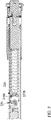
FIG. 1 is a perspective view of a torque wrench of a first embodiment according to the present invention. -
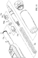
FIG. 2 is an exploded perspective view of the torque wrench of the first embodiment according to the present invention. -
FIG. 3 is a cross sectional view of the torque wrench of the first embodiment according to the present invention. -
FIG. 4 is an exploded perspective view of a torque wrench of a second embodiment according to the present invention. -
FIG. 5 is a cross sectional view of the torque wrench of the second embodiment according to the present invention. -
FIG. 6 is another cross sectional view of the torque wrench of the second embodiment according to the present invention. -
FIG. 7 is an exploded perspective view of a torque wrench of a third embodiment according to the present invention. -
FIG. 8 is a cross sectional view of the torque wrench of the third embodiment according to the present invention. -
FIG. 9 is another cross sectional view of the torque wrench of the third embodiment according to the present invention. -
FIG. 10 is a perspective view of a torque wrench of a fourth embodiment according to the present invention. -
FIG. 11 is an exploded perspective view of the torque wrench of the fourth embodiment according to the present invention. -
FIG. 12 is a cross sectional view of the torque wrench of the fourth embodiment according to the present invention. -
FIG. 13 is an exploded perspective view of a torque wrench of a fifth embodiment according to the present invention. -
FIG. 14 is a cross sectional view of the torque wrench of the fifth embodiment according to the present invention. -
FIGS. 1-3 show a torque wrench of a first embodiment according to the present invention. Thetorque wrench 10 includes abody 20 and ameasuring device 30. - The
body 20 includes ahead portion 21 and arod portion 22. An end of therod portion 22 is connected with thehead portion 21. - The
measuring device 30 includes astrain gauge seat 31 and astrain gauge 32. Thestrain gauge seat 31 is arranged in therod portion 22 and is provided with afirst recess 311 and adeformation portion 33 adjacent to thefirst recess 311. An inner periphery of thefirst recess 311 is provided with a first face 312 and a second face 313 faced to the first face 312. A side of thedeformation portion 33 adjacent to thefirst recess 311 is provided with athird face 331 arranged between the first face 312 and the second face 313. Thestrain gauge 32 is connected to thedeformation portion 33. - The
strain gauge seat 31 is provided with a second recess 314 and a third recess 315. The second recess 314 is arranged between the first face 312 and thethird face 331 so that the first face 312 and thethird face 331 are not connected with each other. The second recess 314 communicates with thefirst recess 311. The third recess 315 is arranged between the second face 313 and thethird face 331 so that the second face 313 and thethird face 331 are not connected with each other. The third recess 315 communicates with thefirst recess 311. - The
strain gauge seat 31 is provided with anabutting portion 316, and theabutting portion 316 has a raised structure with a convex arc surface. - The
strain gauge seat 31 is provided with afirst leg 34 and asecond leg 35. Thefirst recess 311 is arranged between thefirst leg 34 and thesecond leg 35. Thefirst leg 34 and thesecond leg 35 are respectively integrally connected to thedeformation portion 33 as a monolithic structure. The first face 312 is arranged at a side of thefirst leg 34 adjacent to thefirst recess 311. The second face 313 is arranged at a side of thesecond leg 35 adjacent to thefirst recess 311. - The
body 20 is provided with atripping mechanism 23 and anelastic member 24. Theelastic member 24 is arranged at a side of thetripping mechanism 23 opposite to thehead portion 21. A side of thefirst leg 34 opposite to thedeformation portion 33 and a side of thesecond leg 35 opposite to thedeformation portion 33 are respectively abutted against theelastic member 24. Thestrain gauge 32 is connected to thethird face 331 and is faced to theelastic member 24. A side of thestrain gauge seat 31 opposite to theelastic member 24 is abutted against thetripping mechanism 23. - The
tripping mechanism 23 is provided with areceiving slot 231. Theabutting portion 316 is arranged at a side of thedeformation portion 33 opposite to thestrain gauge 32. The abuttingportion 316 includes a containing slot 317 and anabutting member 318. The containing slot 317 is recessed in thedeformation portion 33. In the embodiment, theabutting member 318 is spherical, and theabutting member 318 is arranged in thereceiving slot 231 and the containing slot 317. The abuttingmember 318 simultaneously abuts against an inner surface of thereceiving slot 231 and an inner surface of the containing slot 317 in a surface contact manner. - In the embodiment, the
tripping mechanism 23 is an unidirectional tripping mechanism. - Thus, the
torque wrench 10 can make the torque value measured by the measuringdevice 30 accurate. The shape and structure of thestrain gauge seat 31 can produce regular micro-deformation when subjected to force, thereby reducing the error of the measurement data of thestrain gauge 32 to improve the accuracy of the torque value measured by the measuringdevice 30. -
FIGS. 4-6 show a torque wrench of a second embodiment according to the present invention. The second embodiment is substantially the same as the first embodiment but is mainly different from the first embodiment by that thebody 20b is provided with a trippingmechanism 23b and anelastic member 24b. Theelastic member 24b is arranged at a side of the trippingmechanism 23b opposite to thehead portion 21. A side of thefirst leg 34b opposite to the trippingmechanism 23b and a side of thesecond leg 35b opposite to the trippingmechanism 23b are respectively abutted against theelastic member 24b. Thethird face 331b is faced to an inner periphery of therod portion 22b. Thestrain gauge 32b is faced to theelastic member 24b. A side of thestrain gauge seat 31b opposite to theelastic member 24b is abutted against the trippingmechanism 23b. - The tripping
mechanism 23b is provided with a receivingslot 231b. The abuttingportion 316b is arranged at a side of thedeformation portion 33b opposite to thestrain gauge 32b. In the embodiment, the abuttingportion 316b has a spherical surface and is arranged in the receivingslot 231b. The abuttingportion 316b abuts against an inner surface of the receivingslot 231b in a surface contact manner. -
FIGS. 7-9 show a torque wrench of a third embodiment according to the present invention. The third embodiment is substantially the same as the first embodiment but is mainly different from the first embodiment by that the trippingmechanism 23g is provided with a receivingslot 231g. The abuttingportion 316g is arranged at a side of thedeformation portion 33g opposite to thestrain gauge 32g. In the embodiment, the abuttingportion 316g has a cylindrical surface. The abuttingportion 316g extends radially of therod portion 22g. The abuttingportion 316g is arranged in the receivingslot 231g. The abuttingportion 316g abuts against an inner surface of the receivingslot 231g in a surface contact manner. -
FIGS. 10-12 show a torque wrench of a fourth embodiment according to the present invention. The fourth embodiment is substantially the same as the first embodiment but is mainly different from the first embodiment by that the strain gauge seat 31q is provided with a first leg 34q and a second leg 35q. The first recess 311q is arranged between the first leg 34q and the second leg 35q. The first leg 34q and the second leg 35q are respectively integrally connected to the deformation portion 33q as a monolithic structure. Thefirst face 312q is arranged at a side of the first leg 34q adjacent to the first recess 311q. The second face 313q is arranged at a side of the second leg 35q adjacent to the first recess 311q. Thefirst face 312q and the second face 313q are respectively connected to two opposite sides of the third face 331q. - The
body 20q is provided with a trippingmechanism 23q and anelastic member 24q. Theelastic member 24q is arranged at a side of the trippingmechanism 23q opposite to thehead portion 21q. The first leg 34q is abutted against the trippingmechanism 23q. The second leg 35q is abutted against theelastic member 24q. Thestrain gauge 32q is connected to a side of the deformation portion 33q opposite to the third face 331q and is faced to an inner periphery of therod portion 22q. The third face 331q is a concave arc surface. - The tripping
mechanism 23q is provided with a receiving slot 231q. The abuttingportion 316q is arranged at a side of the first leg 34q opposite to the first recess 311q. In the embodiment, the abuttingportion 316q has a spherical surface and is arranged in the receiving slot 231q. The abuttingportion 316q abuts against an inner surface of the receiving slot 231q in a surface contact manner. -
FIGS. 13-14 show a torque wrench of a fifth embodiment according to the present invention. The fifth embodiment is substantially the same as the fourth embodiment but is mainly different from the fourth embodiment by that thebody 20r is provided with a trippingmechanism 23r, anelastic member 24r and anadjustable mechanism 25r. Theelastic member 24r is arranged at a side of the trippingmechanism 23r. Theelastic member 24r abuts against the trippingmechanism 23r. Theadjustable mechanism 25r is arranged at a side of theelastic member 24r opposite to the trippingmechanism 23r. Thefirst leg 34r is abutted against theadjustable mechanism 25r. Thesecond leg 35r is abutted against theelastic member 24r. The strain gauge 32r is connected to a side of the deformation portion 33r opposite to the third face 331r and is faced to an inner periphery of therod portion 22r. The third face 331r is a concave arc surface. - The
adjustable mechanism 25r is provided with a receiving slot 251r. The abuttingportion 316r is arranged at a side of thefirst leg 34r opposite to thefirst recess 311r. In the embodiment, the abuttingportion 316r has a spherical surface and is arranged in the receiving slot 251r. The abuttingportion 316r abuts against an inner surface of the receiving slot 251r in a surface contact manner. - Although specific embodiments have been illustrated and described, numerous modifications and variations are still possible without departing from the scope of the invention. The scope of the invention is limited by the accompanying claims.
Claims (15)
- A torque wrench (10) comprising:a body (20) including a head portion (21) and a rod portion (22), wherein an end of the rod portion (22) is connected with the head portion (21); anda measuring device (30) including a strain gauge seat (31) and a strain gauge (32), wherein the strain gauge seat (31) is arranged in the rod portion (22) and is provided with a first recess (311) and a deformation portion (33) adjacent to the first recess (311), wherein the strain gauge (32) is connected to the deformation portion (33).
- The torque wrench (10) as claimed in claim 1, wherein the strain gauge seat (31) is provided with an abutting portion (316), and wherein the abutting portion (316) has a raised structure with a convex arc surface.
- The torque wrench (10) as claimed in claim 2, wherein an inner periphery of the first recess (311) is provided with a first face (312) and a second face (313) faced to the first face (312), and wherein a side of the deformation portion (33) adjacent to the first recess (311) is provided with a third face (331) arranged between the first face (312) and the second face (313).
- The torque wrench (10) as claimed in claim 3, wherein the strain gauge seat (31q) is provided with a first leg (34q) and a second leg (35q), wherein the first recess (311q) is arranged between the first leg (34q) and the second leg (35q), wherein the first leg (34q) and the second leg (35q) are respectively integrally connected to the deformation portion (33q) as a monolithic structure, wherein the first face (312q) is arranged at a side of the first leg (34q) adjacent to the first recess (311q), wherein the second face (313q) is arranged at a side of the second leg (35q) adjacent to the first recess (311q), and wherein the first face (312q) and the second face (313q) are respectively connected to two opposite sides of the third face (331q).
- The torque wrench (10) as claimed in claim 4, wherein the body (20q) is provided with a tripping mechanism (23q) and an elastic member (24q), wherein the elastic member (24q) is arranged at a side of the tripping mechanism (23q) opposite to the head portion (21q), wherein the first leg (34q) is abutted against the tripping mechanism (23q), wherein the second leg (35q) is abutted against the elastic member (24q), wherein the strain gauge (32q) is connected to a side of the deformation portion (33q) opposite to the third face (331q) and is faced to an inner periphery of the rod portion (22q), and wherein the third face (331q) is a concave arc surface.
- The torque wrench (10) as claimed in claim 5, wherein the tripping mechanism (23q) is provided with a receiving slot (231q), wherein the abutting portion (316q) is arranged at a side of the first leg (34q) opposite to the first recess (311q), wherein the abutting portion (316q) has a spherical surface and is arranged in the receiving slot (231q), and wherein the abutting portion (316q) abuts against an inner surface of the receiving slot (231q).
- The torque wrench (10) as claimed in claim 4, wherein the body (20r) is provided with a tripping mechanism (23r), an elastic member (24r) and an adjustable mechanism (25r), wherein the elastic member (24r) is arranged at a side of the tripping mechanism (23r) opposite to the head portion (21r), wherein the elastic member (24r) abuts against the tripping mechanism (23r), wherein the adjustable mechanism (25r) is arranged at a side of the elastic member (24r) opposite to the tripping mechanism (23r), wherein the first leg (34r) is abutted against the adjustable mechanism (25r), wherein the second leg (35r) is abutted against the elastic member (24r), wherein the strain gauge (32r) is connected to a side of the deformation portion (33r) opposite to the third face (331r) and is faced to an inner periphery of the rod portion (22r), and wherein the third face (331r) is a concave arc surface.
- The torque wrench (10) as claimed in claim 7, wherein the adjustable mechanism (25r) is provided with a receiving slot (251r), wherein the abutting portion (316r) is arranged at a side of the first leg (34r) opposite to the first recess (311r), wherein the abutting portion (316r) has a spherical surface and is arranged in the receiving slot (251r), and wherein the abutting portion (316r) abuts against an inner surface of the receiving slot (251r).
- The torque wrench (10) as claimed in claim 3, wherein the strain gauge seat (31) is provided with a second recess (314) and a third recess (315), wherein the second recess (314) is arranged between the first face (312) and the third face (331) so that the first face (312) and the third face (331) are not connected with each other, wherein the second recess (314) communicates with the first recess (311), wherein the third recess (315) is arranged between the second face (313) and the third face (331) so that the second face (313) and the third face (331) are not connected with each other, and wherein the third recess (315) communicates with the first recess (311).
- The torque wrench (10) as claimed in claim 9, wherein the strain gauge seat (31) is provided with a first leg (34) and a second leg (35), wherein the first recess (311) is arranged between the first leg (34) and the second leg (35), wherein the first leg (34) and the second leg (35) are respectively integrally connected to the deformation portion (33) as a monolithic structure, wherein the first face (312) is arranged at a side of the first leg (34) adjacent to the first recess (311), and wherein the second face (313) is arranged at a side of the second leg (35) adjacent to the first recess (311).
- The torque wrench (10) as claimed in claim 10, wherein the body (20b) is provided with a tripping mechanism (23b) and an elastic member (24b), wherein the elastic member (24b) is arranged at a side of the tripping mechanism (23b) opposite to the head portion (21), wherein a side of the first leg (34b) opposite to the tripping mechanism (23b) and a side of the second leg (35b) opposite to the tripping mechanism (23b) are respectively abutted against the elastic member (24b), wherein the third face (331b) is faced to an inner periphery of the rod portion (22b), wherein the strain gauge (32b) is faced to the elastic member (24b), and wherein a side of the strain gauge seat (31b) opposite to the elastic member (24b) is abutted against the tripping mechanism (23b).
- The torque wrench (10) as claimed in claim 11, wherein the tripping mechanism (23b) is provided with a receiving slot (231b), wherein the abutting portion (316b) is arranged at a side of the deformation portion (33b) opposite to the strain gauge (32b), wherein the abutting portion (316b) is arranged in the receiving slot (231b), and wherein the abutting portion (316b) abuts against an inner surface of the receiving slot (231b).
- The torque wrench (10) as claimed in claim 10, wherein the body (20) is provided with a tripping mechanism (23) and an elastic member (24), wherein the elastic member (24) is arranged at a side of the tripping mechanism (23) opposite to the head portion (21), wherein a side of the first leg (34) opposite to the deformation portion (33) and a side of the second leg (35) opposite to the deformation portion (33) are respectively abutted against the elastic member (24), wherein the strain gauge (32) is connected to the third face (331) and is faced to the elastic member (24), and wherein a side of the strain gauge seat (31) opposite to the elastic member (24) is abutted against the tripping mechanism (23).
- The torque wrench (10) as claimed in claim 13, wherein the tripping mechanism (23) is provided with a receiving slot (231), wherein the abutting portion (316) is arranged at a side of the deformation portion (33) opposite to the strain gauge (32), wherein the abutting portion (316) includes a containing slot (317) and an abutting member (318), wherein the containing slot (317) is recessed in the deformation portion (33), wherein the abutting member (318) is spherical, wherein the abutting member (318) is arranged in the receiving slot (231) and the containing slot (317), and wherein the abutting member (318) simultaneously abuts against an inner surface of the receiving slot (231) and an inner surface of the containing slot (317) in a surface contact manner.
- The torque wrench (10) as claimed in claim 13, wherein the tripping mechanism (23g) is provided with a receiving slot (231g), wherein the abutting portion (316g) is arranged at a side of the deformation portion (33g) opposite to the strain gauge (32g), wherein the abutting portion (316g) has a cylindrical surface, wherein the abutting portion (316g) extends radially of the rod portion (22g), wherein the abutting portion (316g) is arranged in the receiving slot (231g), and wherein the abutting portion (316g) abuts against an inner surface of the receiving slot (231g).
Applications Claiming Priority (2)
| Application Number | Priority Date | Filing Date | Title |
|---|---|---|---|
| TW110109723 | 2021-03-18 | ||
| TW111105474A TWI794012B (en) | 2021-03-18 | 2022-02-15 | Torque wrench |
Publications (3)
| Publication Number | Publication Date |
|---|---|
| EP4059664A1 true EP4059664A1 (en) | 2022-09-21 |
| EP4059664C0 EP4059664C0 (en) | 2024-02-21 |
| EP4059664B1 EP4059664B1 (en) | 2024-02-21 |
Family
ID=80785041
Family Applications (1)
| Application Number | Title | Priority Date | Filing Date |
|---|---|---|---|
| EP22162518.9A Active EP4059664B1 (en) | 2021-03-18 | 2022-03-16 | Torque wrench |
Country Status (2)
| Country | Link |
|---|---|
| US (1) | US20220297268A1 (en) |
| EP (1) | EP4059664B1 (en) |
Families Citing this family (1)
| Publication number | Priority date | Publication date | Assignee | Title |
|---|---|---|---|---|
| USD981197S1 (en) * | 2021-09-08 | 2023-03-21 | Würth International Ag | Torque wrench |
Citations (5)
| Publication number | Priority date | Publication date | Assignee | Title |
|---|---|---|---|---|
| US20050072278A1 (en) * | 2003-10-03 | 2005-04-07 | Brian Cutler | Ergonomic electronic torque wrench |
| US20080127748A1 (en) * | 2006-12-04 | 2008-06-05 | National Formosa University | Electrical torque-indicating wrench |
| US20160288304A1 (en) * | 2015-04-02 | 2016-10-06 | Hsuan-Sen Shiao | Electronic Torque Wrench |
| US20180149533A1 (en) * | 2016-11-30 | 2018-05-31 | Prodrives & Motions Co., Ltd. | Axial rotation type torque sensor |
| US10821580B2 (en) | 2017-06-12 | 2020-11-03 | Kabo Tool Company | Electronic torque wrench with sensing structure |
Family Cites Families (4)
| Publication number | Priority date | Publication date | Assignee | Title |
|---|---|---|---|---|
| US7540220B2 (en) * | 2007-10-25 | 2009-06-02 | Hsuan-Sen Shiao | Electronic torque wrench having a trip unit |
| US7503228B1 (en) * | 2007-11-08 | 2009-03-17 | Chih-Ching Hsieh | Electronic torque spanner |
| US20140047957A1 (en) * | 2012-08-17 | 2014-02-20 | Jih Chun Wu | Robust Torque-Indicating Wrench |
| TWI537106B (en) * | 2013-05-20 | 2016-06-11 | Kabo Tool Co | Torque wrenches for torque correction and their torque correction methods |
-
2022
- 2022-03-14 US US17/693,842 patent/US20220297268A1/en active Pending
- 2022-03-16 EP EP22162518.9A patent/EP4059664B1/en active Active
Patent Citations (5)
| Publication number | Priority date | Publication date | Assignee | Title |
|---|---|---|---|---|
| US20050072278A1 (en) * | 2003-10-03 | 2005-04-07 | Brian Cutler | Ergonomic electronic torque wrench |
| US20080127748A1 (en) * | 2006-12-04 | 2008-06-05 | National Formosa University | Electrical torque-indicating wrench |
| US20160288304A1 (en) * | 2015-04-02 | 2016-10-06 | Hsuan-Sen Shiao | Electronic Torque Wrench |
| US20180149533A1 (en) * | 2016-11-30 | 2018-05-31 | Prodrives & Motions Co., Ltd. | Axial rotation type torque sensor |
| US10821580B2 (en) | 2017-06-12 | 2020-11-03 | Kabo Tool Company | Electronic torque wrench with sensing structure |
Also Published As
| Publication number | Publication date |
|---|---|
| EP4059664C0 (en) | 2024-02-21 |
| EP4059664B1 (en) | 2024-02-21 |
| US20220297268A1 (en) | 2022-09-22 |
Similar Documents
| Publication | Publication Date | Title |
|---|---|---|
| EP4059664A1 (en) | Torque wrench | |
| US10288504B2 (en) | Axial rotation type torque sensor | |
| US6948380B1 (en) | Torque-indicating wrench | |
| CN108072465B (en) | Three-dimensional force sensor with decoupling structure | |
| JPS61109668A (en) | Electronic torque spanner | |
| CN209979107U (en) | Torque measuring device and structural part and overload protection mechanism thereof | |
| CN111890128A (en) | Force measurement type piezoelectric fast knife servo device with three-dimensional decoupling | |
| CN109813476B (en) | Capacitive torque sensor based on structure decoupling | |
| US7478566B2 (en) | Electrical torque-indicating wrench | |
| JPH0359431A (en) | Pressure sensor and calibrating method of the same | |
| CN207095747U (en) | Small-range torque sensor | |
| JP2990327B2 (en) | Hydraulic press with thrust indicator | |
| US20020170395A1 (en) | Electronic type torsional wrench | |
| US20060011023A1 (en) | Electronic torsional tool | |
| US20060201261A1 (en) | Electronic torsional tool | |
| CN112692830A (en) | Three-dimensional angular displacement six-degree-of-freedom sensor system, measuring method and manipulator | |
| US20140207391A1 (en) | Torque socket structure | |
| US7089807B2 (en) | Low-cost high precision twisting measuring device | |
| CN217980611U (en) | Force measuring sensor | |
| CN217304121U (en) | Annular integrated pressure sensor | |
| US9630276B2 (en) | Spring compensation structure for a torque wrench | |
| CN115106969A (en) | Torque wrench | |
| JPH0337908Y2 (en) | ||
| CN216386104U (en) | Diaphragm capsule pressure gauge for measuring micropressure | |
| US3943781A (en) | Device for transmitting the displacement of a pressure-responsive element situated in pressure space |
Legal Events
| Date | Code | Title | Description |
|---|---|---|---|
| PUAI | Public reference made under article 153(3) epc to a published international application that has entered the european phase |
Free format text: ORIGINAL CODE: 0009012 |
|
| STAA | Information on the status of an ep patent application or granted ep patent |
Free format text: STATUS: THE APPLICATION HAS BEEN PUBLISHED |
|
| AK | Designated contracting states |
Kind code of ref document: A1 Designated state(s): AL AT BE BG CH CY CZ DE DK EE ES FI FR GB GR HR HU IE IS IT LI LT LU LV MC MK MT NL NO PL PT RO RS SE SI SK SM TR |
|
| STAA | Information on the status of an ep patent application or granted ep patent |
Free format text: STATUS: REQUEST FOR EXAMINATION WAS MADE |
|
| 17P | Request for examination filed |
Effective date: 20230112 |
|
| RBV | Designated contracting states (corrected) |
Designated state(s): AL AT BE BG CH CY CZ DE DK EE ES FI FR GB GR HR HU IE IS IT LI LT LU LV MC MK MT NL NO PL PT RO RS SE SI SK SM TR |
|
| STAA | Information on the status of an ep patent application or granted ep patent |
Free format text: STATUS: EXAMINATION IS IN PROGRESS |
|
| 17Q | First examination report despatched |
Effective date: 20230425 |
|
| GRAP | Despatch of communication of intention to grant a patent |
Free format text: ORIGINAL CODE: EPIDOSNIGR1 |
|
| STAA | Information on the status of an ep patent application or granted ep patent |
Free format text: STATUS: GRANT OF PATENT IS INTENDED |
|
| INTG | Intention to grant announced |
Effective date: 20231009 |
|
| GRAS | Grant fee paid |
Free format text: ORIGINAL CODE: EPIDOSNIGR3 |
|
| GRAA | (expected) grant |
Free format text: ORIGINAL CODE: 0009210 |
|
| STAA | Information on the status of an ep patent application or granted ep patent |
Free format text: STATUS: THE PATENT HAS BEEN GRANTED |
|
| AK | Designated contracting states |
Kind code of ref document: B1 Designated state(s): AL AT BE BG CH CY CZ DE DK EE ES FI FR GB GR HR HU IE IS IT LI LT LU LV MC MK MT NL NO PL PT RO RS SE SI SK SM TR |
|
| REG | Reference to a national code |
Ref country code: GB Ref legal event code: FG4D |
|
| REG | Reference to a national code |
Ref country code: CH Ref legal event code: EP |
|
| REG | Reference to a national code |
Ref country code: IE Ref legal event code: FG4D |
|
| REG | Reference to a national code |
Ref country code: DE Ref legal event code: R096 Ref document number: 602022001989 Country of ref document: DE |