EP4059647A1 - Cooling heatshield for clamshell bga rework - Google Patents
Cooling heatshield for clamshell bga rework Download PDFInfo
- Publication number
- EP4059647A1 EP4059647A1 EP21182875.1A EP21182875A EP4059647A1 EP 4059647 A1 EP4059647 A1 EP 4059647A1 EP 21182875 A EP21182875 A EP 21182875A EP 4059647 A1 EP4059647 A1 EP 4059647A1
- Authority
- EP
- European Patent Office
- Prior art keywords
- metal plate
- air inlet
- package
- heatshield
- plate
- Prior art date
- Legal status (The legal status is an assumption and is not a legal conclusion. Google has not performed a legal analysis and makes no representation as to the accuracy of the status listed.)
- Granted
Links
Images


Classifications
-
- B—PERFORMING OPERATIONS; TRANSPORTING
- B23—MACHINE TOOLS; METAL-WORKING NOT OTHERWISE PROVIDED FOR
- B23K—SOLDERING OR UNSOLDERING; WELDING; CLADDING OR PLATING BY SOLDERING OR WELDING; CUTTING BY APPLYING HEAT LOCALLY, e.g. FLAME CUTTING; WORKING BY LASER BEAM
- B23K1/00—Soldering, e.g. brazing, or unsoldering
- B23K1/0008—Soldering, e.g. brazing, or unsoldering specially adapted for particular articles or work
- B23K1/0016—Soldering of electronic components
-
- B—PERFORMING OPERATIONS; TRANSPORTING
- B23—MACHINE TOOLS; METAL-WORKING NOT OTHERWISE PROVIDED FOR
- B23K—SOLDERING OR UNSOLDERING; WELDING; CLADDING OR PLATING BY SOLDERING OR WELDING; CUTTING BY APPLYING HEAT LOCALLY, e.g. FLAME CUTTING; WORKING BY LASER BEAM
- B23K1/00—Soldering, e.g. brazing, or unsoldering
- B23K1/018—Unsoldering; Removal of melted solder or other residues
-
- B—PERFORMING OPERATIONS; TRANSPORTING
- B23—MACHINE TOOLS; METAL-WORKING NOT OTHERWISE PROVIDED FOR
- B23K—SOLDERING OR UNSOLDERING; WELDING; CLADDING OR PLATING BY SOLDERING OR WELDING; CUTTING BY APPLYING HEAT LOCALLY, e.g. FLAME CUTTING; WORKING BY LASER BEAM
- B23K3/00—Tools, devices or special appurtenances for soldering, e.g. brazing, or unsoldering, not specially adapted for particular methods
- B23K3/08—Auxiliary devices therefor
- B23K3/085—Cooling, heat sink or heat shielding means
-
- H—ELECTRICITY
- H05—ELECTRIC TECHNIQUES NOT OTHERWISE PROVIDED FOR
- H05K—PRINTED CIRCUITS; CASINGS OR CONSTRUCTIONAL DETAILS OF ELECTRIC APPARATUS; MANUFACTURE OF ASSEMBLAGES OF ELECTRICAL COMPONENTS
- H05K13/00—Apparatus or processes specially adapted for manufacturing or adjusting assemblages of electric components
- H05K13/04—Mounting of components, e.g. of leadless components
- H05K13/0486—Replacement and removal of components
-
- H—ELECTRICITY
- H10—SEMICONDUCTOR DEVICES; ELECTRIC SOLID-STATE DEVICES NOT OTHERWISE PROVIDED FOR
- H10W—GENERIC PACKAGES, INTERCONNECTIONS, CONNECTORS OR OTHER CONSTRUCTIONAL DETAILS OF DEVICES COVERED BY CLASS H10
- H10W40/00—Arrangements for thermal protection or thermal control
- H10W40/40—Arrangements for thermal protection or thermal control involving heat exchange by flowing fluids
- H10W40/43—Arrangements for thermal protection or thermal control involving heat exchange by flowing fluids by flowing gases, e.g. forced air cooling
-
- H—ELECTRICITY
- H10—SEMICONDUCTOR DEVICES; ELECTRIC SOLID-STATE DEVICES NOT OTHERWISE PROVIDED FOR
- H10W—GENERIC PACKAGES, INTERCONNECTIONS, CONNECTORS OR OTHER CONSTRUCTIONAL DETAILS OF DEVICES COVERED BY CLASS H10
- H10W70/00—Package substrates; Interposers; Redistribution layers [RDL]
- H10W70/01—Manufacture or treatment
- H10W70/05—Manufacture or treatment of insulating or insulated package substrates, or of interposers, or of redistribution layers
- H10W70/092—Adapting interconnections, e.g. making engineering charges, repairing
-
- H—ELECTRICITY
- H10—SEMICONDUCTOR DEVICES; ELECTRIC SOLID-STATE DEVICES NOT OTHERWISE PROVIDED FOR
- H10W—GENERIC PACKAGES, INTERCONNECTIONS, CONNECTORS OR OTHER CONSTRUCTIONAL DETAILS OF DEVICES COVERED BY CLASS H10
- H10W90/00—Package configurations
- H10W90/701—Package configurations characterised by the relative positions of pads or connectors relative to package parts
-
- B—PERFORMING OPERATIONS; TRANSPORTING
- B23—MACHINE TOOLS; METAL-WORKING NOT OTHERWISE PROVIDED FOR
- B23K—SOLDERING OR UNSOLDERING; WELDING; CLADDING OR PLATING BY SOLDERING OR WELDING; CUTTING BY APPLYING HEAT LOCALLY, e.g. FLAME CUTTING; WORKING BY LASER BEAM
- B23K2101/00—Articles made by soldering, welding or cutting
- B23K2101/36—Electric or electronic devices
- B23K2101/42—Printed circuits
-
- H—ELECTRICITY
- H10—SEMICONDUCTOR DEVICES; ELECTRIC SOLID-STATE DEVICES NOT OTHERWISE PROVIDED FOR
- H10W—GENERIC PACKAGES, INTERCONNECTIONS, CONNECTORS OR OTHER CONSTRUCTIONAL DETAILS OF DEVICES COVERED BY CLASS H10
- H10W40/00—Arrangements for thermal protection or thermal control
- H10W40/20—Arrangements for cooling
- H10W40/22—Arrangements for cooling characterised by their shape, e.g. having conical or cylindrical projections
- H10W40/226—Arrangements for cooling characterised by their shape, e.g. having conical or cylindrical projections characterised by projecting parts, e.g. fins to increase surface area
- H10W40/228—Arrangements for cooling characterised by their shape, e.g. having conical or cylindrical projections characterised by projecting parts, e.g. fins to increase surface area the projecting parts being wire-shaped or pin-shaped
-
- H—ELECTRICITY
- H10—SEMICONDUCTOR DEVICES; ELECTRIC SOLID-STATE DEVICES NOT OTHERWISE PROVIDED FOR
- H10W—GENERIC PACKAGES, INTERCONNECTIONS, CONNECTORS OR OTHER CONSTRUCTIONAL DETAILS OF DEVICES COVERED BY CLASS H10
- H10W40/00—Arrangements for thermal protection or thermal control
- H10W40/20—Arrangements for cooling
- H10W40/231—Arrangements for cooling characterised by their places of attachment or cooling paths
-
- H—ELECTRICITY
- H10—SEMICONDUCTOR DEVICES; ELECTRIC SOLID-STATE DEVICES NOT OTHERWISE PROVIDED FOR
- H10W—GENERIC PACKAGES, INTERCONNECTIONS, CONNECTORS OR OTHER CONSTRUCTIONAL DETAILS OF DEVICES COVERED BY CLASS H10
- H10W40/00—Arrangements for thermal protection or thermal control
- H10W40/20—Arrangements for cooling
- H10W40/231—Arrangements for cooling characterised by their places of attachment or cooling paths
- H10W40/242—Arrangements for cooling characterised by their places of attachment or cooling paths comprising thermal conductors between chips and the and the arrangements for cooling, e.g. compliant heat-spreaders
-
- H—ELECTRICITY
- H10—SEMICONDUCTOR DEVICES; ELECTRIC SOLID-STATE DEVICES NOT OTHERWISE PROVIDED FOR
- H10W—GENERIC PACKAGES, INTERCONNECTIONS, CONNECTORS OR OTHER CONSTRUCTIONAL DETAILS OF DEVICES COVERED BY CLASS H10
- H10W40/00—Arrangements for thermal protection or thermal control
- H10W40/60—Securing means for detachable heating or cooling arrangements, e.g. clamps
- H10W40/611—Bolts or screws
-
- H—ELECTRICITY
- H10—SEMICONDUCTOR DEVICES; ELECTRIC SOLID-STATE DEVICES NOT OTHERWISE PROVIDED FOR
- H10W—GENERIC PACKAGES, INTERCONNECTIONS, CONNECTORS OR OTHER CONSTRUCTIONAL DETAILS OF DEVICES COVERED BY CLASS H10
- H10W40/00—Arrangements for thermal protection or thermal control
- H10W40/70—Fillings or auxiliary members in containers or in encapsulations for thermal protection or control
- H10W40/77—Auxiliary members characterised by their shape
- H10W40/776—Arrangements for jet impingement, e.g. for spraying
-
- H—ELECTRICITY
- H10—SEMICONDUCTOR DEVICES; ELECTRIC SOLID-STATE DEVICES NOT OTHERWISE PROVIDED FOR
- H10W—GENERIC PACKAGES, INTERCONNECTIONS, CONNECTORS OR OTHER CONSTRUCTIONAL DETAILS OF DEVICES COVERED BY CLASS H10
- H10W72/00—Interconnections or connectors in packages
- H10W72/071—Connecting or disconnecting
- H10W72/073—Connecting or disconnecting of die-attach connectors
- H10W72/07351—Connecting or disconnecting of die-attach connectors characterised by changes in properties of the die-attach connectors during connecting
- H10W72/07354—Connecting or disconnecting of die-attach connectors characterised by changes in properties of the die-attach connectors during connecting changes in dispositions
-
- H—ELECTRICITY
- H10—SEMICONDUCTOR DEVICES; ELECTRIC SOLID-STATE DEVICES NOT OTHERWISE PROVIDED FOR
- H10W—GENERIC PACKAGES, INTERCONNECTIONS, CONNECTORS OR OTHER CONSTRUCTIONAL DETAILS OF DEVICES COVERED BY CLASS H10
- H10W72/00—Interconnections or connectors in packages
- H10W72/30—Die-attach connectors
- H10W72/341—Dispositions of die-attach connectors, e.g. layouts
- H10W72/347—Dispositions of multiple die-attach connectors
-
- H—ELECTRICITY
- H10—SEMICONDUCTOR DEVICES; ELECTRIC SOLID-STATE DEVICES NOT OTHERWISE PROVIDED FOR
- H10W—GENERIC PACKAGES, INTERCONNECTIONS, CONNECTORS OR OTHER CONSTRUCTIONAL DETAILS OF DEVICES COVERED BY CLASS H10
- H10W90/00—Package configurations
- H10W90/701—Package configurations characterised by the relative positions of pads or connectors relative to package parts
- H10W90/731—Package configurations characterised by the relative positions of pads or connectors relative to package parts of die-attach connectors
- H10W90/732—Package configurations characterised by the relative positions of pads or connectors relative to package parts of die-attach connectors between stacked chips
-
- H—ELECTRICITY
- H10—SEMICONDUCTOR DEVICES; ELECTRIC SOLID-STATE DEVICES NOT OTHERWISE PROVIDED FOR
- H10W—GENERIC PACKAGES, INTERCONNECTIONS, CONNECTORS OR OTHER CONSTRUCTIONAL DETAILS OF DEVICES COVERED BY CLASS H10
- H10W90/00—Package configurations
- H10W90/701—Package configurations characterised by the relative positions of pads or connectors relative to package parts
- H10W90/731—Package configurations characterised by the relative positions of pads or connectors relative to package parts of die-attach connectors
- H10W90/734—Package configurations characterised by the relative positions of pads or connectors relative to package parts of die-attach connectors between a chip and a stacked insulating package substrate, interposer or RDL
Definitions
- BGA Ball grid array
- PCB printed circuit board
- Solder joint defects may result in rework of the solder joints to be performed during manufacturing.
- the opposite-side BGA may be subjected to a reflow excursion. This may introduce solder joint defects for some BGA designs that include Via-in-Pad-Plated-Over (“VIPPO”) and non-VIPPO, or deep backdrilled BGA pads.
- VIPPO Via-in-Pad-Plated-Over
- non-VIPPO or deep backdrilled BGA pads.
- warpage-related solder joint defects such as bridging, head-in-pillow, etc.
- warpage-related solder joint defects may occur for the bottom-side BGA due to increased temperature variations within the package and solder joints during rework as compared with the surface mount reflow process.
- the present disclosure provides a heatshield with active cooling capability to a first ball grid array (“BGA") package during rework of a second BGA package of a clamshell BGA.
- the first BGA package may be the bottom-side BGA package and the second BGA package may be the top-side BGA package.
- the first and second BGA packages may be located on opposite sides of a printed circuit board ("PCB"), creating a clamshell BGA structure.
- the first BGA package may be on the side of the PCB board that faces the heatshield.
- the heatshield may include a backer plate and a metal plate. In some examples, the heatshield may also include a package pedestal.
- the backer plate may include one or more air inlet ports that are configured to be coupled to an air compressor.
- Air inlet ducting may extend from the air inlet ports through at least a portion of the backer plate.
- One or more vents may extend from the air inlet ducting to a top surface of the backer plate.
- the air inlet ducting and one or more vents may direct cooling gas towards the metal plate.
- the metal plate may be a finned metal plate.
- the heatshield may absorb thermal energy, or heat, during rework of the second BGA package.
- cooling gas may be forced into the heatshield via the air inlet port and/or air inlet ducting.
- the cooling gas may be directed towards the metal plate and the first BGA package, rather than directly towards the solder joint area.
- the PCB and second BGA may maintain the heat necessary to allow rework to occur.
- the active cooling of the heatshield using cooling gas may maintain the solder joint temperature of the first BGA package below the reflow temperature and below the solidus temperature of the solder joints.
- On aspect of the disclosure includes a system, comprising a backer plate including at least one air inlet port and a metal plate coupled to the backer plate.
- the metal plate and the backer plate may form one or more outlets.
- the at least one air inlet port may be configured to receive cooling gas to decrease a temperature of at least one of the metal plate and the backer plate.
- the cooling gas may be configured to exit the system through at least one of the one or more outlets.
- the backer plate may further include air inlet ducting connected to the at least one air inlet port, and a first plurality of vents extending from the air inlet ducting to a first surface of the backer plate.
- the system may further comprise a printed circuit board (“PCB”) and a first ball grid array (“BGA”) package positioned between the metal plate and the PCB, wherein the first BGA is coupled to a bottom surface of the PCB.
- the system may further comprise a second BGA package soldered to a top surface of the PCB. At least one of the backer plate or the metal plate may be configured to absorb heat from the first BGA package during rework of a second BGA package.
- the metal plate may be a finned metal plate.
- the cooling gas may be configured to exit the system through at least one fin of the finned metal plate.
- the system may further comprise a package pedestal coupled to the backer plate.
- the package pedestal may be positioned between the backer plate and the metal plate.
- the one or more outlets formed by the metal plate and the backer plate may extend along a top surface of the package pedestal.
- the one or more outlets may include a recess in the package pedestal extending from a center of the package pedestal to a perimeter edge of the package pedestal.
- the backer plate may further include air inlet ducting connected to the at least one air inlet port, and a first plurality of vents extending from the air inlet ducting to a first surface of the backer plate.
- the package pedestal may include a second plurality of vents extending from a bottom surface of the package pedestal to a top surface of the package pedestal, and the second plurality of vents may align with the first plurality of vents when the package pedestal is coupled to the backer plate.
- a heatshield comprising a backer plate including at least one air inlet port and air inlet duct connected to the at least one air inlet port, a package pedestal coupled to the backer plate, and a metal plate coupled to the package pedestal.
- the at least one air inlet port and the air inlet duct may be configured to receive cooling gas to decrease a temperature of the metal plate.
- the technology relates generally to a system that provides a heatshield on the top side of a first ball grid array (“BGA") package of a clamshell BGA structure to keep the solder joint temperature of the first BGA package below the reflow temperature and below the solidus temperature of the solder joint alloy such that the solder joints of the first BGA package do not become liquidus and/or soft enough to allow solder separation or other reflow-related solder defects during rework of a second BGA package.
- the clamshell BGA structure may include the first BGA package coupled to a first side of a printed circuit board (“PCB").
- the second BGA package may be coupled to a second side of the PCB opposite the first side such that the first and second BGA packages make a clamshell around the PCB.
- a bottom side of the first BGA package may be coupled to the PCB.
- the bottom side of the first BGA package may be the side of the BGA package with the solder balls.
- the heatshield on the top side of the first BGA package may prevent the solder coupling the first BGA package to the PCB from becoming liquidus during the rework of the second BGA package. This may prevent hot tears, separation, joint failure, defects, etc. of the solder joints of the first BGA package.
- the heatshield may include a backer plate and a metal plate. According to some examples, the heatshield may additionally or alternatively include a package pedestal.
- the backer plate may include one or more air inlet ports connected to interior ducting as well as one or more vents.
- the air inlet ports are configured to be coupled to an air source, such as a compressor.
- the air source may cause a cooling gas, such as air or nitrogen, to flow through air inlet ducting within the backer plate and through the vents.
- the cooling gas may come in contact with the metal plate and/or additional components of the clamshell BGA, such as the first BGA package.
- the cooling gas may become heated.
- thermal energy produced during the rework of the second BGA package may be transferred to the first BGA package, metal plate, and/or printed circuit board ("PCB").
- PCB printed circuit board
- the cooling gas reduces the thermal energy transferred to the first BGA package, metal plate, and/or PCB by cooling those components. By cooling those components, the solder of the first BGA package remains at a temperature that prevents the solder from becoming liquidus.
- the metal plate and backer plate may form one or more outlets which allow the cooling gas to exit the system.
- the cooling gas may exit the system through fins of the metal place.
- the backer plate may include one or more recesses, or outlets, extending from the center of the package pedestal to a perimeter edge of the package pedestal. The recesses may direct the heated cooling gas away from the heatshield.
- the air outlet ducting may be connected to or extend from an air outlet port.
- the air outlet port may be coupled to a vacuum such that the heated gas may be removed from the system.
- the metal plate may pull heat away from the first BGA package during the rework of the second BGA package.
- thermal energy produced by the rework of the second BGA package may be transferred to, or absorbed by, the metal plate.
- the metal plate may increase in temperature.
- the metal plate may be made of a metal that has a high thermal conductivity.
- the metal plate may be made of copper, aluminum, silver, gold, etc. A high thermal conductivity may allow the metal plate to absorb or receive more thermal energy produced during the rework of the second BGA package.
- the metal plate may be coupled to a BGA or die.
- the backer plate may be coupled to a first side of the metal plate and the BGA may be coupled to a second side of the metal plate opposite the first side.
- the metal plate may have one or more fins to maximize the surface area of the metal plate. According to some examples, increasing the surface area of the metal plate may increase the amount of contact the cooling gas has with the metal plate. By increasing the amount of contact between the metal plate and the cooling gas, the performance of the heatshield may increase as compared to a metal plate without fins. The performance of the heatshield may be how much heat is removed or dissipated by the heatshield.
- the cooling gas comes into contact with the metal plate as the cooling gas leaves the vents in the air inlet ducting.
- the cooling gas cools the metal plate that absorbed the heat from the rework of the second BGA package.
- the now heated gas may exit through one or more fins in the metal plate and/or exit through the outlets in the backer plate.
- the temperature of the first BGA package may remain below liquidus. This may prevent the solder joints of the first BGA package from melting during the rework of the second BGA package.
- the active cooling of the heatshield draws heat away from the first BGA package without inhibiting the rework process of the second BGA package.
- FIG. 1 illustrates a cross section of a clamshell ball grid array ("BGA") structure.
- the clamshell BGA structure 100 may include two BGA packages 116, 128.
- the clamshell BGA structure100 may further include a backer plate 102, a package pedestal 110, and a metal plate 114.
- the combination of the backer plate 102 and metal plate 114 may form a heatshield.
- the heatshield may additionally or alternatively include package pedestal 110.
- the backer plate 102 may include one or more air inlet ports 104 connected to air inlet ducting 106.
- Air inlet ports 104 may be configured to be coupled to a gas source, such as a compressor.
- the compressor may force cooling gas into the air inlet ports 104.
- the cooling gas may be air or nitrogen.
- Air inlet ducting 106 may extend from air inlet ports 104.
- the air inlet ducting 106 may extend inward from an edge of the backer plate 102 where air inlet port 104.
- the air inlet ducts 106 may extend from the edge of the backer plate 102 towards the center of backer plate 102. According to some examples, air inlet ducting 106 may extend past the center of backer plate 102.
- the distance air inlet ducting 106 extends along and/or through a predetermined distance of backer plate 102.
- the determined distance may be determined based on the size and/or shape of metal plate 114.
- the predetermined distance may be half, two-thirds, three-quarters, etc. of the length of the backer plate 102.
- There may be one or more vents 108 extending from air inlet ducting 106 to a first surface 134 of backer plate 102.
- the air inlet ducting 106 and vents 108 may allow the cooling gas to travel through backer plate 102 towards metal plate 114.
- the heatshield may include a package pedestal 110.
- the package pedestal 110 may be coupled to backer plate 102.
- package pedestal 110 may be integral with backer plate 102.
- Package pedestal 110 may include one or more vents 136.
- the one or more vents 136 of package pedestal 110 may align with the one or more vents 108 of backer plate 102 when package pedestal 110 is coupled to backer plate 102.
- the one or more vents 136 of package pedestal 110 are a continuation of the one or more vents 108 of backer plate 102.
- the vents 136 of package pedestal 110 direct the cooling gas towards metal plate 114.
- Package pedestal 110 may include one or more outlets 112 to allow heated gas to escape.
- the cooling gas from the compressor that is inj ected or forced into air inlet ports 104 may become heated gas once the cooling gas comes in contact with metal plate 114 during the rework process of the second BGA package 128.
- the heated gas may leave or dissipate from the heatshield by the one or more outlets 112.
- the one or more outlets 112 may be recesses or cutouts in package pedestal.
- the one or more outlets 112 may extend from metal plate 114 to edges 138 of package pedestal 110.
- the one or more outlets 112 may be channels in package pedestal 110, as best seen in Figure 2 .
- the metal plate 114 may be coupled to package pedestal 110. Alternatively, in examples where the package pedestal 110 is part of backer plate 102 or where there is no package pedestal 110, the metal plate 114 may be coupled to backer plate 102. The metal plate 114 may be coupled to the package pedestal 110 and/or backer plate 102 via one or more screws.
- the metal plate 114 may pull heat away from the first BGA package 116.
- the thermal energy produced during the rework of the second BGA package 128 may be absorbed by or transferred to the metal plate 114.
- the metal plate 114 absorbs thermal energy and/or pulls heat away from the first BGA package 116, the metal plate 114, as part of the heatshield, may prevent reflow-related solder defects from occurring with respect to the first BGA package 116 during rework of the second BGA package 128.
- the metal plate 114 may be made of a material with a high thermal conductivity. A high thermal conductivity may allow the metal plate 114 to absorb or receive a greater amount of thermal energy.
- the metal plate 114 may be made of copper, aluminum, silver, gold, etc.
- Metal plate 114 may be cooled by the cooling gas injected or forced into air inlet port 104.
- the metal plate 114 may have one or more fins 252, as shown in Figure 3 .
- the one or more fins 252 may increase the surface area of metal plate 114.
- Increasing the surface area of metal plate 114 may increase the amount of contact the cooling gas has with the metal plate 114 such that the performance of the heatshield increases as compared to a metal plate 114 without fins 252.
- the performance of the heatshield, which includes metal plate 114 may be how much heat, or thermal energy, is dissipated by the heatshield.
- the cooling gas may leave or dissipate from the heatshield by the one or more fins 252.
- the first BGA package 116 may be located between the metal plate 114 and PCB 124. As shown, the first BGA package 116 may include a stiffener ring 118 and exposed die 123. The first BGA package 116 may be soldered to a first side 140 of PCB 124 via solder balls 122.
- the second BGA package 128 may be coupled to a second side 142 of PCB 124 using solder balls 126.
- the second side 142 of PCB 124 may be opposite the first side 140 of PCB 124.
- the heatshield including the backer plate 102, metal plate 114, and/or package pedestal 110, may absorb the thermal energy during the rework of the second BGA package 128 to prevent the solder joints coupling the first BGA package 116 to PCB 124 from becoming liquidus and/or soft enough to allow reflow-related solder defects to occur.
- the solder joints coupling the first BGA package 116 to PCB 124 may include solder balls 122.
- the PCB 124 may be connected, or coupled, to the backer plate 102 via one or more posts 130.
- Posts 130 may be screw-mounted to allow for easy removal after the rework process. According to some examples, using screw mounted posts 130 may leverage tooling holes in the PCB 124.
- the tooling holes may be the holes in PCB 124 that are used to attach the heatsink.
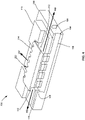
- Figures 2A and 2B illustrate a perspective view of a heatshield 200. As shown, only some of the components of clamshell BGA structure 100 is shown in heatshield 200.
- Figure 2A illustrates a perspective view of the backer plate 102, the package pedestal 110, and the metal plate 114.
- Figure 2B illustrates a perspective view of backer plate 102, the package pedestal 110, the metal plate 114, and the first BGA package 116.
- Backer plate 102 includes one or more air inlet ports 104. While three air inlet ports 104 are shown, there may be any number of air inlet ports 104. According to some examples, there may be one, four, five, etc. air inlet ports. Thus, the example of three air inlet ports 104 is only one example and is not intended to be limiting.
- the thickness of the backer plate 102 may in some examples be relational to the diameter of the air inlet ports 104.
- the thickness of the backer plate must be larger than the diameter of the air inlet ports 104. If the diameter of the air inlet ports 104 is reduced, the thickness of the backer plate 102 may be reduced also.
- the package pedestal 110 may extend from the first surface 134 of backer plate 102. According to some examples, the package pedestal 110 may be integral with backer plate 102. In some examples, package pedestal 110 may be a separate component that is coupled to backer plate 102. As shown, package pedestal 110 is coupled to backer plate 102 via a plurality of screws 250.
- the package pedestal 110 may include one or more outlets 112.
- the outlets 112 may extend, or radiate, outward from the center of package pedestal 110.
- outlets 112 may be a cut out or recess in package pedestal 110. While shown as rectangular recesses within package pedestal 110, outlets 112 may have any shape or size, such as semicircular. According to some examples, there may be an outlet 112 that extends outward to each edge, or side, of the package pedestal. In the example shown in Figure 2 , there are four outlets 112. However, this is merely one example and is not intended to be limiting, and in other examples any number of outlets may be included.
- the outlets 112 may extend non-linearly. According to some examples, the outlets 112 may form a star burst such that outlets 112 extend from the center of package pedestal 110 outwardly in all directions.
- the metal plate 114 may be coupled to package pedestal 110 between the package pedestal 110 and first BGA package 116. Metal plate 114 may be coupled to package pedestal 110 via one or more screws 254. As shown, at least a portion of metal plate 114 may extend into outlets 112.
- the metal plate 114 may include a plurality of fins 252.
- the plurality of fins 252 may increase the surface area of metal plate 114. Increasing the surface area of metal plate 114 may increase the amount of contact the cooling gas has with the metal plate. The greater the amount of cooling gas that comes in contact with metal plate 114, the better the heatshield may perform as compared to a metal plate 114 without fins.
- the heatshield may be the combination of the metal plate 114 and backer plate 102.
- cooling gas As cooling gas is forced into heatshield 200 the cooling gas may become heated once it comes in contact with metal plate 114 and/or first BGA package 116.
- the outlets 112 may direct the heated gas away from metal plate 114, first BGA package, and/or heatshield 200.
- the heated gas may also escape heatshield 200 by traveling through fins 252 and outlets 112.
- the first BGA package 116 may be layered on top of package pedestal 110 and/or metal plate 114.
- the first BGA package 116 may include a stiffener ring and/or an exposed die. Both the stiffener ring and/or exposed die may be on the side of the first BGA package 116 closest to the package pedestal 110 and metal plate 114 and, therefore, are not shown in Figure 2B .
- a thermal interface material may be used between the exposed die of the first BGA package 116 and the metal plate 114 of the heatshield to reduce thermal resistance.
- the thermal interface material may be, for example, a thermal pad or grease.
- a foam pad may be used to provide mechanical protection for the die to prevent cracking, etc. Additionally or alternatively, there may be a small air gap between the exposed die of the first BGA package 116 and the metal plate 114.
- FIG 3 illustrates a cross-sectional perspective view of the portion of the heatshield shown in Figure 2A as cooling gas is forced into heatshield 200.
- Air inlet ducting 106 extends from air inlet port 104.
- a plurality of vents 108 may extend from air inlet ducting 106 to the first surface 134 of backer plate 102. For clarity purposes, only one vent 108 of the plurality of vents 108 is labeled in Figure 3 .
- the air inlet ducting 106 and vents 108 may direct the cooling gas 360 that is injected, or forced, into the heatshield 200 towards the metal plate 114.
- Package pedestal 110 may include a plurality of vents 136. For clarity purposes, only one vent 136 of the plurality of vents 136 is labeled in Figure 3 .
- the plurality of vents 136 in package pedestal 110 may align with the plurality of vents 108 in backer plate 102.
- the vents 108, 136 may direct the cooling gas 360 towards the bottom of metal plate 114.
- cooling gas 360 may be forced into the heatshieldto cool the metal plate 114, during the rework process of the second BGA package 128.
- the cooling gas 360 may cool the metal plate 114 such that the solder joint temperature of the first BGA package 116 is kept below the reflow temperature and below the solidus temperature of the solder joint alloy. This may prevent hot tears, separation, joint failure, reflow-related defects, etc. of the solder joints of the first BGA package.
- the cooling gas 360 may be forced into heatshield 200 via an air compressor.
- the cooling gas 360 may be air or nitrogen gas.
- FIG 4 illustrates a cross-sectional perspective view of the portion of the heatshield shown in Figure 2A as heated gas leaves the heatshield 200.
- cooling gas 360 may be forced into heatshield 200 during the rework of the second BGA package 128.
- the cooling gas 360 may be heated.
- the heated gas 462 exits the heatshield 200 via one or more outlets 112.
- the heated gas 462 may leave through fins 252 of metal plate 114.
- the fins 252 of metal plate 114 may be located in outlet 112. Therefore, outlet 112 may direct the heated gas 462 away from heatshield 200.
- a heatshield that can be actively cooled during a rework process.
- the heatshield may include a backer plate, a metal plate, and/or a package pedestal.
- the backer plate may include one or more air inlet ports configured to be connected to an air compressor.
- Air inlet ducts may extend from the air inlet ports through at least a portion of the backer plate.
- a plurality of vents may extend from the air inlet ducts to a top surface of the backer plate such that the plurality of vents directs cooling gas forced into the heatshield towards the metal plate and a first BGA.
- the cooling gas may maintain the solder joint temperature of the first BGA package below the reflow temperature and below the solidus temperature of the solder joints to prevent reflow-related solder joint defects from occurring in the first BGA package during rework of a second BGA package.
Landscapes
- Engineering & Computer Science (AREA)
- Mechanical Engineering (AREA)
- Manufacturing & Machinery (AREA)
- Microelectronics & Electronic Packaging (AREA)
- Electric Connection Of Electric Components To Printed Circuits (AREA)
Abstract
Description
- Ball grid array ("BGA") packages may be used on both sides of a printed circuit board ("PCB") as PCB designs become more complex and functionally dense. As BGA packages increase in body size and complexity, the propensity for solder joint defects during assembly increases. Solder joint defects may result in rework of the solder joints to be performed during manufacturing. For a clamshell BGA configuration, if either of the top-side or bottom-side BGAs requires rework, the opposite-side BGA may be subjected to a reflow excursion. This may introduce solder joint defects for some BGA designs that include Via-in-Pad-Plated-Over ("VIPPO") and non-VIPPO, or deep backdrilled BGA pads. Alternatively, warpage-related solder joint defects, such as bridging, head-in-pillow, etc., may occur for the bottom-side BGA due to increased temperature variations within the package and solder joints during rework as compared with the surface mount reflow process.
- The present disclosure provides a heatshield with active cooling capability to a first ball grid array ("BGA") package during rework of a second BGA package of a clamshell BGA. The first BGA package may be the bottom-side BGA package and the second BGA package may be the top-side BGA package. The first and second BGA packages may be located on opposite sides of a printed circuit board ("PCB"), creating a clamshell BGA structure. The first BGA package may be on the side of the PCB board that faces the heatshield. The heatshield may include a backer plate and a metal plate. In some examples, the heatshield may also include a package pedestal. The backer plate may include one or more air inlet ports that are configured to be coupled to an air compressor. Air inlet ducting may extend from the air inlet ports through at least a portion of the backer plate. One or more vents may extend from the air inlet ducting to a top surface of the backer plate. The air inlet ducting and one or more vents may direct cooling gas towards the metal plate. The metal plate may be a finned metal plate. The heatshield may absorb thermal energy, or heat, during rework of the second BGA package.
- To cool the first BGA package during the rework of the second BGA package and, therefore, to prevent hot tears, separation, joint failure, defects, etc. of the solder joints of the first BGA package, cooling gas may be forced into the heatshield via the air inlet port and/or air inlet ducting. The cooling gas may be directed towards the metal plate and the first BGA package, rather than directly towards the solder joint area. By directing the cooling gas towards the metal plate and the first BGA package instead of the solder joint area, the PCB and second BGA may maintain the heat necessary to allow rework to occur. The active cooling of the heatshield using cooling gas may maintain the solder joint temperature of the first BGA package below the reflow temperature and below the solidus temperature of the solder joints.
- On aspect of the disclosure includes a system, comprising a backer plate including at least one air inlet port and a metal plate coupled to the backer plate. The metal plate and the backer plate may form one or more outlets. The at least one air inlet port may be configured to receive cooling gas to decrease a temperature of at least one of the metal plate and the backer plate. The cooling gas may be configured to exit the system through at least one of the one or more outlets.
- The backer plate may further include air inlet ducting connected to the at least one air inlet port, and a first plurality of vents extending from the air inlet ducting to a first surface of the backer plate.
- The system may further comprise a printed circuit board ("PCB") and a first ball grid array ("BGA") package positioned between the metal plate and the PCB, wherein the first BGA is coupled to a bottom surface of the PCB. The system may further comprise a second BGA package soldered to a top surface of the PCB. At least one of the backer plate or the metal plate may be configured to absorb heat from the first BGA package during rework of a second BGA package.
- The metal plate may be a finned metal plate. The cooling gas may be configured to exit the system through at least one fin of the finned metal plate.
- The system may further comprise a package pedestal coupled to the backer plate. The package pedestal may be positioned between the backer plate and the metal plate. The one or more outlets formed by the metal plate and the backer plate may extend along a top surface of the package pedestal. The one or more outlets may include a recess in the package pedestal extending from a center of the package pedestal to a perimeter edge of the package pedestal. The backer plate may further include air inlet ducting connected to the at least one air inlet port, and a first plurality of vents extending from the air inlet ducting to a first surface of the backer plate. The package pedestal may include a second plurality of vents extending from a bottom surface of the package pedestal to a top surface of the package pedestal, and the second plurality of vents may align with the first plurality of vents when the package pedestal is coupled to the backer plate.
- Another aspect of disclosure includes a heatshield comprising a backer plate including at least one air inlet port and air inlet duct connected to the at least one air inlet port, a package pedestal coupled to the backer plate, and a metal plate coupled to the package pedestal. The at least one air inlet port and the air inlet duct may be configured to receive cooling gas to decrease a temperature of the metal plate.
-
-
Figure 1 is a cross-sectional view of a clamshell ball grid array ("BGA") structure according to aspects of the disclosure. -
Figures 2A and2B are perspective views of a portion of the heatshield according to aspects of the disclosure -
Figure 3 is a cross-sectional perspective view of the heatshield ofFigure 2A according to aspects of the disclosure. -
Figure 4 is a cross-sectional perspective view of cooling gas being forced into the heatshield ofFigure 2A according to aspects of the disclosure. - The technology relates generally to a system that provides a heatshield on the top side of a first ball grid array ("BGA") package of a clamshell BGA structure to keep the solder joint temperature of the first BGA package below the reflow temperature and below the solidus temperature of the solder joint alloy such that the solder joints of the first BGA package do not become liquidus and/or soft enough to allow solder separation or other reflow-related solder defects during rework of a second BGA package. The clamshell BGA structure may include the first BGA package coupled to a first side of a printed circuit board ("PCB"). The second BGA package may be coupled to a second side of the PCB opposite the first side such that the first and second BGA packages make a clamshell around the PCB. A bottom side of the first BGA package may be coupled to the PCB. The bottom side of the first BGA package may be the side of the BGA package with the solder balls.
- During manufacture of the clamshell BGA structure, rework of the second BGA package may be necessary. The heatshield on the top side of the first BGA package may prevent the solder coupling the first BGA package to the PCB from becoming liquidus during the rework of the second BGA package. This may prevent hot tears, separation, joint failure, defects, etc. of the solder joints of the first BGA package.
- The heatshield may include a backer plate and a metal plate. According to some examples, the heatshield may additionally or alternatively include a package pedestal. The backer plate may include one or more air inlet ports connected to interior ducting as well as one or more vents. The air inlet ports are configured to be coupled to an air source, such as a compressor. The air source may cause a cooling gas, such as air or nitrogen, to flow through air inlet ducting within the backer plate and through the vents. The cooling gas may come in contact with the metal plate and/or additional components of the clamshell BGA, such as the first BGA package. As the cooling gas comes into contact with the metal plate and/or additional components of the clamshell BGA during rework of the second BGA package, the cooling gas may become heated. For example, thermal energy produced during the rework of the second BGA package may be transferred to the first BGA package, metal plate, and/or printed circuit board ("PCB"). The cooling gas reduces the thermal energy transferred to the first BGA package, metal plate, and/or PCB by cooling those components. By cooling those components, the solder of the first BGA package remains at a temperature that prevents the solder from becoming liquidus.
- The cooling gas exits the system through one or more outlets in the backer plate, package pedestal, and/or metal plate. According to some examples, the metal plate and backer plate may form one or more outlets which allow the cooling gas to exit the system. The cooling gas may exit the system through fins of the metal place. In some examples, the backer plate may include one or more recesses, or outlets, extending from the center of the package pedestal to a perimeter edge of the package pedestal. The recesses may direct the heated cooling gas away from the heatshield.
- According to some examples, there may be one or more exit vents, similar to the vents connected to the inlet ducting, that allow the now heated cooling gas to exit the system through air outlet ducting. The air outlet ducting may be connected to or extend from an air outlet port. According to some examples, the air outlet port may be coupled to a vacuum such that the heated gas may be removed from the system.
- The metal plate may pull heat away from the first BGA package during the rework of the second BGA package. According to some examples, thermal energy produced by the rework of the second BGA package may be transferred to, or absorbed by, the metal plate. When thermal energy is transferred to the metal plate, the metal plate may increase in temperature. According to some examples, the metal plate may be made of a metal that has a high thermal conductivity. For example, the metal plate may be made of copper, aluminum, silver, gold, etc. A high thermal conductivity may allow the metal plate to absorb or receive more thermal energy produced during the rework of the second BGA package.
- The metal plate may be coupled to a BGA or die. According to some examples, the backer plate may be coupled to a first side of the metal plate and the BGA may be coupled to a second side of the metal plate opposite the first side.
- The metal plate may have one or more fins to maximize the surface area of the metal plate. According to some examples, increasing the surface area of the metal plate may increase the amount of contact the cooling gas has with the metal plate. By increasing the amount of contact between the metal plate and the cooling gas, the performance of the heatshield may increase as compared to a metal plate without fins. The performance of the heatshield may be how much heat is removed or dissipated by the heatshield.
- According to some examples, as the cooling gas is injected or forced into the backer plate through the air inlet port, the cooling gas comes into contact with the metal plate as the cooling gas leaves the vents in the air inlet ducting. The cooling gas cools the metal plate that absorbed the heat from the rework of the second BGA package. As the cooling gas comes into contact with the metal plate, the now heated gas may exit through one or more fins in the metal plate and/or exit through the outlets in the backer plate. As the heated gas exits the system, the temperature of the first BGA package may remain below liquidus. This may prevent the solder joints of the first BGA package from melting during the rework of the second BGA package. The active cooling of the heatshield draws heat away from the first BGA package without inhibiting the rework process of the second BGA package.
-
Figure 1 illustrates a cross section of a clamshell ball grid array ("BGA") structure. Theclamshell BGA structure 100 may include twoBGA packages backer plate 102, apackage pedestal 110, and ametal plate 114. The combination of thebacker plate 102 andmetal plate 114 may form a heatshield. According to some examples, the heatshield may additionally or alternatively includepackage pedestal 110. - The
backer plate 102 may include one or moreair inlet ports 104 connected toair inlet ducting 106.Air inlet ports 104 may be configured to be coupled to a gas source, such as a compressor. The compressor may force cooling gas into theair inlet ports 104. The cooling gas may be air or nitrogen.Air inlet ducting 106 may extend fromair inlet ports 104. Theair inlet ducting 106 may extend inward from an edge of thebacker plate 102 whereair inlet port 104. Theair inlet ducts 106 may extend from the edge of thebacker plate 102 towards the center ofbacker plate 102. According to some examples,air inlet ducting 106 may extend past the center ofbacker plate 102. The distanceair inlet ducting 106 extends along and/or through a predetermined distance ofbacker plate 102. According to some examples, the determined distance may be determined based on the size and/or shape ofmetal plate 114. In some examples, the predetermined distance may be half, two-thirds, three-quarters, etc. of the length of thebacker plate 102. However, those are merely some examples and are not intended to be limited. There may be one ormore vents 108 extending fromair inlet ducting 106 to afirst surface 134 ofbacker plate 102. Theair inlet ducting 106 and vents 108 may allow the cooling gas to travel throughbacker plate 102 towardsmetal plate 114. - The heatshield may include a
package pedestal 110. Thepackage pedestal 110 may be coupled tobacker plate 102. According to someexamples package pedestal 110 may be integral withbacker plate 102.Package pedestal 110 may include one ormore vents 136. The one ormore vents 136 ofpackage pedestal 110 may align with the one ormore vents 108 ofbacker plate 102 whenpackage pedestal 110 is coupled tobacker plate 102. In examples where thepackage pedestal 110 is integral withbacker plate 102, the one ormore vents 136 ofpackage pedestal 110 are a continuation of the one ormore vents 108 ofbacker plate 102. Thevents 136 ofpackage pedestal 110 direct the cooling gas towardsmetal plate 114. -
Package pedestal 110 may include one ormore outlets 112 to allow heated gas to escape. The cooling gas from the compressor that is inj ected or forced intoair inlet ports 104 may become heated gas once the cooling gas comes in contact withmetal plate 114 during the rework process of thesecond BGA package 128. The heated gas may leave or dissipate from the heatshield by the one ormore outlets 112. According to some examples, the one ormore outlets 112 may be recesses or cutouts in package pedestal. The one ormore outlets 112 may extend frommetal plate 114 toedges 138 ofpackage pedestal 110. For example, the one ormore outlets 112 may be channels inpackage pedestal 110, as best seen inFigure 2 . - The
metal plate 114 may be coupled topackage pedestal 110. Alternatively, in examples where thepackage pedestal 110 is part ofbacker plate 102 or where there is nopackage pedestal 110, themetal plate 114 may be coupled tobacker plate 102. Themetal plate 114 may be coupled to thepackage pedestal 110 and/orbacker plate 102 via one or more screws. - During the rework of the
second BGA package 128, themetal plate 114 may pull heat away from thefirst BGA package 116. For example, the thermal energy produced during the rework of thesecond BGA package 128 may be absorbed by or transferred to themetal plate 114. As themetal plate 114 absorbs thermal energy and/or pulls heat away from thefirst BGA package 116, themetal plate 114, as part of the heatshield, may prevent reflow-related solder defects from occurring with respect to thefirst BGA package 116 during rework of thesecond BGA package 128. - The
metal plate 114 may be made of a material with a high thermal conductivity. A high thermal conductivity may allow themetal plate 114 to absorb or receive a greater amount of thermal energy. For example, themetal plate 114 may be made of copper, aluminum, silver, gold, etc. -
Metal plate 114 may be cooled by the cooling gas injected or forced intoair inlet port 104. Themetal plate 114 may have one ormore fins 252, as shown inFigure 3 . The one or more fins 252may increase the surface area ofmetal plate 114. Increasing the surface area ofmetal plate 114 may increase the amount of contact the cooling gas has with themetal plate 114 such that the performance of the heatshield increases as compared to ametal plate 114 withoutfins 252. The performance of the heatshield, which includesmetal plate 114, may be how much heat, or thermal energy, is dissipated by the heatshield. According to some examples, the cooling gas may leave or dissipate from the heatshield by the one ormore fins 252. - The
first BGA package 116 may be located between themetal plate 114 andPCB 124. As shown, thefirst BGA package 116 may include astiffener ring 118 and exposed die 123. Thefirst BGA package 116 may be soldered to afirst side 140 ofPCB 124 viasolder balls 122. - The
second BGA package 128 may be coupled to asecond side 142 ofPCB 124 usingsolder balls 126. Thesecond side 142 ofPCB 124 may be opposite thefirst side 140 ofPCB 124. - The heatshield, including the
backer plate 102,metal plate 114, and/orpackage pedestal 110, may absorb the thermal energy during the rework of thesecond BGA package 128 to prevent the solder joints coupling thefirst BGA package 116 toPCB 124 from becoming liquidus and/or soft enough to allow reflow-related solder defects to occur. The solder joints coupling thefirst BGA package 116 toPCB 124 may includesolder balls 122. - The
PCB 124 may be connected, or coupled, to thebacker plate 102 via one ormore posts 130.Posts 130 may be screw-mounted to allow for easy removal after the rework process. According to some examples, using screw mountedposts 130 may leverage tooling holes in thePCB 124. The tooling holes may be the holes inPCB 124 that are used to attach the heatsink. -
Figures 2A and2B illustrate a perspective view of aheatshield 200. As shown, only some of the components ofclamshell BGA structure 100 is shown inheatshield 200. For example,Figure 2A illustrates a perspective view of thebacker plate 102, thepackage pedestal 110, and themetal plate 114.Figure 2B illustrates a perspective view ofbacker plate 102, thepackage pedestal 110, themetal plate 114, and thefirst BGA package 116. -
Backer plate 102 includes one or moreair inlet ports 104. While threeair inlet ports 104 are shown, there may be any number ofair inlet ports 104. According to some examples, there may be one, four, five, etc. air inlet ports. Thus, the example of threeair inlet ports 104 is only one example and is not intended to be limiting. - The thickness of the
backer plate 102 may in some examples be relational to the diameter of theair inlet ports 104. For example, the thickness of the backer plate must be larger than the diameter of theair inlet ports 104. If the diameter of theair inlet ports 104 is reduced, the thickness of thebacker plate 102 may be reduced also. - The
package pedestal 110 may extend from thefirst surface 134 ofbacker plate 102. According to some examples, thepackage pedestal 110 may be integral withbacker plate 102. In some examples,package pedestal 110 may be a separate component that is coupled tobacker plate 102. As shown,package pedestal 110 is coupled tobacker plate 102 via a plurality ofscrews 250. - The
package pedestal 110 may include one ormore outlets 112. Theoutlets 112 may extend, or radiate, outward from the center ofpackage pedestal 110. According to some examples,outlets 112 may be a cut out or recess inpackage pedestal 110. While shown as rectangular recesses withinpackage pedestal 110,outlets 112 may have any shape or size, such as semicircular. According to some examples, there may be anoutlet 112 that extends outward to each edge, or side, of the package pedestal. In the example shown inFigure 2 , there are fouroutlets 112. However, this is merely one example and is not intended to be limiting, and in other examples any number of outlets may be included. In some examples, theoutlets 112 may extend non-linearly. According to some examples, theoutlets 112 may form a star burst such thatoutlets 112 extend from the center ofpackage pedestal 110 outwardly in all directions. - The
metal plate 114 may be coupled topackage pedestal 110 between thepackage pedestal 110 andfirst BGA package 116.Metal plate 114 may be coupled topackage pedestal 110 via one ormore screws 254. As shown, at least a portion ofmetal plate 114 may extend intooutlets 112. - The
metal plate 114 may include a plurality offins 252. The plurality offins 252 may increase the surface area ofmetal plate 114. Increasing the surface area ofmetal plate 114 may increase the amount of contact the cooling gas has with the metal plate. The greater the amount of cooling gas that comes in contact withmetal plate 114, the better the heatshield may perform as compared to ametal plate 114 without fins. The heatshield may be the combination of themetal plate 114 andbacker plate 102. - As cooling gas is forced into
heatshield 200 the cooling gas may become heated once it comes in contact withmetal plate 114 and/orfirst BGA package 116. Theoutlets 112 may direct the heated gas away frommetal plate 114, first BGA package, and/orheatshield 200. The heated gas may also escapeheatshield 200 by traveling throughfins 252 andoutlets 112. - As shown in
Figure 2B , thefirst BGA package 116 may be layered on top ofpackage pedestal 110 and/ormetal plate 114. As described with respect toFigure 1 , thefirst BGA package 116 may include a stiffener ring and/or an exposed die. Both the stiffener ring and/or exposed die may be on the side of thefirst BGA package 116 closest to thepackage pedestal 110 andmetal plate 114 and, therefore, are not shown inFigure 2B . According to some examples, a thermal interface material may be used between the exposed die of thefirst BGA package 116 and themetal plate 114 of the heatshield to reduce thermal resistance. The thermal interface material may be, for example, a thermal pad or grease. In some examples, a foam pad may be used to provide mechanical protection for the die to prevent cracking, etc. Additionally or alternatively, there may be a small air gap between the exposed die of thefirst BGA package 116 and themetal plate 114. -
Figure 3 illustrates a cross-sectional perspective view of the portion of the heatshield shown inFigure 2A as cooling gas is forced intoheatshield 200.Air inlet ducting 106 extends fromair inlet port 104. A plurality ofvents 108 may extend fromair inlet ducting 106 to thefirst surface 134 ofbacker plate 102. For clarity purposes, only onevent 108 of the plurality ofvents 108 is labeled inFigure 3 . Theair inlet ducting 106 and vents 108 may direct the coolinggas 360 that is injected, or forced, into theheatshield 200 towards themetal plate 114. -
Package pedestal 110 may include a plurality ofvents 136. For clarity purposes, only onevent 136 of the plurality ofvents 136 is labeled inFigure 3 . Whenpackage pedestal 110 is coupled tobacker plate 102, the plurality ofvents 136 inpackage pedestal 110 may align with the plurality ofvents 108 inbacker plate 102. Thevents gas 360 towards the bottom ofmetal plate 114. - For example, during manufacture of the
clamshell BGA structure 100, rework of thesecond BGA package 128 may be necessary. The heat, or thermal energy, produced during the rework of thesecond BGA package 128 may cause the solder joints of thefirst BGA package 116 to become liquidus and/or soft enough to allow reflow-related solder defects to occur. To prevent the solder joints of the first BGA package from becoming liquidus, coolinggas 360 may be forced into the heatshieldto cool themetal plate 114, during the rework process of thesecond BGA package 128. The coolinggas 360 may cool themetal plate 114 such that the solder joint temperature of thefirst BGA package 116 is kept below the reflow temperature and below the solidus temperature of the solder joint alloy. This may prevent hot tears, separation, joint failure, reflow-related defects, etc. of the solder joints of the first BGA package. - The cooling
gas 360 may be forced intoheatshield 200 via an air compressor. The coolinggas 360 may be air or nitrogen gas. -
Figure 4 illustrates a cross-sectional perspective view of the portion of the heatshield shown inFigure 2A as heated gas leaves theheatshield 200. As described with respect toFigure 3 , coolinggas 360 may be forced intoheatshield 200 during the rework of thesecond BGA package 128. As the coolinggas 360 comes in contact with themetal plate 114 and/or thefirst BGA package 116, the coolinggas 360 may be heated. Theheated gas 462 exits theheatshield 200 via one ormore outlets 112. For example, as the coolinggas 360 comes in contact with themetal plate 114, theheated gas 462 may leave throughfins 252 ofmetal plate 114. According to some examples, thefins 252 ofmetal plate 114 may be located inoutlet 112. Therefore,outlet 112 may direct theheated gas 462 away fromheatshield 200. - According to another example, a heatshield that can be actively cooled during a rework process is disclosed. The heatshield may include a backer plate, a metal plate, and/or a package pedestal. The backer plate may include one or more air inlet ports configured to be connected to an air compressor. Air inlet ducts may extend from the air inlet ports through at least a portion of the backer plate. A plurality of vents may extend from the air inlet ducts to a top surface of the backer plate such that the plurality of vents directs cooling gas forced into the heatshield towards the metal plate and a first BGA. The cooling gas may maintain the solder joint temperature of the first BGA package below the reflow temperature and below the solidus temperature of the solder joints to prevent reflow-related solder joint defects from occurring in the first BGA package during rework of a second BGA package.
- Unless otherwise stated, the foregoing alternative examples are not mutually exclusive, but may be implemented in various combinations to achieve unique advantages. As these and other variations and combinations of the features discussed above can be utilized without departing from the subject matter defined by the claims, the foregoing description of the embodiments should be taken by way of illustration rather than by way of limitation of the subject matter defined by the claims. In addition, the provision of the examples described herein, as well as clauses phrased as "such as," "including" and the like, should not be interpreted as limiting the subject matter of the claims to the specific examples; rather, the examples are intended to illustrate only one of many possible embodiments. Further, the same reference numbers in different drawings can identify the same or similar elements.
Claims (15)
- A system, comprising:a backer plate including at least one air inlet port; anda metal plate coupled to the backer plate,wherein the metal plate and the backer plate form one or more outlets,wherein the at least one air inlet port is configured to receive cooling gas to decrease a temperature of at least one of the metal plate and the backer plate, andwherein the cooling gas is configured to exit the system through at least one of the one or more outlets.
- The system of claim 1, wherein the backer plate further includes air inlet ducting connected to the at least one air inlet port, and a first plurality of vents extending from the air inlet ducting to a first surface of the backer plate.
- The system of claim 1 or 2, further comprising:a printed circuit board ("PCB"); anda first ball grid array ("BGA") package positioned between the metal plate and the PCB, wherein the first BGA is coupled to a bottom surface of the PCB.
- The system of claim 3, further comprising a second BGA package soldered to a top surface of the PCB.
- The system of claim 4, wherein at least one of the backer plate or the metal plate is configured to absorb heat from the first BGA package during rework of a second BGA package.
- The system of any of the preceding claims, wherein the metal plate is a finned metal plate, and
wherein optionally the cooling gas is configured to exit the system through at least one fin of the finned metal plate. - The system of any of the preceding claims, further comprising a package pedestal coupled to the backer plate, and
wherein optionally the package pedestal is positioned between the backer plate and the metal plate. - The system of claim 7, wherein the one or more outlets formed by the metal plate and the backer plate extend along a top surface of the package pedestal.
- The system of claim 8, wherein the one or more outlets include a recess in the package pedestal extending from a center of the package pedestal to a perimeter edge of the package pedestal.
- The system of any one of claims 7 to 9, wherein
the backer plate further includes air inlet ducting connected to the at least one air inlet port, and a first plurality of vents extending from the air inlet ducting to a first surface of the backer plate,
the package pedestal includes a second plurality of vents extending from a bottom surface of the package pedestal to a top surface of the package pedestal, and
the second plurality of vents align with the first plurality of vents when the package pedestal is coupled to the backer plate. - A heatshield, comprising:a backer plate including at least one air inlet port and air inlet duct connected to the at least one air inlet port;a package pedestal coupled to the backer plate; anda metal plate coupled to the package pedestal,wherein the at least one air inlet port and the air inlet duct are configured to receive cooling gas to decrease a temperature of the metal plate.
- The heatshield of claim 11, wherein a plurality of vents extend from the air inlet duct to a top surface of the package pedestal, and
wherein optionally the at least one air inlet port, the air inlet duct, and the plurality of vents are configured to direct the cooling gas through the heatshield. - The heatshield of claim 12, wherein the plurality of vents are configured to direct the cooling gas towards the metal plate.
- The heatshield of any one of claims 11 to 13, wherein the package pedestal further includes one or more recesses extending from a center of the package pedestal to a perimeter edge of the package pedestal, and
wherein optionally the cooling as is configured to exit the heatshield through at least one of the one or more recesses. - The heatshield of any one of claims 11 to 13, wherein the metal plate is a finned metal plate, and
wherein optionally the cooling gas is configured to exit the heatshield through at least one fin of the finned metal plate.
Priority Applications (1)
| Application Number | Priority Date | Filing Date | Title |
|---|---|---|---|
| EP25161409.5A EP4543161A3 (en) | 2021-03-16 | 2021-06-30 | Cooling heatshield for clamshell bga rework |
Applications Claiming Priority (1)
| Application Number | Priority Date | Filing Date | Title |
|---|---|---|---|
| US17/202,552 US11791239B2 (en) | 2021-03-16 | 2021-03-16 | Cooling heatshield for clamshell BGA rework |
Related Child Applications (2)
| Application Number | Title | Priority Date | Filing Date |
|---|---|---|---|
| EP25161409.5A Division EP4543161A3 (en) | 2021-03-16 | 2021-06-30 | Cooling heatshield for clamshell bga rework |
| EP25161409.5A Division-Into EP4543161A3 (en) | 2021-03-16 | 2021-06-30 | Cooling heatshield for clamshell bga rework |
Publications (2)
| Publication Number | Publication Date |
|---|---|
| EP4059647A1 true EP4059647A1 (en) | 2022-09-21 |
| EP4059647B1 EP4059647B1 (en) | 2025-04-09 |
Family
ID=76796900
Family Applications (2)
| Application Number | Title | Priority Date | Filing Date |
|---|---|---|---|
| EP21182875.1A Active EP4059647B1 (en) | 2021-03-16 | 2021-06-30 | Cooling heatshield for clamshell bga rework |
| EP25161409.5A Pending EP4543161A3 (en) | 2021-03-16 | 2021-06-30 | Cooling heatshield for clamshell bga rework |
Family Applications After (1)
| Application Number | Title | Priority Date | Filing Date |
|---|---|---|---|
| EP25161409.5A Pending EP4543161A3 (en) | 2021-03-16 | 2021-06-30 | Cooling heatshield for clamshell bga rework |
Country Status (2)
| Country | Link |
|---|---|
| US (2) | US11791239B2 (en) |
| EP (2) | EP4059647B1 (en) |
Families Citing this family (1)
| Publication number | Priority date | Publication date | Assignee | Title |
|---|---|---|---|---|
| US12336110B2 (en) * | 2023-03-17 | 2025-06-17 | Intelligent Memory Limited | Systems for dismantling of double-sided PCBA |
Citations (2)
| Publication number | Priority date | Publication date | Assignee | Title |
|---|---|---|---|---|
| US6347734B1 (en) * | 2000-03-27 | 2002-02-19 | Emc Corporation | Methods and apparatus for installing a module on a circuit board using heating and cooling techniques |
| US20120008284A1 (en) * | 2010-07-07 | 2012-01-12 | Hon Hai Precision Industry Co., Ltd. | Repair apparatus and method for circuit board assembly |
Family Cites Families (12)
| Publication number | Priority date | Publication date | Assignee | Title |
|---|---|---|---|---|
| US6533577B2 (en) | 2001-02-02 | 2003-03-18 | Cvd Equipment Corporation | Compartmentalized oven |
| TWI322448B (en) | 2002-10-08 | 2010-03-21 | Chippac Inc | Semiconductor stacked multi-package module having inverted second package |
| US7095111B2 (en) * | 2003-03-31 | 2006-08-22 | Intel Corporation | Package with integrated wick layer and method for heat removal |
| US20050151555A1 (en) * | 2004-01-13 | 2005-07-14 | Cookson Electronics, Inc. | Cooling devices and methods of using them |
| JP3850413B2 (en) * | 2004-02-16 | 2006-11-29 | 株式会社ソニー・コンピュータエンタテインメント | Electronic device cooling apparatus, electronic device cooling method, electronic device cooling control program, and recording medium storing the same |
| JP4152348B2 (en) * | 2004-06-03 | 2008-09-17 | 株式会社ソニー・コンピュータエンタテインメント | Electronic device cooling apparatus, electronic device system, and electronic device cooling method |
| JP2009283871A (en) * | 2008-05-26 | 2009-12-03 | Fujitsu Ltd | Rework soldering method and its apparatus |
| US10126356B2 (en) * | 2009-11-30 | 2018-11-13 | Essai, Inc. | Systems and methods for conforming test tooling to integrated circuit device with whirlwind cold plate |
| US8921994B2 (en) * | 2012-09-14 | 2014-12-30 | Freescale Semiconductor, Inc. | Thermally enhanced package with lid heat spreader |
| CN110034082B (en) * | 2018-01-12 | 2021-01-01 | 创意电子股份有限公司 | Electronic device with active heat dissipation |
| US20200411407A1 (en) * | 2019-06-26 | 2020-12-31 | Intel Corporation | Integrated circuit packages with solder thermal interface material |
| US20220117112A1 (en) * | 2020-10-12 | 2022-04-14 | Intel Corporation | Enhanced electronic package thermal dissipation with in-situ transpiration cooling and reduced thermal interstitial resistance |
-
2021
- 2021-03-16 US US17/202,552 patent/US11791239B2/en active Active
- 2021-06-30 EP EP21182875.1A patent/EP4059647B1/en active Active
- 2021-06-30 EP EP25161409.5A patent/EP4543161A3/en active Pending
-
2023
- 2023-08-29 US US18/239,361 patent/US12243804B1/en active Active
Patent Citations (2)
| Publication number | Priority date | Publication date | Assignee | Title |
|---|---|---|---|---|
| US6347734B1 (en) * | 2000-03-27 | 2002-02-19 | Emc Corporation | Methods and apparatus for installing a module on a circuit board using heating and cooling techniques |
| US20120008284A1 (en) * | 2010-07-07 | 2012-01-12 | Hon Hai Precision Industry Co., Ltd. | Repair apparatus and method for circuit board assembly |
Also Published As
| Publication number | Publication date |
|---|---|
| US11791239B2 (en) | 2023-10-17 |
| EP4543161A2 (en) | 2025-04-23 |
| US12243804B1 (en) | 2025-03-04 |
| EP4543161A3 (en) | 2025-07-23 |
| US20220301977A1 (en) | 2022-09-22 |
| EP4059647B1 (en) | 2025-04-09 |
Similar Documents
| Publication | Publication Date | Title |
|---|---|---|
| US6691768B2 (en) | Heatsink design for uniform heat dissipation | |
| JP4439722B2 (en) | Heat absorber and method of manufacturing the heat absorber | |
| US7511957B2 (en) | Methods for fabricating a cooled electronic module employing a thermally conductive return manifold structure sealed to the periphery of a surface to be cooled | |
| US8199505B2 (en) | Jet impingement heat exchanger apparatuses and power electronics modules | |
| US7806168B2 (en) | Optimal spreader system, device and method for fluid cooled micro-scaled heat exchange | |
| EP1117130A2 (en) | Heatsink method of manufacturing the same and cooling apparatus using the same | |
| CA1189635A (en) | Apparatus for cooling integrated circuit chips | |
| US12243804B1 (en) | Cooling heatshield for clamshell BGA rework | |
| US6862183B2 (en) | Composite fins for heat sinks | |
| JP2011134949A (en) | Semiconductor device | |
| US20130112369A1 (en) | Power semiconductor module cooling apparatus | |
| WO2018196141A1 (en) | Power amplifier | |
| HK40081238A (en) | Cooling heatshield for clamshell bga rework | |
| US11217505B2 (en) | Heat exchanger for electronics | |
| US12027445B2 (en) | System for cooling semiconductor component, method of manufacturing the same, and semiconductor package having the system | |
| US7319590B1 (en) | Conductive heat transfer system and method for integrated circuits | |
| CN115151023A (en) | Circuit boards and electronic equipment | |
| KR102497950B1 (en) | System for cooling semiconductor component, method for manufacturing the same, and semiconductor package having the same | |
| US6636423B2 (en) | Composite fins for heat sinks | |
| JP5047422B2 (en) | Heat absorber | |
| TWI297257B (en) | Heat-dissipating device | |
| CN218632020U (en) | Packaging cover shell, chip packaging structure and electronic equipment | |
| JP2008205251A (en) | Cooling systems, electronic components, and printed wiring boards | |
| EP4632807A1 (en) | Heat sink and cooled electrical assembly comprising the same | |
| JP2009266885A (en) | Cooling device for electronic device with wiring board |
Legal Events
| Date | Code | Title | Description |
|---|---|---|---|
| PUAI | Public reference made under article 153(3) epc to a published international application that has entered the european phase |
Free format text: ORIGINAL CODE: 0009012 |
|
| STAA | Information on the status of an ep patent application or granted ep patent |
Free format text: STATUS: THE APPLICATION HAS BEEN PUBLISHED |
|
| AK | Designated contracting states |
Kind code of ref document: A1 Designated state(s): AL AT BE BG CH CY CZ DE DK EE ES FI FR GB GR HR HU IE IS IT LI LT LU LV MC MK MT NL NO PL PT RO RS SE SI SK SM TR |
|
| STAA | Information on the status of an ep patent application or granted ep patent |
Free format text: STATUS: REQUEST FOR EXAMINATION WAS MADE |
|
| 17P | Request for examination filed |
Effective date: 20230302 |
|
| RBV | Designated contracting states (corrected) |
Designated state(s): AL AT BE BG CH CY CZ DE DK EE ES FI FR GB GR HR HU IE IS IT LI LT LU LV MC MK MT NL NO PL PT RO RS SE SI SK SM TR |
|
| REG | Reference to a national code |
Ref country code: HK Ref legal event code: DE Ref document number: 40081238 Country of ref document: HK |
|
| STAA | Information on the status of an ep patent application or granted ep patent |
Free format text: STATUS: EXAMINATION IS IN PROGRESS |
|
| 17Q | First examination report despatched |
Effective date: 20231204 |
|
| GRAP | Despatch of communication of intention to grant a patent |
Free format text: ORIGINAL CODE: EPIDOSNIGR1 |
|
| STAA | Information on the status of an ep patent application or granted ep patent |
Free format text: STATUS: GRANT OF PATENT IS INTENDED |
|
| INTG | Intention to grant announced |
Effective date: 20241104 |
|
| GRAS | Grant fee paid |
Free format text: ORIGINAL CODE: EPIDOSNIGR3 |
|
| GRAA | (expected) grant |
Free format text: ORIGINAL CODE: 0009210 |
|
| STAA | Information on the status of an ep patent application or granted ep patent |
Free format text: STATUS: THE PATENT HAS BEEN GRANTED |
|
| AK | Designated contracting states |
Kind code of ref document: B1 Designated state(s): AL AT BE BG CH CY CZ DE DK EE ES FI FR GB GR HR HU IE IS IT LI LT LU LV MC MK MT NL NO PL PT RO RS SE SI SK SM TR |
|
| P01 | Opt-out of the competence of the unified patent court (upc) registered |
Free format text: CASE NUMBER: APP_10534/2025 Effective date: 20250303 |
|
| REG | Reference to a national code |
Ref country code: GB Ref legal event code: FG4D |
|
| REG | Reference to a national code |
Ref country code: CH Ref legal event code: EP |
|
| REG | Reference to a national code |
Ref country code: DE Ref legal event code: R096 Ref document number: 602021028791 Country of ref document: DE |
|
| REG | Reference to a national code |
Ref country code: IE Ref legal event code: FG4D |
|
| PGFP | Annual fee paid to national office [announced via postgrant information from national office to epo] |
Ref country code: DE Payment date: 20250627 Year of fee payment: 5 |
|
| REG | Reference to a national code |
Ref country code: NL Ref legal event code: FP |
|
| PGFP | Annual fee paid to national office [announced via postgrant information from national office to epo] |
Ref country code: GB Payment date: 20250627 Year of fee payment: 5 |
|
| PGFP | Annual fee paid to national office [announced via postgrant information from national office to epo] |
Ref country code: NL Payment date: 20250626 Year of fee payment: 5 |
|
| PGFP | Annual fee paid to national office [announced via postgrant information from national office to epo] |
Ref country code: FR Payment date: 20250625 Year of fee payment: 5 |
|
| REG | Reference to a national code |
Ref country code: AT Ref legal event code: MK05 Ref document number: 1783131 Country of ref document: AT Kind code of ref document: T Effective date: 20250409 |
|
| PG25 | Lapsed in a contracting state [announced via postgrant information from national office to epo] |
Ref country code: ES Free format text: LAPSE BECAUSE OF FAILURE TO SUBMIT A TRANSLATION OF THE DESCRIPTION OR TO PAY THE FEE WITHIN THE PRESCRIBED TIME-LIMIT Effective date: 20250409 Ref country code: FI Free format text: LAPSE BECAUSE OF FAILURE TO SUBMIT A TRANSLATION OF THE DESCRIPTION OR TO PAY THE FEE WITHIN THE PRESCRIBED TIME-LIMIT Effective date: 20250409 Ref country code: PT Free format text: LAPSE BECAUSE OF FAILURE TO SUBMIT A TRANSLATION OF THE DESCRIPTION OR TO PAY THE FEE WITHIN THE PRESCRIBED TIME-LIMIT Effective date: 20250811 |
|
| REG | Reference to a national code |
Ref country code: LT Ref legal event code: MG9D |
|
| PG25 | Lapsed in a contracting state [announced via postgrant information from national office to epo] |
Ref country code: NO Free format text: LAPSE BECAUSE OF FAILURE TO SUBMIT A TRANSLATION OF THE DESCRIPTION OR TO PAY THE FEE WITHIN THE PRESCRIBED TIME-LIMIT Effective date: 20250709 Ref country code: GR Free format text: LAPSE BECAUSE OF FAILURE TO SUBMIT A TRANSLATION OF THE DESCRIPTION OR TO PAY THE FEE WITHIN THE PRESCRIBED TIME-LIMIT Effective date: 20250710 |
|
| PG25 | Lapsed in a contracting state [announced via postgrant information from national office to epo] |
Ref country code: PL Free format text: LAPSE BECAUSE OF FAILURE TO SUBMIT A TRANSLATION OF THE DESCRIPTION OR TO PAY THE FEE WITHIN THE PRESCRIBED TIME-LIMIT Effective date: 20250409 |
|
| PG25 | Lapsed in a contracting state [announced via postgrant information from national office to epo] |
Ref country code: BG Free format text: LAPSE BECAUSE OF FAILURE TO SUBMIT A TRANSLATION OF THE DESCRIPTION OR TO PAY THE FEE WITHIN THE PRESCRIBED TIME-LIMIT Effective date: 20250409 |
|
| PG25 | Lapsed in a contracting state [announced via postgrant information from national office to epo] |
Ref country code: HR Free format text: LAPSE BECAUSE OF FAILURE TO SUBMIT A TRANSLATION OF THE DESCRIPTION OR TO PAY THE FEE WITHIN THE PRESCRIBED TIME-LIMIT Effective date: 20250409 |
|
| PG25 | Lapsed in a contracting state [announced via postgrant information from national office to epo] |
Ref country code: AT Free format text: LAPSE BECAUSE OF FAILURE TO SUBMIT A TRANSLATION OF THE DESCRIPTION OR TO PAY THE FEE WITHIN THE PRESCRIBED TIME-LIMIT Effective date: 20250409 |
|
| PG25 | Lapsed in a contracting state [announced via postgrant information from national office to epo] |
Ref country code: RS Free format text: LAPSE BECAUSE OF FAILURE TO SUBMIT A TRANSLATION OF THE DESCRIPTION OR TO PAY THE FEE WITHIN THE PRESCRIBED TIME-LIMIT Effective date: 20250709 |
|
| PG25 | Lapsed in a contracting state [announced via postgrant information from national office to epo] |
Ref country code: IS Free format text: LAPSE BECAUSE OF FAILURE TO SUBMIT A TRANSLATION OF THE DESCRIPTION OR TO PAY THE FEE WITHIN THE PRESCRIBED TIME-LIMIT Effective date: 20250809 |
|
| PG25 | Lapsed in a contracting state [announced via postgrant information from national office to epo] |
Ref country code: LV Free format text: LAPSE BECAUSE OF FAILURE TO SUBMIT A TRANSLATION OF THE DESCRIPTION OR TO PAY THE FEE WITHIN THE PRESCRIBED TIME-LIMIT Effective date: 20250409 |
|
| REG | Reference to a national code |
Ref country code: DE Ref legal event code: R097 Ref document number: 602021028791 Country of ref document: DE |
|
| PG25 | Lapsed in a contracting state [announced via postgrant information from national office to epo] |
Ref country code: DK Free format text: LAPSE BECAUSE OF FAILURE TO SUBMIT A TRANSLATION OF THE DESCRIPTION OR TO PAY THE FEE WITHIN THE PRESCRIBED TIME-LIMIT Effective date: 20250409 Ref country code: SM Free format text: LAPSE BECAUSE OF FAILURE TO SUBMIT A TRANSLATION OF THE DESCRIPTION OR TO PAY THE FEE WITHIN THE PRESCRIBED TIME-LIMIT Effective date: 20250409 |
|
| PG25 | Lapsed in a contracting state [announced via postgrant information from national office to epo] |
Ref country code: CZ Free format text: LAPSE BECAUSE OF FAILURE TO SUBMIT A TRANSLATION OF THE DESCRIPTION OR TO PAY THE FEE WITHIN THE PRESCRIBED TIME-LIMIT Effective date: 20250409 |
|
| PG25 | Lapsed in a contracting state [announced via postgrant information from national office to epo] |
Ref country code: EE Free format text: LAPSE BECAUSE OF FAILURE TO SUBMIT A TRANSLATION OF THE DESCRIPTION OR TO PAY THE FEE WITHIN THE PRESCRIBED TIME-LIMIT Effective date: 20250409 |
|
| PG25 | Lapsed in a contracting state [announced via postgrant information from national office to epo] |
Ref country code: SK Free format text: LAPSE BECAUSE OF FAILURE TO SUBMIT A TRANSLATION OF THE DESCRIPTION OR TO PAY THE FEE WITHIN THE PRESCRIBED TIME-LIMIT Effective date: 20250409 |
|
| REG | Reference to a national code |
Ref country code: CH Ref legal event code: H13 Free format text: ST27 STATUS EVENT CODE: U-0-0-H10-H13 (AS PROVIDED BY THE NATIONAL OFFICE) Effective date: 20260127 |
|
| PG25 | Lapsed in a contracting state [announced via postgrant information from national office to epo] |
Ref country code: IT Free format text: LAPSE BECAUSE OF FAILURE TO SUBMIT A TRANSLATION OF THE DESCRIPTION OR TO PAY THE FEE WITHIN THE PRESCRIBED TIME-LIMIT Effective date: 20250409 |
|
| PG25 | Lapsed in a contracting state [announced via postgrant information from national office to epo] |
Ref country code: MC Free format text: LAPSE BECAUSE OF FAILURE TO SUBMIT A TRANSLATION OF THE DESCRIPTION OR TO PAY THE FEE WITHIN THE PRESCRIBED TIME-LIMIT Effective date: 20250409 |
|
| PG25 | Lapsed in a contracting state [announced via postgrant information from national office to epo] |
Ref country code: RO Free format text: LAPSE BECAUSE OF FAILURE TO SUBMIT A TRANSLATION OF THE DESCRIPTION OR TO PAY THE FEE WITHIN THE PRESCRIBED TIME-LIMIT Effective date: 20250409 |
|
| PLBE | No opposition filed within time limit |
Free format text: ORIGINAL CODE: 0009261 |
|
| STAA | Information on the status of an ep patent application or granted ep patent |
Free format text: STATUS: NO OPPOSITION FILED WITHIN TIME LIMIT |
|
| PG25 | Lapsed in a contracting state [announced via postgrant information from national office to epo] |
Ref country code: LU Free format text: LAPSE BECAUSE OF NON-PAYMENT OF DUE FEES Effective date: 20250630 |
|
| REG | Reference to a national code |
Ref country code: CH Ref legal event code: L10 Free format text: ST27 STATUS EVENT CODE: U-0-0-L10-L00 (AS PROVIDED BY THE NATIONAL OFFICE) Effective date: 20260218 |
|
| REG | Reference to a national code |
Ref country code: BE Ref legal event code: MM Effective date: 20250630 |
|
| 26N | No opposition filed |
Effective date: 20260112 |
|
| PG25 | Lapsed in a contracting state [announced via postgrant information from national office to epo] |
Ref country code: IE Free format text: LAPSE BECAUSE OF NON-PAYMENT OF DUE FEES Effective date: 20250630 |
|
| PG25 | Lapsed in a contracting state [announced via postgrant information from national office to epo] |
Ref country code: BE Free format text: LAPSE BECAUSE OF NON-PAYMENT OF DUE FEES Effective date: 20250630 |
|
| PG25 | Lapsed in a contracting state [announced via postgrant information from national office to epo] |
Ref country code: CH Free format text: LAPSE BECAUSE OF NON-PAYMENT OF DUE FEES Effective date: 20250630 |