EP4059600A1 - Jig for inserting filling member into reactor - Google Patents
Jig for inserting filling member into reactor Download PDFInfo
- Publication number
- EP4059600A1 EP4059600A1 EP19952553.6A EP19952553A EP4059600A1 EP 4059600 A1 EP4059600 A1 EP 4059600A1 EP 19952553 A EP19952553 A EP 19952553A EP 4059600 A1 EP4059600 A1 EP 4059600A1
- Authority
- EP
- European Patent Office
- Prior art keywords
- flow passage
- pair
- portions
- jig
- strip portions
- Prior art date
- Legal status (The legal status is an assumption and is not a legal conclusion. Google has not performed a legal analysis and makes no representation as to the accuracy of the status listed.)
- Pending
Links
- 239000003054 catalyst Substances 0.000 claims abstract description 66
- 238000012856 packing Methods 0.000 claims abstract description 22
- 238000006243 chemical reaction Methods 0.000 claims description 69
- 239000012530 fluid Substances 0.000 claims description 31
- 238000013459 approach Methods 0.000 claims description 3
- 238000012546 transfer Methods 0.000 abstract description 20
- 239000003623 enhancer Substances 0.000 abstract description 17
- 239000004020 conductor Substances 0.000 description 34
- 239000000463 material Substances 0.000 description 17
- 238000005192 partition Methods 0.000 description 10
- 238000003780 insertion Methods 0.000 description 9
- 230000037431 insertion Effects 0.000 description 9
- XEEYBQQBJWHFJM-UHFFFAOYSA-N iron Substances [Fe] XEEYBQQBJWHFJM-UHFFFAOYSA-N 0.000 description 8
- PXHVJJICTQNCMI-UHFFFAOYSA-N nickel Substances [Ni] PXHVJJICTQNCMI-UHFFFAOYSA-N 0.000 description 8
- VNWKTOKETHGBQD-UHFFFAOYSA-N methane Chemical compound C VNWKTOKETHGBQD-UHFFFAOYSA-N 0.000 description 7
- 238000004891 communication Methods 0.000 description 5
- 239000007788 liquid Substances 0.000 description 4
- 239000012495 reaction gas Substances 0.000 description 4
- 229910045601 alloy Inorganic materials 0.000 description 3
- 239000000956 alloy Substances 0.000 description 3
- 239000007789 gas Substances 0.000 description 3
- 229910052742 iron Inorganic materials 0.000 description 3
- 229910052751 metal Inorganic materials 0.000 description 3
- 239000002184 metal Substances 0.000 description 3
- 238000000034 method Methods 0.000 description 3
- 229910052759 nickel Inorganic materials 0.000 description 3
- KDLHZDBZIXYQEI-UHFFFAOYSA-N palladium Substances [Pd] KDLHZDBZIXYQEI-UHFFFAOYSA-N 0.000 description 3
- BASFCYQUMIYNBI-UHFFFAOYSA-N platinum Substances [Pt] BASFCYQUMIYNBI-UHFFFAOYSA-N 0.000 description 3
- 238000003466 welding Methods 0.000 description 3
- 229910052782 aluminium Inorganic materials 0.000 description 2
- XAGFODPZIPBFFR-UHFFFAOYSA-N aluminium Chemical compound [Al] XAGFODPZIPBFFR-UHFFFAOYSA-N 0.000 description 2
- 239000011651 chromium Substances 0.000 description 2
- 229910017052 cobalt Inorganic materials 0.000 description 2
- 239000010941 cobalt Substances 0.000 description 2
- GUTLYIVDDKVIGB-UHFFFAOYSA-N cobalt atom Chemical compound [Co] GUTLYIVDDKVIGB-UHFFFAOYSA-N 0.000 description 2
- 230000000694 effects Effects 0.000 description 2
- 238000010438 heat treatment Methods 0.000 description 2
- 239000011777 magnesium Substances 0.000 description 2
- 239000010955 niobium Substances 0.000 description 2
- 230000001737 promoting effect Effects 0.000 description 2
- 239000002994 raw material Substances 0.000 description 2
- 239000010948 rhodium Substances 0.000 description 2
- 239000000126 substance Substances 0.000 description 2
- 238000003786 synthesis reaction Methods 0.000 description 2
- 239000010936 titanium Substances 0.000 description 2
- VYZAMTAEIAYCRO-UHFFFAOYSA-N Chromium Chemical compound [Cr] VYZAMTAEIAYCRO-UHFFFAOYSA-N 0.000 description 1
- RYGMFSIKBFXOCR-UHFFFAOYSA-N Copper Chemical compound [Cu] RYGMFSIKBFXOCR-UHFFFAOYSA-N 0.000 description 1
- FYYHWMGAXLPEAU-UHFFFAOYSA-N Magnesium Chemical compound [Mg] FYYHWMGAXLPEAU-UHFFFAOYSA-N 0.000 description 1
- ZOKXTWBITQBERF-UHFFFAOYSA-N Molybdenum Chemical compound [Mo] ZOKXTWBITQBERF-UHFFFAOYSA-N 0.000 description 1
- KJTLSVCANCCWHF-UHFFFAOYSA-N Ruthenium Chemical compound [Ru] KJTLSVCANCCWHF-UHFFFAOYSA-N 0.000 description 1
- 229910000831 Steel Inorganic materials 0.000 description 1
- RTAQQCXQSZGOHL-UHFFFAOYSA-N Titanium Chemical compound [Ti] RTAQQCXQSZGOHL-UHFFFAOYSA-N 0.000 description 1
- 230000015572 biosynthetic process Effects 0.000 description 1
- 230000003197 catalytic effect Effects 0.000 description 1
- 238000006555 catalytic reaction Methods 0.000 description 1
- 229910052804 chromium Inorganic materials 0.000 description 1
- 239000000567 combustion gas Substances 0.000 description 1
- 239000000470 constituent Substances 0.000 description 1
- 229910052802 copper Inorganic materials 0.000 description 1
- 239000010949 copper Substances 0.000 description 1
- 238000005260 corrosion Methods 0.000 description 1
- 230000007797 corrosion Effects 0.000 description 1
- 238000013461 design Methods 0.000 description 1
- 230000020169 heat generation Effects 0.000 description 1
- 238000009434 installation Methods 0.000 description 1
- 239000011810 insulating material Substances 0.000 description 1
- 230000002452 interceptive effect Effects 0.000 description 1
- 229910052749 magnesium Inorganic materials 0.000 description 1
- 230000013011 mating Effects 0.000 description 1
- 150000002739 metals Chemical class 0.000 description 1
- 238000012986 modification Methods 0.000 description 1
- 230000004048 modification Effects 0.000 description 1
- 229910052750 molybdenum Inorganic materials 0.000 description 1
- 239000011733 molybdenum Substances 0.000 description 1
- 238000000465 moulding Methods 0.000 description 1
- 229910052758 niobium Inorganic materials 0.000 description 1
- GUCVJGMIXFAOAE-UHFFFAOYSA-N niobium atom Chemical compound [Nb] GUCVJGMIXFAOAE-UHFFFAOYSA-N 0.000 description 1
- 229910052763 palladium Inorganic materials 0.000 description 1
- 239000008188 pellet Substances 0.000 description 1
- 229910052697 platinum Inorganic materials 0.000 description 1
- 239000000843 powder Substances 0.000 description 1
- 230000005855 radiation Effects 0.000 description 1
- 238000006057 reforming reaction Methods 0.000 description 1
- 229910052703 rhodium Inorganic materials 0.000 description 1
- MHOVAHRLVXNVSD-UHFFFAOYSA-N rhodium atom Chemical compound [Rh] MHOVAHRLVXNVSD-UHFFFAOYSA-N 0.000 description 1
- 229910052707 ruthenium Inorganic materials 0.000 description 1
- 239000010935 stainless steel Substances 0.000 description 1
- 229910001220 stainless steel Inorganic materials 0.000 description 1
- 238000000629 steam reforming Methods 0.000 description 1
- 239000010959 steel Substances 0.000 description 1
- 229910000601 superalloy Inorganic materials 0.000 description 1
- 229910052715 tantalum Inorganic materials 0.000 description 1
- GUVRBAGPIYLISA-UHFFFAOYSA-N tantalum atom Chemical compound [Ta] GUVRBAGPIYLISA-UHFFFAOYSA-N 0.000 description 1
- 229910052719 titanium Inorganic materials 0.000 description 1
- WFKWXMTUELFFGS-UHFFFAOYSA-N tungsten Chemical compound [W] WFKWXMTUELFFGS-UHFFFAOYSA-N 0.000 description 1
- 229910052721 tungsten Inorganic materials 0.000 description 1
- 239000010937 tungsten Substances 0.000 description 1
- XLYOFNOQVPJJNP-UHFFFAOYSA-N water Substances O XLYOFNOQVPJJNP-UHFFFAOYSA-N 0.000 description 1
- 229910052727 yttrium Inorganic materials 0.000 description 1
- VWQVUPCCIRVNHF-UHFFFAOYSA-N yttrium atom Chemical compound [Y] VWQVUPCCIRVNHF-UHFFFAOYSA-N 0.000 description 1
Images


Classifications
-
- B—PERFORMING OPERATIONS; TRANSPORTING
- B01—PHYSICAL OR CHEMICAL PROCESSES OR APPARATUS IN GENERAL
- B01J—CHEMICAL OR PHYSICAL PROCESSES, e.g. CATALYSIS OR COLLOID CHEMISTRY; THEIR RELEVANT APPARATUS
- B01J19/00—Chemical, physical or physico-chemical processes in general; Their relevant apparatus
- B01J19/32—Packing elements in the form of grids or built-up elements for forming a unit or module inside the apparatus for mass or heat transfer
- B01J19/325—Attachment devices therefor, e.g. hooks, consoles, brackets
-
- B—PERFORMING OPERATIONS; TRANSPORTING
- B01—PHYSICAL OR CHEMICAL PROCESSES OR APPARATUS IN GENERAL
- B01J—CHEMICAL OR PHYSICAL PROCESSES, e.g. CATALYSIS OR COLLOID CHEMISTRY; THEIR RELEVANT APPARATUS
- B01J19/00—Chemical, physical or physico-chemical processes in general; Their relevant apparatus
- B01J19/24—Stationary reactors without moving elements inside
- B01J19/248—Reactors comprising multiple separated flow channels
-
- B01J35/56—
-
- B—PERFORMING OPERATIONS; TRANSPORTING
- B01—PHYSICAL OR CHEMICAL PROCESSES OR APPARATUS IN GENERAL
- B01J—CHEMICAL OR PHYSICAL PROCESSES, e.g. CATALYSIS OR COLLOID CHEMISTRY; THEIR RELEVANT APPARATUS
- B01J2219/00—Chemical, physical or physico-chemical processes in general; Their relevant apparatus
- B01J2219/24—Stationary reactors without moving elements inside
- B01J2219/2401—Reactors comprising multiple separate flow channels
- B01J2219/2402—Monolithic-type reactors
- B01J2219/2441—Other constructional details
-
- B—PERFORMING OPERATIONS; TRANSPORTING
- B01—PHYSICAL OR CHEMICAL PROCESSES OR APPARATUS IN GENERAL
- B01J—CHEMICAL OR PHYSICAL PROCESSES, e.g. CATALYSIS OR COLLOID CHEMISTRY; THEIR RELEVANT APPARATUS
- B01J2219/00—Chemical, physical or physico-chemical processes in general; Their relevant apparatus
- B01J2219/24—Stationary reactors without moving elements inside
- B01J2219/2401—Reactors comprising multiple separate flow channels
- B01J2219/245—Plate-type reactors
- B01J2219/2491—Other constructional details
- B01J2219/2492—Assembling means
- B01J2219/2496—Means for assembling modules together, e.g. casings, holders, fluidic connectors
-
- B—PERFORMING OPERATIONS; TRANSPORTING
- B01—PHYSICAL OR CHEMICAL PROCESSES OR APPARATUS IN GENERAL
- B01J—CHEMICAL OR PHYSICAL PROCESSES, e.g. CATALYSIS OR COLLOID CHEMISTRY; THEIR RELEVANT APPARATUS
- B01J2219/00—Chemical, physical or physico-chemical processes in general; Their relevant apparatus
- B01J2219/24—Stationary reactors without moving elements inside
- B01J2219/2401—Reactors comprising multiple separate flow channels
- B01J2219/245—Plate-type reactors
- B01J2219/2491—Other constructional details
- B01J2219/2498—Additional structures inserted in the channels, e.g. plates, catalyst holding meshes
-
- B—PERFORMING OPERATIONS; TRANSPORTING
- B01—PHYSICAL OR CHEMICAL PROCESSES OR APPARATUS IN GENERAL
- B01J—CHEMICAL OR PHYSICAL PROCESSES, e.g. CATALYSIS OR COLLOID CHEMISTRY; THEIR RELEVANT APPARATUS
- B01J2219/00—Chemical, physical or physico-chemical processes in general; Their relevant apparatus
- B01J2219/32—Details relating to packing elements in the form of grids or built-up elements for forming a unit of module inside the apparatus for mass or heat transfer
- B01J2219/328—Manufacturing aspects
Definitions
- the present disclosure relates to a jig for inserting or removing a packing such as a catalyst body installed in a flow passage of a reactor.
- Heat exchange type reactors heat or cool a reaction fluid containing a reaction raw material by heat medium to promote the reaction of the reaction fluid.
- a reactor includes, for example, a heat exchange section having reaction flow passages for flowing a reaction fluid and heat medium passages for flowing a heat medium.
- a catalyst body may be provided in the reaction flow passage to promote the reaction. Methods of installing the catalyst body include: methods of directly providing such as filling powder or pellets into the reaction flow passage, or supporing the catalyst on wall surfaces; and a method of inserting structured catalysts into the reaction flow passage.
- Patent Literature 1 discloses a reactor which is intended to simplify the replacement operation of a catalyst body in a flow channel while reducing the cross section of the flow channel.
- Patent Literature 1 JP 2007-237044 A
- the catalyst body In a reactor in which a catalyst body is installed in a reaction flow passage, the catalyst body is likely to be firmly sticked on the inner surface of the reaction flow passage by a long time operation.
- the adhesion of the catalyst body is promoted by interdiffusion of materials of the reaction flow passage and the catalyst.
- removal of the catalyst body becomes difficult.
- the contact area of the inner surface of the reaction flow passage with respect to the size of the catalyst body is relatively large because the cross-sectional area of the reaction flow passage is in the range of several to several tens of mm 2 . Therefore, in such a reactor, it becomes more difficult to remove the fixed catalyst body.
- the number of reaction flow passages reaches from several hundred to several thousand, so that it is necessary to smoothly insert the catalyst into the reaction flow passages.
- One aspect of the present disclosure is a jig for inserting a packing into a flow passage of a reactor extending in one direction or for removing the packing from the flow passage.
- the jig includes: a pair of strip portions extending in parallel with each other, having a length longer than the flow passage; and link portions arranged in an extending direction of the pair of strip portions, linking the pair of strip portions and having lengths with which the pair of strip portions sandwich the packing between the pair of strip portions.
- Each of the strip portions may include: a tip end portion provided as one end in the extending direction; and a base end portion provided as the other end in the extending direction.
- the tip end portion of one of the pair of strip portions may be inclined to approach the strip portion of the other of the pair of strip portions.
- the link portions may include: first link portions positioned on a side with the tip end porion and provided at intervals longer than the packing in the extending direction of the pair of strip portions; and at least one second link portion positioned closer to the base end portion than the first link portions.
- Each of the first link portions may be connected to a center of each strip portion in a width direction thereof.
- Each second link portion may be connected to a position shifted from a center of each strip portion in a width direction thereof.
- At least one of the at least one second link portion may be located at a part of the pair of strips, the portion being exposed from the flow passage.
- the flow passage may be a reaction flow passage throung which a reaction fluid flows, and the packing may
- a jig which facilitates insertion and removal of a packing such as a catalyst body installed in a flow passage of a reactor.
- FIG. 1 is a side view showing a reactor (catalytic reactor) 1 according to the present embodiment.
- FIG. 2 is a cross-sectional view taken along line A-A in FIG. 1 .
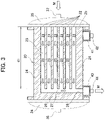
- FIG. 3 is a sectional view taken along line B-B in FIG. 1 .
- FIG. 4 is a three-dimensional cross-sectional view showing a part of the heat exchange section 2 according to the present embodiment.
- the reactor 1 heats or cools the reaction fluid by heat exchange between the reaction fluid containing the reaction raw material and the heat medium to promote the reaction of the reaction fluid.
- the reactor 1 includes a heat exchange section 2.
- the heat exchange section 2 includes a first heat conductor 10, a second heat conductor 20, and a lid plate 30.
- the first heat conductor 10, the second heat conductor 20, and the lid plate 30 are flat plate-like members formed of a heat-resistant and heat-conductive material, and have sufficient thicknesses to withstand a high internal pressure generated during the reaction fluid R flows.
- the first heat conductor 10 has a flow passage (hereinafter referred to as the first flow passage) 11 through which a reaction fluid flows.
- the second heat conductor 20 has a flow passage (Hereinafter referred to as the second flow passage) 21 through which the thermal medium flows.
- the first heat conductor 10 and the second heat conductor 20 are alternately stacked, and the lid plate 30 is installed on the uppermost one of them.
- the first flow passage 11 and the second flow passage 21 are adjacent to each other via the first partition wall 13 or the second partition wall 23 (see FIG. 4 ).
- the first flow passage 11 and the second flow passage 21 are adjacent to each other in a non-contact state in the stacking direction of the first heat conductor 10 and the second heat conductor 20.
- the heat exchange section 2 has a counterflow type structure in which a reaction fluid and a heat medium flow in opposite directions.
- a catalyst body 50 (see FIG. 5 ) as a packing is detachably installed in the first flow passage 11.
- a heat transfer enhancer (enhancement body) 55 (see FIG. 6 ) as a packing is detachably installed in the second flow passage 21.
- a jig 60 (see FIG. 7 ) for the reactor 1 is used for the installation and removal of these.
- the heat transfer enhancer 55 may not be installed in accordance with the specifications of the reactor 1.
- the heat exchange section 2 is constituted of at least one set of a first heat conductor 10 and a second heat conductor 20.
- the number of each heat conductor may be increased to improve the heat exchange performance.
- the number of flow passages formed in each heat conductor is set in consideration of the design conditions and heat transfer efficiency of the heat exchange section 2. Further, in order to suppress heat loss due to heat radiation from the heat exchange section 2, a housing or a heat insulating material may cover the periphery of the heat exchange section 2.
- Both ends of the heat exchange section 2 as a stacked body are held by fixing members 32 and 33.
- a reaction fluid introduction section 34 is attached to the fixing member 32.
- the reaction fluid introduction section 34 is a recessed curved lid body and forms a space S1 between the reaction fluid introduction section 34 and the heat exchange section 2.
- First inlet ports 12 of the first flow passages 11 are opened to the space S1 (see FIG. 2 ).
- the first inlet ports 12 are opened on the side surface (end surface) 2a of the heat exchange section 2 facing the reaction fluid introduction section 34.
- the reaction fluid introduction section 34 has a first introduction pipe 36 for introducing the reaction fluid R.
- the reaction fluid R flows into each of the first flow passages 11 through the first introduction pipe 36.
- the reaction fluid introduction section 34 is detachably or openably installed on the fixing member 32. With these attachment and detachment, for example, the operator can insert the catalyst body 50 into the first flow passage 11 or remove it from the first flow passage 11.
- the product discharge section 41 is a box-shaped member having one open surface.
- the product discharge section 41 is installed in the heat exchange section 2 so that the open surface is fitted to the first outlet port 18 of the first heat conductor 10.
- the product discharge section 41 has a first discharge pipe 42.
- the first exhaust pipe 42 discharges a reaction gas P containing a product derived from the reaction fluid R.
- a heat medium introduction section 35 is attached to the fixing member 33. Simillar to the reaction fluid introduction section 34, the heat medium introduction section 35 is a recessed curved lid body and forms a space S2 between the heat medium introduction section 35 and the heat exchange section 2. Second inlet ports 22 of the second flow passages 21 are opened into the space S2. In other words, the second inlet ports 22 are opened on the side surface (end surface) 2b of the heat exchange section 2 facing the heat medium introduction section 35.
- the heat medium introduction section 35 has a second introduction pipe 37 for introducing the heat medium M. The heat medium M flows into each second flow passage 21 through the second introduction pipe 37.
- the heat medium introduction section 35 is detachably or openably installed on the fixing member 33. With these attachment and detachment, for example, the operator can insert the heat transfer enhancer 55 into the second flow passage 21 or remove it from the second flow passage 21.
- the heat medium discharge section 43 is a box-shaped member having one open surface, similar to the product discharge section 41.
- the heat medium discharge section 43 is installed in the heat exchange section 2 so that the open surface is fitted to the second outlet port 28 of the second heat conductor 20.
- the heat medium discharge section 43 has a second discharge pipe 44.
- the second discharge pipe 44 discharges the heat medium M flowing through the heat exchange section 2.
- the first heat conductor 10 has first flow passages 11 including reaction regions.
- the intermediate portion of the first flow passage 11 is a main reaction region.
- the first flow passage 11 receives the heat of the heat medium flowing through the second flow passage 21 in the second heat conductor 20 described later and reacts the reaction fluid R to generate a reaction gas P containing a product derived from the reaction fluid R.
- the first flow passage 11 is a groove formed in one surface (upper surface in the present embodiment) of the first heat conductor 10.
- the groove has a rectangular cross section having a width w1 and a height h1 (see FIG. 4 ), and extends in one direction with a length d1 (see FIG. 2 ).
- the first flow passage 11 extends linearly toward the fixing member 32 from the first inlet port 12 located on the fixing member 33 side. As shown in FIG. 2 , the first flow passages 11 are arranged in parallel.
- the first heat conductor 10 includes a first partition wall 13, two first side walls 14, first intermediate walls 15, and a first end wall 16.
- the first side wall 14, the first intermediate wall 15 and the first end wall 16 are provided on one surface of the first partition wall 13.
- the first partition wall 13 is a rectangular wall portion and defines the overall shape of the first heat conductor 10.
- the first side walls 14 are wall portions provided on both sides of the extending direction of the first flow passages 11.
- the first intermediate walls 15 are wall parts positioned between the two first side walls 14 and provided in parallel with each of the first side walls 14.
- the first end wall 16 is a wall provided on the side opposite to the first inlet port 12 across the first flow passages 11, and extending in the arrangement direction of the first flow passages 11. The first end wall 16 prevents the reaction gas P from flowing into the space S2.
- the first heat conductor 10 has a first communication flow passage 17 extending along the first end wall 16.
- the first communication flow passage 17 communicates with all the first flow passages 11 and communicates with the first outlet port 18. Simillar to the first flow passages 11, the first communication flow passage 17 is a flow passage through which the reaction fluid R and the reaction gas P flow, and there is no substantial difference between them.
- the second heat conductor 20 has second flow passages 21.
- the second flow passages 21 supply the heat of the heat medium M to the first heat conductor 10.
- the second flow passage 21 is a groove formed in one surface (upper surface in the present embodiment) of the second heat conductor 20.
- the groove has a rectangular cross section having a width w1 and a height h1 (see FIG. 4 ), and extends in one direction with a length d1 (see FIG. 3 ).
- the second flow passage 21 extends linearly toward the fixing member 33 from the second inlet port 22 located on the fixing member 32 side. As shown in FIG. 3 , the second flow passages 21 are arranged in parallel. The width, height and length of the first flow passage 11 and the second flow passage 21 may be different.
- the second heat conductor 20 includes a second partition wall 23, two second side walls 24, second intermediate walls 25, and a second end wall 26.
- the second side wall 24, the second intermediate walls 25 and the second end wall 26 are provided on one surface of the second partition wall 23. That is, they are provided on the same surface as the surface on which the first side wall 14 and the like are provided with respect to the first partition wall 13.
- the second partition wall 23 is a rectangular wall that defines the overall shape of the second heat conductor 20.
- the second side wall 24 is a wall portion provided on both sides of the extending direction of the second flow passages 21.
- the second intermediate walls 25 are wall parts positioned between the two second side walls 24 and provided in parallel with the respective second side walls 24.
- the second end wall 26 is provided on the side opposite to the second inlet port 22 across the second flow passages 21, and is a wall portion extending in the arrangement direction of the second flow passages 21. The second end wall 26 prevents the heat medium M from flowing into the space S1.
- the second heat conductor 20 has a second communication flow passage 27 extending along the second end wall 26.
- the second communication flow passage 27 communicates with all the second flow passages 21 and communicates with the second outlet port 28.
- the heat exchanger 2 can be used as a liquid-to-liquid heat exchanger, a gas-to-air heat exchanger, or a gas-to-liquid heat exchanger.
- the reaction fluid and the heat medium may be either a gas or a liquid.
- the reactor 1 according to the present embodiment can perform chemical synthesis by various thermal reactions such as endothermic reaction, exothermic reaction or other reactions. Such thermal reactions are, for example, steam reforming reactions of methane represented by formula (1), endothermic reactions such as dry reforming reactions of methane represented by formula (2), shift reactions represented by formula (3), metanation reactions represented by formula (4), and exothermic reactions such as Fischer-Tropsch synthesis represented by formula (5).
- the reaction fluid in these reactions is a gas.
- the heat medium is preferably a material which does not corrode the constituent materials of the reactor 1.
- gaseous substances such as combustion gas, heating air or the like, can be used.
- the heat medium may be, for example, a liquid substance such as water, oil or the like.
- FIG. 5 is a perspective view showing an example of the catalyst body 50 according to the present embodiment.
- the catalyst body 50 is installed in the first flow passage 11 to promote the reaction in the reaction fluid.
- the catalyst body 50 has a base material 51 defining an overall shape and a catalyst layer 52 formed on (supported with) the surface of the base material 51.
- the base material 51 has a box-shaped outer shape of height h2, width w2, and depth d2 to be installed in the first flow passage 11.
- the base material 51 has a shape ensuring a large contact area with the reaction fluid. Therefore, the base material 51 is constituted of a corrugated plate forming the box-shaped outer shape, for example, as shown in FIG. 5 .
- the base material 51 is not limited to the corrugated plate, and may be a structure such as a porous body having a large number of through-passages formed along the reaction flow passage.
- the catalyst layer 52 contains an active metal as a main component, which is effective for promoting the progress of a chemical reaction.
- the active metal include Ni (nickel), Co (cobalt), Fe (iron), Pt (platinum), Ru (ruthenium), Rh (rhodium), Pd (palladium), and the like. One kind of them may be used. Otherwise, plural kinds of them may be used in combination as long as they are effective for promoting the reaction.
- the base material 51 is formed of a material having heat resistance and capable of supporting a catalyst.
- examples of such materials include heat-resistant alloys mainly composed of one or more kinds of metals such as Fe (iron), Cr (chromium), Al (aluminum), Y (yttrium), Co (cobalt), Ni (nickel), Mg (magnesium), Ti (titanium), Mo (molybdenum), W (tungsten), Nb (niobium) and Ta (tantalum).
- the catalyst body 50 may be formed by molding a thin plate-like structural material made of a heat-resistant alloy such as Fecralloy (registered trademark).
- FIG. 6 is a perspective view showing an example of the heat transfer enhancer 55 according to the present embodiment.
- the heat transfer enhancer 55 is installed in the second flow passage 21 to promote heat transfer between the heat medium and the second heat conductor 20.
- the heat transfer enhancer 55 has an outer shape of the same size as that of the catalyst body 50 to be installed in the second flow passage 21. That is, the heat transfer enhancer 55 has a box-shaped outer shape having a height h2, a width w2, and a depth d2.
- the heat transfer enhancer 55 has a shape for increasing the contact area between the heat medium and the second heat conductor 20. Therefore, as shown in FIG.
- the heat transfer enhancer 55 is constituted of a corrugated plate forming a box-shaped outer shape. Simillar to the base material 51 of the catalyst body 50, the heat transfer enhancer 55 is not limited to a corrugated plate, but may be a structure such as a porous body having a large number of through-passages formed along the heat medium flow passage.
- the heat transfer enhancer 55 is formed of a thermally conductive material such as aluminum, copper, stainless steel, iron plated steel, etc.
- FIG. 7(a) is a plan view of the jig 60 according to the present embodiment
- FIG. 7(b) is a side view of the jig 60 shown in FIG. 7(a)
- FIG. 8 is a view showing the insertion of the jig 60 into the flow passage and the subsequent state.
- the jig 60 is a tool for inserting the packing into the flow passage of the reactor 1 or for removing the packing from the flow passage.
- Flow passage refers to the first flow passage 11 or the second flow passage 21 as described above.
- packing refers to the catalyst body 50 or heat transfer enhancer 55 as described above.
- the jig 60 is designed for insertion and removal of the catalyst body 50. That is, the jig 60 in this example sandwiches (holds) the catalyst bodies 50 (see FIG. 8 ).
- a packing to be sandwiched is the heat transfer enhancer 55
- explanations relating to the catalyst body 50 may be replaced with and deemed as explanations relating to the heat transfer enhancer 55 in the following description.
- the catalyst body 50 may be replaced with the heat transfer enhancer 55
- the first flow passage 11 may be replaced with the second flow passage 21, in the following description.
- the jig 60 includes a pair of strip portions 61, 61 extending in parallel with each other, and link portions 62 arranged in the extending direction of the pair of strip portions 61, 61 and connecting the pair of strip portions 61, 61.
- the strip portions 61, 61 are flat plate-shaped members that are long, narrow, and thin.
- the strip portions 61, 61 are formed of a material excellent in toughness, heat resistance and corrosion resistance. Such a material is, for example, a superalloy such as a nickel-based alloy or the like.
- the first flow passage 11 is an elongated prismatic space having a length d1, a width w1, and a height h1.
- the jig 60 is installed in the first flow passage 11 together with the catalyst bodies 50. Accordingly, the jig 60 has an outer width w3 smaller than the width w1 and a height h3 lower than the height h1.
- the jig 60 has a length L longer than the length d1.
- the length L is set to 1 m, for example.
- the excess length of the length L with respect to the length d1 is arbitrary. For example, it is set within a range of several millimeters to several tens of millimeters in consideration of workability at the insertion time and the removal time.
- the strip portions 61, 61 are extended in one direction. This direction corresponds to the extending direction of the first flow passage 11.
- the strip portions 61, 61 have lengths greater than the first flow passages 11 (length d1) (see FIG. 8 ).
- the strip portions 61, 61 have widths defining the height h3 of the jig 60. That is, the widths of the strip portions 61, 61 are equal to the height h3 of the jig 60.
- the strip portions 61, 61 have thicknesses set to be less than half of the difference between the width w1 of the first flow passage 11 and the width w2 of the catalyst body 50.
- the link portion 62 is a rod-like member extending in a direction intersecting the extending direction of the pair of strip portions 61, 61.
- its dimension on the cross section of the jig 60 is set to a value sufficiently smaller than the height h3.
- the link portion 62 has a length with which a pair of strip portions 61, 61 sandwiches the catalyst body 50 between them. This length is equal to the inner width w4 (i.e., the distance between opposing surfaces of the pair of strip portions 61, 61) of the jig 60. Since each link portion 62 has the same length, the jig 60 has the appearance of a ladder.
- the link portion 62 is formed of the same material as the strip portions 61, 61.
- the pair of strip portions 61, 61 hold the catalyst body 50 between them.
- Each link portion 62 is dotted in the extending direction of the jig 60, and maintains the inner width v4 of the jig 60 within the allowable deflection range of the strip portions 61, 61. Accordingly, as shown in FIG. 8 , the jig 60 can sandwich (hold) the catalyst bodies 50 arranged in the stretching direction at once.
- the jig 60 While the catalyst bodies 50 are sandwiched at once, the jig 60 is inserted to a desired position in the first flow passage 11. In other words, it becomes easy to insert the catalyst bodies 50 into the first flow passage 11. Further, by this insertion, a part of the jig 60 is positioned in the first flow passage 11, and the catalyst bodies 50 are arranged at appropriate positions in the first flow passage. That is, it is possible to collectively install the catalyst bodies 50 at their appropriate positions with respect to one first flow passage 11. Further, it is possible to remove the catalyst bodies 50 from the first flow passage 11 at once by simply pulling out the jig 60 from the first flow passage 11.
- each strip portion 61 includes a tip end portion 61a provided as one end in the extending direction and a base end portion 61b provided as the other end in the extending direction.
- the tip end portions 61a may be inclined to approach the mating strip portions 61, 61. That is, the tip end of the jig 60 may have a tapered shape with the inclination of the tip end portions 61a.
- the jig 60 is inserted into the first flow passage 11 with the tip end portion 61a facing the first inlet port 12 of the first flow passage 11.
- the inclination of the tip end portions 61a suppresses excessive friction and unnecessary collision (abutting) between the jig 60 and the first flow passage 11, and assists insertion of the jig 60.
- the link portions 62 include first link portions 63 and at least one second link portion 64.
- the first link portions 63 are positioned on a side with the tip end portion 61a (base end side of the jig 60) of the strip portions 61, 61.
- the second link portion 64 is positioned closer to the base end portions 61b of the strip portions 61, 61 (the base end portion side of the jig 60) than the first link portion 63.
- the first link portion 63 may be provided with an interval d3 in the extending direction of the pair of strip portions 61, 61.
- the interval d3 is slightly longer than the depth d2 of the catalyst body 50.
- the pair of strip portions 61, 61 and the first link portions 63 form a frame 65 opening in a direction orthogonal to a plane on which the pair of strip portions 61, 61 extend.
- the frame 65 is located in the XY plane and opens in the Z direction.
- the opening area of the frame 65 is larger than the cross-sectional area of the catalyst body 50 facing the frame 65.
- the catalyst body 50 is positioned within the frame 65 and sandwiched by the pair of strip portions 61, 61. Accordingly, when the catalyst bodies 50 are inserted, the catalyst bodies 50 move in the first flow passage 11 while being pushed by the first link portions 63. On the other hand, the catalyst bodies 50 cannot deviate from the frames 65 in the X and Y directions. Therefore, it is possible to easily and accurately position the catalyst bodies 50 at ones. When the catalyst bodies 50 are removed, they abut on the first link portions 63. Thus, all catalyst bodies 50 can be reliably and collectively removed.
- the opening area of the frame 65 is larger than the cross-sectional area of the catalyst body 50 facing the frame 65. That is, the jig 60 according to the present embodiment does not have a structure, which interferes with the flow of heat between the heat medium and the catalyst body 50, between the second partition wall 23 (see FIG. 3 ) and the catalyst body 50. Therefore, it is possible to suppress the increase of the thermal resistance between the heat medium and the catalyst body 50 due to such structure holding the catalyst body 50.
- the first link portion 63 may be connected to the center in the width direction of each strip portion 61, 61. Thereby, the first link portion 63 surely abuts on the catalyst body 50. Therefore, the positional deviation caused by the reaction fluid can be kept in the frame 65 and the deviation from the first flow passage 11 can be prevented. Further, the catalyst body 50 can be reliably moved during insertion and removal.
- the second link portion 64 may be connected to a position shifted from the center in the width direction of each strip portion 61, 61.
- the second link portion 64 may be connected to an end portion (edge portion) in the width direction of each strip portion 61, 61.
- At least one of the second link portions 64 may be located at a portion exposed from the first flow passage 11 in the pair of strip portions 61, 61. That is, as shown in FIG. 8 , while the jig 60 is inserted together with the catalyst body 50 to a desired position in the first flow passage 11, at least one of the second link portions 64 may be exposed to the outside from the first flow passage 11 (heat exchange section 2).
- the second link portion 64 exposed to the outside forms a handle portion gripped by a tool (not shown) or a hook portion to be hooked together with the pair of strip portions 61, 61.
- FIGs. 9(a) to 9(f) are views illustrating exemplary embodiments of link portion 62 (first link portion 63 and second link portion 64).
- the link portion 62 may be composed of two band-shaped members (bar-shaped members) 66, 66.
- each band-shaped member 66 has a main part 66a extending between the pair of strip portions 61, 61, and a base portion 66b provided at both ends of the main part 66a and extending at right angles and in one direction to the main part 66a.
- One band-shaped member 66 is arranged with the tips of the main parts 66a, 66a directed to one side in the extending direction of the first flow passage 11, and the other band-shaped member 66 is arranged with the tips of the main parts 66a, 66a directed to the other side in the extending direction of the first flow passage 11.
- the main parts 66a, 66a are in close contact with each other.
- the base portion 66b of each band-shaped member 66 is fixed to corresponding strip portions 61, 61 by welding or the like. As shown in FIG. 9(b) , the band-shaped members 66, 66 may be fixed in a state where the base portion 66b is disposed perpendicular to the extending direction of the first flow passage 11.
- the link portion 62 may be formed of a rod-like member such as a round bar.
- each end of the rod-like member is fitted into the groove portion 61c formed in each strip portion 61, 61 by press-fitting or the like.
- each end portion of the rod-shaped member may be fixed to each strip portion 61, 61 by welding.
- the link portion 62 may be constituted by two branch portions 61d, 61d respectively branched from a pair of the strip portions 61, 61.
- the two branch portions 61d, 61d are welded and integrated to be overlapped on each other.
- the branch portion 61d may be provided on only one of the pair of strip portions 61, 61. In this case, the tip of the branch portion 61d branched from one strip portion is fixed to the other strip portion having no branch portion 61d by welding or the like.
Abstract

Description
- The present disclosure relates to a jig for inserting or removing a packing such as a catalyst body installed in a flow passage of a reactor.
- Heat exchange type reactors heat or cool a reaction fluid containing a reaction raw material by heat medium to promote the reaction of the reaction fluid. Such a reactor includes, for example, a heat exchange section having reaction flow passages for flowing a reaction fluid and heat medium passages for flowing a heat medium. A catalyst body may be provided in the reaction flow passage to promote the reaction. Methods of installing the catalyst body include: methods of directly providing such as filling powder or pellets into the reaction flow passage, or supporing the catalyst on wall surfaces; and a method of inserting structured catalysts into the reaction flow passage.
- When a cross-sectional area of the reaction flow passage is reduced while the volume of the reaction field is kept constant, the contact area (specific surface area) between the reaction fluid and the catalyst per unit volume is improved. In this case, accordingly, the heat transfer efficiency can be increased, and the reaction rate and yield can be improved. Patent Literature 1 discloses a reactor which is intended to simplify the replacement operation of a catalyst body in a flow channel while reducing the cross section of the flow channel.
- Patent Literature 1:
JP 2007-237044 A - In a reactor in which a catalyst body is installed in a reaction flow passage, the catalyst body is likely to be firmly sticked on the inner surface of the reaction flow passage by a long time operation. In particular, when the catalytic reaction proceeds at a high temperature or is accompanied by heat generation, the adhesion of the catalyst body is promoted by interdiffusion of materials of the reaction flow passage and the catalyst. When the catalyst body is firmly sticked to the reaction flow passage, removal of the catalyst body becomes difficult. In particular, in a reactor called a compact reactor or a microreactor, the contact area of the inner surface of the reaction flow passage with respect to the size of the catalyst body is relatively large because the cross-sectional area of the reaction flow passage is in the range of several to several tens of mm2. Therefore, in such a reactor, it becomes more difficult to remove the fixed catalyst body. Further, in such an apparatus, the number of reaction flow passages reaches from several hundred to several thousand, so that it is necessary to smoothly insert the catalyst into the reaction flow passages.
- It is therefore an object of the present disclosure to provide a jig that facilitates insertion and removal of a packing such as a catalyst body disposed in a flow passage of a reactor.
- One aspect of the present disclosure is a jig for inserting a packing into a flow passage of a reactor extending in one direction or for removing the packing from the flow passage. The jig includes: a pair of strip portions extending in parallel with each other, having a length longer than the flow passage; and link portions arranged in an extending direction of the pair of strip portions, linking the pair of strip portions and having lengths with which the pair of strip portions sandwich the packing between the pair of strip portions.
- Each of the strip portions may include: a tip end portion provided as one end in the extending direction; and a base end portion provided as the other end in the extending direction. The tip end portion of one of the pair of strip portions may be inclined to approach the strip portion of the other of the pair of strip portions. The link portions may include: first link portions positioned on a side with the tip end porion and provided at intervals longer than the packing in the extending direction of the pair of strip portions; and at least one second link portion positioned closer to the base end portion than the first link portions. Each of the first link portions may be connected to a center of each strip portion in a width direction thereof. Each second link portion may be connected to a position shifted from a center of each strip portion in a width direction thereof. At least one of the at least one second link portion may be located at a part of the pair of strips, the portion being exposed from the flow passage. The flow passage may be a reaction flow passage throung which a reaction fluid flows, and the packing may be a catalyst body.
- According to the present disclosure, it is possible to provide a jig which facilitates insertion and removal of a packing such as a catalyst body installed in a flow passage of a reactor.
-
-
FIG. 1 is a side view showing a reactor according to an embodiment. -
FIG. 2 is a cross-sectional view taken along line A-A ofFIG. 1 . -
FIG. 3 is a cross-sectional view taken along line B-B ofFIG. 1 . -
FIG. 4 is a three-dimensional cross-sectional view showing a part of a heat exchange section according to an embodiment. -
FIG. 5 is a perspective view showing an example of a catalyst body according to an embodiment. -
FIG. 6 is a perspective view showing an example of a heat transfer enhancer according to an embodiment. -
FIG. 7 (a) is a plan view of a jig according to an embodiment, andFIG. 7(b) is a side view of the jig shown inFIG. 7(a) . -
FIG. 8 is a view showing the insertion of the jig into a flow passage and the subsequent state. -
FIGs. 9(a) to 9(f) are views illustrating exemplary embodiments of a link portion. - Embodiments of the present disclosure will be described below with reference to the drawings. Note that the same reference numerals are given to the common parts in each of the figures, and duplicated explanations are omitted.
-
FIG. 1 is a side view showing a reactor (catalytic reactor) 1 according to the present embodiment.FIG. 2 is a cross-sectional view taken along line A-A inFIG. 1 .FIG. 3 is a sectional view taken along line B-B inFIG. 1 .FIG. 4 is a three-dimensional cross-sectional view showing a part of theheat exchange section 2 according to the present embodiment. - The reactor 1 heats or cools the reaction fluid by heat exchange between the reaction fluid containing the reaction raw material and the heat medium to promote the reaction of the reaction fluid. The reactor 1 includes a
heat exchange section 2. Theheat exchange section 2 includes afirst heat conductor 10, asecond heat conductor 20, and alid plate 30. Thefirst heat conductor 10, thesecond heat conductor 20, and thelid plate 30 are flat plate-like members formed of a heat-resistant and heat-conductive material, and have sufficient thicknesses to withstand a high internal pressure generated during the reaction fluid R flows. - The
first heat conductor 10 has a flow passage (hereinafter referred to as the first flow passage) 11 through which a reaction fluid flows. On the other hand, thesecond heat conductor 20 has a flow passage (Hereinafter referred to as the second flow passage) 21 through which the thermal medium flows. Thefirst heat conductor 10 and thesecond heat conductor 20 are alternately stacked, and thelid plate 30 is installed on the uppermost one of them. - With the above-described stacking, the
first flow passage 11 and thesecond flow passage 21 are adjacent to each other via thefirst partition wall 13 or the second partition wall 23 (seeFIG. 4 ). In other words, thefirst flow passage 11 and thesecond flow passage 21 are adjacent to each other in a non-contact state in the stacking direction of thefirst heat conductor 10 and thesecond heat conductor 20. - The
heat exchange section 2 has a counterflow type structure in which a reaction fluid and a heat medium flow in opposite directions. A catalyst body 50 (seeFIG. 5 ) as a packing is detachably installed in thefirst flow passage 11. Similarly, a heat transfer enhancer (enhancement body) 55 (seeFIG. 6 ) as a packing is detachably installed in thesecond flow passage 21. Further, a jig 60 (seeFIG. 7 ) for the reactor 1 is used for the installation and removal of these. Theheat transfer enhancer 55 may not be installed in accordance with the specifications of the reactor 1. - The
heat exchange section 2 is constituted of at least one set of afirst heat conductor 10 and asecond heat conductor 20. The number of each heat conductor may be increased to improve the heat exchange performance. The number of flow passages formed in each heat conductor is set in consideration of the design conditions and heat transfer efficiency of theheat exchange section 2. Further, in order to suppress heat loss due to heat radiation from theheat exchange section 2, a housing or a heat insulating material may cover the periphery of theheat exchange section 2. - Both ends of the
heat exchange section 2 as a stacked body are held by fixingmembers fluid introduction section 34 is attached to the fixingmember 32. The reactionfluid introduction section 34 is a recessed curved lid body and forms a space S1 between the reactionfluid introduction section 34 and theheat exchange section 2.First inlet ports 12 of thefirst flow passages 11 are opened to the space S1 (seeFIG. 2 ). In other words, thefirst inlet ports 12 are opened on the side surface (end surface) 2a of theheat exchange section 2 facing the reactionfluid introduction section 34. The reactionfluid introduction section 34 has afirst introduction pipe 36 for introducing the reaction fluid R. The reaction fluid R flows into each of thefirst flow passages 11 through thefirst introduction pipe 36. - The reaction
fluid introduction section 34 is detachably or openably installed on the fixingmember 32. With these attachment and detachment, for example, the operator can insert thecatalyst body 50 into thefirst flow passage 11 or remove it from thefirst flow passage 11. - The
product discharge section 41 is a box-shaped member having one open surface. Theproduct discharge section 41 is installed in theheat exchange section 2 so that the open surface is fitted to thefirst outlet port 18 of thefirst heat conductor 10. Theproduct discharge section 41 has afirst discharge pipe 42. Thefirst exhaust pipe 42 discharges a reaction gas P containing a product derived from the reaction fluid R. - A heat
medium introduction section 35 is attached to the fixingmember 33. Simillar to the reactionfluid introduction section 34, the heatmedium introduction section 35 is a recessed curved lid body and forms a space S2 between the heatmedium introduction section 35 and theheat exchange section 2.Second inlet ports 22 of thesecond flow passages 21 are opened into the space S2. In other words, thesecond inlet ports 22 are opened on the side surface (end surface) 2b of theheat exchange section 2 facing the heatmedium introduction section 35. The heatmedium introduction section 35 has asecond introduction pipe 37 for introducing the heat medium M. The heat medium M flows into eachsecond flow passage 21 through thesecond introduction pipe 37. - The heat
medium introduction section 35 is detachably or openably installed on the fixingmember 33. With these attachment and detachment, for example, the operator can insert theheat transfer enhancer 55 into thesecond flow passage 21 or remove it from thesecond flow passage 21. - The heat
medium discharge section 43 is a box-shaped member having one open surface, similar to theproduct discharge section 41. The heatmedium discharge section 43 is installed in theheat exchange section 2 so that the open surface is fitted to thesecond outlet port 28 of thesecond heat conductor 20. The heatmedium discharge section 43 has asecond discharge pipe 44. Thesecond discharge pipe 44 discharges the heat medium M flowing through theheat exchange section 2. - As shown in
FIG. 2 , thefirst heat conductor 10 hasfirst flow passages 11 including reaction regions. The intermediate portion of thefirst flow passage 11 is a main reaction region. Thefirst flow passage 11 receives the heat of the heat medium flowing through thesecond flow passage 21 in thesecond heat conductor 20 described later and reacts the reaction fluid R to generate a reaction gas P containing a product derived from the reaction fluid R. - The
first flow passage 11 is a groove formed in one surface (upper surface in the present embodiment) of thefirst heat conductor 10. The groove has a rectangular cross section having a width w1 and a height h1 (seeFIG. 4 ), and extends in one direction with a length d1 (seeFIG. 2 ). Thefirst flow passage 11 extends linearly toward the fixingmember 32 from thefirst inlet port 12 located on the fixingmember 33 side. As shown inFIG. 2 , thefirst flow passages 11 are arranged in parallel. - The
first heat conductor 10 includes afirst partition wall 13, twofirst side walls 14, firstintermediate walls 15, and afirst end wall 16. Thefirst side wall 14, the firstintermediate wall 15 and thefirst end wall 16 are provided on one surface of thefirst partition wall 13. Thefirst partition wall 13 is a rectangular wall portion and defines the overall shape of thefirst heat conductor 10. Thefirst side walls 14 are wall portions provided on both sides of the extending direction of thefirst flow passages 11. The firstintermediate walls 15 are wall parts positioned between the twofirst side walls 14 and provided in parallel with each of thefirst side walls 14. - The
first end wall 16 is a wall provided on the side opposite to thefirst inlet port 12 across thefirst flow passages 11, and extending in the arrangement direction of thefirst flow passages 11. Thefirst end wall 16 prevents the reaction gas P from flowing into the space S2. - The
first heat conductor 10 has a firstcommunication flow passage 17 extending along thefirst end wall 16. The firstcommunication flow passage 17 communicates with all thefirst flow passages 11 and communicates with thefirst outlet port 18. Simillar to thefirst flow passages 11, the firstcommunication flow passage 17 is a flow passage through which the reaction fluid R and the reaction gas P flow, and there is no substantial difference between them. - As shown in
FIG. 3 , thesecond heat conductor 20 hassecond flow passages 21. Thesecond flow passages 21 supply the heat of the heat medium M to thefirst heat conductor 10. - The
second flow passage 21 is a groove formed in one surface (upper surface in the present embodiment) of thesecond heat conductor 20. The groove has a rectangular cross section having a width w1 and a height h1 (seeFIG. 4 ), and extends in one direction with a length d1 (seeFIG. 3 ). Thesecond flow passage 21 extends linearly toward the fixingmember 33 from thesecond inlet port 22 located on the fixingmember 32 side. As shown inFIG. 3 , thesecond flow passages 21 are arranged in parallel. The width, height and length of thefirst flow passage 11 and thesecond flow passage 21 may be different. - The
second heat conductor 20 includes asecond partition wall 23, twosecond side walls 24, secondintermediate walls 25, and asecond end wall 26. Thesecond side wall 24, the secondintermediate walls 25 and thesecond end wall 26 are provided on one surface of thesecond partition wall 23. That is, they are provided on the same surface as the surface on which thefirst side wall 14 and the like are provided with respect to thefirst partition wall 13. Thesecond partition wall 23 is a rectangular wall that defines the overall shape of thesecond heat conductor 20. Thesecond side wall 24 is a wall portion provided on both sides of the extending direction of thesecond flow passages 21. The secondintermediate walls 25 are wall parts positioned between the twosecond side walls 24 and provided in parallel with the respectivesecond side walls 24. - The
second end wall 26 is provided on the side opposite to thesecond inlet port 22 across thesecond flow passages 21, and is a wall portion extending in the arrangement direction of thesecond flow passages 21. Thesecond end wall 26 prevents the heat medium M from flowing into the space S1. - The
second heat conductor 20 has a second communication flow passage 27 extending along thesecond end wall 26. The second communication flow passage 27 communicates with all thesecond flow passages 21 and communicates with thesecond outlet port 28. - The
heat exchanger 2 can be used as a liquid-to-liquid heat exchanger, a gas-to-air heat exchanger, or a gas-to-liquid heat exchanger. The reaction fluid and the heat medium may be either a gas or a liquid. The reactor 1 according to the present embodiment can perform chemical synthesis by various thermal reactions such as endothermic reaction, exothermic reaction or other reactions. Such thermal reactions are, for example, steam reforming reactions of methane represented by formula (1), endothermic reactions such as dry reforming reactions of methane represented by formula (2), shift reactions represented by formula (3), metanation reactions represented by formula (4), and exothermic reactions such as Fischer-Tropsch synthesis represented by formula (5). Here, the reaction fluid in these reactions is a gas.
CH4 + H2O → 3H2 + CO · · · (1)
CH4 + CO2 → 2H2 + 2CO · · · (2)
CO + H2O → CO2 + H2 · · · (3)
CO + 3H2 → CH4 + H2O · · · (4)
(2n + 1) H2 + nCO → CnH2n + 2 + nH2O · · · (5)
- The heat medium is preferably a material which does not corrode the constituent materials of the reactor 1. When heating gas is used as the heat medium, gaseous substances such as combustion gas, heating air or the like, can be used. The heat medium may be, for example, a liquid substance such as water, oil or the like.
-
FIG. 5 is a perspective view showing an example of thecatalyst body 50 according to the present embodiment. Thecatalyst body 50 is installed in thefirst flow passage 11 to promote the reaction in the reaction fluid. As shown inFIG. 5 , thecatalyst body 50 has abase material 51 defining an overall shape and acatalyst layer 52 formed on (supported with) the surface of thebase material 51. Thebase material 51 has a box-shaped outer shape of height h2, width w2, and depth d2 to be installed in thefirst flow passage 11. Thebase material 51 has a shape ensuring a large contact area with the reaction fluid. Therefore, thebase material 51 is constituted of a corrugated plate forming the box-shaped outer shape, for example, as shown inFIG. 5 . Note that thebase material 51 is not limited to the corrugated plate, and may be a structure such as a porous body having a large number of through-passages formed along the reaction flow passage. - The
catalyst layer 52 contains an active metal as a main component, which is effective for promoting the progress of a chemical reaction. Examples of the active metal include Ni (nickel), Co (cobalt), Fe (iron), Pt (platinum), Ru (ruthenium), Rh (rhodium), Pd (palladium), and the like. One kind of them may be used. Otherwise, plural kinds of them may be used in combination as long as they are effective for promoting the reaction. - The
base material 51 is formed of a material having heat resistance and capable of supporting a catalyst. Examples of such materials include heat-resistant alloys mainly composed of one or more kinds of metals such as Fe (iron), Cr (chromium), Al (aluminum), Y (yttrium), Co (cobalt), Ni (nickel), Mg (magnesium), Ti (titanium), Mo (molybdenum), W (tungsten), Nb (niobium) and Ta (tantalum). For example, thecatalyst body 50 may be formed by molding a thin plate-like structural material made of a heat-resistant alloy such as Fecralloy (registered trademark). -
FIG. 6 is a perspective view showing an example of theheat transfer enhancer 55 according to the present embodiment. Theheat transfer enhancer 55 is installed in thesecond flow passage 21 to promote heat transfer between the heat medium and thesecond heat conductor 20. As shown inFIG. 6 , theheat transfer enhancer 55 has an outer shape of the same size as that of thecatalyst body 50 to be installed in thesecond flow passage 21. That is, theheat transfer enhancer 55 has a box-shaped outer shape having a height h2, a width w2, and a depth d2. Theheat transfer enhancer 55 has a shape for increasing the contact area between the heat medium and thesecond heat conductor 20. Therefore, as shown inFIG. 6 , for example, theheat transfer enhancer 55 is constituted of a corrugated plate forming a box-shaped outer shape. Simillar to thebase material 51 of thecatalyst body 50, theheat transfer enhancer 55 is not limited to a corrugated plate, but may be a structure such as a porous body having a large number of through-passages formed along the heat medium flow passage. Theheat transfer enhancer 55 is formed of a thermally conductive material such as aluminum, copper, stainless steel, iron plated steel, etc. - Next, the
jig 60 will be described. -
FIG. 7(a) is a plan view of thejig 60 according to the present embodiment, andFIG. 7(b) is a side view of thejig 60 shown inFIG. 7(a) .FIG. 8 is a view showing the insertion of thejig 60 into the flow passage and the subsequent state. Thejig 60 is a tool for inserting the packing into the flow passage of the reactor 1 or for removing the packing from the flow passage. Flow passage refers to thefirst flow passage 11 or thesecond flow passage 21 as described above. Also, packing refers to thecatalyst body 50 orheat transfer enhancer 55 as described above. - Hereinafter, a description will be given of an example in which the
jig 60 is designed for insertion and removal of thecatalyst body 50. That is, thejig 60 in this example sandwiches (holds) the catalyst bodies 50 (seeFIG. 8 ). However, in the case where a packing to be sandwiched is theheat transfer enhancer 55, explanations relating to thecatalyst body 50 may be replaced with and deemed as explanations relating to theheat transfer enhancer 55 in the following description. For example, thecatalyst body 50 may be replaced with theheat transfer enhancer 55, and thefirst flow passage 11 may be replaced with thesecond flow passage 21, in the following description. - As shown in
FIG. 7 , thejig 60 includes a pair ofstrip portions portions 62 arranged in the extending direction of the pair ofstrip portions strip portions strip portions strip portions - As shown in
FIGs. 2 and4 , thefirst flow passage 11 is an elongated prismatic space having a length d1, a width w1, and a height h1. As shown inFIG. 8 , thejig 60 is installed in thefirst flow passage 11 together with thecatalyst bodies 50. Accordingly, thejig 60 has an outer width w3 smaller than the width w1 and a height h3 lower than the height h1. However, thejig 60 has a length L longer than the length d1. The length L is set to 1 m, for example. The excess length of the length L with respect to the length d1 is arbitrary. For example, it is set within a range of several millimeters to several tens of millimeters in consideration of workability at the insertion time and the removal time. - The
strip portions first flow passage 11. Thestrip portions FIG. 8 ). Thestrip portions jig 60. That is, the widths of thestrip portions jig 60. Thestrip portions first flow passage 11 and the width w2 of thecatalyst body 50. - The
link portion 62 is a rod-like member extending in a direction intersecting the extending direction of the pair ofstrip portions link portion 62 from interfering with the flow of the reaction fluid, its dimension on the cross section of thejig 60 is set to a value sufficiently smaller than the height h3. Thelink portion 62 has a length with which a pair ofstrip portions catalyst body 50 between them. This length is equal to the inner width w4 (i.e., the distance between opposing surfaces of the pair ofstrip portions 61, 61) of thejig 60. Since eachlink portion 62 has the same length, thejig 60 has the appearance of a ladder. Thelink portion 62 is formed of the same material as thestrip portions - The pair of
strip portions catalyst body 50 between them. Eachlink portion 62 is dotted in the extending direction of thejig 60, and maintains the inner width v4 of thejig 60 within the allowable deflection range of thestrip portions FIG. 8 , thejig 60 can sandwich (hold) thecatalyst bodies 50 arranged in the stretching direction at once. - While the
catalyst bodies 50 are sandwiched at once, thejig 60 is inserted to a desired position in thefirst flow passage 11. In other words, it becomes easy to insert thecatalyst bodies 50 into thefirst flow passage 11. Further, by this insertion, a part of thejig 60 is positioned in thefirst flow passage 11, and thecatalyst bodies 50 are arranged at appropriate positions in the first flow passage. That is, it is possible to collectively install thecatalyst bodies 50 at their appropriate positions with respect to onefirst flow passage 11. Further, it is possible to remove thecatalyst bodies 50 from thefirst flow passage 11 at once by simply pulling out thejig 60 from thefirst flow passage 11. - As shown in
FIG. 7(a) , eachstrip portion 61 includes atip end portion 61a provided as one end in the extending direction and abase end portion 61b provided as the other end in the extending direction. Thetip end portions 61a may be inclined to approach themating strip portions jig 60 may have a tapered shape with the inclination of thetip end portions 61a. As shown inFIG. 8 , thejig 60 is inserted into thefirst flow passage 11 with thetip end portion 61a facing thefirst inlet port 12 of thefirst flow passage 11. The inclination of thetip end portions 61a suppresses excessive friction and unnecessary collision (abutting) between thejig 60 and thefirst flow passage 11, and assists insertion of thejig 60. - As shown in
FIG. 7(a) , thelink portions 62 includefirst link portions 63 and at least onesecond link portion 64. Thefirst link portions 63 are positioned on a side with thetip end portion 61a (base end side of the jig 60) of thestrip portions second link portion 64 is positioned closer to thebase end portions 61b of thestrip portions 61, 61 (the base end portion side of the jig 60) than thefirst link portion 63. - The
first link portion 63 may be provided with an interval d3 in the extending direction of the pair ofstrip portions catalyst body 50. In this case, the pair ofstrip portions first link portions 63 form aframe 65 opening in a direction orthogonal to a plane on which the pair ofstrip portions first heat conductor 10 and thesecond heat conductor 20 is defined as the Z direction (seeFIGs. 4 and7 ), theframe 65 is located in the XY plane and opens in the Z direction. - The opening area of the
frame 65 is larger than the cross-sectional area of thecatalyst body 50 facing theframe 65. In other words, thecatalyst body 50 is positioned within theframe 65 and sandwiched by the pair ofstrip portions catalyst bodies 50 are inserted, thecatalyst bodies 50 move in thefirst flow passage 11 while being pushed by thefirst link portions 63. On the other hand, thecatalyst bodies 50 cannot deviate from theframes 65 in the X and Y directions. Therefore, it is possible to easily and accurately position thecatalyst bodies 50 at ones. When thecatalyst bodies 50 are removed, they abut on thefirst link portions 63. Thus, allcatalyst bodies 50 can be reliably and collectively removed. - As described above, the opening area of the
frame 65 is larger than the cross-sectional area of thecatalyst body 50 facing theframe 65. That is, thejig 60 according to the present embodiment does not have a structure, which interferes with the flow of heat between the heat medium and thecatalyst body 50, between the second partition wall 23 (seeFIG. 3 ) and thecatalyst body 50. Therefore, it is possible to suppress the increase of the thermal resistance between the heat medium and thecatalyst body 50 due to such structure holding thecatalyst body 50. - The
first link portion 63 may be connected to the center in the width direction of eachstrip portion first link portion 63 surely abuts on thecatalyst body 50. Therefore, the positional deviation caused by the reaction fluid can be kept in theframe 65 and the deviation from thefirst flow passage 11 can be prevented. Further, thecatalyst body 50 can be reliably moved during insertion and removal. - The
second link portion 64 may be connected to a position shifted from the center in the width direction of eachstrip portion FIG. 7(b) , thesecond link portion 64 may be connected to an end portion (edge portion) in the width direction of eachstrip portion strip portions second link portion 64 can be reduced. - At least one of the
second link portions 64 may be located at a portion exposed from thefirst flow passage 11 in the pair ofstrip portions FIG. 8 , while thejig 60 is inserted together with thecatalyst body 50 to a desired position in thefirst flow passage 11, at least one of thesecond link portions 64 may be exposed to the outside from the first flow passage 11 (heat exchange section 2). Thesecond link portion 64 exposed to the outside forms a handle portion gripped by a tool (not shown) or a hook portion to be hooked together with the pair ofstrip portions jig 60 from thefirst flow passage 11, thecatalyst body 50 can be efficiently removed. Especially, this effect becomes remarkable when the number of thefirst flow passages 11 increases. -
FIGs. 9(a) to 9(f) are views illustrating exemplary embodiments of link portion 62 (first link portion 63 and second link portion 64). As shown inFIG. 9(a) , thelink portion 62 may be composed of two band-shaped members (bar-shaped members) 66, 66. In this case, each band-shapedmember 66 has amain part 66a extending between the pair ofstrip portions base portion 66b provided at both ends of themain part 66a and extending at right angles and in one direction to themain part 66a. - One band-shaped
member 66 is arranged with the tips of themain parts first flow passage 11, and the other band-shapedmember 66 is arranged with the tips of themain parts first flow passage 11. Themain parts base portion 66b of each band-shapedmember 66 is fixed to correspondingstrip portions FIG. 9(b) , the band-shapedmembers base portion 66b is disposed perpendicular to the extending direction of thefirst flow passage 11. - As shown in
FIG. 9(c) , thelink portion 62 may be formed of a rod-like member such as a round bar. In this case, each end of the rod-like member is fitted into thegroove portion 61c formed in eachstrip portion FIG. 9(d) , each end portion of the rod-shaped member may be fixed to eachstrip portion - As shown in
FIG. 9(e) , thelink portion 62 may be constituted by twobranch portions strip portions branch portions FIG. 9(f) , thebranch portion 61d may be provided on only one of the pair ofstrip portions branch portion 61d branched from one strip portion is fixed to the other strip portion having nobranch portion 61d by welding or the like. - It should be noted that the present disclosure is not limited to the embodiments described above, but is indicated by the claims, and further includes all modifications within and meaning equivalent to the scope of claims.
Claims (7)
- A jig for inserting a packing into a flow passage of a reactor extending in one direction or for removing the packing from the flow passage, comprising:a pair of strip portions extending in parallel with each other, having a length longer than the flow passage; andlink portions arranged in an extending direction of the pair of strip portions, linking the pair of strip portions and having lengths with which the pair of strip portions sandwich the packing between the pair of strip portions.
- The jig according to claim 1, whereineach of the strip portions includes:a tip end portion provided as one end in the extending direction; anda base end portion provided as the other end in the extending direction, andthe tip end portion of one of the pair of strip portions is inclined to approach the strip portion of the other of the pair of strip portions.
- The jig according to claim 1 or 2, wherein
the link portions include:first link portions positioned on a side with the tip end porion and provided at intervals longer than the packing in the extending direction of the pair of strip portions; andat least one second link portion positioned closer to the base end portion than the first link portions. - The jig according to claim 3, wherein
each of the first link portions is connected to a center of each strip portion in a width direction thereof. - The jig according to claim 3, wherein
each second link portion is connected to a position shifted from a center of each strip portion in a width direction thereof. - The jig according to any one of claims 3 to 5, wherein
at least one of the at least one second link portion is located at a part of the pair of strips, the portion being exposed from the flow passage. - The jig according to any one of claims 1 to 6, whereinthe flow passage is a reaction flow passage throung which a reaction fluid flows, andthe packing is a catalyst body.
Applications Claiming Priority (1)
| Application Number | Priority Date | Filing Date | Title |
|---|---|---|---|
| PCT/JP2019/044504 WO2021095157A1 (en) | 2019-11-13 | 2019-11-13 | Jig for inserting filling member into reactor |
Publications (2)
| Publication Number | Publication Date |
|---|---|
| EP4059600A1 true EP4059600A1 (en) | 2022-09-21 |
| EP4059600A4 EP4059600A4 (en) | 2023-07-19 |
Family
ID=75911932
Family Applications (1)
| Application Number | Title | Priority Date | Filing Date |
|---|---|---|---|
| EP19952553.6A Pending EP4059600A4 (en) | 2019-11-13 | 2019-11-13 | Jig for inserting filling member into reactor |
Country Status (5)
| Country | Link |
|---|---|
| US (1) | US20220176339A1 (en) |
| EP (1) | EP4059600A4 (en) |
| CN (1) | CN114390946A (en) |
| CA (1) | CA3151305A1 (en) |
| WO (1) | WO2021095157A1 (en) |
Family Cites Families (11)
| Publication number | Priority date | Publication date | Assignee | Title |
|---|---|---|---|---|
| US3927984A (en) * | 1973-12-07 | 1975-12-23 | Gen Motors Corp | Catalytic converter bed support means |
| JPH0615404Y2 (en) * | 1986-12-19 | 1994-04-20 | 三菱電機株式会社 | Internal reforming fuel cell |
| JP2007237044A (en) | 2006-03-07 | 2007-09-20 | Kobe Steel Ltd | Microreactor and method for producing hydrogen by using the same |
| GB201110913D0 (en) * | 2011-06-28 | 2011-08-10 | Compactgtl Plc | Insertion of inserts into channels of a catalytic reactor |
| JP2014161777A (en) * | 2013-02-22 | 2014-09-08 | Sumitomo Precision Prod Co Ltd | Catalytic reactor and method for manufacturing a catalytic reactor |
| WO2014208444A1 (en) * | 2013-06-26 | 2014-12-31 | 株式会社Ihi | Catalyst structure, reactor, and manufacturing method for catalyst structure |
| JP2015157245A (en) * | 2014-02-21 | 2015-09-03 | 三菱日立パワーシステムズ株式会社 | Jig for extraction/insertion operation of plate-shaped catalyst and operation method using the same |
| JP6728739B2 (en) * | 2016-02-12 | 2020-07-22 | 株式会社Ihi | Reactor |
| JP6728781B2 (en) * | 2016-03-03 | 2020-07-22 | 株式会社Ihi | Reactor |
| CN106317098A (en) * | 2016-07-27 | 2017-01-11 | 嘉兴学院 | Method for preparing methyl dichlorosilane through catalytic hydrogenation of methyl trichlorosilane |
| JP6939022B2 (en) * | 2017-03-31 | 2021-09-22 | 株式会社Ihi | Catalytic reactor |
-
2019
- 2019-11-13 CN CN201980100389.8A patent/CN114390946A/en active Pending
- 2019-11-13 WO PCT/JP2019/044504 patent/WO2021095157A1/en unknown
- 2019-11-13 CA CA3151305A patent/CA3151305A1/en active Pending
- 2019-11-13 EP EP19952553.6A patent/EP4059600A4/en active Pending
-
2022
- 2022-02-28 US US17/681,888 patent/US20220176339A1/en active Pending
Also Published As
| Publication number | Publication date |
|---|---|
| US20220176339A1 (en) | 2022-06-09 |
| CN114390946A (en) | 2022-04-22 |
| WO2021095157A1 (en) | 2021-05-20 |
| EP4059600A4 (en) | 2023-07-19 |
| CA3151305A1 (en) | 2021-05-20 |
Similar Documents
| Publication | Publication Date | Title |
|---|---|---|
| CN108698016B (en) | Reaction device | |
| CN108472623B (en) | Reaction device | |
| JP6728751B2 (en) | Reactor and reaction system | |
| EP3015164A1 (en) | Reactor | |
| JP7070176B2 (en) | Reactor | |
| US20210086162A1 (en) | Reactor | |
| EP4059600A1 (en) | Jig for inserting filling member into reactor | |
| JP7255232B2 (en) | Reactor | |
| JP2020073856A (en) | Heat treatment apparatus | |
| JP7263833B2 (en) | heat exchange structure | |
| JP7263834B2 (en) | heat exchange structure | |
| US11413598B2 (en) | Reactor | |
| EP4191188A1 (en) | Heat exchange structure | |
| EP4198438A1 (en) | Heat exchange structure | |
| JP7107387B2 (en) | Reactor | |
| JP6834183B2 (en) | Heat treatment equipment |
Legal Events
| Date | Code | Title | Description |
|---|---|---|---|
| STAA | Information on the status of an ep patent application or granted ep patent |
Free format text: STATUS: THE INTERNATIONAL PUBLICATION HAS BEEN MADE |
|
| PUAI | Public reference made under article 153(3) epc to a published international application that has entered the european phase |
Free format text: ORIGINAL CODE: 0009012 |
|
| STAA | Information on the status of an ep patent application or granted ep patent |
Free format text: STATUS: REQUEST FOR EXAMINATION WAS MADE |
|
| 17P | Request for examination filed |
Effective date: 20220302 |
|
| AK | Designated contracting states |
Kind code of ref document: A1 Designated state(s): AL AT BE BG CH CY CZ DE DK EE ES FI FR GB GR HR HU IE IS IT LI LT LU LV MC MK MT NL NO PL PT RO RS SE SI SK SM TR |
|
| DAV | Request for validation of the european patent (deleted) | ||
| DAX | Request for extension of the european patent (deleted) | ||
| A4 | Supplementary search report drawn up and despatched |
Effective date: 20230621 |
|
| RIC1 | Information provided on ipc code assigned before grant |
Ipc: B01J 19/32 20060101ALI20230615BHEP Ipc: B01J 35/04 20060101ALI20230615BHEP Ipc: B01J 19/00 20060101ALI20230615BHEP Ipc: B01J 19/24 20060101AFI20230615BHEP |