EP4058976B1 - Vorrichtung und verfahren zum vorverarbeiten von bilddaten für eine computersichtanwendung - Google Patents
Vorrichtung und verfahren zum vorverarbeiten von bilddaten für eine computersichtanwendung Download PDFInfo
- Publication number
- EP4058976B1 EP4058976B1 EP19805281.3A EP19805281A EP4058976B1 EP 4058976 B1 EP4058976 B1 EP 4058976B1 EP 19805281 A EP19805281 A EP 19805281A EP 4058976 B1 EP4058976 B1 EP 4058976B1
- Authority
- EP
- European Patent Office
- Prior art keywords
- logarithmic
- image data
- threshold
- intensity values
- image sensor
- Prior art date
- Legal status (The legal status is an assumption and is not a legal conclusion. Google has not performed a legal analysis and makes no representation as to the accuracy of the status listed.)
- Active
Links
Images


Classifications
-
- G—PHYSICS
- G06—COMPUTING OR CALCULATING; COUNTING
- G06T—IMAGE DATA PROCESSING OR GENERATION, IN GENERAL
- G06T5/00—Image enhancement or restoration
- G06T5/70—Denoising; Smoothing
-
- G—PHYSICS
- G06—COMPUTING OR CALCULATING; COUNTING
- G06T—IMAGE DATA PROCESSING OR GENERATION, IN GENERAL
- G06T5/00—Image enhancement or restoration
- G06T5/90—Dynamic range modification of images or parts thereof
- G06T5/94—Dynamic range modification of images or parts thereof based on local image properties, e.g. for local contrast enhancement
-
- G—PHYSICS
- G06—COMPUTING OR CALCULATING; COUNTING
- G06T—IMAGE DATA PROCESSING OR GENERATION, IN GENERAL
- G06T2207/00—Indexing scheme for image analysis or image enhancement
- G06T2207/10—Image acquisition modality
- G06T2207/10024—Color image
-
- G—PHYSICS
- G06—COMPUTING OR CALCULATING; COUNTING
- G06T—IMAGE DATA PROCESSING OR GENERATION, IN GENERAL
- G06T2207/00—Indexing scheme for image analysis or image enhancement
- G06T2207/30—Subject of image; Context of image processing
- G06T2207/30204—Marker
- G06T2207/30208—Marker matrix
Definitions
- the present disclosure generally relates to the field of pre-processing of image data, particularly for computer vision applications.
- the present disclosure presents a device that is configured to obtain image data of an image sensor, and to determine a transfer function usable for computer vision applications.
- the transfer function may be a noise-adaptive transfer function, for example, it may be determined based on the noise profile of the image sensor and/or based on a computer vision application.
- the present disclosure also provides a corresponding method for pre-processing image data for a computer vision application.
- CV Computer Vision
- standard dynamic range images typically represented by gamma-corrected 8-bit color values.
- the transfer function is usually determined based on such a gamma curve.
- the images are further produced by a camera's Image Signal Processing (ISP) pipeline, which, may reconstruct color from the Bayer pattern, may further reduce noise, enhance contrast and may tone-map the images.
- ISP Image Signal Processing
- the images can be encoded in a standard color space (e.g., BT rec.709 (International Telecommunication Union (ITU) Recommendation ITU-R BT.709)), and can be presented on a display.
- BT rec.709 International Telecommunication Union (ITU) Recommendation ITU-R BT.709
- tone-mapping may result in clipping of pixel values and contrast distortions that may degrade the performance of many computer vision algorithms.
- FIG. 11 A conventional camera pipeline for computer vision applications is illustrated in FIG. 11 .
- an image sensor 1110 comprises at least one photodiode 1111, an amplifier 1112 and an Analog to Digital Convenor (ADC) 1113, and provides image data to the image signal processor unit 1120. Moreover, several noises (e.g., photon noise, readout noise, ADC noise) are introduced by the image sensor 1110.
- the image signal processor unit 1120 comprises a High Dynamic Range (HDR) merging unit 1121, a demosaicing unit 1122, and a transfer function 1223.
- the image signal processor 1120 generates image data which are provided for the CV application 1130.
- HDR High Dynamic Range
- the conventional methods apply tone mapping or a transfer function intended to the visualization of images before the image is provided for a computer vision algorithm.
- Examples of such conventional transfer functions are gamma (for low dynamic range sensors and standardized in BT-709) and Perceptual Quantizer (PQ) (for example, intended for high dynamic range displays and standardized in ST-2084).
- the transfer functions intended for adapting image data for computer vision applications are not ideally harmonized with the requirements of the (CV) algorithms, and may therefore perform worse, especially in extreme conditions such as low illumination, high noise and high dynamic scene ranges.
- EP 3 131 284 describes methods, apparatus and systems for inverse tone mapping of a high dynamic range image.
- EP 2 445 214 describes video coding using temporally coherent dynamic range mapping.
- US 2018/075588 describes an image processing device that includes a luminance acquiring unit and a local tone-mapping unit.
- An objective is to provide a device and method for pre-processing image data based on a transfer function that provides a more robust signal for computer vision applications.
- Noise characteristics of the camera should be mitigated (for example, the noise profile of an image sensor of the camera).
- the device and method should improve the performance of computer vision algorithms that need to operate on the input from high dynamic range sensors.
- a device for pre-processing image data for a computer vision application is provided.
- the device is configured to obtain, by means of a channel, image data of an image sensor, wherein the image data comprises an intensity value for each of a plurality of image sensor pixels associated with the channel.
- the device is further configured to determine a Transfer Function (TF), the TF comprising a first part determined for a first set of the intensity values, and a second logarithmic part determined for a second set of the intensity values, wherein the first part and the second part of the TF are different.
- the device is further configured to apply the first part of the TF to the first set of the intensity values, and to apply the second logarithmic part of the TF to the second set of the intensity values, in order to obtain transformed image data.
- the device may be, or may be incorporated in, a computer vision digital camera, a digital video recorder, a mobile phone, a smartphone, a play station, an augmented reality device, a virtual reality device, a personal computer, a desktop computer, a laptop and a notebook computer, a tablet or a pad device, an image signal processing module of an imaging device, a part of an optical flow generation for an ISP of an imaging device, a camera module of a high dynamic range imaging device, etc.
- the first set of intensity values may comprise one continuous intensity range or several continuous intensity ranges.
- the second set of intensity values may comprise one continuous intensity range or several continuous intensity ranges.
- the first set of intensity values is a first continuous intensity range and/or the second set of intensity values is a second continuous intensity range.
- the first set of intensity values may comprise a plurality of discrete intensity values.
- the second set of intensity values may comprise a plurality of discrete intensity values.
- the device obtains the image data of the image sensor. Moreover, the device determines the TF.
- the TF may be a function that maps intensity values to encoded values, i.e. each intensity value to an encoded value.
- the first part of the TF may have, in a logarithmic-representation, wherein a logarithmic scale is used along the x-axis that indicates the intensity values, a lower slope than the second part of the TF.
- the first part of the TF may be determined for the intensity range that is strongly affected by noise (e.g., having a low Signal to Noise Ratio (SNR)).
- SNR Signal to Noise Ratio
- the second logarithmic part of the TF may be determined based on a logarithmic mapping that may be desirable in the well-exposed (high SNR) portion of the intensity range as it can discount illuminant in gradient fields (e.g., since many computer vision algorithms rely on gradients).
- the TF may be determined based on an Opto-electrical and Electro-Optical Transfer Functions (OETF).
- OETF Opto-electrical and Electro-Optical Transfer Functions
- the device may determine the TF (e.g., the first part of the TF and the second part of the TF) based on an OETF curve.
- the image sensor may be any image sensor, for example, it may be a Charge-Coupled Device (CCD) image sensor, a Complementary Metal-Oxide Semiconductor (CMOS), etc.
- CCD Charge-Coupled Device
- CMOS Complementary Metal-Oxide Semiconductor
- the determined TF may be adapted to the noise profile of each type of camera sensor, i.e., the device may determine the TF, e.g. once for each type of the camera's image sensor (i.e., not for each specific sensor of the same camera sensor). For example, the TF is determined for the fixed or the preset configuration of the camera's image sensor. In other words, the TF determination may not be based on a dynamic adaptation at a later stage for a specific camera sensor.
- the device of the first aspect provides the advantage of (consistently) improving the performance of computer vision algorithms, specifically regardless of the dynamic range of the input and capture conditions (noise and illumination levels).
- This is achieved by the TF, which lets the computer vision algorithms perform better than a conventional TF.
- this may be an advantage over conventional devices, in which traditional ISP pipelines are designed for best visual quality, which does not necessarily lead to better performance for computer vision methods.
- the device may comprise a circuitry.
- the circuitry may comprise hardware and software.
- the hardware may comprise analog or digital circuitry, or both analog and digital circuitry.
- the circuitry comprises one or more processors and a non-volatile memory connected to the one or more processors.
- the non-volatile memory may carry executable program code which, when executed by the one or more processors, causes the device to perform the operations or methods described herein.
- a slope of the TF in the first part is smaller than a slope of the TF in the second logarithmic part.
- the device may determine, for the first part of the TF, a different (type of) function from the second part of the TF.
- the first of the TF may comprise a smaller slope (in logarithmic depiction), which may have the advantage of reducing noisy contributions to computer vision.
- the logarithmic scale relates to the logarithmic representation of the TF described above. That is, the logarithmic scale may be used for the x-axis indicating the intensity values.
- the first part of the TF is based on a logarithmic function.
- the determined TF may be a noise-adaptive logarithmic transform which may have two-segment logarithmic transforms.
- the TF is based on a divided TF, which may comprise the first logarithmic part and the second logarithmic part, such that the first logarithmic part may comprise a reduced slope.
- a divided TF significantly improves the performance of computer vision algorithms/applications.
- the first part of the TF is based on a noise-variance stabilizing function. Using such a TF, the performance of computer vision algorithms/applications can be optimized.
- the determined TF may be a noise-adaptive logarithmic transform which may have two segments including the first part being a noise-variance stabilizing transform and the second part being a logarithmic part.
- the first part of the TF is a constant value.
- the first part of the TF is zero.
- the device is further configured to determine a threshold intensity value dividing the TF into the first part and the second part of the TF based on a SNR threshold.
- the SNR threshold may be determined based on a sensor noise profile.
- the threshold intensity value may be determined such, that the intensity values related to the first part of the TF are intensity values having a SNR below the SNR threshold, and the intensity values related to the second part of the TF are intensity values having a SNR above the SNR threshold.
- the SNR threshold has a value within the range of -3dB and +3dB.
- This SNR range has proven advantageous for improving the performance of computer vision algorithms/applications.
- the TF is determined based on a noise profile of the image sensor.
- the noise profile of the image sensor may be determined based on (or may include) the photon noise, the read-out noise and the ADC noise, etc.
- the SNR threshold is further obtained based on a type of the computer vision application and/or a gain parameter of the image sensor.
- the smoothing function is based on a cubic function.
- the device is further configured to obtain a ratio of the first part to the second part of the TF, wherein whether the substitution of the TF in the threshold range by the smoothing function occurs depends on the ratio of the first part to the second part of the TF.
- the device is further configured to apply an inverse logarithmic TF to the transferred image data for obtaining image data or video data in a determined format according to the computer vision application.
- the device is implemented in one of:
- a second aspect of the invention provides a method for pre-processing image data for a computer vision application.
- the method comprises the step obtaining, by means of a channel, image data of an image sensor, wherein the image data comprises an intensity value for each of a plurality of image sensor pixels associated with the channel.
- the method further comprises the step determining a Transfer Function (TF), the TF comprising a first part determined for a first set of the intensity values, and a second logarithmic part determined for a second set of the intensity values, wherein the first part and the second logarithmic part of the TF are different.
- the method further comprises the step applying the first part of the TF to the first set of the intensity values and applying the second logarithmic part of the logarithmic TF to the second set of the intensity values for obtaining transformed image data.
- a slope of the TF in the first part is smaller than a slope of the TF in the second logarithmic part.
- the first part of the TF is based on a logarithmic function.
- the first part of the TF is based on a noise-variance stabilizing function.
- the first part of the TF is a constant value.
- the method further comprises determining a threshold intensity value dividing the TF into the first part and the second part of the TF based on a SNR threshold.
- the SNR threshold has a value within the range of -3dB and +3dB.
- the TF is determined based on a noise profile of the image sensor.
- the SNR threshold is obtained based on a noise profile of the image sensor.
- the SNR threshold is further obtained based on a type of the computer vision application and/or a gain parameter of the image sensor.
- the method further comprises introducing a smoothing function to the TF for extending the threshold intensity value to a threshold range comprising a first lower threshold and a first upper threshold, wherein the smoothing function is for substituting the TF in the threshold range, and wherein the substitution of the TF in the threshold range by the smoothing function induces the TF to be differentiable for any intensity values.
- the smoothing function is based on a cubic function.
- the method further comprises obtaining a ratio of the first part to the second part of the TF, wherein whether the substitution of the TF in the threshold range by the smoothing function occurs depends on the ratio of the first part to the second part of the TF.
- the method is implemented in one of:
- the method of the second aspect and its implementation forms provide the same advantages and effects as the device of the first aspect and its respective implementation forms.
- the computer program of the third aspect and its implementation forms provides the same advantages and effects as the device of the first aspect and its respective implementation forms.
- FIG. 1 is a schematic view of device 100 for pre-processing image data 103 for a computer vision application 140 according to an embodiment of the present invention.
- the device 100 may be, or may be incorporated in, a computer vision digital camera, a digital video recorder, a mobile phone, a smartphone, an image signal processing module of an imaging device, a part of an optical flow generation for an ISP of an imaging device, a camera module of a high dynamic range imaging device, etc.
- the device 100 is configured to obtain, by means of a channel 102, image data 103 of an image sensor 101, wherein the image data 103 comprises an intensity value for each of a plurality of image sensor pixels associated with the channel 102.
- the channel 102 may be adapted to interconnect the image sensor 101 and the device 100.
- the device 100 may comprise an image data reception unit 110.
- the device 100 is further configured to determine a TF 105.
- the device 100 may comprise a transfer function determination unit 120.
- the TF 105 determined by the transfer function determination unit 120 may comprise a first part 121 determined for a first set of the intensity values, and a second logarithmic part 122 determined for a second set of the intensity values, wherein the first part 121 and the second part 122 of the TF 105 are different.
- the determined TF 105 may then be provided to a transfer function application unit 125, wherein transfer function application unit 125 may be adapted to apply the transfer function to the image data 103. In doing so, transformed image data 104 may be obtained.
- the TF 105 may be a noise-adaptive transfer function determined for a specific computer vision application 140.
- the TF 105 comprising a first part 121 determined for a first set of the intensity values.
- the first part 121 of the TF 105 may have, in a logarithmic (log)-representation, wherein the intensity values are plotted using a logarithmic scale on the x-axis and the encoded values are plotted using a linear scale on the y-axis (see e.g., FIG. 4B ), a lower slope (compared to the second part 122 of the TF 105) and may be determined for the intensity range of the intensity values that is strongly affected by noise (e.g., having a low SNR).
- the second logarithmic part 122 of the TF 105 determined for the second set of the intensity values having high SNR. Moreover, the first part and the second part of the TF are different.
- the device 100 is further configured to apply the first part 121 of the TF 105 to the first set of the intensity values and apply the second logarithmic part 122 of the TF 105 to the second set of the intensity values, in order to obtain transformed image data.
- such way of applying the TF 105 to the image data 103 may be performed by the transfer function application unit 125.
- applying the TF 105 to the image data 103 may enable to obtain transformed image data 104, which may be forwarded to an output unit for transformed image data 130.
- the transformed image data 104 forwarded to the output unit for transformed image data 130 may then be provided to the computer vision application 140.
- the device 100 may adapt the transfer function 105 to the noise characteristic of the image sensor 101 such that it relies on logarithmic mapping for better invariance to illumination.
- the device 100 may adaptively select the logarithmic mapping in order to make the best use of the available bit-depth of the encoded values. Also, the logarithmic mapping can be combined with noise-variance stabilizing methods, too.
- the device 100 may determine a transfer function 105 for encoding color and luma values that may improve the performance of computer vision methods.
- the focus is a transfer function for encoding linear intensity values into integer values, which are suitable input to computer vision methods.
- the device 100 may comprise a circuitry (not shown in FIG. 1 ).
- the circuitry may comprise hardware (for example, a camera, an image sensor, a memory, a central processing unit, etc.) and software (for example, an image processing software, a video processing software, a computer vision application, etc.).
- the hardware may comprise analog or digital circuitry, or both analog and digital circuitry.
- the circuitry comprises one or more processors and a non-volatile memory connected to the one or more processors.
- the non-volatile memory may carry executable program code which, when executed by the one or more processors, causes the device to perform the operations or methods described herein.
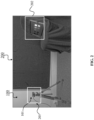
- FIG. 2 is a schematic view of a system 200 for determining a noise profile for the device 100.
- a noise profile for an image sensor 101 of the device 100 may be determined.
- the system 200 may be based the device 100, or the device 100 may be incorporated in the system 200. Without limiting the present disclosure, in following it is assumed that the device 100 is incorporated in the system 200. Moreover, the device 100 is exemplarily based on (e.g., comprising) a computer vision digital camera 201 (for example, it comprises the CV digital camera 201 which comprises the image sensor 101). The system 200 further comprises a light box 202 with square calibration targets of different light emission (right) used to measure the noise characteristic.
- a computer vision digital camera 201 for example, it comprises the CV digital camera 201 which comprises the image sensor 101.
- the system 200 further comprises a light box 202 with square calibration targets of different light emission (right) used to measure the noise characteristic.
- Determining the noise profile of the device 100 may be, for example, estimating a noise profile of the image sensor 101 of the digital camera 201 of the device 100, estimating different parameters of the TF 105, etc.
- Different computer vision methods may be robust to the noise (e.g., photon noise, read-out noise and ADC noise, etc.) introduced by the image sensor 101.
- the system 200 (and/or the device 100) is configured to consider the introduced noises when determining the transfer function 105 and to simulate different exemplary cameras 201 (for several relevant cameras) under different illumination levels. For example, a model (e.g., a noise profile of the image sensor) for the camera noise characteristics may be determined, and the required parameters for the determined model may be estimated.
- a list of the symbols used for determining the noise model are presented in table I.
- Table I List of used symbols for noise model ⁇ electrons per second collected by the sensor k c Per-channel coefficient that converts the number of electrons for each channel to the digital value in the RAW image.
- c can be r or g or b, standing for R,G,B color channels n a normally distributed random variable that models noise t Exposure time g Sensor gain Y max the maximum value that can be registered by a sensor ⁇ read 2 Readout noise ⁇ adc 2 Noise caused by analog-to-digital conversion and quantization
- the image sensor 101 of the camera 201 collects ⁇ electron per second.
- the gain of the image sensor being g
- the symbol n is a normally distributed random variable that models the noises (for example, the photon noise, the read out noise and the ADC noise).
- ⁇ c 2 Y c Y c gk c + ⁇ read 2 g 2 + ⁇ adc 2 ,
- Table II presents the estimated noise parameters fitted for several exemplary cameras (without limiting the present disclosure to a specific camera, a specific image sensor, etc.). All camera RAW images assumed to be 16 bit in order to perform an easier comparison. Table II: Noise parameters fitted for several exemplary cameras. Camera Color Coefficients ⁇ read ⁇ adc k r k g k b Sony ⁇ 7r1 2.236 1.32 5.776 3.198 6.601 Sony ⁇ 7r3 2.235 1.452 5.633 0 7.687 Canon T1i 4.336 2.564 9.482 0.023 52.47 IDS UI-314x 13.68 9.883 8.902 0.5704 1.352
- the device 100 may further determine the transfer function 105.
- the transfer function 105 may be determined by the device 100 (and/or the system 200) by the device 100 (and/or the system 200). In the following, several exemplary procedures for determining the transfer function 105 are presented.
- a majority of camera sensors including CCD and CMOS, exhibits a linear response to light, i.e., they count the number of incoming photons and register values that are linearly related to radiometric quantities (irradiance). Furthermore, since the linear color values are strongly perceptually non-uniform and require high bit-depths to store, they are typically tone-mapped into a gamma-corrected representation.
- the cameras are designed to capture visually pleasant content typically use S-shaped tone-curves, mimicking the response of an analog photographic film. Computer vision cameras more often apply a transfer power function with the exponent less than 1, commonly known as "gamma".
- the system 200 including the device 100
- the although such gamma encoding is suitable for sensors of moderate dynamic range, and for standard displays, this is not the best choice for the image sensors of higher dynamic range and when the images are intended for computer vision methods rather than for viewing.
- the device 100 may determine the TF 105 based on one of the following procedures.
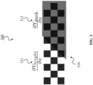
- FIG. 3 is a schematic view of a diagram 300 comprising a checkerboard pattern 310 used for obtaining a logarithmic transform with illumination-invariant gradients.
- the checkerboard pattern 310 is directly illuminated on the left side 311 and in shadow on the right side 312. Moreover, when computing the gradients (e.g., the partial derivative) by the system 200 (and/or the device 100), it is determined that the partial derivatives will be different for both sides when computed in a linear color space.
- the gradients e.g., the partial derivative
- a large portion of computer vision methods does not operate directly on pixel values but rather on gradients.
- the classical descriptors such as the Scale-Invariant Feature Transform (SIFT) or the Histogram of Oriented Gradients (HOG), compute histograms of gradient magnitudes and orientations.
- SIFT Scale-Invariant Feature Transform
- HOG Histogram of Oriented Gradients
- the first convolutional layers in deep neural networks often extract features that represent differences between neighboring pixels. Therefore, preserving gradient values across the range of illumination conditions is considered to be a desirable property of color encoding for computer vision.
- the logarithmic transform may strongly enhance the low color values, which are most affected by the noise. This may introduce strong inconsistencies in the level of noise, and may further break another common assumption of computer vision methods, as will be discussed below.
- the device 100 may determine the TF 105 which may be based on a noise-variance stabilizing transform.
- the TF 105 e.g., the first part 121 of the TF 105
- the noise-variance stabilizing transform the noise-variance TF
- the camera noise i.e., the photon noise, the ADC noise, the readout noise
- the camera noise is normally distributed and has a constant variance across the intensity range.
- This assumption is a reasonable approximation for gamma-corrected 8-bit images, but it may not be used for linear color values coming directly from a camera's image sensor.
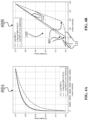
- FIG. 4A and FIG. 4B show examples of the designed OETF curves for determining a noise-adaptive transfer function.
- the device 100 may determine a noise-adaptive transfer function 105 based on the OETF curves.
- the transfer function (TF 105) may also be separated for R, G, B, if a noise profile is measured for each of the color channel. Examples of all the three variants of the proposed OETFs are shown in diagram 400A of FIG.4A and diagram 400B of FIG.4B .
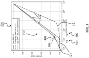
- the curve indicated by "Log-SNR+3” is a logarithmic curve with threshold of 3dB.
- the curve indicated by “2-seg-log SNR+9 SL1/3” is a two segment logarithmic curve with threshold of 9dB in SNR and the ratio between two slopes is 1 to 3.
- the curve indicated by "Log-SNR+25_Var-stablizing” is a combination of logarithmic and variance-stabilizing method with a threshold of 25dB in SNR.
- the diagram 400A of FIG.4A refers to encoded value vs linear intensity
- the diagram 400B of FIG.4B refers to encoded value vs logarithmic of the intensity values. They are equivalent.
- the linear intensity values are pixel values in R or G or B.
- the device 100 may determine the TF 105 by using a logarithmic TF only for the digital values that are above a certain SNR and clamp to zero the values that are too noisy to be useful for a computer vision application.
- the choice of an SNR threshold may offer a trade-off between using higher precision to represent high digital values and clipping a certain portion of the lower digital range.
- the first part 121 (0) of the TF 105 ( E log-snr-x ( Y )) is determined for Y ⁇ T (indicated with reference number 401 in FIG. 4 and FIG. 5 ), and the second part 122 ((log( Y ) - log( T )) ⁇ s ) of the TF 105 ( E log-snr-x ( Y )) is determined for Y ⁇ T 401 .
- x 10 log 10 T 2 ⁇ 2 T
- the SNR threshold x is to be set based on sensor noise profile and the application. Recommended value range is [-3dB, +3dB]. Given x, T 401 can be computed using an inverse operation.
- logarithmic function herein, a natural log is written for simplicity. Also, a logarithmic function with any basis value, like log2 or log10 may also work, and the output of the transfer function 105 may be the same no matter which logarithmic basis is taken.
- the input value Y here can either represent the luminance value or the value of one color channel, R or G or B.
- the subscript of c for color channels is omitted.
- a limitation of the noise-adaptive transfer function determined based on Eq. (4) may be that the values below the SNR threshold are set to zero and (all) information being lost. Still, some computer vision algorithms can extract information even from such very noisy signal. Therefore, it is desirable to preserve even the low SNR range. However, allocating too large range in the encoded values to the noisy part of the intensity range would reduce contrast in the brighter part of the intensity range, and lower performance of the computer vision algorithms in that range.
- the device 100 may split the TF 105 into two logarithmic segments (i.e., the first part 121 of the TF 105 determined for the low-SNR segment (low intensity values) and the second part 122 of the TF 105 determined for the high-SNR segment (high intensity values) are both logarithmic functions.
- the transition between the two parts is selected (e.g., as before) based on the SNR threshold.
- the slope refers to the tangent of the mapping function in the log-linear coordinates.
- the device 100 may determine the TF 105 ( E 2 seg-log ( Y )) according to Eq.
- This value may be adjusted by the device (i.e., the user of device) based on image sensors and the CV applications. For example, the recommended value is 0.1.
- the TF 105 ( E 2 seg-log ( Y )) comprises the first part 121 (log( Y ) ⁇ r ⁇ s ) that is determined for Y ⁇ T (indicated with reference number 401 in FIG. 4 and FIG. 5 ), and the second part ((log( Y ) - log( T ) ⁇ (1 - r )) ⁇ s ) that is determined for Y ⁇ T 401.
- determining the TF 105 based on the two parts logarithmic curve may be that the transfer function 105 is incontinuous at the conjunction point T 401.
- the slope of the second part (being used for determining the second part 122 of the TF 105) is generally a few times higher than the first part (being used for determining the first part 121 of the TF 105), and thus the transition at T 401 is rather abrupt.
- the device 100 may extend the two parts logarithmic transform (TF) with a smooth transition between two parts.
- the device 100 may introduce a smoothing function 106 (e.g. a cubic function) for this purpose and may further fit in with the two segments at a first lower threshold (T 1 ) 501 and a first upper threshold (T 2 ) 502.
- An example of smoothing the two parts of the designed OETF curve is illustrated in FIG. 5 (for example the device 100 may performs the smoothing operation).
- the device 100 may (uniquely) determine the four parameters, i.e., a, b, c and d of the cubic function P(Y), using the four boundary conditions according to Eq. (10) to Eq. (13) as follow:
- P T 1 L 1 T 1 and
- P T 2 L 2 T 2 and
- dP Y dY T 1 dL 1 Y dY T 1 and
- dP Y dY T 2 dL 2 Y dY T 2
- the device 100 may determine the TF 105, for example, based on the two-segment logarithmic transfer function and the noise-variance stabilizing transfer function.
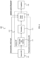
- FIG. 6 is a schematic view of the device 100 comprising a TF 105 used in an image signal processing pipeline 610 of a camera, according to an embodiment of the present invention.
- the device 100 of FIG. 6 is exemplary based on a CV digital camera. Moreover, the TF 105 is used (incorporated) in the image signal processing modules of the device 100 (camera).
- the image signal processing (ISP) herein does not refer to a general concept of processing the image, but the specific systems in cameras, which convert sensor raw data, typical Bayer-pattern but possibly also other formats, to standard RGB or YUV format, which are appropriate for image and video storage in typical formats (for example, known conventional formats such as Joint Photographic Experts Group (JPEG), Portable Network Graphics (PNG), MPEG Layer-4 Audio (MP4), MKV, etc.).
- JPEG Joint Photographic Experts Group
- PNG Portable Network Graphics
- MP4 MPEG Layer-4 Audio
- MKV MKV
- the camera ISP 610 is using the transfer function 105 as it is depicted in FIG. 6 .
- the raw data comes from the image sensor 101 (i.e., in FIG. 6 the image sensor and the ADC are in one unit) and goes into the camera ISP unit 610.
- Camera ISP unit 610 comprises the fixed pattern noise suppression unit 611 (may perform a denoising operation), and the demosaicing unit 612 and the determined TF 105.
- the output of the camera ISP 610 is sent to the computer vision application unit 603, e.g., for face detection, face recognition, object detection, etc.
- the implementation of the transfer function 105 may depend on three parameters.
- the first parameter is the image sensor noise profile, which is computed offline.
- the second parameter is the image sensor's gain. This parameter is either determined automatically by the camera based on illumination or other conditions or it may be set by the camera's user.
- the third parameter is the SNR value, and these values determines the threshold value T 401 in the TF 105.
- the SNR parameter is related to the CV application and is preset for every different CV application.
- FIG. 7 is a schematic view of a flowchart of a procedure 700 for determining the OETF component.
- the device 100 obtains the gain value (g) from the image sensor 101. For example, it may obtained dynamically.
- the device 100 computes the SNR threshold (x) or receive it from the user's settings. For example, it may be computed dynamically.
- the device 100 computes the OETF threshold (T) 401 using the SNR threshold (x) and the noise profile of the image sensor.
- the noise profile may be computed offline, and may further be stored in the camera and remains the same.
- the device 100 determines the parameters for the two segments of the OETF curve (the first part 121 and the second part 122 of the TF 105).
- the device 100 may compute the OETF again.
- the OETF curve may be used for determining the TF 105, e.g., the first part 121 of the TF 105 and/or the second part 122 of the TF 105.
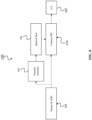
- FIG. 8 is a schematic view of the device 100 comprising a TF 105 used for generating optical flows for Bayer-pattern raw data, according to an embodiment of the present invention.
- the device 100 may determine the TF 105 that may help generating optical flows for Bayer-pattern raw data. For example, the determined TF 105 is used to generate more accurate optical flow to assist the camera's ISP 610. For instance the transfer function 105 can also be used in the camera ISP 610 herein with a different parameter setting.
- the transfer function 105 is applied at an early stage of the device 100, i.e., directly applied to the raw data of the image sensor 101.
- the optical flow is generated using the output of the transfer function 105.
- the generated optical flow is forwarded to the camera's ISP 610. Note that, not all camera's ISP 610 depends on the transfer function 105, but some of the camera ISP may benefit from optical flow 801.
- the output of the camera ISP 610 is sent to the CV application unit 603.
- one function of the transfer function 105 is a pre-processing step of the raw data for optical flow 801. In this manner, the accuracy of the output of the optical flow unit 801 is expected to be improved. Higher accuracy of optical flow may lead to better quality of camera ISP output images. Finally, a higher accuracy of CV applications is expected.
- the transfer function 105 may also be used in the camera ISP, for example, similar to the embodiment of FIG. 6 , and for the parameter setting, the gain is the same and the SNR threshold may be different.
- FIG. 9 is a schematic view of the device 100 comprising a TF 105 used on the sensor side and in a camera module 901 for performing a bit depth compression according to an embodiment of the present invention.
- the device 100 determines the TF 105. Moreover, the transfer function 105 is used on the image sensor 101 side and in the camera's module 901 before compressing or quantizing the HDR raw data to lower bit depths.
- the transfer function 105 may be used to solve the issue of limited bandwidth between the camera module 901 and the camera's ISP 610.
- the standard connection interface is the Mobile Industry Processor Interface (MIPI) / the Camera Serial Interface (CSI).
- MIPI Mobile Industry Processor Interface
- CSI Camera Serial Interface
- the HDR camera sensor data are often 20 bits or 24 bits, and there is a trend for even higher bit depth. Therefore, the HDR image data are quantized to 12 bit in this scenario. Direct compression of the image sensor data, however, results in poor performance. And the transfer function 105 may be used before quantization.
- the HDR sensor raw data e.g. 24 bits
- the HDR sensor raw data is transformed to nonlinear domain using the determined transfer function 105.
- it may be quantized or compressed to low bit depth, e.g., 12 bit to fit in the MIPI/CSI standard.
- low bit depth e.g. 12 bit to fit in the MIPI/CSI standard.
- it may be uniform scalar quantization.
- there may be no predictive coding, no entropy coding, etc.
- the camera ISP pipeline 610 comprises the inverse of the transfer function 920 and the other ISP components 902.
- the inverse of the transfer function 920 is applied and 24 bit HDR raw data in the linear domain are reconstructed. For example, it is converted back to linear domain, because of the ISP processes linear data.
- These data may be further processed by the ISP pipeline and the output is used in CV applications unit 603.
- the role of the transfer function 105 in this embodiment may be to reduce the distortion between the original 24 bit data and the reconstructed 24 bit data for CV.
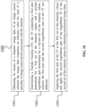
- FIG. 10 shows a method 1000 according to an embodiment of the invention for pre-processing image data 103 for a computer vision application 140.
- the method 1000 may be carried out by the device 100, as it is described above.
- the method 1000 comprises a step 1001 of obtaining, by means of a channel 102, image data 103 of an image sensor 101, wherein the image data 103 comprises an intensity value for each of a plurality of image sensor pixels associated with the channel 102.
- the method 1000 further comprises a step 1002 of determining a TF 105, the TF 105 comprising a first part 121 determined for a first set of the intensity values, and a second logarithmic part 122 determined for a second set of the intensity values, wherein the first part 121 and the second part 122 of the TF 105 are different.
- the method 1000 further comprises a step 1003 of applying the first part 121 of the TF 105 to the first set of the intensity values and apply the second logarithmic part 122 of the TF 105 to the second set of the intensity values, in order to obtain transformed image data 104.
Landscapes
- Physics & Mathematics (AREA)
- General Physics & Mathematics (AREA)
- Engineering & Computer Science (AREA)
- Theoretical Computer Science (AREA)
- Image Processing (AREA)
Claims (13)
- Vorrichtung (100) zum Vorverarbeiten von Bilddaten (103) für eine Computersichtanwendung (140), wobei die Vorrichtung (100) dazu ausgelegt ist:mittels eines Kanals (102) Bilddaten (103) eines Bildsensors (101) zu erhalten, wobei die Bilddaten (103) einen Intensitätswert für jeden einer Vielzahl von dem Kanal (102) zugeordneten Bildsensorpixeln umfassen,eine Übertragungsfunktion (105), TF, zu bestimmen, wobei die TF (105) einen ersten Teil (121), der für einen ersten Satz der Intensitätswerte bestimmt ist, und einen zweiten, logarithmischen Teil (122), der für einen zweiten Satz der Intensitätswerte bestimmt ist, umfasst, wobei der erste Teil (121) und der zweite Teil (122) der TF (105) verschieden sind, undden ersten Teil (121) der TF (105) auf den ersten Satz der Intensitätswerte anzuwenden und den zweiten, logarithmischen Teil (122) der TF (105) auf den zweiten Satz der Intensitätswerte anzuwenden, um transformierte Bilddaten (104) zu erhalten;dadurch gekennzeichnet, dassdie Vorrichtung ferner dazu ausgelegt ist, einen Schwellenintensitätswert (401), der die TF (105) in den ersten Teil (121) und den zweiten Teil (122) der TF (105) unterteilt, basierend auf einem SNR-Schwellenwert zu bestimmen.
- Vorrichtung (100) nach Anspruch 1, wobei:
basierend auf einer logarithmischen Skala eine Steigung der TF (105) im ersten Teil (121) kleiner als eine Steigung der TF (105) im zweiten, logarithmischen Teil (122) ist. - Vorrichtung (100) nach Anspruch 1 oder 2, wobei:der erste Teil (121) der TF (105) auf einer logarithmischen Funktion basiert, oderder erste Teil (121) der TF (105) ein konstanter Wert ist.
- Vorrichtung (100) nach einem der Ansprüche 1-3, wobei:
der SNR-Schwellenwert einen Wert im Bereich von -3 dB bis +3 dB aufweist. - Vorrichtung (100) nach einem der Ansprüche 1 bis 4, wobei:
die TF (105) basierend auf einem Rauschprofil des Bildsensors (101) bestimmt wird. - Vorrichtung (100) nach einem der Ansprüche 1 bis 5, wobei:
der SNR-Schwellenwert basierend auf einem Rauschprofil des Bildsensors (101) erhalten wird. - Vorrichtung (100) nach einem der Ansprüche 1 bis 6, ferner dazu ausgelegt:eine Glättungsfunktion (106) in die TF (105) einzuführen, um den Schwellenintensitätswert (401) zu einem Schwellenbereich zu erweitern, der einen ersten unteren Schwellenwert (501) und einen ersten oberen Schwellenwert (502) umfasst,wobei die Glättungsfunktion (106) zum Ersetzen der TF (105) im Schwellenwertbereich dient, undwobei das Ersetzen der TF (105) im Schwellenwertbereich durch die Glättungsfunktion (106) bewirkt, dass die TF für beliebige Intensitätswerte differenzierbar ist.
- Vorrichtung (100) nach Anspruch 7, wobei:
die Glättungsfunktion (106) auf einer kubischen Funktion basiert. - Vorrichtung (100) nach Anspruch 7 oder 8, ferner dazu ausgelegt:
ein Verhältnis des ersten Teils (121) zum zweiten Teil (122) der TF (105) zu erhalten, wobei es vom Verhältnis des ersten Teils (121) zum zweiten Teil (122) der TF (105) abhängt, ob das Ersetzen der TF (105) im Schwellenwertbereich durch die Glättungsfunktion (106) stattfindet. - Vorrichtung (100) nach einem der Ansprüche 1 bis 9, ferner dazu ausgelegt:
eine inverse logarithmische TF auf die übertragenen Bilddaten anzuwenden, um Bilddaten oder Videodaten in einem bestimmten Format gemäß der Computersichtanwendung (140) zu erhalten. - Vorrichtung (100) nach einem der Ansprüche 1 bis 10, wobei:- die Vorrichtung in einem von Folgendem implementiert ist:- einem Bildsignalverarbeitungs-, ISP-, Modul einer Bildgebungsvorrichtung,- einem Teil einer optischen Flusserzeugung für eine ISP einer Bildgebungsvorrichtung,- einem Kameramodul einer Bildgebungsvorrichtung mit hohem Dynamikbereich, HDR.
- Computerimplementiertes Verfahren (1000) zum Vorverarbeiten von Bilddaten (103) für eine Computersichtanwendung (140), wobei das Verfahren (1000) die folgenden Schritte umfasst:Erhalten (1001) von Bilddaten (103) eines Bildsensors (101) mittels eines Kanals (102), wobei die Bilddaten (103) einen Intensitätswert für jeden einer Vielzahl von dem Kanal (102) zugeordneten Bildsensorpixeln umfassen,Bestimmen (1002) einer Übertragungsfunktion (105), TF, wobei die TF (105) einen ersten Teil (121), der für einen ersten Satz der Intensitätswerte bestimmt wird, und einen zweiten, logarithmischen Teil (122), der für einen zweiten Satz der Intensitätswerte bestimmt wird, umfasst, wobei der erste Teil (121) und der zweite Teil (122) der TF (105) verschieden sind, undAnwenden (1003) des ersten Teils (121) der TF (105) auf den ersten Satz der Intensitätswerte und Anwenden des zweiten, logarithmischen Teils (122) der TF (105) auf den zweiten Satz der Intensitätswerte, um transformierte Bilddaten (104) zu erhalten;dadurch gekennzeichnet, dassdas Verfahren ferner umfasst: Bestimmen eines Schwellenintensitätswerts (401), der die TF (105) basierend auf einem SNR-Schwellenwert in den ersten Teil (121) und den zweiten Teil (122) der TF (105) unterteilt.
- Computerprogramm, umfassend Anweisungen, die, wenn das Programm durch einen Computer ausgeführt wird, den Computer veranlassen, das Verfahren (1000) nach Anspruch 12 durchzuführen.
Applications Claiming Priority (1)
| Application Number | Priority Date | Filing Date | Title |
|---|---|---|---|
| PCT/EP2019/081554 WO2021093980A1 (en) | 2019-11-15 | 2019-11-15 | Device and method for pre-processing image data for a computer vision application |
Publications (2)
| Publication Number | Publication Date |
|---|---|
| EP4058976A1 EP4058976A1 (de) | 2022-09-21 |
| EP4058976B1 true EP4058976B1 (de) | 2025-05-07 |
Family
ID=68583439
Family Applications (1)
| Application Number | Title | Priority Date | Filing Date |
|---|---|---|---|
| EP19805281.3A Active EP4058976B1 (de) | 2019-11-15 | 2019-11-15 | Vorrichtung und verfahren zum vorverarbeiten von bilddaten für eine computersichtanwendung |
Country Status (2)
| Country | Link |
|---|---|
| EP (1) | EP4058976B1 (de) |
| WO (1) | WO2021093980A1 (de) |
Families Citing this family (1)
| Publication number | Priority date | Publication date | Assignee | Title |
|---|---|---|---|---|
| WO2023280424A1 (en) * | 2021-07-09 | 2023-01-12 | Huawei Technologies Co., Ltd. | Devices and methods for processing image data |
Family Cites Families (3)
| Publication number | Priority date | Publication date | Assignee | Title |
|---|---|---|---|---|
| EP2445214A1 (de) * | 2010-10-19 | 2012-04-25 | Fraunhofer-Gesellschaft zur Förderung der angewandten Forschung e.V. | Videocodierung mithilfe einer temporär kohärenten dynamischen Bereichskartierung |
| EP3131284A1 (de) * | 2015-08-13 | 2017-02-15 | Thomson Licensing | Verfahren, systeme und vorrichtungen für inverse hdr-zu-hdr-bilddynamikkompression |
| US10275864B2 (en) * | 2016-09-09 | 2019-04-30 | Kabushiki Kaisha Toshiba | Image processing device and image processing method |
-
2019
- 2019-11-15 EP EP19805281.3A patent/EP4058976B1/de active Active
- 2019-11-15 WO PCT/EP2019/081554 patent/WO2021093980A1/en not_active Ceased
Also Published As
| Publication number | Publication date |
|---|---|
| WO2021093980A1 (en) | 2021-05-20 |
| EP4058976A1 (de) | 2022-09-21 |
Similar Documents
| Publication | Publication Date | Title |
|---|---|---|
| JP5965025B2 (ja) | Hdr画像のための画像処理 | |
| US8169500B2 (en) | Dynamic range compression apparatus, dynamic range compression method, computer-readable recording medium, integrated circuit, and imaging apparatus | |
| US9681026B2 (en) | System and method for lens shading compensation | |
| TWI473039B (zh) | 影像的動態範圍壓縮與局部對比增強方法及影像處理裝置 | |
| CN100366052C (zh) | 图像处理设备和方法 | |
| EP3669542B1 (de) | Effiziente bittiefenbildverarbeitung | |
| CN109118436B (zh) | 图像色调适配方法及相应的电子设备和存储介质 | |
| JP2018019239A (ja) | 撮像装置及びその制御方法及びプログラム | |
| CN115499632B (zh) | 一种图像信号转换处理方法、装置及终端设备 | |
| US10742986B2 (en) | High dynamic range color conversion correction | |
| EP4058976B1 (de) | Vorrichtung und verfahren zum vorverarbeiten von bilddaten für eine computersichtanwendung | |
| CN115052137A (zh) | 一种视频信号处理方法及装置 | |
| Adams Jr et al. | Digital camera image processing chain design | |
| KR102282464B1 (ko) | 영상 처리 장치 및 영상 처리 방법 | |
| US10715772B2 (en) | High dynamic range color conversion correction | |
| Narasimha et al. | A real-time high dynamic range HD video camera | |
| WO2023280424A1 (en) | Devices and methods for processing image data | |
| CN118103864A (zh) | 一种用于噪声自适应高动态范围图像处理的设备和方法 | |
| KR20150127524A (ko) | 영상 처리 장치 및 영상 처리 방법 | |
| JP2021048522A (ja) | 画像処理装置および画像処理方法 | |
| WO2019071045A1 (en) | HIGH DYNAMIC RANGE COLORING CORRECTION | |
| HK1194185A (en) | Image processing for hdr images | |
| HK1194185B (en) | Image processing for hdr images |
Legal Events
| Date | Code | Title | Description |
|---|---|---|---|
| STAA | Information on the status of an ep patent application or granted ep patent |
Free format text: STATUS: UNKNOWN |
|
| STAA | Information on the status of an ep patent application or granted ep patent |
Free format text: STATUS: THE INTERNATIONAL PUBLICATION HAS BEEN MADE |
|
| PUAI | Public reference made under article 153(3) epc to a published international application that has entered the european phase |
Free format text: ORIGINAL CODE: 0009012 |
|
| STAA | Information on the status of an ep patent application or granted ep patent |
Free format text: STATUS: REQUEST FOR EXAMINATION WAS MADE |
|
| 17P | Request for examination filed |
Effective date: 20220615 |
|
| AK | Designated contracting states |
Kind code of ref document: A1 Designated state(s): AL AT BE BG CH CY CZ DE DK EE ES FI FR GB GR HR HU IE IS IT LI LT LU LV MC MK MT NL NO PL PT RO RS SE SI SK SM TR |
|
| DAV | Request for validation of the european patent (deleted) | ||
| DAX | Request for extension of the european patent (deleted) | ||
| REG | Reference to a national code |
Ref country code: DE Ref legal event code: R079 Free format text: PREVIOUS MAIN CLASS: G06T0005000000 Ipc: G06T0005700000 Ref country code: DE Ref legal event code: R079 Ref document number: 602019069707 Country of ref document: DE Free format text: PREVIOUS MAIN CLASS: G06T0005000000 Ipc: G06T0005700000 |
|
| GRAP | Despatch of communication of intention to grant a patent |
Free format text: ORIGINAL CODE: EPIDOSNIGR1 |
|
| STAA | Information on the status of an ep patent application or granted ep patent |
Free format text: STATUS: GRANT OF PATENT IS INTENDED |
|
| RIC1 | Information provided on ipc code assigned before grant |
Ipc: G06T 5/94 20240101ALI20241114BHEP Ipc: G06T 5/70 20240101AFI20241114BHEP |
|
| INTG | Intention to grant announced |
Effective date: 20241202 |
|
| GRAS | Grant fee paid |
Free format text: ORIGINAL CODE: EPIDOSNIGR3 |
|
| GRAA | (expected) grant |
Free format text: ORIGINAL CODE: 0009210 |
|
| STAA | Information on the status of an ep patent application or granted ep patent |
Free format text: STATUS: THE PATENT HAS BEEN GRANTED |
|
| AK | Designated contracting states |
Kind code of ref document: B1 Designated state(s): AL AT BE BG CH CY CZ DE DK EE ES FI FR GB GR HR HU IE IS IT LI LT LU LV MC MK MT NL NO PL PT RO RS SE SI SK SM TR |
|
| REG | Reference to a national code |
Ref country code: GB Ref legal event code: FG4D |
|
| REG | Reference to a national code |
Ref country code: CH Ref legal event code: EP |
|
| REG | Reference to a national code |
Ref country code: DE Ref legal event code: R096 Ref document number: 602019069707 Country of ref document: DE |
|
| REG | Reference to a national code |
Ref country code: IE Ref legal event code: FG4D |
|
| REG | Reference to a national code |
Ref country code: NL Ref legal event code: MP Effective date: 20250507 |
|
| PG25 | Lapsed in a contracting state [announced via postgrant information from national office to epo] |
Ref country code: ES Free format text: LAPSE BECAUSE OF FAILURE TO SUBMIT A TRANSLATION OF THE DESCRIPTION OR TO PAY THE FEE WITHIN THE PRESCRIBED TIME-LIMIT Effective date: 20250507 Ref country code: PT Free format text: LAPSE BECAUSE OF FAILURE TO SUBMIT A TRANSLATION OF THE DESCRIPTION OR TO PAY THE FEE WITHIN THE PRESCRIBED TIME-LIMIT Effective date: 20250908 Ref country code: FI Free format text: LAPSE BECAUSE OF FAILURE TO SUBMIT A TRANSLATION OF THE DESCRIPTION OR TO PAY THE FEE WITHIN THE PRESCRIBED TIME-LIMIT Effective date: 20250507 |
|
| REG | Reference to a national code |
Ref country code: LT Ref legal event code: MG9D |
|
| PG25 | Lapsed in a contracting state [announced via postgrant information from national office to epo] |
Ref country code: NO Free format text: LAPSE BECAUSE OF FAILURE TO SUBMIT A TRANSLATION OF THE DESCRIPTION OR TO PAY THE FEE WITHIN THE PRESCRIBED TIME-LIMIT Effective date: 20250807 Ref country code: GR Free format text: LAPSE BECAUSE OF FAILURE TO SUBMIT A TRANSLATION OF THE DESCRIPTION OR TO PAY THE FEE WITHIN THE PRESCRIBED TIME-LIMIT Effective date: 20250808 |
|
| PG25 | Lapsed in a contracting state [announced via postgrant information from national office to epo] |
Ref country code: PL Free format text: LAPSE BECAUSE OF FAILURE TO SUBMIT A TRANSLATION OF THE DESCRIPTION OR TO PAY THE FEE WITHIN THE PRESCRIBED TIME-LIMIT Effective date: 20250507 Ref country code: NL Free format text: LAPSE BECAUSE OF FAILURE TO SUBMIT A TRANSLATION OF THE DESCRIPTION OR TO PAY THE FEE WITHIN THE PRESCRIBED TIME-LIMIT Effective date: 20250507 |
|
| REG | Reference to a national code |
Ref country code: AT Ref legal event code: MK05 Ref document number: 1793317 Country of ref document: AT Kind code of ref document: T Effective date: 20250507 |
|
| PG25 | Lapsed in a contracting state [announced via postgrant information from national office to epo] |
Ref country code: BG Free format text: LAPSE BECAUSE OF FAILURE TO SUBMIT A TRANSLATION OF THE DESCRIPTION OR TO PAY THE FEE WITHIN THE PRESCRIBED TIME-LIMIT Effective date: 20250507 |
|
| PG25 | Lapsed in a contracting state [announced via postgrant information from national office to epo] |
Ref country code: HR Free format text: LAPSE BECAUSE OF FAILURE TO SUBMIT A TRANSLATION OF THE DESCRIPTION OR TO PAY THE FEE WITHIN THE PRESCRIBED TIME-LIMIT Effective date: 20250507 |
|
| PG25 | Lapsed in a contracting state [announced via postgrant information from national office to epo] |
Ref country code: AT Free format text: LAPSE BECAUSE OF FAILURE TO SUBMIT A TRANSLATION OF THE DESCRIPTION OR TO PAY THE FEE WITHIN THE PRESCRIBED TIME-LIMIT Effective date: 20250507 |
|
| PG25 | Lapsed in a contracting state [announced via postgrant information from national office to epo] |
Ref country code: RS Free format text: LAPSE BECAUSE OF FAILURE TO SUBMIT A TRANSLATION OF THE DESCRIPTION OR TO PAY THE FEE WITHIN THE PRESCRIBED TIME-LIMIT Effective date: 20250807 |
|
| PG25 | Lapsed in a contracting state [announced via postgrant information from national office to epo] |
Ref country code: IS Free format text: LAPSE BECAUSE OF FAILURE TO SUBMIT A TRANSLATION OF THE DESCRIPTION OR TO PAY THE FEE WITHIN THE PRESCRIBED TIME-LIMIT Effective date: 20250907 |
|
| PG25 | Lapsed in a contracting state [announced via postgrant information from national office to epo] |
Ref country code: LV Free format text: LAPSE BECAUSE OF FAILURE TO SUBMIT A TRANSLATION OF THE DESCRIPTION OR TO PAY THE FEE WITHIN THE PRESCRIBED TIME-LIMIT Effective date: 20250507 |
|
| PGFP | Annual fee paid to national office [announced via postgrant information from national office to epo] |
Ref country code: DE Payment date: 20250930 Year of fee payment: 7 |
|
| PG25 | Lapsed in a contracting state [announced via postgrant information from national office to epo] |
Ref country code: SM Free format text: LAPSE BECAUSE OF FAILURE TO SUBMIT A TRANSLATION OF THE DESCRIPTION OR TO PAY THE FEE WITHIN THE PRESCRIBED TIME-LIMIT Effective date: 20250507 Ref country code: DK Free format text: LAPSE BECAUSE OF FAILURE TO SUBMIT A TRANSLATION OF THE DESCRIPTION OR TO PAY THE FEE WITHIN THE PRESCRIBED TIME-LIMIT Effective date: 20250507 |
|
| PG25 | Lapsed in a contracting state [announced via postgrant information from national office to epo] |
Ref country code: CZ Free format text: LAPSE BECAUSE OF FAILURE TO SUBMIT A TRANSLATION OF THE DESCRIPTION OR TO PAY THE FEE WITHIN THE PRESCRIBED TIME-LIMIT Effective date: 20250507 |
|
| PG25 | Lapsed in a contracting state [announced via postgrant information from national office to epo] |
Ref country code: EE Free format text: LAPSE BECAUSE OF FAILURE TO SUBMIT A TRANSLATION OF THE DESCRIPTION OR TO PAY THE FEE WITHIN THE PRESCRIBED TIME-LIMIT Effective date: 20250507 |
|
| PG25 | Lapsed in a contracting state [announced via postgrant information from national office to epo] |
Ref country code: SK Free format text: LAPSE BECAUSE OF FAILURE TO SUBMIT A TRANSLATION OF THE DESCRIPTION OR TO PAY THE FEE WITHIN THE PRESCRIBED TIME-LIMIT Effective date: 20250507 |
|
| PG25 | Lapsed in a contracting state [announced via postgrant information from national office to epo] |
Ref country code: IT Free format text: LAPSE BECAUSE OF FAILURE TO SUBMIT A TRANSLATION OF THE DESCRIPTION OR TO PAY THE FEE WITHIN THE PRESCRIBED TIME-LIMIT Effective date: 20250507 |
|
| PG25 | Lapsed in a contracting state [announced via postgrant information from national office to epo] |
Ref country code: RO Free format text: LAPSE BECAUSE OF FAILURE TO SUBMIT A TRANSLATION OF THE DESCRIPTION OR TO PAY THE FEE WITHIN THE PRESCRIBED TIME-LIMIT Effective date: 20250507 |
|
| REG | Reference to a national code |
Ref country code: DE Ref legal event code: R097 Ref document number: 602019069707 Country of ref document: DE |
|
| PLBE | No opposition filed within time limit |
Free format text: ORIGINAL CODE: 0009261 |
|
| STAA | Information on the status of an ep patent application or granted ep patent |
Free format text: STATUS: NO OPPOSITION FILED WITHIN TIME LIMIT |
|
| REG | Reference to a national code |
Ref country code: CH Ref legal event code: L10 Free format text: ST27 STATUS EVENT CODE: U-0-0-L10-L00 (AS PROVIDED BY THE NATIONAL OFFICE) Effective date: 20260318 |
|
| 26N | No opposition filed |
Effective date: 20260210 |