EP4058758B1 - Modulare und autonome anordnung zur erfassung der winkelposition der schaufeln eines laufrades und modulare und autonome anordnung zum erkennen von schäden an den schaufeln eines laufrades eines turbinenmotors - Google Patents
Modulare und autonome anordnung zur erfassung der winkelposition der schaufeln eines laufrades und modulare und autonome anordnung zum erkennen von schäden an den schaufeln eines laufrades eines turbinenmotors Download PDFInfo
- Publication number
- EP4058758B1 EP4058758B1 EP20823894.9A EP20823894A EP4058758B1 EP 4058758 B1 EP4058758 B1 EP 4058758B1 EP 20823894 A EP20823894 A EP 20823894A EP 4058758 B1 EP4058758 B1 EP 4058758B1
- Authority
- EP
- European Patent Office
- Prior art keywords
- blades
- impeller
- sensor
- assembly
- modular
- Prior art date
- Legal status (The legal status is an assumption and is not a legal conclusion. Google has not performed a legal analysis and makes no representation as to the accuracy of the status listed.)
- Active
Links
Images



Classifications
-
- G—PHYSICS
- G01—MEASURING; TESTING
- G01M—TESTING STATIC OR DYNAMIC BALANCE OF MACHINES OR STRUCTURES; TESTING OF STRUCTURES OR APPARATUS, NOT OTHERWISE PROVIDED FOR
- G01M5/00—Investigating the elasticity of structures, e.g. deflection of bridges or air-craft wings
- G01M5/0033—Investigating the elasticity of structures, e.g. deflection of bridges or air-craft wings by determining damage, crack or wear
-
- F—MECHANICAL ENGINEERING; LIGHTING; HEATING; WEAPONS; BLASTING
- F01—MACHINES OR ENGINES IN GENERAL; ENGINE PLANTS IN GENERAL; STEAM ENGINES
- F01D—NON-POSITIVE DISPLACEMENT MACHINES OR ENGINES, e.g. STEAM TURBINES
- F01D17/00—Regulating or controlling by varying flow
- F01D17/02—Arrangement of sensing elements
-
- F—MECHANICAL ENGINEERING; LIGHTING; HEATING; WEAPONS; BLASTING
- F01—MACHINES OR ENGINES IN GENERAL; ENGINE PLANTS IN GENERAL; STEAM ENGINES
- F01D—NON-POSITIVE DISPLACEMENT MACHINES OR ENGINES, e.g. STEAM TURBINES
- F01D17/00—Regulating or controlling by varying flow
- F01D17/02—Arrangement of sensing elements
- F01D17/06—Arrangement of sensing elements responsive to speed
-
- F—MECHANICAL ENGINEERING; LIGHTING; HEATING; WEAPONS; BLASTING
- F01—MACHINES OR ENGINES IN GENERAL; ENGINE PLANTS IN GENERAL; STEAM ENGINES
- F01D—NON-POSITIVE DISPLACEMENT MACHINES OR ENGINES, e.g. STEAM TURBINES
- F01D21/00—Shutting-down of machines or engines, e.g. in emergency; Regulating, controlling, or safety means not otherwise provided for
- F01D21/003—Arrangements for testing or measuring
-
- F—MECHANICAL ENGINEERING; LIGHTING; HEATING; WEAPONS; BLASTING
- F01—MACHINES OR ENGINES IN GENERAL; ENGINE PLANTS IN GENERAL; STEAM ENGINES
- F01D—NON-POSITIVE DISPLACEMENT MACHINES OR ENGINES, e.g. STEAM TURBINES
- F01D21/00—Shutting-down of machines or engines, e.g. in emergency; Regulating, controlling, or safety means not otherwise provided for
- F01D21/04—Shutting-down of machines or engines, e.g. in emergency; Regulating, controlling, or safety means not otherwise provided for responsive to undesired position of rotor relative to stator or to breaking-off of a part of the rotor, e.g. indicating such position
-
- G—PHYSICS
- G01—MEASURING; TESTING
- G01B—MEASURING LENGTH, THICKNESS OR SIMILAR LINEAR DIMENSIONS; MEASURING ANGLES; MEASURING AREAS; MEASURING IRREGULARITIES OF SURFACES OR CONTOURS
- G01B21/00—Measuring arrangements or details thereof, where the measuring technique is not covered by the other groups of this subclass, unspecified or not relevant
- G01B21/22—Measuring arrangements or details thereof, where the measuring technique is not covered by the other groups of this subclass, unspecified or not relevant for measuring angles or tapers; for testing the alignment of axes
-
- G—PHYSICS
- G01—MEASURING; TESTING
- G01D—MEASURING NOT SPECIALLY ADAPTED FOR A SPECIFIC VARIABLE; ARRANGEMENTS FOR MEASURING TWO OR MORE VARIABLES NOT COVERED IN A SINGLE OTHER SUBCLASS; TARIFF METERING APPARATUS; MEASURING OR TESTING NOT OTHERWISE PROVIDED FOR
- G01D5/00—Mechanical means for transferring the output of a sensing member; Means for converting the output of a sensing member to another variable where the form or nature of the sensing member does not constrain the means for converting; Transducers not specially adapted for a specific variable
- G01D5/12—Mechanical means for transferring the output of a sensing member; Means for converting the output of a sensing member to another variable where the form or nature of the sensing member does not constrain the means for converting; Transducers not specially adapted for a specific variable using electric or magnetic means
- G01D5/244—Mechanical means for transferring the output of a sensing member; Means for converting the output of a sensing member to another variable where the form or nature of the sensing member does not constrain the means for converting; Transducers not specially adapted for a specific variable using electric or magnetic means influencing characteristics of pulses or pulse trains; generating pulses or pulse trains
- G01D5/245—Mechanical means for transferring the output of a sensing member; Means for converting the output of a sensing member to another variable where the form or nature of the sensing member does not constrain the means for converting; Transducers not specially adapted for a specific variable using electric or magnetic means influencing characteristics of pulses or pulse trains; generating pulses or pulse trains using a variable number of pulses in a train
- G01D5/2451—Incremental encoders
- G01D5/2452—Incremental encoders incorporating two or more tracks having an (n, n+1, ...) relationship
-
- G—PHYSICS
- G01—MEASURING; TESTING
- G01M—TESTING STATIC OR DYNAMIC BALANCE OF MACHINES OR STRUCTURES; TESTING OF STRUCTURES OR APPARATUS, NOT OTHERWISE PROVIDED FOR
- G01M15/00—Testing of engines
- G01M15/14—Testing gas-turbine engines or jet-propulsion engines
-
- G—PHYSICS
- G01—MEASURING; TESTING
- G01M—TESTING STATIC OR DYNAMIC BALANCE OF MACHINES OR STRUCTURES; TESTING OF STRUCTURES OR APPARATUS, NOT OTHERWISE PROVIDED FOR
- G01M5/00—Investigating the elasticity of structures, e.g. deflection of bridges or air-craft wings
- G01M5/0016—Investigating the elasticity of structures, e.g. deflection of bridges or air-craft wings of aircraft wings or blades
-
- F—MECHANICAL ENGINEERING; LIGHTING; HEATING; WEAPONS; BLASTING
- F01—MACHINES OR ENGINES IN GENERAL; ENGINE PLANTS IN GENERAL; STEAM ENGINES
- F01D—NON-POSITIVE DISPLACEMENT MACHINES OR ENGINES, e.g. STEAM TURBINES
- F01D5/00—Blades; Blade-carrying members; Heating, heat-insulating, cooling or antivibration means on the blades or the members
- F01D5/12—Blades
- F01D5/28—Selecting particular materials; Particular measures relating thereto; Measures against erosion or corrosion
- F01D5/282—Selecting composite materials, e.g. blades with reinforcing filaments
-
- F—MECHANICAL ENGINEERING; LIGHTING; HEATING; WEAPONS; BLASTING
- F05—INDEXING SCHEMES RELATING TO ENGINES OR PUMPS IN VARIOUS SUBCLASSES OF CLASSES F01-F04
- F05D—INDEXING SCHEME FOR ASPECTS RELATING TO NON-POSITIVE-DISPLACEMENT MACHINES OR ENGINES, GAS-TURBINES OR JET-PROPULSION PLANTS
- F05D2220/00—Application
- F05D2220/30—Application in turbines
- F05D2220/32—Application in turbines in gas turbines
- F05D2220/323—Application in turbines in gas turbines for aircraft propulsion, e.g. jet engines
-
- F—MECHANICAL ENGINEERING; LIGHTING; HEATING; WEAPONS; BLASTING
- F05—INDEXING SCHEMES RELATING TO ENGINES OR PUMPS IN VARIOUS SUBCLASSES OF CLASSES F01-F04
- F05D—INDEXING SCHEME FOR ASPECTS RELATING TO NON-POSITIVE-DISPLACEMENT MACHINES OR ENGINES, GAS-TURBINES OR JET-PROPULSION PLANTS
- F05D2260/00—Function
- F05D2260/80—Diagnostics
-
- F—MECHANICAL ENGINEERING; LIGHTING; HEATING; WEAPONS; BLASTING
- F05—INDEXING SCHEMES RELATING TO ENGINES OR PUMPS IN VARIOUS SUBCLASSES OF CLASSES F01-F04
- F05D—INDEXING SCHEME FOR ASPECTS RELATING TO NON-POSITIVE-DISPLACEMENT MACHINES OR ENGINES, GAS-TURBINES OR JET-PROPULSION PLANTS
- F05D2260/00—Function
- F05D2260/83—Testing, e.g. methods, components or tools therefor
-
- G—PHYSICS
- G01—MEASURING; TESTING
- G01D—MEASURING NOT SPECIALLY ADAPTED FOR A SPECIFIC VARIABLE; ARRANGEMENTS FOR MEASURING TWO OR MORE VARIABLES NOT COVERED IN A SINGLE OTHER SUBCLASS; TARIFF METERING APPARATUS; MEASURING OR TESTING NOT OTHERWISE PROVIDED FOR
- G01D21/00—Measuring or testing not otherwise provided for
Definitions
- the invention relates to the field of monitoring an aircraft engine and more particularly, the identification of the blades of a blade assembly individually, in particular for the detection of possible damage or imbalance on one or more moving blades on a bladed wheel of an aircraft engine.
- the fans of new generations of aircraft engines are equipped with composite blades.
- the integration of these blades into a fan allows a significant improvement in its performance and a significant weight saving.
- a known method of blade damage detection is the use of tip-timing sensors. These sensors detect and count the passage of blades relative to a time base. Tip-timing sensor measurements are then used to calculate the natural frequency of each blade, the natural frequency providing information on the health of the blade.
- this method requires a large number of tip-timing sensors to perform the measurements, as well as significant computing resources to determine the natural frequencies of each blade.
- This solution is therefore only applicable on a test bench, where the integration constraints (e.g.: size, mass, available computing resources) are less.
- the integration constraints e.g.: size, mass, available computing resources
- such a solution is not transposable for a system embedded in an aircraft given the integration constraints and the software resources required. Flight-to-flight monitoring of the health of the blades is therefore not possible without immobilizing the aircraft engine on the ground.
- the identification of individual blades of a blade system is essential both for the balancing of the blades and for the health monitoring functions of the blades. This identification can be done by detecting the so-called “Top-Tour" information.
- the Top-Tour is a fixed reference point, such as an engine crankcase, relative to a rotating element, such as a low pressure shaft or a high pressure shaft.
- This position allows you to know the angular position of the low pressure shaft relative to the casing (in the fixed reference).
- Aircraft engine rotors need to be balanced in order to ensure proper compliance with vibration limits on the engine. To do this, it is necessary to compensate for the measured unbalance, or imbalance, by positioning one or more masses at precise angular positions in the fixed reference frame. The top-turn then makes it possible to define the attachment positions of these masses. The identification made by a man must be consistent with that made by the machine (on-board system) which is in support.
- a method of detecting the top-turn consists of using a sensor, called a top-turn sensor, which detects the passage of teeth, or blades, in its sight and particularly the passage of a singular tooth of the blade (here the toothed wheel) in its sight.
- This toothed wheel called a phonic wheel, is characterized in that it has a singularity, which can be the presence of a localized excess or lack of material on the wheel.
- This anomaly is detected by a means such as a capacitive sensor or a Hall effect sensor for example. The detection of this anomaly makes it possible to know the reference angular position for the entire wheel.
- the tone wheel has no function other than to provide this angular reference and serve as a measuring point for the rotational speed of the rotating parts to which it is attached.
- the phonic wheel does not see any flow. It has no so-called aerodynamic function and therefore does not participate in the propulsion of the engine.
- tone wheel has an impact both on the mass of the aircraft, and even more so when it is rotating, and on the integration given that this specific part is added to the low pressure shaft of the engine and that it is necessary to integrate the sensor up to the tone wheel, in particular with difficulties linked to the implementation tolerances.
- a blade In this process, to obtain the information, a blade must have a different profile in order to be able to generate a different pressure profile.
- the known methods described above also have the disadvantage of generating a positioning of a blade in a non-equi-distributed manner, i.e. angularly non-regular relative to the other blades. It is possible to have a non-equi-distributed distribution of the blades on a blading, but this would also lead to manufacturing constraints and aerodynamic disturbances having a negative impact on the engine performance.
- the known methods described above also have the disadvantage that the sensors must have a bandwidth adequate to detect the passage of all the blades, for all the adopted speed ranges. Indeed, if the speed is too high or if the number of blades is too large, a capacitive sensor will no longer be able to distinguish the blades, and it will be necessary to use an optical sensor for example.
- US2018/224353 discloses a system for monitoring the integrity of turbine engine blades using sensors, which can be removable, modular and autonomous; the vibration measurement data can be used for the detection of an angular position; in this document, the two sensors mounted on the turbine engine are associated with the same turbine engine blade wheel.
- the present invention aims to remedy the aforementioned drawbacks by offering a removable solution independent of the turbomachine computers and the turbomachine power supply and making it possible to generate an angular reference of the top turn type, and to store the signals generated.
- the present invention proposes an assembly, defined in claim 1, modular and autonomous for detecting the angular position of the blades of a bladed wheel, the assembly being intended to be mounted on a turbomachine.
- the assembly comprises at least one electrical power source allowing the operation of the elements of the detection assembly independently of the turbomachine on which it is intended to be installed, at least one first sensor intended to be associated with the first bladed wheel, at least one second sensor intended to be associated with the second impeller, and a main housing comprising a main processing unit and storage means.
- the invention thus makes it possible to provide a solution in the form of a kit independent of any turbomachine with a main housing and various sensors.
- the assembly according to the invention can thus be mechanically fixed on a turbomachine to carry out its angular position detection mission while remaining independent of the turbomachine both in terms of electrical power supply thanks to the power source and information processing capacity thanks to the main processing unit, in other words while remaining independent of the turbomachine computers. And this without having any impact on the operation of the turbomachine.
- the autonomy of the modular measurement assembly provided by the electrical power source makes it possible to install the modular assembly punctually on a turbomachine, and thus reduce the mass impact over time.
- the main housing, said at least one first sensor and said at least one second sensor may each comprise reversible manual fixing means allowing them to be mounted on the turbomachine in a removable manner.
- manual fastening means means allowing fastening on the turbomachine without using any tool.
- Each of the elements of the assembly can thus be easily mounted and dismounted without any tool on the turbomachine.
- Such a detection assembly has a mass of less than one kilogram.
- the modularity of the assembly provided by its removable nature makes it possible to have only a one-off mass impact on the turbomachine and thus to limit the mass impact on a turbomachine in the long term, and by extension on an aircraft, linked to the loading of such an assembly on the turbomachine.
- the monitoring of the blading of a turbomachine does not necessarily have to be carried out continuously. Since the deterioration of the health of the blading to be identified is definitive, a one-off check, at the end of a flight or during a flight, every three flights for example or following an event (for example ingestion of a foreign body), is sufficient.
- the assembly provides all the necessary monitoring equipment for the duration of the check, before being removed from the turbomachine.
- the modularity of the on-board assembly as a Plug & Play kit allows it to be mounted punctually on at least one turbomachine and thus avoid having two on-board systems on the same aircraft.
- the modularity of the assembly also allows the choice of using the assembly only on the ground, which avoids the need for assembly certification, as assembly certification is required for any device carried in flight.
- the storage means allow the data collected by the sensors to be stored for processing in flight by the processing unit of the main unit.
- the storage means also allow the necessary and suitable information to be carried to have the reference base adapted to each monitored blade stage and thus allow in-flight detection to be carried out. With four sensors and a main unit, it is possible, for example, to monitor four stages of the same rotating shaft or two blades of two different shafts.
- each first and second sensor can comprise a detection module, a local processing module, and communication means configured to deliver the measurements of the corresponding sensor to the main processing unit.
- the sensors can have different configurations to be adapted to different environments of a turbomachine.
- the temperature difference between a rear location of the turbine body and that in the compressor position is of the order of 200 to 250°C. Some sensors can thus be configured to withstand the highest temperatures expected.
- each first and second sensor further comprises a power source for the sensor, and the communication means are wireless communication means.
- the use of wireless communication means and a power source for each sensor and for the main housing makes it possible to facilitate the installation of the various elements of the assembly since it avoids having to connect the sensors to the main housing and therefore to pass cables between the various elements.
- the autonomous and modular detection assembly in which the assembly is intended to be mounted on a turbomachine comprises a first impeller comprising a first number of blades and a second impeller comprising a second number, the two impellers each having an air flow passing through them and being directly or indirectly coupled to each other, and the first number of blades of the first impeller and the second number of blades of the second impeller being distinct and prime to each other, said sensors each being configured to generate a signal each time a blade of an impeller passes in front of the sensor, and the main processing unit being configured to determine the time interval separating the detection of a blade of the first impeller with the detection of each of the blades of the second impeller.
- This configuration thus makes it possible to detect the angular position of the blades of a bladed wheel of a turbomachine in the absence of a phonic wheel, which allows a gain in rotating mass and in bulk, or in the absence of a singularity on a blade of the wheel, which makes it possible to avoid introducing an aerodynamic disturbance into the flow of the turbomachine.
- This detection is carried out by using the temporal information of two blades which do not have the same number of blades.
- this detection can be carried out both when the aircraft is on the ground and when it is in flight.
- This configuration advantageously uses the blades already present on the turbomachine shaft and dedicated to propulsion. Comparing the time signal between the two blades thus makes it possible to obtain a Top-Tour type angular reference. Indeed, it is thus possible to form an angular reference from the timing of the blades of the two moving wheels relative to each other.
- comparing the passage time of the blades of the first impeller with the passage time of the blades of the second impeller consecutively makes it possible to identify a pattern, i.e. a signature.
- This signature makes it possible to identify each blade in particular and to define it as the Top-Tour.
- both wheels are driven indirectly by the same shaft.
- the assembly may comprise a determination module intended to determine the rotational speed of the shaft or shafts driving the two impellers, the determination of the relative angular position taking into account the determined rotational speed(s).
- the signature varies depending on the shaft speed. Since the deviations are linked to the distribution of the blades, they can be normalized by the rotation speed with a known number of blades. Also, the Top-Tour detection logic is not dependent on the shaft rotation speed in this sense.
- the assembly may comprise a first sensor and a second sensor intended to be mounted on the first bladed wheel of the turbomachine and a third and a fourth sensor intended to be mounted on the second bladed wheel of the turbomachine, the first and second sensors being of two different types, and the third and fourth sensors being of two different types, the type of sensor being chosen in particular from the optical, magnetic and capacitive types.
- the pair of parameters including the number of disc blades and the shaft speed determines the sensor technology to be used to ensure good resolution in acquiring the passage times and distinguishing the detected blades.
- the main housing may further comprise a clock module on which said at least one first and at least one second sensors are synchronized.
- said at least one first and at least one second sensor may have a frequency bandwidth corresponding to the rotation speeds of the shaft for which the blades are detected.
- an assembly for detecting damage to a blade of a bladed wheel of a turbomachine comprising a modular and autonomous assembly for detecting the angular position of the blades of a bladed wheel as defined above, and alert means.
- a turbomachine configured to receive a modular and autonomous assembly for detecting the angular position of the blades of a bladed wheel as defined above, comprising a housing and an access hatch to said housing for each element of the assembly among the main housing, said at least first sensor and said at least one second sensor.
- the fixing areas of the elements of the assembly, or housings, provided on the turbomachine thus guarantee easy access, and allow the Kit, that is to say the assembly, to be assembled and disassembled in the same order of magnitude as an LRU (Light Replaceable Unit) part, namely 20 min excluding action on the cladding.
- LRU Light Replaceable Unit
- the turbomachine may comprise a first bladed wheel comprising a first number of blades and a second bladed wheel comprising a second number of blades, the two bladed wheels each being traversed by an air flow and coupled directly or indirectly to each other, and the first number of blades of the first wheel and the second number of blades of the second wheel being distinct and prime to each other.
- the first number of blades is preferably at least equal to two and the second number of blades is at least equal to three.
- Another object of the invention provides an aircraft comprising at least one turbomachine as defined above.
- the invention applies generally in the context of predictive maintenance services carried out by an aircraft engine manufacturer.
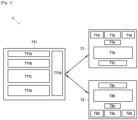
- FIG 1 schematically represents a modular and autonomous assembly 1 for detecting the angular position of the blades of a paddle wheel according to one embodiment of the invention, the detection assembly 1 being intended to be mounted on a turbomachine 10.
- the modular and autonomous detection assembly, or kit 1 comprises a main housing 711, a first sensor 71 and a second sensor 72.
- the assembly could comprise more than two sensors.
- the main housing 711 includes a communication unit 711a, a main power supply battery 711b, a storage unit 711c, two reversible manual fixing clips 711d and a main processing unit 711e.
- a part of the storage unit 711c is a RAM type random access memory dedicated to calculation and another part of the storage unit 711c is a NVRAM type read-only memory for storing results and configuration parameters of the main processing unit 711e such as a processor.
- the reversible manual fixing clips allow the main housing 711 to be fixed to a turbomachine 10 without the use of tools and in an easily removable manner.
- the fixing clips 711d are multi-point physical fixings for mechanical connection to a turbomachine 10.
- Each sensor 71 and 72 comprises a detection module, respectively denoted 71a and 72a, such as a Tip-timing sensor of the capacitive, optical, inductive, or pressure type for example, a local battery, respectively denoted 71b and 72b, a communication module, respectively denoted 71c and 72c, making it possible to communicate with the communication unit 711a of the main housing 71, two reversible manual fixing clips, respectively denoted 71d and 72d, and a local processing unit, respectively denoted 71e and 72e, such as a processor.
- a detection module respectively denoted 71a and 72a
- a local battery respectively denoted 71b and 72b
- a communication module respectively denoted 71c and 72c, making it possible to communicate with the communication unit 711a of the main housing 71
- two reversible manual fixing clips respectively denoted 71d
- the reversible manual fixing clips 71d or 72d allow the sensor 71 or 72 to be fixed to a turbomachine 10 without using a tool and in an easily removable manner.
- the fixing clips 71d or 72d are multi-point physical fixings for mechanical connection to a turbomachine 10.
- the information captured by the detection module 71a or 72a of the sensor 71 or 72 is delivered to the local processing unit 71e or 72e which prepares the signal before its transmission by the communication module 71c or 72c to the communication unit 711a of the main housing 711.
- the local processor 71e or 72e is capable of transforming the raw information acquired at several tens of kHz from the detection module 71a or 72a into a transmissible signal (digitization, compression, preprocessing, detection of passage of dawn).
- the communication module 71c or 72c of the sensors 71 and 72 is adapted to wirelessly transmit and receive information
- the communication unit 711a of the main housing 711 is configured and adapted to receive the information transmitted via a wireless communication network.
- the detection assembly 1 may comprise a single power source, such as a battery, located in the main housing 711 and supplying electrical energy to the sensors 71 and 72 via a wired connection.
- a single power source such as a battery
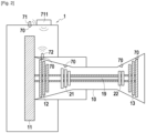
- turbomachine 10 On the figure 2 is schematically illustrated a turbomachine 10 according to an embodiment of the invention on which is mounted the modular and autonomous assembly for detecting the angular position of the blades of a bladed wheel of the figure 1 .
- a detection kit 1 comprising only a first sensor 71 and a second sensor 72 is mounted on a turbomachine 10.
- the first sensor 71 is mounted on the nacelle of the turbomachine 10 opposite the fan 11 to enable it to monitor the health of the blades of the fan 11.
- the second sensor 72 is mounted on the nacelle of the turbomachine 10 opposite the blades 12 of the low-pressure compressor stage.
- the main housing 711 is mounted on the casing of the fan of the turbomachine 10 in a low-temperature zone.
- the first sensor 71 and the second sensor 72 are installed on the turbomachine in housings 70 provided for this purpose and provided with an access hatch from the nacelle allowing easy opening and closing of access to the housings to mount or dismount the sensors 71 and 72.
- the main housing 711 may also be housed in a location provided for this purpose with a dedicated access hatch.
- the access hatch may also be communalized with a housing dedicated to receiving another element of the turbomachine, such as an oil access hatch.
- the turbomachine 10 comprises three other locations 70 provided to receive sensors similar to the first and second sensors 71 and 72.
- the first and second of the three other 70 locations which are free on the figure 2 , are located at the rear of the turbomachine 10, for one, opposite stage 13 of the low-pressure turbine and, for the other, opposite stage 22 of the high-pressure turbine.
- the third of the three other free locations 70 is located on the nacelle of the turbomachine 10 opposite stage 21 of the high-pressure compressor.
- FIG 3 schematically illustrates an assembly 20 for detecting damage to moving blades of a bladed wheel 11, or impeller, of an aircraft turbomachine 10 having a first configuration.
- the damage detection kit 20 includes the kit 1 for detecting the position of the blades of a bladed wheel of the figure 1 and means of alerts 9.
- Kit 1 does include all the elements described on the figure 1 , namely, a main housing 711 comprising in particular the main processing unit 711e and a storage unit 711c in the form of one or more databases D1, D2, a first sensor 71 and a second sensor 72.
- the first sensor 71 and the second sensor 72 of the blade position detection assembly 1 also form data acquisition means 7 of the damage detection assembly 20.
- the main processing unit 711e comprises additional means for performing damage detection.
- the main processing unit is thus configured to execute a computer program comprising code instructions designed to implement an acquisition, signal processing, analysis, and alert algorithm according to the damage detection method of the invention.
- the acquisition means 7 are configured to acquire a time signal S 1 relating to moving blades 111 to 115 of a bladed wheel 11, for example the bladed wheel of the fan (Fan) or of any other bladed wheel of the engine 10.
- the acquisition means 7 use a “tip-timing” technique to measure the times/instants of passage TOA (“Time Of Arrival”) of the moving blades 111 to 115.
- a tip-timing sensor 71 detects and counts the passages of the tips of the blades 111 to 115 relative to a time base.
- a tip-timing sensor 71 can measure the current passage time between the blades 111 to 115 relative to a reference point, also called “top-turn”.
- the passage times (TOA) specific to each blade 111 to 115 can then be deduced from the data measured by the main processing unit 711e, here via a calculation module 713 internal to the main processing unit 711e.
- a tip-timing sensor 71 makes it possible to acquire measurements relating to the times/instants of passage of the tip of each blade 111 to 115 movable in line with a reference zone of the bladed wheel 11. Furthermore, in the case where several sensors 71 are used on the same bladed wheel, it is possible, in order to limit the risks of loss of the tip-timing sensors 71, to position the sensors 71 so as to maximize their azimuthal distance, in order to distance them as far as possible from each other. Thus, in the event of a local failure of a sensor 71 (e.g.: impact of debris on a blade 111, fouling of a sensor 71), the risk that all of the sensors 71 are affected is minimized.
- a local failure of a sensor 71 e.g.: impact of debris on a blade 111, fouling of a sensor 71
- the blades 111 to 115 will pass in front of the same tip-timing sensor 71 in a regular manner. At a given speed, we will therefore measure, for a sensor 71, a time interval ⁇ t between the passage of two consecutive blades.
- the alteration of the state of a blade due for example to wear or to the ingestion of a foreign body FOD (“Foreign Object Damage”), can result in a modification of the position of the blade at the moment when it passes in front of at least one of the sensors 71.
- the main processing unit 711e is configured to analyze the different time signals S 1 with respect to an angular reference.
- the angular reference is provided, in this embodiment, by the kit 1 for detecting a “top-turn” of the figure 1 , which notably makes it possible to avoid using a tone wheel.
- the assembly 1 for detecting a “top-turn” is configured to detect the relative angular position of the blades of a first bladed wheel, such as the bladed wheel 11 of the fan, the damage to the blades of which is monitored using the first sensor 71, and of a second bladed wheel 12, the first and second bladed wheels 11 and 12 being crossed by the same air flow and, in the embodiment illustrated in the figure 3 , driven by the same shaft 19 of the turbomachine 10.
- Damage to the blades of the second impeller 12 can also be monitored in the same manner as for the first impeller 11 using other tip-timing sensors mounted opposite the second impeller 12, such as the second sensor 72.
- the first wheel 11 comprises a first number of blades N 1 and the second wheel 12 comprises a second number of blades N 2 , the first number of blades N 1 of the first bladed wheel 11 and the second number of blades N 2 of the second bladed wheel 12 being distinct and having no common divisor.
- the first and second numbers of blades N 1 and N 2 are therefore prime to each other.
- the blades are distributed regularly on each of the bladed wheels 11 and 12. Thus, on the same bladed wheel 11 or 12 two adjacent blades are separated by the same angular interval.
- the first and second sensors 71 and 72 are time-synchronized to the same clock and are configured to generate a signal each time a blade of the first or second impeller 11 or 12 passes in front of the corresponding sensor 71 or 72.
- the main processing unit 711e of the detection kit 1 is configured to determine the time interval separating the detection of a blade of the first blade wheel 11 with the detection of each of the blades of the second blade wheel 12.
- the first on-board sensor 71 returns a first time signal S 1 each time a blade of the first impeller 11 passes in front.
- the second on-board sensor 72 returns a second time signal S 2 each time a blade of the second impeller 12 passes in front.
- the time interval between each detection, ⁇ T1 for the first impeller 11 and ⁇ T2 for the second impeller blades 12, depends on the rotational speed of the shaft 19 and the respective number of blades on the impeller 11 or 12.
- FIG. 4 schematically illustrates an assembly 20 for detecting damage to moving blades of a bladed wheel 11 of an aircraft turbomachine 10 having a second configuration.
- the second configuration of the turbomachine 10 illustrated in the figure 4 differs from the first configuration of the turbomachine 10 illustrated in the figure 3 in that the first and second bladed wheels 11 and 12 are each traversed by an air flow which may not be the same and are driven by two separate shafts 190 and 195 connected to each other by a reducer 198.
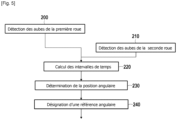
- FIG. 5 a flowchart of a method for detecting the angular position of the blades of a bladed wheel of a turbomachine according to an embodiment of the invention is presented.
- the assembly 1 for detecting a top turn can implement this method to detect the top turn.
- the method comprises a first step 200 in which the first sensor 71 detects the passage of each blade 111 to 115 of the first impeller 11.
- the second sensor 72 detects the passage of each blade 121 to 127 of the second wheel 12.
- the first and second sensors will therefore not have the same number of blade passage detections in the same shaft revolution.
- blades are not necessarily initially in view of the sensor, which introduces a delay before the first detection.
- the main processing unit 711e calculates the time interval ⁇ t separating the passage of a blade of the first blade 11 from each of the blades 121 to 127 of the second wheel 12.
- the values of the matrix correspond to the difference between the arrival time arrival time of the blades 111 to 115 of the first impeller 11 with the arrival time of the blades 121 to 127 of the second impeller 12, that is to say to the time intervals noted ⁇ T.
- the calculation of the time interval ⁇ T can take into account the reduction coefficient of the, if present, reduction device 198.
- the two paddle wheels 11 and 12 are not located on the same shaft but driven by two separate shafts 190 and 195 coupled together via a reduction device 198 with a reducing factor C.
- ⁇ t 1 60 2 ⁇ ⁇ C r e ductor ⁇ RPM ⁇ 1 N 1
- the matrix table thus provides as many angular references as desired. As indicated in the matrix table, the blades from one impeller to the other are not necessarily aligned either. If two impellers are aligned so that one blade from each aligned impeller is aligned together, we would have a cell in the table for which the difference would be zero.
- the calculation of the time interval ⁇ T may be normalized with respect to the rotational speed of the shaft 19 driving the two impellers 11 and 12 so that the calculation is independent of the rotational speed.
- the main processing unit 711e determines the relative angular position of each blade 111 to 115 of the first blade 11 with respect to the angular position of the blades 121 to 127 of the second wheel 12 from the values of the intervals ⁇ T and the value of the speed of the first and second bladed wheels 11 and 12.
- the offset is only related to the assembly of the impellers 11 and 12 on the shaft 19 and their relative alignment.
- This offset is characteristic of the turbomachine 10, and the resulting alignment between the blades from one blade wheel to the other is inherent to the turbomachine 10.
- This alignment is presented here relative to the passage time of the blades with respect to a Tip Timing sensor, which is ultimately the time signature of this alignment of the blades.
- the main processing unit 711e designates as angular reference, i.e. as top-turn, the blade of the first bladed wheel 11 having the smallest time difference ⁇ t with a blade of the second bladed wheel 12.
- the fifth blade 115 of the first impeller 11 and the seventh blade 127 of the second impeller 12 are the most aligned.
- This alignment feature allows to decide arbitrarily, that the fifth blade 115 of the first impeller 11 will be considered as the Top Tour, i.e. as the angular reference.
- Another blade of the first impeller 11 could have been arbitrarily designated as the top tour based on the analysis of the matrix table above.
- the alignment of the blades from one impeller to the other remains identical, as it is linked to the assembly, and to the number of respective blades of the impellers.
- the identification of the top-turn only requires one turn to be identified by the deployed algorithm.
- the first revolution of the engine 10 makes it possible to reconstruct the Top-Tour. Then each detection of the blade chosen as the top-tour will give the time reference, in the sense of tip-timing, and angular reference of the top-tour.
- the system 20 for detecting damage to a blade seeks to detect a lasting degradation in the performance of one or more blades 111 to 115 linked to damage, and not a simple temporary disturbance observable on the signal S1.
- the angular reference (top turn T12) described above is only used to identify each of the blades 111 to 115 relative to the others.
- the detection of damage to a blade which will be described later, therefore does not consist here in the simple observation or detection of the variation of the interval ⁇ t between the pulses measured between the blades 111 by each tip-timing sensor 71.
- At least one tip-timing sensor 71 may be used to measure the speed of the aircraft engine 10.
- Each tip-timing sensor 71 can be of the capacitive, inductive, eddy current type, or even an optical probe, these different types of sensors being robust, precise and space-saving.
- this method comprises a step E1 of measuring the speed of the engine 10 carried out by the acquisition means 7.
- the measurement of the speed of the engine 10 can be carried out by a tip-timing sensor 71.
- the tip-timing sensor 71 or 72 of a blade wheel 11 or 12 performs measurements relating to the times/instants of passage of the tip of each moving blade in line with the sensor.
- the processing means 11 then perform a conditioning of the measurements from the tip-timing sensor 71 or 72.
- This conditioning consists of identifying in real time each blade in the measured time signal using an angular reference, extracting from the temporary signal the passage time (TOA) relating to an identified blade, associating with the identified blade its extracted passage time as well as information relating to its revolution number (step E2).
- the main processing unit 711e calculates, via the calculation module 713, a deflection at tip of this blade (step E3), that is to say the spatial deviation of the tip of the blade 111 relative to a theoretical position of the latter at rest.
- the main processing unit 711e extracts, via an extraction module 712 illustrated in the figure 3 , the dynamic component for each calculated deflection, i.e. the isolate from the static component.
- the extraction of the dynamic component is carried out using isolation methods known from the state of the art (e.g. averaging, or using a high-pass filter to extract a high-frequency component).
- the main processing unit 711e further performs, via a selection module 714, a selection step S of one or more speed ranges of the engine 10 for which all of the blades of the bladed wheel 11 are assumed to be synchronous, i.e. assumed to exhibit the same vibration behavior for the same speed range of the engine 10.
- the speed ranges of the engine 10 are here pre-identified with respect to a reference database, for example the database D1, as guaranteeing that all of the blades exhibit the same vibration behavior when they pass by the tip-timing sensor 71 or 72.
- the processing means 11 further comprise a processing module 715 taking as inputs the dynamic components selected by the selection module 714.
- the processing module 715 is configured to determine (step E5) a possible variation in the dynamic behavior of each blade, by determining a variation in the dynamic components of each blade, and by relating these variations to a reference database.
- the results of the determination step E5 are further added to the tracking database, here the database D2.
- the determination step E5 can be seen as a step of analyzing the dynamic vibration behavior of each blade for each engine speed range selected during the selection step S.
- the main processing unit 711e then proceeds, via a comparator 716, to a comparison step E6 following the determination step E5.
- the step of comparison E6 consists of comparing each detected variation of a dynamic component of the deflection of a blade 111, that is to say each variation of its dynamic behavior, with one or more thresholds pre-recorded in the reference database D1.
- each variation of dynamic component, therefore of dynamic behavior, detected for a blade 111 is notably compared to a first variation threshold, which indirectly corresponds to a state of health of the blade.
- This first threshold is linked to a second threshold which concerns the variation of the natural frequency of the blade 111, the reaching of this threshold corresponding to damage to the blade 111.
- the first and second thresholds were determined and then recorded in the D1 reference database during an initial E9 learning phase.
- the detection of a variation in the dynamic component of the deflection of the blade 111 is therefore here linked to the indirect detection of a drift in the natural frequency of this blade 111, this drift beyond a predetermined threshold reflecting damage to the latter.
- the variation in the dynamic component of the deflection/dynamic behavior of the blade 111 is greater than the first variation threshold, this means that the natural frequency of the blade 111 itself exhibits a drift reflecting damage to the blade 111. Indeed, damage to the blade 111 leads to a drift in its natural frequency and therefore to a drift in the dynamic component of its deflection.
- the blade 111 is identified (step E7) as damaged.
- An alarm indicating damage to the blade 111 is then emitted (step E8) to the alert means 9 (via, for example, sound and/or visualization means). Similarly, messages to be sent or made available for maintenance can be triggered during the emitting of the alarm.
Landscapes
- Engineering & Computer Science (AREA)
- Mechanical Engineering (AREA)
- General Engineering & Computer Science (AREA)
- Physics & Mathematics (AREA)
- General Physics & Mathematics (AREA)
- Aviation & Aerospace Engineering (AREA)
- Chemical & Material Sciences (AREA)
- Combustion & Propulsion (AREA)
- Structures Of Non-Positive Displacement Pumps (AREA)
- Testing Of Devices, Machine Parts, Or Other Structures Thereof (AREA)
- Length Measuring Devices With Unspecified Measuring Means (AREA)
- Turbine Rotor Nozzle Sealing (AREA)
Claims (10)
- Modulare und autonome Anordnung (1) zur Erfassung der Winkelposition von Schaufeln einer Turbomaschine (1), wobei die modulare Anordnung (1) dazu ausgestaltet ist, abnehmbar an einer Turbomaschine (10) montiert zu sein, die ein erstes Schaufelrad (11), das mit einer ersten Anzahl von Schaufeln (111 bis 115) ausgestattet ist, und ein zweites Schaufelrad (12) umfasst, das mit einer zweiten Anzahl von Schaufeln (121 bis 127) ausgestattet ist, wobei die zwei Schaufelräder (11, 12) jeweils von einem Luftstrom durchquert werden und direkt oder indirekt aneinander gekoppelt sind, und die erste Anzahl von Schaufeln des ersten Rades (11) und die zweite Anzahl von Schaufeln des zweiten Rades (12) verschieden und zueinander prim sind,und die Anordnung (1) umfasst:- mindestens eine elektrische Versorgungsquelle (711b, 71b, 72b), die den Betrieb von Elementen der Erfassungsanordnung (1) unabhängig von der Turbomaschine (10) erlaubt, auf welcher sie mitgeführt werden soll,- mindestens einen ersten Sensor (71), der dazu ausgestaltet ist, mit dem ersten Schaufelrad (11) der Turbomaschine (10) assoziiert zu sein,- mindestens einen zweiten Sensor (72), der dazu ausgestaltet ist, mit dem zweiten Schaufelrad (12) der Turbomaschine (10) assoziiert zu sein,- und ein Hauptgehäuse (711), das eine Hauptverarbeitungseinheit (711e) und Speichermittel (711c) beinhaltet,wobei die Sensoren (71, 72) jeweils dazu ausgestaltet sind, ein Signal (S1, S2) an jedem Durchgang einer Schaufel eines Schaufelrades vor dem Sensor zu erzeugen, und die Hauptverarbeitungseinheit (711e) dazu ausgestaltet ist, das Zeitintervall zu bestimmen, das die Erfassung einer Schaufel (111 bis 115) des ersten Rades (11) von der Erfassung jeder der Schaufeln (121 bis 127) des zweiten Rades (12) trennt.
- Modulare und autonome Erfassungsanordnung (1) nach Anspruch 1, wobei das Hauptgehäuse (711), der mindestens eine erste Sensor (71) und der mindestens eine zweite Sensor (72) jeweils Mittel (711d, 71d, 72d) zur reversiblen manuellen Befestigung umfassen, die zulassen, dass sie an der Turbomaschine (10) abnehmbar montiert werden.
- Modulare und autonome Erfassungsanordnung (1) nach einem der Ansprüche 1 oder 2, wobei jeder erste und zweite Sensor (71, 72) ein Erfassungsmodul (71a, 72a), ein lokales Verarbeitungsmodul (71e, 72e) und Kommunikationsmittel (71c, 72c) umfasst, die dazu ausgestaltet sind, die Messungen des entsprechenden Sensors (71, 72) an die Verarbeitungseinheit (711e) zu liefern.
- Modulare und autonome Erfassungsanordnung (1) nach Anspruch 3, wobei jeder erste und zweite Sensor ferner eine Versorgungsquelle (71b) des Sensors umfassen und die Kommunikationsmittel drahtlose Kommunikationsmittel sind.
- Modulare und autonome Erfassungsanordnung (1) nach einem der Ansprüche 1 bis 4, wobei das Hauptgehäuse (711) ferner ein Taktgebermodul umfasst, auf welchem der mindestens eine erste und mindestens eine zweite Sensor (71, 72) synchronisiert sind.
- Anordnung (20) zur Erfassung von Schäden einer Schaufel eines Schaufelrades einer Turbomaschine, umfassend eine modulare und autonome Anordnung (1) zur Erfassung der Winkelposition von Schaufeln eines Schaufelrades nach einem der Ansprüche 1 bis 5, und Warnungsmittel (9).
- Turbomaschine (10), umfassend eine autonome und modulare Anordnung (1) zur Erfassung der Winkelposition von Schaufeln eines Schaufelrades nach einem der Ansprüche 1 bis 6 oder eine Anordnung (20) zur Erfassung von Schäden einer Schaufel eines Schaufelrades einer Turbomaschine nach Anspruch 6, wobei die Turbomaschine (10) für jedes Element der Anordnung (1) von dem Hauptgehäuse (711), dem mindestens ersten Sensor (71) und dem mindestens zweiten Sensor (72) eine Aufnahme (70) und eine Zugangsklappe zu der Aufnahme (70) umfasst.
- Turbomaschine (10) nach Anspruch 7, umfassend ein erstes Schaufelrad (11), das eine erste Anzahl von Schaufeln (111 bis 115) umfasst, und ein zweites Schaufelrad (12), das eine zweite Anzahl von Schaufeln (121 bis 127) umfasst, wobei die zwei Schaufelräder (11, 12) jeweils von einem Luftstrom durchquert werden und direkt oder indirekt aneinander gekoppelt sind, und die erste Anzahl von Schaufeln des ersten Rades (11) und die zweite Anzahl von Schaufeln des zweiten Rades (12) verschieden und zueinander prim sind.
- Turbomaschine (10) nach Anspruch 8, wobei der mindestens eine erste und mindestens eine zweite Sensor (71, 72) eine Frequenzbandbreite besitzen, die den Drehzahlen der Welle entspricht, für welche die Schaufeln erfasst werden.
- Luftfahrzeug, umfassend mindestens eine Turbomaschine (10) nach einem der Ansprüche 7 bis 9.
Applications Claiming Priority (2)
| Application Number | Priority Date | Filing Date | Title |
|---|---|---|---|
| FR1912726A FR3103212B1 (fr) | 2019-11-14 | 2019-11-14 | Ensemble modulaire et autonome de détection de la position angulaire des aubes d’une roue à aubes et ensemble modulaire et autonome de détection d’endommagement des aubes d’une roue à aubes d’une turbomachine |
| PCT/FR2020/052085 WO2021094700A1 (fr) | 2019-11-14 | 2020-11-13 | Ensemble modulaire et autonome de detection de la position angulaire des aubes d'une roue a aubes et ensemble modulaire et autonome de detection d'endommagement des aubes d'une roue a aubes d'une turbomachine |
Publications (2)
| Publication Number | Publication Date |
|---|---|
| EP4058758A1 EP4058758A1 (de) | 2022-09-21 |
| EP4058758B1 true EP4058758B1 (de) | 2024-11-06 |
Family
ID=69811037
Family Applications (1)
| Application Number | Title | Priority Date | Filing Date |
|---|---|---|---|
| EP20823894.9A Active EP4058758B1 (de) | 2019-11-14 | 2020-11-13 | Modulare und autonome anordnung zur erfassung der winkelposition der schaufeln eines laufrades und modulare und autonome anordnung zum erkennen von schäden an den schaufeln eines laufrades eines turbinenmotors |
Country Status (5)
| Country | Link |
|---|---|
| US (1) | US11994033B2 (de) |
| EP (1) | EP4058758B1 (de) |
| CN (1) | CN114867994B (de) |
| FR (1) | FR3103212B1 (de) |
| WO (1) | WO2021094700A1 (de) |
Families Citing this family (7)
| Publication number | Priority date | Publication date | Assignee | Title |
|---|---|---|---|---|
| FR3103273B1 (fr) * | 2019-11-14 | 2022-01-28 | Safran Aircraft Engines | Procédé de surveillance de la torsion d’un arbre rotatif sur une turbomachine d’un aéronef |
| CN113865876B (zh) * | 2021-08-24 | 2023-11-24 | 东南大学 | 一种高温环境中涡轮的检测系统 |
| CN118677557B (zh) * | 2023-03-20 | 2026-05-01 | 上海交通大学 | 一种用于叶尖定时采集系统的时钟同步装置 |
| CN116182761B (zh) * | 2023-04-18 | 2023-07-04 | 广东机电职业技术学院 | 一种发动机涡轮盘接叶偏差检测方法及系统 |
| EP4506244A1 (de) * | 2023-08-09 | 2025-02-12 | Ratier-Figeac SAS | Schutzsystem |
| US20250179931A1 (en) * | 2023-12-01 | 2025-06-05 | Rtx Corporation | Once per revolution signal optical inspection system |
| FR3160434A1 (fr) * | 2024-03-20 | 2025-09-26 | Safran Aircraft Engines | Turbomachine d’aeronef |
Family Cites Families (19)
| Publication number | Priority date | Publication date | Assignee | Title |
|---|---|---|---|---|
| IN171306B (de) * | 1988-02-04 | 1992-09-12 | Westinghouse Electric Corp | |
| US4948337A (en) * | 1989-05-01 | 1990-08-14 | United Technologies Corporation | Aircraft engine propulsor blade pitch sensing |
| ES2547539T5 (es) * | 2008-05-30 | 2021-11-26 | Vestas Wind Sys As | Un rotor de turbina eólica, una turbina eólica y uso de los mismos |
| US8111161B2 (en) * | 2009-02-27 | 2012-02-07 | General Electric Company | Methods, systems and/or apparatus relating to turbine blade monitoring |
| FR2945628B1 (fr) * | 2009-05-18 | 2011-06-10 | Airbus France | Dispositif de reglage de l'angle de calage des pales d'helice pour une maquette de moteur. |
| FR2949220B1 (fr) | 2009-08-21 | 2011-09-09 | Snecma | Procede et systeme de detection de l'ingestion d'un objet par un turboreacteur d'avion au cours d'une mission |
| US8515711B2 (en) * | 2010-10-21 | 2013-08-20 | Siemens Energy, Inc. | Diagnostic system and method for monitoring operating conditions of components of a turbine machine |
| FR2968038B1 (fr) | 2010-11-26 | 2012-12-28 | Snecma | Systeme de detection d'un evenement fugace sur une roue aubagee de moteur d'aeronef |
| FR2970291B1 (fr) | 2011-01-07 | 2013-02-08 | Turbomeca | Dispositif et procede de surveillance de rotor |
| US10012072B2 (en) * | 2012-03-22 | 2018-07-03 | Exxonmobil Upstream Research Company | Multi-phase flow meter and methods for use thereof |
| GB2528882A (en) * | 2014-08-01 | 2016-02-10 | Bae Systems Plc | Turbine blade monitoring |
| FR3030625B1 (fr) * | 2014-12-18 | 2019-10-25 | Safran Aircraft Engines | Procede et dispositif de determination de la vibration de pieces rotatives de turbomachine |
| CN109313069B (zh) * | 2016-04-26 | 2021-08-03 | 比勒陀利亚大学 | 一种使用叶尖定时(btt)监测涡轮机转子叶片的方法和系统 |
| WO2018002818A1 (en) * | 2016-06-27 | 2018-01-04 | University Of Pretoria | A method and system for monitoring rotor blades of a turbomachine using blade tip timing (btt) |
| US10316689B2 (en) * | 2016-08-22 | 2019-06-11 | Rolls-Royce Corporation | Gas turbine engine health monitoring system with shaft-twist sensors |
| EP3354561A1 (de) * | 2017-01-30 | 2018-08-01 | Ge Avio S.r.l. | System und verfahren zur lokalisierung der segelwinkelstellung von propellerblättern |
| US10775269B2 (en) * | 2017-02-08 | 2020-09-15 | Raytheon Technologies Corporation | Blade health inspection using an excitation actuator and vibration sensor |
| FR3075353B1 (fr) * | 2017-12-14 | 2020-05-29 | Safran Aircraft Engines | Mesure non intrusive du calage d'une pale |
| FR3077882B1 (fr) * | 2018-02-12 | 2020-09-04 | Safran Aircraft Engines | Procede et systeme de detection d'un endommagement d'aubes mobiles d'un aeronef |
-
2019
- 2019-11-14 FR FR1912726A patent/FR3103212B1/fr active Active
-
2020
- 2020-11-13 EP EP20823894.9A patent/EP4058758B1/de active Active
- 2020-11-13 CN CN202080086266.6A patent/CN114867994B/zh active Active
- 2020-11-13 US US17/755,995 patent/US11994033B2/en active Active
- 2020-11-13 WO PCT/FR2020/052085 patent/WO2021094700A1/fr not_active Ceased
Also Published As
| Publication number | Publication date |
|---|---|
| US20220403752A1 (en) | 2022-12-22 |
| WO2021094700A1 (fr) | 2021-05-20 |
| CN114867994B (zh) | 2025-09-12 |
| FR3103212A1 (fr) | 2021-05-21 |
| FR3103212B1 (fr) | 2022-04-01 |
| US11994033B2 (en) | 2024-05-28 |
| CN114867994A (zh) | 2022-08-05 |
| EP4058758A1 (de) | 2022-09-21 |
Similar Documents
| Publication | Publication Date | Title |
|---|---|---|
| FR3103212A1 (fr) | Ensemble modulaire et autonome de détection de la position angulaire des aubes d’une roue à aubes et ensemble modulaire et autonome de détection d’endommagement des aubes d’une roue à aubes d’une turbomachine | |
| CA2779256C (fr) | Procede de detection d'un endommagement d'au moins un roulement de palier d'un moteur | |
| FR2919661A1 (fr) | Systeme et procede de detection d'un decalage de l'excentricite de base d'un rotor | |
| EP4058772B1 (de) | Verfahren zur überwachung der torsion einer rotierenden welle an einer turbomaschine eines flugzeugs | |
| EP2828486A1 (de) | Erkennung und verfolgung von schäden oder auswirkungen eines fremdkörpers auf einen flugzeugmotorlüfter | |
| CA2964815C (fr) | Procede et dispositif de surveillance d'une roue aubagee de moteur d'aeronef par mesure de position d'equilibre | |
| FR2968038A1 (fr) | Systeme de detection d'un evenement fugace sur une roue aubagee de moteur d'aeronef | |
| FR2986269A1 (fr) | Systeme de detection d'un impact sur une roue aubagee de moteur d'aeronef | |
| FR2551209A1 (fr) | Procede et appareil de mesure de desequilibre | |
| EP3752811B1 (de) | Verfahren und system zur erkennung von schäden an den beweglichen schaufeln eines flugzeuges | |
| EP3378790B1 (de) | Abdeckung einer strömungsmaschine mit bildschirm | |
| FR2966597A1 (fr) | Procede de surveillance d’un element tournant appartenant a une transmission mecanique d’un aerogenerateur | |
| FR2988130A1 (fr) | Systeme de detection de defaut sur une roue aubagee de moteur d'aeronef | |
| FR2956206A1 (fr) | Stimulateur vibratoire pour le controle d'une aube d'une roue aubagee d'une turbomachine | |
| EP3578929B1 (de) | Verfahren und system zur bestimmung der winkelposition der laufradschaufeln eines schaufelrads eines turbotriebwerks | |
| FR3035982A1 (fr) | Procede de surveillance d'un moteur d'aeronef en fonctionnement pendant un vol | |
| EP4070068B1 (de) | Verfahren zur überwachung einer turbomaschine, vorrichtung, system, flugzeug und computerprogrammprodukt | |
| CA2749849C (fr) | Procede et dispositif pour optimiser l'utilisation d'un moteur | |
| FR2986567A1 (fr) | Procede de surveillance d'un moteur et dispositif | |
| FR3071919B1 (fr) | Systeme et procede de mesure de decalage | |
| FR3077881A1 (fr) | Procede et systeme de detection d'un endommagement d'aubes mobiles d'un aeronef | |
| WO2023281183A1 (fr) | Procede, dispositif et systeme de surveillance d'une turbomachine | |
| FR3045727A1 (fr) | Procede et dispositif d'estimation de parametres de fonctionnement d'un moteur a turbine a gaz |
Legal Events
| Date | Code | Title | Description |
|---|---|---|---|
| STAA | Information on the status of an ep patent application or granted ep patent |
Free format text: STATUS: UNKNOWN |
|
| STAA | Information on the status of an ep patent application or granted ep patent |
Free format text: STATUS: THE INTERNATIONAL PUBLICATION HAS BEEN MADE |
|
| PUAI | Public reference made under article 153(3) epc to a published international application that has entered the european phase |
Free format text: ORIGINAL CODE: 0009012 |
|
| STAA | Information on the status of an ep patent application or granted ep patent |
Free format text: STATUS: REQUEST FOR EXAMINATION WAS MADE |
|
| 17P | Request for examination filed |
Effective date: 20220607 |
|
| AK | Designated contracting states |
Kind code of ref document: A1 Designated state(s): AL AT BE BG CH CY CZ DE DK EE ES FI FR GB GR HR HU IE IS IT LI LT LU LV MC MK MT NL NO PL PT RO RS SE SI SK SM TR |
|
| DAV | Request for validation of the european patent (deleted) | ||
| DAX | Request for extension of the european patent (deleted) | ||
| STAA | Information on the status of an ep patent application or granted ep patent |
Free format text: STATUS: EXAMINATION IS IN PROGRESS |
|
| 17Q | First examination report despatched |
Effective date: 20231115 |
|
| GRAP | Despatch of communication of intention to grant a patent |
Free format text: ORIGINAL CODE: EPIDOSNIGR1 |
|
| STAA | Information on the status of an ep patent application or granted ep patent |
Free format text: STATUS: GRANT OF PATENT IS INTENDED |
|
| INTG | Intention to grant announced |
Effective date: 20240624 |
|
| GRAS | Grant fee paid |
Free format text: ORIGINAL CODE: EPIDOSNIGR3 |
|
| GRAA | (expected) grant |
Free format text: ORIGINAL CODE: 0009210 |
|
| STAA | Information on the status of an ep patent application or granted ep patent |
Free format text: STATUS: THE PATENT HAS BEEN GRANTED |
|
| AK | Designated contracting states |
Kind code of ref document: B1 Designated state(s): AL AT BE BG CH CY CZ DE DK EE ES FI FR GB GR HR HU IE IS IT LI LT LU LV MC MK MT NL NO PL PT RO RS SE SI SK SM TR |
|
| REG | Reference to a national code |
Ref country code: GB Ref legal event code: FG4D Free format text: NOT ENGLISH |
|
| REG | Reference to a national code |
Ref country code: CH Ref legal event code: EP |
|
| REG | Reference to a national code |
Ref country code: DE Ref legal event code: R096 Ref document number: 602020040973 Country of ref document: DE |
|
| REG | Reference to a national code |
Ref country code: IE Ref legal event code: FG4D Free format text: LANGUAGE OF EP DOCUMENT: FRENCH |
|
| REG | Reference to a national code |
Ref country code: LT Ref legal event code: MG9D |
|
| REG | Reference to a national code |
Ref country code: NL Ref legal event code: MP Effective date: 20241106 |
|
| PG25 | Lapsed in a contracting state [announced via postgrant information from national office to epo] |
Ref country code: HR Free format text: LAPSE BECAUSE OF FAILURE TO SUBMIT A TRANSLATION OF THE DESCRIPTION OR TO PAY THE FEE WITHIN THE PRESCRIBED TIME-LIMIT Effective date: 20241106 Ref country code: IS Free format text: LAPSE BECAUSE OF FAILURE TO SUBMIT A TRANSLATION OF THE DESCRIPTION OR TO PAY THE FEE WITHIN THE PRESCRIBED TIME-LIMIT Effective date: 20250306 Ref country code: PT Free format text: LAPSE BECAUSE OF FAILURE TO SUBMIT A TRANSLATION OF THE DESCRIPTION OR TO PAY THE FEE WITHIN THE PRESCRIBED TIME-LIMIT Effective date: 20250306 |
|
| PG25 | Lapsed in a contracting state [announced via postgrant information from national office to epo] |
Ref country code: NL Free format text: LAPSE BECAUSE OF FAILURE TO SUBMIT A TRANSLATION OF THE DESCRIPTION OR TO PAY THE FEE WITHIN THE PRESCRIBED TIME-LIMIT Effective date: 20241106 Ref country code: FI Free format text: LAPSE BECAUSE OF FAILURE TO SUBMIT A TRANSLATION OF THE DESCRIPTION OR TO PAY THE FEE WITHIN THE PRESCRIBED TIME-LIMIT Effective date: 20241106 |
|
| REG | Reference to a national code |
Ref country code: AT Ref legal event code: MK05 Ref document number: 1739795 Country of ref document: AT Kind code of ref document: T Effective date: 20241106 |
|
| PG25 | Lapsed in a contracting state [announced via postgrant information from national office to epo] |
Ref country code: BG Free format text: LAPSE BECAUSE OF FAILURE TO SUBMIT A TRANSLATION OF THE DESCRIPTION OR TO PAY THE FEE WITHIN THE PRESCRIBED TIME-LIMIT Effective date: 20241106 |
|
| PG25 | Lapsed in a contracting state [announced via postgrant information from national office to epo] |
Ref country code: ES Free format text: LAPSE BECAUSE OF FAILURE TO SUBMIT A TRANSLATION OF THE DESCRIPTION OR TO PAY THE FEE WITHIN THE PRESCRIBED TIME-LIMIT Effective date: 20241106 |
|
| PG25 | Lapsed in a contracting state [announced via postgrant information from national office to epo] |
Ref country code: NO Free format text: LAPSE BECAUSE OF FAILURE TO SUBMIT A TRANSLATION OF THE DESCRIPTION OR TO PAY THE FEE WITHIN THE PRESCRIBED TIME-LIMIT Effective date: 20250206 |
|
| PG25 | Lapsed in a contracting state [announced via postgrant information from national office to epo] |
Ref country code: LV Free format text: LAPSE BECAUSE OF FAILURE TO SUBMIT A TRANSLATION OF THE DESCRIPTION OR TO PAY THE FEE WITHIN THE PRESCRIBED TIME-LIMIT Effective date: 20241106 Ref country code: GR Free format text: LAPSE BECAUSE OF FAILURE TO SUBMIT A TRANSLATION OF THE DESCRIPTION OR TO PAY THE FEE WITHIN THE PRESCRIBED TIME-LIMIT Effective date: 20250207 Ref country code: AT Free format text: LAPSE BECAUSE OF FAILURE TO SUBMIT A TRANSLATION OF THE DESCRIPTION OR TO PAY THE FEE WITHIN THE PRESCRIBED TIME-LIMIT Effective date: 20241106 |
|
| PG25 | Lapsed in a contracting state [announced via postgrant information from national office to epo] |
Ref country code: PL Free format text: LAPSE BECAUSE OF FAILURE TO SUBMIT A TRANSLATION OF THE DESCRIPTION OR TO PAY THE FEE WITHIN THE PRESCRIBED TIME-LIMIT Effective date: 20241106 |
|
| PG25 | Lapsed in a contracting state [announced via postgrant information from national office to epo] |
Ref country code: RS Free format text: LAPSE BECAUSE OF FAILURE TO SUBMIT A TRANSLATION OF THE DESCRIPTION OR TO PAY THE FEE WITHIN THE PRESCRIBED TIME-LIMIT Effective date: 20250206 |
|
| REG | Reference to a national code |
Ref country code: CH Ref legal event code: PL |
|
| PG25 | Lapsed in a contracting state [announced via postgrant information from national office to epo] |
Ref country code: SM Free format text: LAPSE BECAUSE OF FAILURE TO SUBMIT A TRANSLATION OF THE DESCRIPTION OR TO PAY THE FEE WITHIN THE PRESCRIBED TIME-LIMIT Effective date: 20241106 |
|
| PG25 | Lapsed in a contracting state [announced via postgrant information from national office to epo] |
Ref country code: DK Free format text: LAPSE BECAUSE OF FAILURE TO SUBMIT A TRANSLATION OF THE DESCRIPTION OR TO PAY THE FEE WITHIN THE PRESCRIBED TIME-LIMIT Effective date: 20241106 |
|
| PG25 | Lapsed in a contracting state [announced via postgrant information from national office to epo] |
Ref country code: LU Free format text: LAPSE BECAUSE OF NON-PAYMENT OF DUE FEES Effective date: 20241113 |
|
| REG | Reference to a national code |
Ref country code: CH Ref legal event code: PL |
|
| PG25 | Lapsed in a contracting state [announced via postgrant information from national office to epo] |
Ref country code: EE Free format text: LAPSE BECAUSE OF FAILURE TO SUBMIT A TRANSLATION OF THE DESCRIPTION OR TO PAY THE FEE WITHIN THE PRESCRIBED TIME-LIMIT Effective date: 20241106 |
|
| PG25 | Lapsed in a contracting state [announced via postgrant information from national office to epo] |
Ref country code: CH Free format text: LAPSE BECAUSE OF NON-PAYMENT OF DUE FEES Effective date: 20241130 |
|
| PG25 | Lapsed in a contracting state [announced via postgrant information from national office to epo] |
Ref country code: RO Free format text: LAPSE BECAUSE OF FAILURE TO SUBMIT A TRANSLATION OF THE DESCRIPTION OR TO PAY THE FEE WITHIN THE PRESCRIBED TIME-LIMIT Effective date: 20241106 |
|
| PG25 | Lapsed in a contracting state [announced via postgrant information from national office to epo] |
Ref country code: SK Free format text: LAPSE BECAUSE OF FAILURE TO SUBMIT A TRANSLATION OF THE DESCRIPTION OR TO PAY THE FEE WITHIN THE PRESCRIBED TIME-LIMIT Effective date: 20241106 |
|
| PG25 | Lapsed in a contracting state [announced via postgrant information from national office to epo] |
Ref country code: CZ Free format text: LAPSE BECAUSE OF FAILURE TO SUBMIT A TRANSLATION OF THE DESCRIPTION OR TO PAY THE FEE WITHIN THE PRESCRIBED TIME-LIMIT Effective date: 20241106 |
|
| PG25 | Lapsed in a contracting state [announced via postgrant information from national office to epo] |
Ref country code: IT Free format text: LAPSE BECAUSE OF FAILURE TO SUBMIT A TRANSLATION OF THE DESCRIPTION OR TO PAY THE FEE WITHIN THE PRESCRIBED TIME-LIMIT Effective date: 20241106 |
|
| REG | Reference to a national code |
Ref country code: DE Ref legal event code: R097 Ref document number: 602020040973 Country of ref document: DE |
|
| REG | Reference to a national code |
Ref country code: BE Ref legal event code: MM Effective date: 20241130 |
|
| PG25 | Lapsed in a contracting state [announced via postgrant information from national office to epo] |
Ref country code: SE Free format text: LAPSE BECAUSE OF FAILURE TO SUBMIT A TRANSLATION OF THE DESCRIPTION OR TO PAY THE FEE WITHIN THE PRESCRIBED TIME-LIMIT Effective date: 20241106 |
|
| PLBE | No opposition filed within time limit |
Free format text: ORIGINAL CODE: 0009261 |
|
| STAA | Information on the status of an ep patent application or granted ep patent |
Free format text: STATUS: NO OPPOSITION FILED WITHIN TIME LIMIT |
|
| PG25 | Lapsed in a contracting state [announced via postgrant information from national office to epo] |
Ref country code: MC Free format text: LAPSE BECAUSE OF FAILURE TO SUBMIT A TRANSLATION OF THE DESCRIPTION OR TO PAY THE FEE WITHIN THE PRESCRIBED TIME-LIMIT Effective date: 20241106 |
|
| 26N | No opposition filed |
Effective date: 20250807 |
|
| PG25 | Lapsed in a contracting state [announced via postgrant information from national office to epo] |
Ref country code: BE Free format text: LAPSE BECAUSE OF NON-PAYMENT OF DUE FEES Effective date: 20241130 |
|
| PG25 | Lapsed in a contracting state [announced via postgrant information from national office to epo] |
Ref country code: IE Free format text: LAPSE BECAUSE OF NON-PAYMENT OF DUE FEES Effective date: 20241113 |
|
| PGFP | Annual fee paid to national office [announced via postgrant information from national office to epo] |
Ref country code: DE Payment date: 20251118 Year of fee payment: 6 |
|
| PGFP | Annual fee paid to national office [announced via postgrant information from national office to epo] |
Ref country code: GB Payment date: 20251125 Year of fee payment: 6 |
|
| PGFP | Annual fee paid to national office [announced via postgrant information from national office to epo] |
Ref country code: FR Payment date: 20251125 Year of fee payment: 6 |
|
| PG25 | Lapsed in a contracting state [announced via postgrant information from national office to epo] |
Ref country code: HU Free format text: LAPSE BECAUSE OF FAILURE TO SUBMIT A TRANSLATION OF THE DESCRIPTION OR TO PAY THE FEE WITHIN THE PRESCRIBED TIME-LIMIT; INVALID AB INITIO Effective date: 20201113 |
|
| PG25 | Lapsed in a contracting state [announced via postgrant information from national office to epo] |
Ref country code: CY Free format text: LAPSE BECAUSE OF FAILURE TO SUBMIT A TRANSLATION OF THE DESCRIPTION OR TO PAY THE FEE WITHIN THE PRESCRIBED TIME-LIMIT; INVALID AB INITIO Effective date: 20201113 |