EP4057788A1 - A high availability fluid connector for liquid cooling - Google Patents
A high availability fluid connector for liquid cooling Download PDFInfo
- Publication number
- EP4057788A1 EP4057788A1 EP22159169.6A EP22159169A EP4057788A1 EP 4057788 A1 EP4057788 A1 EP 4057788A1 EP 22159169 A EP22159169 A EP 22159169A EP 4057788 A1 EP4057788 A1 EP 4057788A1
- Authority
- EP
- European Patent Office
- Prior art keywords
- elliptical
- fluid connectors
- server
- coolant
- frame
- Prior art date
- Legal status (The legal status is an assumption and is not a legal conclusion. Google has not performed a legal analysis and makes no representation as to the accuracy of the status listed.)
- Withdrawn
Links
Images



Classifications
-
- H—ELECTRICITY
- H05—ELECTRIC TECHNIQUES NOT OTHERWISE PROVIDED FOR
- H05K—PRINTED CIRCUITS; CASINGS OR CONSTRUCTIONAL DETAILS OF ELECTRIC APPARATUS; MANUFACTURE OF ASSEMBLAGES OF ELECTRICAL COMPONENTS
- H05K7/00—Constructional details common to different types of electric apparatus
- H05K7/20—Modifications to facilitate cooling, ventilating, or heating
- H05K7/20709—Modifications to facilitate cooling, ventilating, or heating for server racks or cabinets; for data centers, e.g. 19-inch computer racks
- H05K7/20763—Liquid cooling without phase change
- H05K7/20781—Liquid cooling without phase change within cabinets for removing heat from server blades
-
- G—PHYSICS
- G06—COMPUTING OR CALCULATING; COUNTING
- G06F—ELECTRIC DIGITAL DATA PROCESSING
- G06F1/00—Details not covered by groups G06F3/00 - G06F13/00 and G06F21/00
- G06F1/16—Constructional details or arrangements
- G06F1/20—Cooling means
-
- G—PHYSICS
- G06—COMPUTING OR CALCULATING; COUNTING
- G06F—ELECTRIC DIGITAL DATA PROCESSING
- G06F1/00—Details not covered by groups G06F3/00 - G06F13/00 and G06F21/00
- G06F1/16—Constructional details or arrangements
- G06F1/18—Packaging or power distribution
- G06F1/181—Enclosures
-
- H—ELECTRICITY
- H05—ELECTRIC TECHNIQUES NOT OTHERWISE PROVIDED FOR
- H05K—PRINTED CIRCUITS; CASINGS OR CONSTRUCTIONAL DETAILS OF ELECTRIC APPARATUS; MANUFACTURE OF ASSEMBLAGES OF ELECTRICAL COMPONENTS
- H05K7/00—Constructional details common to different types of electric apparatus
- H05K7/20—Modifications to facilitate cooling, ventilating, or heating
- H05K7/20218—Modifications to facilitate cooling, ventilating, or heating using a liquid coolant without phase change in electronic enclosures
- H05K7/20272—Accessories for moving fluid, for expanding fluid, for connecting fluid conduits, for distributing fluid, for removing gas or for preventing leakage, e.g. pumps, tanks or manifolds
Definitions
- Embodiments of the present invention relate generally to data center cooling. More particularly, embodiments of the invention relate to server racks, including installation and removal of server equipment that connects to a liquid cooling module.
- Cooling is a prominent factor in a computer system and data center design.
- the number of high performance electronics components such as high performance processors packaged inside servers has steadily increased, thereby increasing the amount of heat generated and dissipated during the ordinary operations of the servers.
- the reliability of servers used within a data center decreases if the environment in which they operate is permitted to increase in temperature over time. Maintaining a proper thermal environment is critical for normal operations of these servers in data centers, as well as the server performance and lifetime. It requires more effective and efficient cooling solutions especially in the cases of cooling these high performance servers.
- a server rack in a data center may contain servers and/or cooling distribution units having different types, sizes, gender, and location of liquid coolant connections.
- a coolant distribution unit couples to a coolant distribution manifold at the back of the server rack.
- Each server that requires liquid cooling will be connected to the coolant distribution manifold.
- the coolant distribution manifold often comprises a variety of interconnection hoses or a pair of distribution manifolds in the form of sealed square tubing with fluid connectors placed at fixed intervals along the tubing of the manifold.
- rack manifold designs for server rack equipment connection sizes, locations, connector types, or genders There are different types of rack manifold designs for server rack equipment connection sizes, locations, connector types, or genders. Servers and cooling distribution units in server racks require periodic service such that it is necessary to disconnect the liquid coolant connections at the back of the server rack to remove and service the server. Those connections are often deep in the back of the server rack and are not easily accessible.
- a blind mating adapter unit configured to fluidly couple a server in an electronic rack to one or more coolant distribution manifolds via blind mating.
- the blind mating adapter unit includes: an elliptical frame having an elliptical orbit about a center point of the elliptical frame configured to position a plurality of fluid connectors within the elliptical orbit; and an elliptical plate having a connector channel and a rotation axis, wherein the elliptical plate is configured to rotate about the rotation axis of the elliptical plate, wherein the plurality of fluid connectors are configured to traverse both the elliptical orbit of the elliptical frame and the connector channel of the elliptical plate, and wherein the blind mating adapter unit is configurable to fix an alignment of the plurality of fluid connectors to a plurality of mating fluid connectors on one or more coolant distribution manifolds in the electronic rack, such that when the server chassis is installed into the
- a server of an electronic rack includes: a cooling module comprising a coolant supply line, a heat transfer unit, and a coolant return line, wherein a first end of the coolant supply line and a first end of the coolant return line are coupled to the heat transfer unit; a blind mating adapter unit adjustably coupled to a chassis of the server, wherein the blind mating adapter unit includes: an elliptical frame having an elliptical orbit about a center point of the elliptical frame configured to position a plurality of fluid connectors within the elliptical orbit; an elliptical plate having a connector channel and a rotation axis, wherein the elliptical plate is configured to rotate about the rotation axis of the elliptical frame; wherein the plurality of fluid connectors and a second end of the coolant supply line and a second end of the coolant return line are configured to traverse both the elliptical orbit of the elliptical
- an electronic rack includes: one or more coolant distribution manifolds; and a plurality of servers arranged in a stack, wherein each server includes: a cooling module comprising a coolant supply line, a heat transfer unit, and a coolant return line, wherein a first end of the coolant supply line and a first end of the coolant return line are coupled to the heat transfer unit; a blind mating adapter unit adjustably coupled to a chassis of the server, wherein the blind mating adapter unit includes: an elliptical frame having an elliptical orbit about a center point of the elliptical frame configured to position a plurality of fluid connectors within the elliptical orbit; an elliptical plate having a connector channel and a rotation axis, wherein the elliptical plate is configured to rotate about the rotation axis of the elliptical frame; wherein the plurality of fluid connectors and a second end of the coolant supply line and a
- a blind mating adapter unit is configured to fluidly couple a server in an electronic rack (also termed "server rack") to a coolant distribution manifold via blind mating.
- Blind mating happens via a sliding or snapping action which can be accomplished without wrenches or other tools.
- Blind mating can include self-aligning features which allow a small misalignment when mating.
- the blind mating adapter unit can be installed onto the server chassis and configured for alignment before inserting the server into the server rack.
- the blind mating adapter unit can include an elliptical frame having an elliptical orbit about a center point of the elliptical frame, configured to position a plurality of fluid connectors within the elliptical orbit.
- the plurality of fluid connectors may be provided by coolant supply and return lines of a cooling module in the server.
- the blind mating adapter can also include an elliptical plate having a connector channel and a rotation axis.
- the elliptical plate is configured to rotate about the rotation axis of the elliptical frame.
- the plurality of fluid connectors are configured to traverse, or cross through, both the elliptical orbit of the elliptical frame and the connector channel of the elliptical plate.
- the blind mating adapter unit is configurable to fix an alignment of the plurality of fluid connectors to a plurality of mating fluid connectors on a coolant distribution manifold in the server rack. When the server chassis is installed into the server rack, the plurality of fluid connectors are blind mated to the mating plurality of fluid connectors on the coolant distribution manifold.
- the blind mating adapter unit further includes a mounting frame.
- the elliptical plate, elliptical frame, and rotation axis are adjustably coupled to a chassis of the server by the mounting frame.
- the mounting frame fixes the rotation axis of the elliptical plate at the center point of the elliptical frame.
- the fluid connectors of the blind mating adapter unit are rotatable within ⁇ 90° or ⁇ 180° about the rotation axis.
- the elliptical orbit comprises two elongated and parallel sides forming a pair of parallel channels. The fluid connectors can move within the elliptical orbit as the elliptical plate is rotated about the rotation axis.
- the elliptical orbit of the elliptical frame and the connector channel of the elliptical plate form a rotation path for the plurality of fluid connectors.
- the rotation axis can comprise a bearing assembly.
- the bearing assembly can include a plurality of predetermined detent positions at which the elliptical plate can be rotatably positioned with the rotation path.
- the blind mating adapter unit can further include a connector channel sleeve whose sides are perpendicular to the elliptical plate and substantially parallel a plurality of coolant lines traversing (crossing through) the elliptical frame and elliptical plate.
- a location of the blind mating adapter unit on the server chassis is adjustable, using the supporting frame, in a horizontal direction (x-axis) with respect to a direction facing into the electronic rack from the front or back of the electronic rack.
- a location of the plurality of fluid connectors can be adjusted in the vertical direction (y-axis). Adjustment in the vertical direction can be implemented by rotating the elliptical plate, by changing, or adjusting, a length of the mounting frame, or by adjusting a vertical location of the blind mating adapter unit using the supporting frame.
- a server can include a cooling module having a coolant supply line, a heat transfer unit, and a coolant return line.
- the server can further include a blind mating adapter unit having a plurality of fluid connectors that are adjustably configurable to blind mate to a corresponding plurality of mating fluid connectors on a coolant distribution manifold, as described in the first aspect, above.
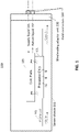
- FIG. 1 is a block diagram illustrating an example of a cooling module in a server chassis having a blind mating adapting unit, according to one embodiment.
- the cooling module 100 can include a processor/cold plate assembly that removes heat from processor chip 101.
- processor 101 is plugged onto a processor socket mounted on printed circuit board (PCB) or motherboard 102 coupled to other electrical components or circuits of a data processing system or server.
- PCB printed circuit board
- Processor 101 includes a cold plate 103 attached to it, which is coupled to a rack manifold that is coupled to liquid supply line 132 and/or liquid return line 131.
- the coupling of the cold plate 103 to the rack manifold, via coolant lines 131 and 132, can be via the blind mating adapter unit described herein.
- a portion of the heat generated by processor 101 is removed by the cooling liquid lines 131 and 132 via cold plate 103.
- the remaining portion of the heat enters into an air space underneath or above, which may be removed by an airflow generated by a cooling fan (not shown).
- a blind mating adapter unit 110 can be coupled to the server chassis 105 using a frame (not shown).
- the cold plate cooling liquid lines 131 and 132 can be coupled to the blind mating adapting unit 110 mounted to the frame on the server chassis to enable blind mating of the server's cooling lines to one or more coolant distribution manifolds in the server rack that house the server chassis 105.
- the liquid supply line 131 and liquid return line 132 can be hoses with either blind mating connectors.
- the cooling module 100 included in the server chassis 105 may be used in different types of servers and server racks.
- Blind mating adapter unit 110 can ensure proper mating and configuration for the fluid systems between the server rack and the cooling module(s) in the server.
- FIG. 2 illustrate plan view of an embodiment of a server 203 having a blind mating adapter unit, according to some embodiments.
- the blind mating adapter unit enables a piece of information technology (IT) equipment, such as a server 203, to be slid into the server rack 200 and blind mated to a portion of the fluid connectors on the coolant distribution manifolds 201 and 202 (collectively, 201/2) via the blind mating adapter unit.
- the fluid connectors 120 on the blind mating adapter unit are initially configured to align with corresponding fluid connectors on the coolant distribution manifolds 201/2.
- the server 203 can be repeatedly removed from the server rack and reinstalled by blind mating, without further adjustment.
- the blind mating adapter unit is installed into the server 203 chassis and configured for alignment before inserting the server 203 into the server rack.
- the blind mating adapter unit enables blind mating to fluid connectors on server rack coolant distribution manifolds for different cooling modules in a server chassis and different rack designs.
- a server 203 that has a cooling module (not shown) included within the server 203 as described above, with reference to Figure 1 .
- the cooling module is described above with reference to Figure 1 .
- the cooling module within the server 203 may include one or more hoses, tubes, or piping such as for a coolant supply line 131 and a coolant return line 132, or other coolant line.
- the coolant lines can be fluidly coupled at one end to the cooling module (not shown) in the server 203.
- the other end of each of the coolant supply 131 and coolant return lines 132 can be adjustably coupled to the blind mating adapter unit, as described herein and with reference to Figures 3-9 .
- the coolant lines 131 and 132 can also include fluid connectors 120 on their ends.
- a blind mating adapter unit can align a plurality of fluid connectors 120 on a plurality of coolant lines 131 and 132 that traverse an elliptical frame 330 and an elliptical plate 340.
- An elliptical orbit of elliptical plate 330 and a connector channel or elliptical plate 340 form a rotation path within which fluid connectors 120 and coolant hoses 131 and 132 can rotate about a rotation axis (not shown).
- the elliptical frame 330, elliptical plate 340, and rotation axis can be assembled to a mounting frame 310 that is coupled to a chassis of server 203 such that the fluid connectors 120 and associated coolant lines 131 and 132 can be rotatably adjusted within the rotation path.
- the fluid connectors 120 are rotated to align with corresponding mating fluid connectors 212 on coolant distribution manifolds 201/2.
- the server 203 can be removed and reinstalled into the server rack, by blind mating, without further adjustment.
- the blind mating adapter unit can be adjustably mounted to the chassis of the server 203 using mounting frame 310 and supporting frame 302.
- the mounting frame 310 of the blind mating adapter unit is adjustably coupled to the supporting frame 302 to facilitate alignment of the fluid connectors 120 with the corresponding mating fluid connectors 212 on the coolant distribution manifolds 201/2.
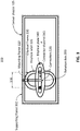
- Figure 3 illustrates an end view of a server chassis having a blind mating adapter unit, according to some embodiments.
- the view is from the rear of the server rack in which the server chassis is installed.
- the server is installed from the front of the server rack, and slid into place inside the server rack.
- the fluid connectors 120 on the blind mating adapter unit 300 couple to corresponding mating fluid connectors on coolant distribution manifolds 201/202 (not shown) in the rear of the server rack (not shown).
- the fluid connectors 120 on the blind mating adapter unit 300 are initially configured to align with corresponding fluid connectors on the coolant distribution manifolds (not shown).
- the server chassis 105 can be removed and reinstalled by blind mating without further adjustment.
- the blind mating adapter unit 300 is installed onto the server chassis 105 and configured for alignment before inserting the server chassis 105 into the server rack.
- Blind mating adapter unit 300 can include mounting frame 310, elliptical frame 330, elliptical plate 340, and rotation axis 350.
- Elliptical frame 330, elliptical plate 340, and rotation axis 350 can be coupled using mounting frame 310.
- Mounting frame 310 can be adjustably coupled to supporting frame 302. In an embodiment, mounting frame 310 can be adjusted in a left-right direction (x-axis), across the long edge of the server chassis 105.
- Supporting frame 302 can be coupled to server chassis 105.
- Elliptical frame 335 comprises an elongated oval or "racetrack” shape having two elongated parallel sides 336.
- Elliptical plate 340 comprises an oblong plate having a straight connector channel 345 with rounded ends.
- Elliptical frame 330 forms an open channel termed an elliptical orbit 335. Fluid connectors 120, and their associated coolant supply and return lines (not shown), traverse, or “go through", the elliptical orbit 335 and the connector channel 345 of elliptical plate 340.
- a location of the fluid connectors 120, and associated coolant supply and return lines is determined by the intersection of the fluid connector 120 and coolant line with the connector channel 345 of the rotatable elliptical plate 340 and the elliptical orbit 335 of the elliptical frame 330.
- Elliptical plate 340 can be rotated about the rotation axis 350 causing the locations of the fluid connectors 120 to follow the connector channel 345 of the rotatable elliptical plate 340 and the elliptical orbit 335 of the elliptical frame 330.
- Fluid connectors 120 can be aligned for blind mating with corresponding mating fluid connectors on the coolant distribution manifolds 201/2 (not shown).
- a manner of assembling of the coolant lines (not shown) and fluid connectors 120 with the blind adapting unit 300 can depend upon how the coolant lines are furnished with the cooling module in the server.
- the coolant lines may be furnished with one end of each coolant line pre-coupled to the coolant module inside the server.
- a server provider may typically assume that it is the end user's responsibility to determine how to couple the other end of each coolant line to the coolant distribution manifold in the server rack according to that particular user's coolant distribution manifold and server rack configuration.
- a server manufacturer may furnish coolant lines with the server such that the end of each coolant line that is to be connected with a coolant distribution manifold is either (1) furnished with no fluid connector, (2) furnished with a loose, uninstalled fluid connector, or (3) furnished with a fluid connector installed on the end of the coolant line that is to be coupled to the coolant distribution manifold.
- the fluid connector that is installed on the coolant line can be removed.
- the coolant line can be inserted from the back side (the side facing the cooling module in the server) of the blind mating adapter unit, through the elliptical orbit 335, and through the connector channel 345.
- the fluid connector 120 can be installed on the end of the coolant line (not shown).
- the elliptical orbit 335, connector channel 345, and fluid connectors 120 are configured to (1) slidably fit the coolant line (with fluid connectors 120 removed) through the elliptical orbit 335 and connector channel 345, (2) to enable rotation of the elliptical plate 340 with the coolant line and fluid connectors 120 coupled, (3) prevent the fluid connectors 120 from being pushed through the connector channel and/or elliptical orbit 335 due to the force of blind mating when installing the server into the server rack, and (4) secure the fluid connectors 120 to the blind mating adapter unit such that the force of removing server and disconnecting the blind mated fluid connectors does not pull the coolant line out from the blind mating adapter unit, the server, or from the coolant module.
- a width of the elliptical orbit 335 and a width of the connector channel 345 can be selected to be slightly larger than an outside diameter of the coolant line (not shown). Slightly larger can be, e.g., 1 to 2 mm or 1/32" to 1/16" greater than the outside diameter of the coolant line. In this way, the coolant line is free to move within the elliptical orbit 335 and connector channel 345 as the elliptical plate 340 is rotated.
- a width of elliptical orbit 335 and a width of the connector channel 345 is selected to be slightly smaller than an outer dimension of the fluid connector 120.
- a washer or similar mechanical object can be placed between the fluid connector 120 and the elliptical plate 340 to prevent the fluid connector 120 from being pushed through the connector channel 345 during blind mating.
- a mechanical retainer element such as a hose clamp, rubber collar, or other mechanical restraint, can be installed on the coolant line (not shown) before inserting the coolant line through elliptical orbit 335 and the connector channel 345, to prevent the coolant line from being pulled out from the server due to the force of disconnecting the blind mated fluid connectors when removing the server from the server rack.
- Figure 4 illustrates is a section view of a blind mating adapting unit for use in a server chassis, according to some embodiments.
- Supporting frame 302 can be attached to a chassis of the server (not shown).
- Mounting frame 310 can couple elliptical frame 330, elliptical plate 340, and rotation axis 350 to supporting frame 302.
- fluid connectors 120 are positioned substantially horizontally, such that a first fluid connector 120 (shaded) appears in front of rotation axis 350.
- a second fluid connector 120 (not visible) is positioned behind both the first fluid connector 120 (shaded) and rotation axis 350.
- each coolant line 131 and 132 (collectively, 131/2) has a fluid connector coupled to the coolant line 131/2 through the blind mating adapter unit.
- a second end (not shown) of each coolant line 131/2 can be coupled to the cooling module inside the server (not shown).
- Figures 5A and 5B illustrate detailed views of components of a blind mating adapter unit according to some embodiments.
- a portion of the blind mating adapter includes an elliptical plate 340 having a connector channel 345 centered about a rotation axis 350.
- the elliptical frame (not shown here), elliptical plate 340, and rotation axis 350 can be coupled together by mounting frame (not shown here).
- coolant lines 131 can 132 can be inserted from the back of the blind mating adapter unit (from the cooling module inside the server) through the elliptical frame (not shown here) and elliptical plate 340.
- the coolant lines 131 and 132 are configured to rotate or adjust along a rotation path defined by the elliptical orbit of elliptical frame (not shown) and the connector channel 345 of elliptical plate 340.
- Elliptical plate 340 can have a connector channel sleeve 346 configured to facilitate smooth rotation of the cooling lines 131 and 132 along the rotation path, to reduce or eliminate binding of the coolant lines 131 and 132 during rotation along the rotation path, and to guide the coolant lines toward the mating fluid connectors on the coolant distribution manifolds (not shown).
- Connector channel sleeve 346 can be, e.g., a band of metal, e.g.
- elliptical plate 340 can start as a single portion of metal, e.g., 1/16" thick steel, aluminum, or stainless steel, and the connector channel 345 and connector channel sleeve 346 can be formed by a metal press or stamping operation.
- the rotation axis 350 is a unit which includes a fixing portion 351 that is fixedly coupled to the mounting frame (not shown) and does not rotate.
- the rotating portion 352 is free to rotate as the elliptical plate 340 is rotated.
- the elliptical plate 340 is rotated to position coolant lines 131 and 132 and their respective fluid connectors (not shown) for alignment with the mating connectors on the coolant distribution manifold.
- the rotating portion 352 rotates smoothly and continuously with respect to the fixing portion 351.
- the rotating portion 352 can mechanically stop at one of the positioning points 353.
- the detent can be overcome and the rotation of the elliptical plate 340 can stop at a next positioning point 353.
- Figure 6 illustrates an end view of a server chassis 105 having two elliptical blind mating adapter units 300, according to some embodiments.
- the blind mating adapter units 300 can be as described with referenced to Figures 2-4 and 5A and 5B , above.
- Embodiments as shown in Figure 6 can be used, e.g., when a single server chassis 105 includes two cooling modules, each cooling module having its own respective pair of coolant supply and return lines.
- Figure 6 can also be used when a single cooling module requires greater coolant flow that can be provided by a single coolant distribution manifold.
- a coolant supply line from the elliptical adapter 300 on the left may be coupled to a coolant supply line from the elliptical adapter 300 on the right using, e.g., a 2-into-1 connector inside the server chassis, and can be coupled to a single larger coolant supply on the cooling module.
- the single, larger coolant return line from the cooling module may be split using a 1-into-2 connector inside the server, and one of the two coolant return lines can be coupled to the elliptical adapter 300 on the left and one of the coolant return lines can be coupled to the coolant return line of the right elliptical adapter 300.
- each of the two elliptical adapters can be assembled to its own mounting frame 310, and each mounting frame 310 can be slidably coupled to the supporting frame 302.
- the supporting frame 302 is coupled to the server chassis 105.
- Figure 7 illustrates and end view of details of components of a blind mating adapter unit, according to one embodiment. More specifically, Figure 7 illustrates the relationship between predetermined fixed positions of the rotation axis 350, corresponding positions of the elliptical plate 340 and coolant lines 131 and 132, and coolant distribution manifolds 201 and 202 in server rack 200.
- Figure 7 is divided into three related portions.
- a rotation axis 350 as described with reference to Figure 5B , above.
- the rotation axis 350 illustrates predetermined fixed positions #1 through #5.
- an elliptical plate 340 having a rotation axis 350 is shown at predetermined fixed positions #1 through #5, corresponding to positions #1 through #5 of the rotation axis 350.
- the elliptical plate 340 is described above with reference to Figure 5A .
- a server rack 200 containing a plurality of servers 203 is shown.
- Each server 203 is configured to blind mate coolant lines 131 and 132 from the server 203 to coolant distribution manifolds 201 and 202 using the blind mating adapter described in Figures 1-6 , above.
- Positions of coolant lines 131 and 132 for each server 203 are as shown in corresponding positions #1 through #5 of the rotation axis 350 and positions #1 through #5 of the elliptical plate 340 having the rotation axis 350.
- References 131 and 132 can also be understood as the end of the coolant supply line and coolant return line, which are the fluid connectors. They can also be understood as the fluid connectors that will blind mate to corresponding fluid connectors on the coolant distribution manifold.
- FIG 8 illustrates a perspective view of two server chassis each having a blind mating adapter unit, according to one embodiment.
- different blind mating adapter units can have different sided elliptical orbits 335 and different elliptical plates for different separation or configuration of coolant distribution manifolds 201 and 202 (not shown).
- the blind mating adapter units can be slidably coupled to a supporting frame 302 that is coupled a server chassis 105.
- the fluid connectors of the blind mating adapters are configured to blind mate to corresponding mating adapters on coolant distribution manifolds (not shown).
- a location of the blind mating adapter unit on the server chassis is adjustable, using the supporting frame, in a horizontal direction (x-axis) with respect to a direction facing into the electronic rack from the front or back of the electronic rack.
- a location of the plurality of fluid connectors can be adjusted in the vertical direction (y-axis). Adjustment in the vertical direction can be implemented by rotating the elliptical plate 340, by changing, or adjusting, a length of the mounting frame 310, or by adjusting a vertical location of the blind mating adapter unit using the supporting frame 302.
- Figure 9 illustrates an end view of a plurality of servers 203 in a server rack 200, each server 203 having a blind mating adapter unit with an elliptical frame 330, elliptical orbit 335, and elliptical plate 340.
- Connector channel 345 and elliptical orbit 334 define a rotation path for fluid connectors 120 of coolant lines (not shown).
- the elliptical frame 330, elliptical plate 340, and rotation axis 350 are coupled to mounting frame 310.
- Mounting frame 310 is slidably coupled to supporting frame 302.
- Mounting frame 310 is slidably adjusted to center the rotation axis 350 between rack manifolds 201 and 202.
- Elliptical plate 340 is rotated to align fluid connectors 120 to blind mate with corresponding mating fluid connectors on rack manifolds 201 and 202. After initial alignment of the blind mating adapter and fluid connectors on the server to the corresponding mating adapters on the rack manifolds, the server can be repeatedly removed and re-installed without further alignment of the fluid connectors using the blind mating adapter unit.
- Unused fluid connectors 212 are mating connectors on coolant distribution manifolds 201 and 202.
- a user could have chosen to rotate elliptical plate 340 approximately 90° counter- clockwise from the position shown in Figure 9 for server #2 (203), to use coolant distribution manifold connectors 212 for blind mating, instead of using the coolant distribution manifold fluid connectors as shown in Figure 9 for server #2 (203).
Landscapes
- Engineering & Computer Science (AREA)
- Physics & Mathematics (AREA)
- Microelectronics & Electronic Packaging (AREA)
- General Engineering & Computer Science (AREA)
- Theoretical Computer Science (AREA)
- Computer Hardware Design (AREA)
- Thermal Sciences (AREA)
- Human Computer Interaction (AREA)
- General Physics & Mathematics (AREA)
- Power Engineering (AREA)
- Cooling Or The Like Of Electrical Apparatus (AREA)
- Cooling Or The Like Of Semiconductors Or Solid State Devices (AREA)
- Snaps, Bayonet Connections, Set Pins, And Snap Rings (AREA)
Abstract
A blind mating adapter unit is disclosed that is adjustably locatable on a server chassis. The blind mating adapter unit is rotatably adjustable to align the orientation of one or more fluid connectors on the blind mating adapter unit to a corresponding one or more mating fluid connectors on a coolant distribution manifold installed in a server rack. An elliptical frame having an elliptical orbit, coupled to an elliptical plate having a connector channel, can be rotated about a rotation axis continuously or in fixed increments. The connector channel and elliptical orbit define a rotation path for the aligning the fluid connectors and the rotation axis defines the position of the fluid connectors on the rotation path. When the server is slid into place in the server rack, the fluid connectors on the blind mating adapter fluidly couple to the corresponding mating fluid connectors on the coolant distribution manifold. The blind mating adapter unit functions as an intermediate layer for server and rack fluid mating.
Description
- Embodiments of the present invention relate generally to data center cooling. More particularly, embodiments of the invention relate to server racks, including installation and removal of server equipment that connects to a liquid cooling module.
- Cooling is a prominent factor in a computer system and data center design. The number of high performance electronics components such as high performance processors packaged inside servers has steadily increased, thereby increasing the amount of heat generated and dissipated during the ordinary operations of the servers. The reliability of servers used within a data center decreases if the environment in which they operate is permitted to increase in temperature over time. Maintaining a proper thermal environment is critical for normal operations of these servers in data centers, as well as the server performance and lifetime. It requires more effective and efficient cooling solutions especially in the cases of cooling these high performance servers.
- A server rack in a data center may contain servers and/or cooling distribution units having different types, sizes, gender, and location of liquid coolant connections. Typically, in a server rack, a coolant distribution unit couples to a coolant distribution manifold at the back of the server rack. Each server that requires liquid cooling will be connected to the coolant distribution manifold. The coolant distribution manifold often comprises a variety of interconnection hoses or a pair of distribution manifolds in the form of sealed square tubing with fluid connectors placed at fixed intervals along the tubing of the manifold. There are different types of rack manifold designs for server rack equipment connection sizes, locations, connector types, or genders. Servers and cooling distribution units in server racks require periodic service such that it is necessary to disconnect the liquid coolant connections at the back of the server rack to remove and service the server. Those connections are often deep in the back of the server rack and are not easily accessible.
- In a first aspect, a blind mating adapter unit configured to fluidly couple a server in an electronic rack to one or more coolant distribution manifolds via blind mating is provided. The blind mating adapter unit includes: an elliptical frame having an elliptical orbit about a center point of the elliptical frame configured to position a plurality of fluid connectors within the elliptical orbit; and an elliptical plate having a connector channel and a rotation axis, wherein the elliptical plate is configured to rotate about the rotation axis of the elliptical plate, wherein the plurality of fluid connectors are configured to traverse both the elliptical orbit of the elliptical frame and the connector channel of the elliptical plate, and wherein the blind mating adapter unit is configurable to fix an alignment of the plurality of fluid connectors to a plurality of mating fluid connectors on one or more coolant distribution manifolds in the electronic rack, such that when the server chassis is installed into the electronic rack, the plurality of fluid connectors are blind mated to the mating plurality of fluid connectors on the one or more coolant distribution manifolds.
- In a second aspect, a server of an electronic rack is provided. The server includes: a cooling module comprising a coolant supply line, a heat transfer unit, and a coolant return line, wherein a first end of the coolant supply line and a first end of the coolant return line are coupled to the heat transfer unit; a blind mating adapter unit adjustably coupled to a chassis of the server, wherein the blind mating adapter unit includes: an elliptical frame having an elliptical orbit about a center point of the elliptical frame configured to position a plurality of fluid connectors within the elliptical orbit; an elliptical plate having a connector channel and a rotation axis, wherein the elliptical plate is configured to rotate about the rotation axis of the elliptical frame; wherein the plurality of fluid connectors and a second end of the coolant supply line and a second end of the coolant return line are configured to traverse both the elliptical orbit of the elliptical frame and the connector channel of the elliptical plate, and wherein the blind mating adapter unit is configurable to fix an alignment of the plurality of fluid connectors to a plurality of mating fluid connectors on one or more coolant distribution manifolds in the electronic rack, such that when the server chassis is installed into the electronic rack, the plurality of fluid connectors are blind mated to the mating plurality of fluid connectors on the one or more coolant distribution manifolds.
- In a third aspect, an electronic rack is provided. The electronic rack includes: one or more coolant distribution manifolds; and a plurality of servers arranged in a stack, wherein each server includes: a cooling module comprising a coolant supply line, a heat transfer unit, and a coolant return line, wherein a first end of the coolant supply line and a first end of the coolant return line are coupled to the heat transfer unit; a blind mating adapter unit adjustably coupled to a chassis of the server, wherein the blind mating adapter unit includes: an elliptical frame having an elliptical orbit about a center point of the elliptical frame configured to position a plurality of fluid connectors within the elliptical orbit; an elliptical plate having a connector channel and a rotation axis, wherein the elliptical plate is configured to rotate about the rotation axis of the elliptical frame; wherein the plurality of fluid connectors and a second end of the coolant supply line and a second end of the coolant return line are configured to traverse both the elliptical orbit of the elliptical frame and the connector channel of the elliptical plate, and wherein the blind mating adapter unit is configurable to fix an alignment of the plurality of fluid connectors to a plurality of mating fluid connectors on the one or more coolant distribution manifolds in the electronic rack, such that when the server chassis is installed into the electronic rack, the plurality of fluid connectors are blind mated to the mating plurality of fluid connectors on the one or more coolant distribution manifolds.
- Embodiments of the invention are illustrated by way of example and not limitation in the figures of the accompanying drawings in which like references indicate similar elements.
-
Figure 1 is a block diagram illustrating an example of a cooling module in a server chassis having a blind mating adapting unit, according to one embodiment. -
Figure 2 illustrates plan view of an embodiment of a server chassis having a blind mating adapter unit, according to some embodiments. -
Figure 3 illustrates an end view of a server chassis having a blind mating adapter unit, according to some embodiments. -
Figure 4 illustrates is a section view of a blind mating adapter unit for use in a server chassis, according to some embodiments. -
Figures 5A and 5B illustrate detail views of components of a blind mating adapter unit according to some embodiments. -
Figure 6 illustrates an end view of a server chassis having two blind mating adapter units, according to some embodiments. -
Figure 7 illustrates an end view of details of components of a blind mating adapter unit, according to one embodiment. -
Figure 8 illustrates a perspective view of two server chassis each having a blind mating adapter unit, according to one embodiment. -
Figure 9 illustrates an end view of a plurality of server chassis in a server rack, each server having a blind mating adapter unit, according to one embodiment. - Various embodiments and aspects of the inventions will be described with reference to details discussed below, and the accompanying drawings will illustrate the various embodiments. The following description and drawings are illustrative of the invention and are not to be construed as limiting the invention. Numerous specific details are described to provide a thorough understanding of various embodiments of the present invention. However, in certain instances, well-known or conventional details are not described in order to provide a concise discussion of embodiments of the present inventions.
- Reference in the specification to "one embodiment" or "an embodiment" means that a particular feature, structure, or characteristic described in conjunction with the embodiment can be included in at least one embodiment of the invention. The appearances of the phrase "in one embodiment" in various places in the specification do not necessarily all refer to the same embodiment.
- In a first aspect, a blind mating adapter unit is configured to fluidly couple a server in an electronic rack (also termed "server rack") to a coolant distribution manifold via blind mating. Blind mating happens via a sliding or snapping action which can be accomplished without wrenches or other tools. Blind mating can include self-aligning features which allow a small misalignment when mating. The blind mating adapter unit can be installed onto the server chassis and configured for alignment before inserting the server into the server rack. The blind mating adapter unit can include an elliptical frame having an elliptical orbit about a center point of the elliptical frame, configured to position a plurality of fluid connectors within the elliptical orbit. The plurality of fluid connectors may be provided by coolant supply and return lines of a cooling module in the server. The blind mating adapter can also include an elliptical plate having a connector channel and a rotation axis. The elliptical plate is configured to rotate about the rotation axis of the elliptical frame. The plurality of fluid connectors are configured to traverse, or cross through, both the elliptical orbit of the elliptical frame and the connector channel of the elliptical plate. The blind mating adapter unit is configurable to fix an alignment of the plurality of fluid connectors to a plurality of mating fluid connectors on a coolant distribution manifold in the server rack. When the server chassis is installed into the server rack, the plurality of fluid connectors are blind mated to the mating plurality of fluid connectors on the coolant distribution manifold.
- In an embodiment, the blind mating adapter unit further includes a mounting frame. The elliptical plate, elliptical frame, and rotation axis are adjustably coupled to a chassis of the server by the mounting frame. The mounting frame fixes the rotation axis of the elliptical plate at the center point of the elliptical frame. In an embodiment, the fluid connectors of the blind mating adapter unit are rotatable within ±90° or ±180° about the rotation axis. The elliptical orbit comprises two elongated and parallel sides forming a pair of parallel channels. The fluid connectors can move within the elliptical orbit as the elliptical plate is rotated about the rotation axis. The elliptical orbit of the elliptical frame and the connector channel of the elliptical plate form a rotation path for the plurality of fluid connectors. The rotation axis can comprise a bearing assembly. The bearing assembly can include a plurality of predetermined detent positions at which the elliptical plate can be rotatably positioned with the rotation path. The blind mating adapter unit can further include a connector channel sleeve whose sides are perpendicular to the elliptical plate and substantially parallel a plurality of coolant lines traversing (crossing through) the elliptical frame and elliptical plate.
- In an embodiment, a location of the blind mating adapter unit on the server chassis is adjustable, using the supporting frame, in a horizontal direction (x-axis) with respect to a direction facing into the electronic rack from the front or back of the electronic rack. In an embodiment, a location of the plurality of fluid connectors can be adjusted in the vertical direction (y-axis). Adjustment in the vertical direction can be implemented by rotating the elliptical plate, by changing, or adjusting, a length of the mounting frame, or by adjusting a vertical location of the blind mating adapter unit using the supporting frame.
- In a second aspect, a server can include a cooling module having a coolant supply line, a heat transfer unit, and a coolant return line. The server can further include a blind mating adapter unit having a plurality of fluid connectors that are adjustably configurable to blind mate to a corresponding plurality of mating fluid connectors on a coolant distribution manifold, as described in the first aspect, above.
-
Figure 1 is a block diagram illustrating an example of a cooling module in a server chassis having a blind mating adapting unit, according to one embodiment. Thecooling module 100 can include a processor/cold plate assembly that removes heat fromprocessor chip 101. Referring toFigure 1 ,processor 101 is plugged onto a processor socket mounted on printed circuit board (PCB) ormotherboard 102 coupled to other electrical components or circuits of a data processing system or server.Processor 101 includes acold plate 103 attached to it, which is coupled to a rack manifold that is coupled toliquid supply line 132 and/orliquid return line 131. The coupling of thecold plate 103 to the rack manifold, viacoolant lines processor 101 is removed by the coolingliquid lines cold plate 103. The remaining portion of the heat enters into an air space underneath or above, which may be removed by an airflow generated by a cooling fan (not shown). A blindmating adapter unit 110, as described herein, can be coupled to theserver chassis 105 using a frame (not shown). The cold plate coolingliquid lines mating adapting unit 110 mounted to the frame on the server chassis to enable blind mating of the server's cooling lines to one or more coolant distribution manifolds in the server rack that house theserver chassis 105. Theliquid supply line 131 andliquid return line 132 can be hoses with either blind mating connectors. Thecooling module 100 included in theserver chassis 105 may be used in different types of servers and server racks. Blindmating adapter unit 110 can ensure proper mating and configuration for the fluid systems between the server rack and the cooling module(s) in the server. -
Figure 2 illustrate plan view of an embodiment of aserver 203 having a blind mating adapter unit, according to some embodiments. The blind mating adapter unit enables a piece of information technology (IT) equipment, such as aserver 203, to be slid into theserver rack 200 and blind mated to a portion of the fluid connectors on thecoolant distribution manifolds 201 and 202 (collectively, 201/2) via the blind mating adapter unit. Thefluid connectors 120 on the blind mating adapter unit are initially configured to align with corresponding fluid connectors on thecoolant distribution manifolds 201/2. Theserver 203 can be repeatedly removed from the server rack and reinstalled by blind mating, without further adjustment. In an embodiment, the blind mating adapter unit is installed into theserver 203 chassis and configured for alignment before inserting theserver 203 into the server rack. The blind mating adapter unit enables blind mating to fluid connectors on server rack coolant distribution manifolds for different cooling modules in a server chassis and different rack designs. - In
Figure 2 , aserver 203 is illustrated that has a cooling module (not shown) included within theserver 203 as described above, with reference toFigure 1 . The cooling module is described above with reference toFigure 1 . The cooling module within theserver 203 may include one or more hoses, tubes, or piping such as for acoolant supply line 131 and acoolant return line 132, or other coolant line. The coolant lines can be fluidly coupled at one end to the cooling module (not shown) in theserver 203. The other end of each of thecoolant supply 131 andcoolant return lines 132 can be adjustably coupled to the blind mating adapter unit, as described herein and with reference toFigures 3-9 . In an embodiment, thecoolant lines fluid connectors 120 on their ends. - A blind mating adapter unit can align a plurality of
fluid connectors 120 on a plurality ofcoolant lines elliptical frame 330 and anelliptical plate 340. An elliptical orbit ofelliptical plate 330 and a connector channel orelliptical plate 340 form a rotation path within whichfluid connectors 120 andcoolant hoses elliptical frame 330,elliptical plate 340, and rotation axis (not shown) can be assembled to a mountingframe 310 that is coupled to a chassis ofserver 203 such that thefluid connectors 120 and associatedcoolant lines fluid connectors 120 are rotated to align with correspondingmating fluid connectors 212 oncoolant distribution manifolds 201/2. After alignment, theserver 203 can be removed and reinstalled into the server rack, by blind mating, without further adjustment. - The blind mating adapter unit can be adjustably mounted to the chassis of the
server 203 using mountingframe 310 and supportingframe 302. The mountingframe 310 of the blind mating adapter unit is adjustably coupled to the supportingframe 302 to facilitate alignment of thefluid connectors 120 with the correspondingmating fluid connectors 212 on thecoolant distribution manifolds 201/2. -
Figure 3 illustrates an end view of a server chassis having a blind mating adapter unit, according to some embodiments. The view is from the rear of the server rack in which the server chassis is installed. The server is installed from the front of the server rack, and slid into place inside the server rack. Upon sliding theserver chassis 105 into the server rack, thefluid connectors 120 on the blindmating adapter unit 300 couple to corresponding mating fluid connectors oncoolant distribution manifolds 201/202 (not shown) in the rear of the server rack (not shown). Thefluid connectors 120 on the blindmating adapter unit 300 are initially configured to align with corresponding fluid connectors on the coolant distribution manifolds (not shown). Theserver chassis 105 can be removed and reinstalled by blind mating without further adjustment. In an embodiment, the blindmating adapter unit 300 is installed onto theserver chassis 105 and configured for alignment before inserting theserver chassis 105 into the server rack. - Dashed
line 105 represents a chassis of the server. Blindmating adapter unit 300 can include mountingframe 310,elliptical frame 330,elliptical plate 340, androtation axis 350.Elliptical frame 330,elliptical plate 340, androtation axis 350 can be coupled using mountingframe 310. Mountingframe 310 can be adjustably coupled to supportingframe 302. In an embodiment, mountingframe 310 can be adjusted in a left-right direction (x-axis), across the long edge of theserver chassis 105. Supportingframe 302 can be coupled toserver chassis 105. -
Elliptical frame 335 comprises an elongated oval or "racetrack" shape having two elongatedparallel sides 336.Elliptical plate 340 comprises an oblong plate having astraight connector channel 345 with rounded ends.Elliptical frame 330 forms an open channel termed anelliptical orbit 335.Fluid connectors 120, and their associated coolant supply and return lines (not shown), traverse, or "go through", theelliptical orbit 335 and theconnector channel 345 ofelliptical plate 340. A location of thefluid connectors 120, and associated coolant supply and return lines (not shown), is determined by the intersection of thefluid connector 120 and coolant line with theconnector channel 345 of the rotatableelliptical plate 340 and theelliptical orbit 335 of theelliptical frame 330.Elliptical plate 340 can be rotated about therotation axis 350 causing the locations of thefluid connectors 120 to follow theconnector channel 345 of the rotatableelliptical plate 340 and theelliptical orbit 335 of theelliptical frame 330.Fluid connectors 120 can be aligned for blind mating with corresponding mating fluid connectors on thecoolant distribution manifolds 201/2 (not shown). - A manner of assembling of the coolant lines (not shown) and
fluid connectors 120 with theblind adapting unit 300 can depend upon how the coolant lines are furnished with the cooling module in the server. In a typical installation, the coolant lines may be furnished with one end of each coolant line pre-coupled to the coolant module inside the server. A server provider may typically assume that it is the end user's responsibility to determine how to couple the other end of each coolant line to the coolant distribution manifold in the server rack according to that particular user's coolant distribution manifold and server rack configuration. Accordingly, a server manufacturer may furnish coolant lines with the server such that the end of each coolant line that is to be connected with a coolant distribution manifold is either (1) furnished with no fluid connector, (2) furnished with a loose, uninstalled fluid connector, or (3) furnished with a fluid connector installed on the end of the coolant line that is to be coupled to the coolant distribution manifold. In the latter case, (3), the fluid connector that is installed on the coolant line can be removed. Then for all cases (1), (2), and (3), the coolant line can be inserted from the back side (the side facing the cooling module in the server) of the blind mating adapter unit, through theelliptical orbit 335, and through theconnector channel 345. Then thefluid connector 120 can be installed on the end of the coolant line (not shown). - The
elliptical orbit 335,connector channel 345, andfluid connectors 120 are configured to (1) slidably fit the coolant line (withfluid connectors 120 removed) through theelliptical orbit 335 andconnector channel 345, (2) to enable rotation of theelliptical plate 340 with the coolant line andfluid connectors 120 coupled, (3) prevent thefluid connectors 120 from being pushed through the connector channel and/orelliptical orbit 335 due to the force of blind mating when installing the server into the server rack, and (4) secure thefluid connectors 120 to the blind mating adapter unit such that the force of removing server and disconnecting the blind mated fluid connectors does not pull the coolant line out from the blind mating adapter unit, the server, or from the coolant module. To address these issues, a width of theelliptical orbit 335 and a width of theconnector channel 345 can be selected to be slightly larger than an outside diameter of the coolant line (not shown). Slightly larger can be, e.g., 1 to 2 mm or 1/32" to 1/16" greater than the outside diameter of the coolant line. In this way, the coolant line is free to move within theelliptical orbit 335 andconnector channel 345 as theelliptical plate 340 is rotated. Similarly, a width ofelliptical orbit 335 and a width of theconnector channel 345 is selected to be slightly smaller than an outer dimension of thefluid connector 120. This prevents thefluid connector 120 from being pushed throughconnector channel 345 or theelliptical orbit 335 due to the force of blind mating thefluid connectors 120 with corresponding mating fluid adapters on the coolant distribution manifold, when installing the server into the server rack. In an embodiment, a washer or similar mechanical object can be placed between thefluid connector 120 and theelliptical plate 340 to prevent thefluid connector 120 from being pushed through theconnector channel 345 during blind mating. In an embodiment, a mechanical retainer element, such as a hose clamp, rubber collar, or other mechanical restraint, can be installed on the coolant line (not shown) before inserting the coolant line throughelliptical orbit 335 and theconnector channel 345, to prevent the coolant line from being pulled out from the server due to the force of disconnecting the blind mated fluid connectors when removing the server from the server rack. -
Figure 4 illustrates is a section view of a blind mating adapting unit for use in a server chassis, according to some embodiments. Supportingframe 302 can be attached to a chassis of the server (not shown). Mountingframe 310 can coupleelliptical frame 330,elliptical plate 340, androtation axis 350 to supportingframe 302. In this section view,fluid connectors 120 are positioned substantially horizontally, such that a first fluid connector 120 (shaded) appears in front ofrotation axis 350. A second fluid connector 120 (not visible) is positioned behind both the first fluid connector 120 (shaded) androtation axis 350. A first end of eachcoolant line 131 and 132 (collectively, 131/2) has a fluid connector coupled to thecoolant line 131/2 through the blind mating adapter unit. A second end (not shown) of eachcoolant line 131/2 can be coupled to the cooling module inside the server (not shown). -
Figures 5A and 5B illustrate detailed views of components of a blind mating adapter unit according to some embodiments. - Referring now to
Figure 5A , a portion of the blind mating adapter includes anelliptical plate 340 having aconnector channel 345 centered about arotation axis 350. As described above, with reference toFigures 2 through 4 , the elliptical frame (not shown here),elliptical plate 340, androtation axis 350 can be coupled together by mounting frame (not shown here). As also described above, with reference toFigures 2 through 4 ,coolant lines 131 can 132 can be inserted from the back of the blind mating adapter unit (from the cooling module inside the server) through the elliptical frame (not shown here) andelliptical plate 340. Thecoolant lines connector channel 345 ofelliptical plate 340.Elliptical plate 340 can have aconnector channel sleeve 346 configured to facilitate smooth rotation of the coolinglines coolant lines Connector channel sleeve 346 can be, e.g., a band of metal, e.g. 1/2" to 1" wide, shaped as shown inFigure 5A , and welded, brazed, or otherwise physically attached toelliptical plate 340. In an embodiment,elliptical plate 340 can start as a single portion of metal, e.g., 1/16" thick steel, aluminum, or stainless steel, and theconnector channel 345 andconnector channel sleeve 346 can be formed by a metal press or stamping operation. - Referring now to
Figure 5B , therotation axis 350 is a unit which includes a fixingportion 351 that is fixedly coupled to the mounting frame (not shown) and does not rotate. The rotatingportion 352 is free to rotate as theelliptical plate 340 is rotated. Theelliptical plate 340 is rotated to positioncoolant lines portion 352 rotates smoothly and continuously with respect to the fixingportion 351. In an embodiment, there are a plurality ofpredetermined positioning points 353 that act as detents, to stop the rotation at one of the predetermined points 353. When rotating theelliptical plate 340, the rotatingportion 352 can mechanically stop at one of the positioning points 353. With additional rotating force applied to theelliptical pate 340, the detent can be overcome and the rotation of theelliptical plate 340 can stop at anext positioning point 353. -
Figure 6 illustrates an end view of aserver chassis 105 having two elliptical blindmating adapter units 300, according to some embodiments. The blindmating adapter units 300 can be as described with referenced toFigures 2-4 and5A and 5B , above. Embodiments as shown inFigure 6 can be used, e.g., when asingle server chassis 105 includes two cooling modules, each cooling module having its own respective pair of coolant supply and return lines.Figure 6 can also be used when a single cooling module requires greater coolant flow that can be provided by a single coolant distribution manifold. In such case, a coolant supply line from theelliptical adapter 300 on the left may be coupled to a coolant supply line from theelliptical adapter 300 on the right using, e.g., a 2-into-1 connector inside the server chassis, and can be coupled to a single larger coolant supply on the cooling module. Similarly, the single, larger coolant return line from the cooling module may be split using a 1-into-2 connector inside the server, and one of the two coolant return lines can be coupled to theelliptical adapter 300 on the left and one of the coolant return lines can be coupled to the coolant return line of the rightelliptical adapter 300. - As described above with reference to
Figures 1-4 and5A and 5B , each of the two elliptical adapters can be assembled to itsown mounting frame 310, and each mountingframe 310 can be slidably coupled to the supportingframe 302. The supportingframe 302 is coupled to theserver chassis 105. -
Figure 7 illustrates and end view of details of components of a blind mating adapter unit, according to one embodiment. More specifically,Figure 7 illustrates the relationship between predetermined fixed positions of therotation axis 350, corresponding positions of theelliptical plate 340 andcoolant lines coolant distribution manifolds server rack 200. -
Figure 7 is divided into three related portions. At left inFigure 7 is arotation axis 350 as described with reference toFigure 5B , above. Therotation axis 350 illustrates predetermined fixedpositions # 1 through #5. At center inFigure 7 , anelliptical plate 340 having arotation axis 350 is shown at predetermined fixedpositions # 1 through #5, corresponding topositions # 1 through #5 of therotation axis 350. Theelliptical plate 340 is described above with reference toFigure 5A . At right inFigure 7 , aserver rack 200 containing a plurality ofservers 203 is shown. Eachserver 203 is configured to blindmate coolant lines server 203 tocoolant distribution manifolds Figures 1-6 , above. Positions ofcoolant lines server 203 are as shown incorresponding positions # 1 through #5 of therotation axis 350 andpositions # 1 through #5 of theelliptical plate 340 having therotation axis 350.References -
Figure 8 illustrates a perspective view of two server chassis each having a blind mating adapter unit, according to one embodiment. As indicated inFigure 8 , different blind mating adapter units can have different sidedelliptical orbits 335 and different elliptical plates for different separation or configuration ofcoolant distribution manifolds 201 and 202 (not shown). The blind mating adapter units can be slidably coupled to a supportingframe 302 that is coupled aserver chassis 105. When each of theserver chassis 105 is installed into a server rack (not shown), the fluid connectors of the blind mating adapters are configured to blind mate to corresponding mating adapters on coolant distribution manifolds (not shown). In an embodiment, a location of the blind mating adapter unit on the server chassis is adjustable, using the supporting frame, in a horizontal direction (x-axis) with respect to a direction facing into the electronic rack from the front or back of the electronic rack. In an embodiment, a location of the plurality of fluid connectors can be adjusted in the vertical direction (y-axis). Adjustment in the vertical direction can be implemented by rotating theelliptical plate 340, by changing, or adjusting, a length of the mountingframe 310, or by adjusting a vertical location of the blind mating adapter unit using the supportingframe 302. -
Figure 9 illustrates an end view of a plurality ofservers 203 in aserver rack 200, eachserver 203 having a blind mating adapter unit with anelliptical frame 330,elliptical orbit 335, andelliptical plate 340.Connector channel 345 and elliptical orbit 334 define a rotation path forfluid connectors 120 of coolant lines (not shown). Theelliptical frame 330,elliptical plate 340, androtation axis 350 are coupled to mountingframe 310. Mountingframe 310 is slidably coupled to supportingframe 302. Mountingframe 310 is slidably adjusted to center therotation axis 350 betweenrack manifolds Elliptical plate 340 is rotated to alignfluid connectors 120 to blind mate with corresponding mating fluid connectors onrack manifolds - With respect to server #2 (203), an example of two unused
fluid connectors 212 is shown. Unusedfluid connectors 212 are mating connectors oncoolant distribution manifolds Figure 5 , with reference toposition # 5, a user could have chosen to rotateelliptical plate 340 approximately 90° counter- clockwise from the position shown inFigure 9 for server #2 (203), to use coolantdistribution manifold connectors 212 for blind mating, instead of using the coolant distribution manifold fluid connectors as shown inFigure 9 for server #2 (203). - In the foregoing specification, embodiments of the invention have been described with reference to specific exemplary embodiments thereof. Different selection of connector types, hose, tubing, piping, and structural frame members, and orientations of assemblies can be implemented by one of skill in the art in possession of this disclosure. Different server rack orientations, e.g., vertical, or upward/downward, can be implemented using this disclosure. It will be evident that various modifications may be made thereto without departing from the broader spirit and scope of the invention as set forth in the following claims. The specification and drawings are, accordingly, to be regarded in an illustrative sense rather than a restrictive sense.
Claims (15)
- A blind mating adapter unit configured to fluidly couple a server in an electronic rack to one or more coolant distribution manifolds via blind mating, the blind mating adapter unit comprising:an elliptical frame (330) having an elliptical orbit about a center point of the elliptical frame (330) configured to position a plurality of fluid connectors within the elliptical orbit; andan elliptical plate (340) having a connector channel and a rotation axis, wherein the elliptical plate (340) is configured to rotate about the rotation axis of the elliptical plate (340),wherein the plurality of fluid connectors (120) are configured to traverse both the elliptical orbit of the elliptical frame (330) and the connector channel of the elliptical plate (340), andwherein the blind mating adapter unit is configurable to fix an alignment of the plurality of fluid connectors (120) to a plurality of mating fluid connectors (120) on one or more coolant distribution manifolds in the electronic rack, such that when the server chassis is installed into the electronic rack, the plurality of fluid connectors (120) are blind mated to the mating plurality of fluid connectors (120) on the one or more coolant distribution manifolds.
- The blind mating adapter of claim 1, further comprising a mounting frame (310), wherein the elliptical plate (340) and elliptical frame (330) are adjustably coupled to a chassis of the server by the mounting frame (310), and the mounting frame (310) fixes the rotation axis of the elliptical plate (340) at the center point of the elliptical frame (330).
- The blind mating adapter of claim 2, wherein the plurality of fluid connectors (120) are rotatable approximately ±90° or ±180° about the rotation axis, wherein a change in rotation of the elliptical plate (340) about the rotation axis is configured to align the plurality of fluid connectors (120) on the blind mating adapter unit to different configurations of the one or more coolant distribution manifolds or different relative locations of the plurality of mating fluid connectors (120) on the one or more coolant distribution manifolds.
- The blind mating adapter unit of any one of claim 1 to 3, wherein the elliptical orbit comprises two elongated and parallel sides forming a pair of parallel channels.
- The blind mating adapter unit of claim 2 or 3, wherein a location of the plurality of fluid connectors (120) on the server chassis is adjustable in a lateral direction (x-axis) and in a vertical direction (y-axis) with respect to a direction facing into the electronic rack from the front or back of the electronic rack.
- The blind mating adapter unit of any one of claims 2 to 5, wherein the elliptical orbit of the elliptical frame (330) and the connector channel of the elliptical plate (340) form a rotation path for the plurality of fluid connectors (120).
- The blind mating adapter unit of claim 6, the elliptical frame (330), elliptical plate (340), and rotation axis can be coupled together using a mounting frame (310), wherein the rotation axis comprises a bearing assembly and the rotation axis is coupled to the mounting frame (310).
- The blind mating adapter unit of claim 7, wherein the bearing assembly comprises a plurality of predetermined detent positions at which the elliptical plate (340) can be rotatably positioned within the rotation path.
- The blind mating adapter of any one of claims 1 to 8, wherein each fluid connector in the plurality of fluid connectors (120) is coupled to one or more coolant lines (131, 132) of a cooling module within the server chassis.
- The blind mating adapter of any one of claims 1 to 9, wherein the elliptical plate (340) further comprises a connector channel sleeve whose sides are perpendicular to the elliptical plate (340) and substantially parallel a plurality of coolant hoses coupled to the plurality of fluid connectors (120), the coolant hoses traversing the elliptical frame (330) and elliptical plate (340).
- A server of an electronic rack, comprising:a cooling module comprising a coolant supply line, a heat transfer unit, and a coolant return line, wherein a first end of the coolant supply line and a first end of the coolant return line are coupled to the heat transfer unit;a blind mating adapter unit adjustably coupled to a chassis of the server, wherein the blind mating adapter unit includes:an elliptical frame (330) having an elliptical orbit about a center point of the elliptical frame (330) configured to position a plurality of fluid connectors (120) within the elliptical orbit;an elliptical plate (340) having a connector channel and a rotation axis, wherein the elliptical plate (340) is configured to rotate about the rotation axis of the elliptical frame (330);wherein the plurality of fluid connectors (120) and a second end of the coolant supply line and a second end of the coolant return line are configured to traverse both the elliptical orbit of the elliptical frame (330) and the connector channel of the elliptical plate (340), andwherein the blind mating adapter unit is configurable to fix an alignment of the plurality of fluid connectors (120) to a plurality of mating fluid connectors on one or more coolant distribution manifolds in the electronic rack, such that when the server chassis is installed into the electronic rack, the plurality of fluid connectors (120) are blind mated to the mating plurality of fluid connectors on the one or more coolant distribution manifolds.
- The server of claim 11, wherein the blind mating adapter unit further comprises a mounting frame (310), wherein the elliptical plate (340) and elliptical frame (330) are adjustably coupled to a chassis of the server by the mounting frame (310), and the mounting frame (310) fixes the rotation axis of the elliptical plate (340) at the center point of the elliptical frame (330).
- The server of claim 11 or 12, wherein the plurality of fluid connectors (120) are provided with coolant supply and coolant return lines of the cooling module in the server.
- The server of any one of claims 11 to 13, wherein the elliptical orbit of the elliptical frame (330) and the connector of the elliptical plate (340) form a rotation path for the plurality of fluid connectors.
- An electronic rack, comprising:one or more coolant distribution manifolds; anda plurality of servers arranged in a stack, wherein each server includes:a cooling module comprising a coolant supply line, a heat transfer unit, and a coolant return line, wherein a first end of the coolant supply line and a first end of the coolant return line are coupled to the heat transfer unit;a blind mating adapter unit adjustably coupled to a chassis of the server, wherein the blind mating adapter unit includes:an elliptical frame (330) having an elliptical orbit about a center point of the elliptical frame (330) configured to position a plurality of fluid connectors (120) within the elliptical orbit;an elliptical plate (340) having a connector channel and a rotation axis, wherein the elliptical plate (340) is configured to rotate about the rotation axis of the elliptical frame (330);wherein the plurality of fluid connectors (120) and a second end of the coolant supply line and a second end of the coolant return line are configured to traverse both the elliptical orbit of the elliptical frame (330) and the connector channel of the elliptical plate (340), andwherein the blind mating adapter unit is configurable to fix an alignment of the plurality of fluid connectors (120) to a plurality of mating fluid connectors on the one or more coolant distribution manifolds in the electronic rack, such that when the server chassis is installed into the electronic rack, the plurality of fluid connectors (120) are blind mated to the mating plurality of fluid connectors on the one or more coolant distribution manifolds.
Applications Claiming Priority (1)
| Application Number | Priority Date | Filing Date | Title |
|---|---|---|---|
| US17/200,145 US11503743B2 (en) | 2021-03-12 | 2021-03-12 | High availability fluid connector for liquid cooling |
Publications (1)
| Publication Number | Publication Date |
|---|---|
| EP4057788A1 true EP4057788A1 (en) | 2022-09-14 |
Family
ID=80595358
Family Applications (1)
| Application Number | Title | Priority Date | Filing Date |
|---|---|---|---|
| EP22159169.6A Withdrawn EP4057788A1 (en) | 2021-03-12 | 2022-02-28 | A high availability fluid connector for liquid cooling |
Country Status (4)
| Country | Link |
|---|---|
| US (1) | US11503743B2 (en) |
| EP (1) | EP4057788A1 (en) |
| JP (1) | JP2022104918A (en) |
| CN (1) | CN115079796B (en) |
Families Citing this family (2)
| Publication number | Priority date | Publication date | Assignee | Title |
|---|---|---|---|---|
| US12235056B1 (en) * | 2022-12-27 | 2025-02-25 | ZT Group Int'l, Inc. | System for blind mate hydraulic connections |
| CN116126113A (en) * | 2023-03-02 | 2023-05-16 | 安徽文研科技有限公司 | Cooling device and cooling method for big data Internet server |
Citations (3)
| Publication number | Priority date | Publication date | Assignee | Title |
|---|---|---|---|---|
| US20160010772A1 (en) * | 2014-07-08 | 2016-01-14 | Staubli Faverges | Connecting plug, cooling circuit equipped with such a connecting plug and method for connecting such a cooling circuit and a cold plate |
| US20160270260A1 (en) * | 2014-01-06 | 2016-09-15 | Hewlett Packard Enterprise Development Lp | Manifolds having slidable dripless connectors |
| US20180242478A1 (en) * | 2017-02-21 | 2018-08-23 | Baidu Usa Llc | Modular self-aligning liquid heat removal coupling system for electronic racks |
Family Cites Families (13)
| Publication number | Priority date | Publication date | Assignee | Title |
|---|---|---|---|---|
| CN102375499B (en) * | 2010-08-21 | 2014-12-17 | 比亚迪股份有限公司 | Battery fixing device and laptop having same |
| US20130163185A1 (en) * | 2011-12-21 | 2013-06-27 | Microsoft Corporation | Data center docking station and cartridge |
| SG11201408001YA (en) * | 2012-08-27 | 2015-01-29 | Razer Asia Pacific Pte Ltd | Computer systems, parts of a housing for a computer system, heat exchangers, and methods for assembling parts of a computer system |
| US9763361B2 (en) * | 2015-09-14 | 2017-09-12 | Google Inc. | Blower tray |
| US10390114B2 (en) * | 2016-07-22 | 2019-08-20 | Intel Corporation | Memory sharing for physical accelerator resources in a data center |
| FR3056964B1 (en) * | 2016-09-30 | 2021-10-08 | Safran Electronics & Defense | AIRCRAFT WITH COMPUTERS DISTRIBUTED IN THE FUSELAGE |
| US10520259B2 (en) * | 2017-08-17 | 2019-12-31 | Hewlett Packard Enterprise Development Lp | Memory module cooler with rotatable cooling tube |
| US20190068466A1 (en) * | 2017-08-30 | 2019-02-28 | Intel Corporation | Technologies for auto-discovery of fault domains |
| US10349560B2 (en) * | 2017-10-19 | 2019-07-09 | Hewlett Packard Enterprise Development Lp | Cooling module |
| JP7186380B2 (en) * | 2018-09-11 | 2022-12-09 | パナソニックIpマネジメント株式会社 | Hub device |
| US11019752B2 (en) * | 2019-06-20 | 2021-05-25 | Baidu Usa Llc | Cooling module design for servers |
| US11445641B1 (en) * | 2021-02-23 | 2022-09-13 | Baidu Usa Llc | Advanced fluid connection design for multiple phase system |
| US11856729B2 (en) * | 2021-03-19 | 2023-12-26 | Baidu Usa Llc | Compatible co-design for server and rack liquid interface |
-
2021
- 2021-03-12 US US17/200,145 patent/US11503743B2/en active Active
- 2021-11-10 CN CN202111324885.7A patent/CN115079796B/en active Active
-
2022
- 2022-02-28 EP EP22159169.6A patent/EP4057788A1/en not_active Withdrawn
- 2022-03-07 JP JP2022034354A patent/JP2022104918A/en active Pending
Patent Citations (3)
| Publication number | Priority date | Publication date | Assignee | Title |
|---|---|---|---|---|
| US20160270260A1 (en) * | 2014-01-06 | 2016-09-15 | Hewlett Packard Enterprise Development Lp | Manifolds having slidable dripless connectors |
| US20160010772A1 (en) * | 2014-07-08 | 2016-01-14 | Staubli Faverges | Connecting plug, cooling circuit equipped with such a connecting plug and method for connecting such a cooling circuit and a cold plate |
| US20180242478A1 (en) * | 2017-02-21 | 2018-08-23 | Baidu Usa Llc | Modular self-aligning liquid heat removal coupling system for electronic racks |
Also Published As
| Publication number | Publication date |
|---|---|
| CN115079796B (en) | 2024-07-12 |
| US20220295671A1 (en) | 2022-09-15 |
| CN115079796A (en) | 2022-09-20 |
| JP2022104918A (en) | 2022-07-12 |
| US11503743B2 (en) | 2022-11-15 |
Similar Documents
| Publication | Publication Date | Title |
|---|---|---|
| CN108463093B (en) | Modular self-aligned liquid heat removal coupling system for electronics rack | |
| US11464127B2 (en) | Blind mating adapting unit | |
| US10024606B2 (en) | Fabricating thermal transfer structure with in-plane tube lengths and out-of-plane tube bend(s) | |
| TWI448233B (en) | Data processing system | |
| US6741463B1 (en) | Rack mountable docking station | |
| US10334757B2 (en) | Cooling methods for electronic components | |
| US11503743B2 (en) | High availability fluid connector for liquid cooling | |
| EP3367766B1 (en) | Symmetrical sled blind mating in unsymmetrical chassis placement | |
| WO2008112089A2 (en) | Stacking mezzanine connector | |
| CN115474360B (en) | Latch mechanism, server assembly, and cabinet server system applicable thereto | |
| CN115190735B (en) | System level architecture for blind mate connections | |
| US20230376084A1 (en) | CABLE BRACKET FOR STACKED HBAs WITH BRACKET-MOUNTED CONNECTORS | |
| EP3949701B1 (en) | Methodology for blindmating and cooling electronic modules | |
| TWI897045B (en) | Server and expansion module | |
| WO2026020749A1 (en) | Server cabinet power supply device and cabinet power supply system | |
| US10080067B2 (en) | Heat relay network system for telecommunication equipment | |
| US11324136B2 (en) | Housing structure for electronic boards | |
| CN116560465A (en) | Power supply system and replacement method | |
| CN117812874A (en) | Liquid cooling cabinet | |
| CN113835483B (en) | Fixed bolster and electronic equipment | |
| US10234072B2 (en) | Vertical installation of a server midplane |
Legal Events
| Date | Code | Title | Description |
|---|---|---|---|
| PUAI | Public reference made under article 153(3) epc to a published international application that has entered the european phase |
Free format text: ORIGINAL CODE: 0009012 |
|
| STAA | Information on the status of an ep patent application or granted ep patent |
Free format text: STATUS: REQUEST FOR EXAMINATION WAS MADE |
|
| 17P | Request for examination filed |
Effective date: 20220228 |
|
| AK | Designated contracting states |
Kind code of ref document: A1 Designated state(s): AL AT BE BG CH CY CZ DE DK EE ES FI FR GB GR HR HU IE IS IT LI LT LU LV MC MK MT NL NO PL PT RO RS SE SI SK SM TR |
|
| STAA | Information on the status of an ep patent application or granted ep patent |
Free format text: STATUS: THE APPLICATION IS DEEMED TO BE WITHDRAWN |
|
| 18D | Application deemed to be withdrawn |
Effective date: 20230315 |