EP4057769A1 - Remotely reconfigurable distributed antenna system and methods - Google Patents
Remotely reconfigurable distributed antenna system and methods Download PDFInfo
- Publication number
- EP4057769A1 EP4057769A1 EP22154290.5A EP22154290A EP4057769A1 EP 4057769 A1 EP4057769 A1 EP 4057769A1 EP 22154290 A EP22154290 A EP 22154290A EP 4057769 A1 EP4057769 A1 EP 4057769A1
- Authority
- EP
- European Patent Office
- Prior art keywords
- carriers
- remote radio
- signals
- base station
- digital access
- Prior art date
- Legal status (The legal status is an assumption and is not a legal conclusion. Google has not performed a legal analysis and makes no representation as to the accuracy of the status listed.)
- Pending
Links
- 238000000034 method Methods 0.000 title claims description 37
- 239000000969 carrier Substances 0.000 claims abstract description 47
- 230000003287 optical effect Effects 0.000 claims description 14
- 238000012545 processing Methods 0.000 claims description 7
- 230000005540 biological transmission Effects 0.000 claims description 4
- 238000012544 monitoring process Methods 0.000 abstract description 10
- 238000005457 optimization Methods 0.000 abstract description 5
- 238000011176 pooling Methods 0.000 abstract description 2
- 238000013459 approach Methods 0.000 description 25
- 102100038919 Dynein axonemal assembly factor 1 Human genes 0.000 description 24
- 101000955707 Homo sapiens Dynein axonemal assembly factor 1 Proteins 0.000 description 24
- 101100063532 Arabidopsis thaliana DMP9 gene Proteins 0.000 description 15
- 230000006870 function Effects 0.000 description 11
- 230000007935 neutral effect Effects 0.000 description 11
- 230000008569 process Effects 0.000 description 9
- 239000004165 Methyl ester of fatty acids Substances 0.000 description 7
- 238000006243 chemical reaction Methods 0.000 description 6
- 239000002131 composite material Substances 0.000 description 6
- 238000005259 measurement Methods 0.000 description 6
- 239000013307 optical fiber Substances 0.000 description 6
- 238000004891 communication Methods 0.000 description 4
- 230000008901 benefit Effects 0.000 description 3
- 230000002457 bidirectional effect Effects 0.000 description 3
- 230000008707 rearrangement Effects 0.000 description 3
- 230000008859 change Effects 0.000 description 2
- 238000012938 design process Methods 0.000 description 2
- 238000010586 diagram Methods 0.000 description 2
- 238000001914 filtration Methods 0.000 description 2
- 230000004807 localization Effects 0.000 description 2
- 230000009467 reduction Effects 0.000 description 2
- 230000004044 response Effects 0.000 description 2
- 230000003595 spectral effect Effects 0.000 description 2
- 230000001360 synchronised effect Effects 0.000 description 2
- 101100440934 Candida albicans (strain SC5314 / ATCC MYA-2876) CPH1 gene Proteins 0.000 description 1
- 101100273252 Candida parapsilosis SAPP1 gene Proteins 0.000 description 1
- 239000005574 MCPA Substances 0.000 description 1
- WHKUVVPPKQRRBV-UHFFFAOYSA-N Trasan Chemical compound CC1=CC(Cl)=CC=C1OCC(O)=O WHKUVVPPKQRRBV-UHFFFAOYSA-N 0.000 description 1
- 230000006978 adaptation Effects 0.000 description 1
- 230000003044 adaptive effect Effects 0.000 description 1
- 230000003321 amplification Effects 0.000 description 1
- 230000001413 cellular effect Effects 0.000 description 1
- 230000008030 elimination Effects 0.000 description 1
- 238000003379 elimination reaction Methods 0.000 description 1
- 239000000835 fiber Substances 0.000 description 1
- 238000009434 installation Methods 0.000 description 1
- 238000010295 mobile communication Methods 0.000 description 1
- 238000012986 modification Methods 0.000 description 1
- 230000004048 modification Effects 0.000 description 1
- 230000006855 networking Effects 0.000 description 1
- 238000003199 nucleic acid amplification method Methods 0.000 description 1
- 230000010363 phase shift Effects 0.000 description 1
- 230000003068 static effect Effects 0.000 description 1
- 238000006467 substitution reaction Methods 0.000 description 1
- 238000010897 surface acoustic wave method Methods 0.000 description 1
- 230000007704 transition Effects 0.000 description 1
Images


Classifications
-
- H—ELECTRICITY
- H04—ELECTRIC COMMUNICATION TECHNIQUE
- H04L—TRANSMISSION OF DIGITAL INFORMATION, e.g. TELEGRAPHIC COMMUNICATION
- H04L12/00—Data switching networks
- H04L12/64—Hybrid switching systems
- H04L12/6418—Hybrid transport
-
- H—ELECTRICITY
- H04—ELECTRIC COMMUNICATION TECHNIQUE
- H04L—TRANSMISSION OF DIGITAL INFORMATION, e.g. TELEGRAPHIC COMMUNICATION
- H04L25/00—Baseband systems
- H04L25/02—Details ; arrangements for supplying electrical power along data transmission lines
-
- G—PHYSICS
- G06—COMPUTING; CALCULATING OR COUNTING
- G06F—ELECTRIC DIGITAL DATA PROCESSING
- G06F15/00—Digital computers in general; Data processing equipment in general
- G06F15/16—Combinations of two or more digital computers each having at least an arithmetic unit, a program unit and a register, e.g. for a simultaneous processing of several programs
- G06F15/177—Initialisation or configuration control
-
- H—ELECTRICITY
- H04—ELECTRIC COMMUNICATION TECHNIQUE
- H04B—TRANSMISSION
- H04B10/00—Transmission systems employing electromagnetic waves other than radio-waves, e.g. infrared, visible or ultraviolet light, or employing corpuscular radiation, e.g. quantum communication
- H04B10/25—Arrangements specific to fibre transmission
- H04B10/2575—Radio-over-fibre, e.g. radio frequency signal modulated onto an optical carrier
- H04B10/25752—Optical arrangements for wireless networks
- H04B10/25753—Distribution optical network, e.g. between a base station and a plurality of remote units
-
- H—ELECTRICITY
- H04—ELECTRIC COMMUNICATION TECHNIQUE
- H04B—TRANSMISSION
- H04B7/00—Radio transmission systems, i.e. using radiation field
- H04B7/02—Diversity systems; Multi-antenna system, i.e. transmission or reception using multiple antennas
- H04B7/04—Diversity systems; Multi-antenna system, i.e. transmission or reception using multiple antennas using two or more spaced independent antennas
- H04B7/08—Diversity systems; Multi-antenna system, i.e. transmission or reception using multiple antennas using two or more spaced independent antennas at the receiving station
- H04B7/0802—Diversity systems; Multi-antenna system, i.e. transmission or reception using multiple antennas using two or more spaced independent antennas at the receiving station using antenna selection
- H04B7/0817—Diversity systems; Multi-antenna system, i.e. transmission or reception using multiple antennas using two or more spaced independent antennas at the receiving station using antenna selection with multiple receivers and antenna path selection
-
- H—ELECTRICITY
- H04—ELECTRIC COMMUNICATION TECHNIQUE
- H04L—TRANSMISSION OF DIGITAL INFORMATION, e.g. TELEGRAPHIC COMMUNICATION
- H04L67/00—Network arrangements or protocols for supporting network services or applications
- H04L67/01—Protocols
- H04L67/10—Protocols in which an application is distributed across nodes in the network
- H04L67/1001—Protocols in which an application is distributed across nodes in the network for accessing one among a plurality of replicated servers
-
- H—ELECTRICITY
- H04—ELECTRIC COMMUNICATION TECHNIQUE
- H04W—WIRELESS COMMUNICATION NETWORKS
- H04W88/00—Devices specially adapted for wireless communication networks, e.g. terminals, base stations or access point devices
- H04W88/08—Access point devices
- H04W88/085—Access point devices with remote components
-
- H—ELECTRICITY
- H04—ELECTRIC COMMUNICATION TECHNIQUE
- H04B—TRANSMISSION
- H04B7/00—Radio transmission systems, i.e. using radiation field
- H04B7/02—Diversity systems; Multi-antenna system, i.e. transmission or reception using multiple antennas
- H04B7/022—Site diversity; Macro-diversity
-
- H—ELECTRICITY
- H04—ELECTRIC COMMUNICATION TECHNIQUE
- H04L—TRANSMISSION OF DIGITAL INFORMATION, e.g. TELEGRAPHIC COMMUNICATION
- H04L47/00—Traffic control in data switching networks
- H04L47/10—Flow control; Congestion control
- H04L47/12—Avoiding congestion; Recovering from congestion
- H04L47/125—Avoiding congestion; Recovering from congestion by balancing the load, e.g. traffic engineering
-
- H—ELECTRICITY
- H04—ELECTRIC COMMUNICATION TECHNIQUE
- H04W—WIRELESS COMMUNICATION NETWORKS
- H04W64/00—Locating users or terminals or network equipment for network management purposes, e.g. mobility management
-
- H—ELECTRICITY
- H04—ELECTRIC COMMUNICATION TECHNIQUE
- H04W—WIRELESS COMMUNICATION NETWORKS
- H04W72/00—Local resource management
- H04W72/50—Allocation or scheduling criteria for wireless resources
- H04W72/52—Allocation or scheduling criteria for wireless resources based on load
Definitions
- the present invention generally relates to wireless communication systems employing Distributed Antenna Systems (DAS) as part of a distributed wireless network. More specifically, the present invention relates to a DAS utilizing software defined radio (SDR).
- DAS Distributed Antenna Systems
- SDR software defined radio
- Wireless and mobile network operators face the continuing challenge of building networks that effectively manage high data-traffic growth rates. Mobility and an increased level of multimedia content for end users requires end-to-end network adaptations that support both new services and the increased demand for broadband and flat-rate Internet access.
- One of the most difficult challenges faced by network operators is caused by the physical movement of subscribers from one location to another, and particularly when wireless subscribers congregate in large numbers at one location.
- a notable example is a business enterprise facility during lunchtime, when a large number of wireless subscribers visit a cafeteria location in the building. At that time, a large number of subscribers have moved away from their offices and usual work areas. It's likely that during lunchtime there are many locations throughout the facility where there are very few subscribers. If the indoor wireless network resources were properly sized during the design process for subscriber loading as it is during normal working hours when subscribers are in their normal work areas, it is very likely that the lunchtime scenario will present some unexpected challenges with regard to available wireless capacity and data throughput.
- One approach is to deploy many low-power high-capacity base stations throughout the facility.
- the quantity of base stations is determined based on the coverage of each base station and the total space to be covered.
- Each of these base stations is provisioned with enough radio resources, i.e., capacity and broadband data throughput to accommodate the maximum subscriber loading which occurs during the course of the workday and work week.
- radio resources i.e., capacity and broadband data throughput to accommodate the maximum subscriber loading which occurs during the course of the workday and work week.
- a second candidate approach involves deployment of a DAS along with a centralized group of base stations dedicated to the DAS.
- a conventional DAS deployment falls into one of two categories.
- the first type of DAS is "fixed", where the system configuration doesn't change based on time of day or other information about usage.
- the remote units associated with the DAS are set up during the design process so that a particular block of base station radio resources is thought to be enough to serve each small group of DAS remote units.
- a notable disadvantage of this approach is that most enterprises seem to undergo frequent re-arrangements and re-organizations of various groups within the enterprise. Therefore, it's highly likely that the initial setup will need to be changed from time to time, requiring deployment of additional staff and contract resources with appropriate levels of expertise regarding wireless networks.
- the second type of DAS is equipped with a type of network switch which allows the location and quantity of DAS remote units associated with any particular centralized base station to be changed manually.
- This approach would seem to allow dynamic reconfiguration based on the needs of the enterprise or based on time of day, it frequently requires deployment of additional staff resources for real-time management of the network.
- Another issue is that it's not always correct or best to make the same DAS remote unit configuration changes back and forth on each day of the week at the same times of day. Frequently it is difficult or impractical for an enterprise IT manager to monitor the subscriber loading on each base station. And it is almost certain that the enterprise IT manager has no practical way to determine the loading at a given time of day for each DAS remote unit; they can only guess.
- DAS deployments Another major limitation of prior art DAS deployments is related to their installation, commissioning and optimization process. Some challenging issues which must be overcome include selecting remote unit antenna locations to ensure proper coverage while minimizing downlink interference from outdoor macro cell sites, minimizing uplink interference to outdoor macro cell sites, and ensuring proper intra-system handovers while indoors and while moving from outdoors to indoors (and vice-versa). The process of performing such deployment optimization is frequently characterized as trial-and-error and as such, the results may not be consistent with a high quality of service.
- a major limitation of prior art DAS equipment employing digital transmission links such as optical fiber or wired Ethernet is the fact that the prior-art RF-to-digital conversion techniques utilize an approach whereby the system converts a single broad RF bandwidth of e.g., 10 to 25 MHz to digital. Therefore all the signals, whether weak or strong, desired or undesired, contained within that broad bandwidth are converted to digital, whether those signals are desired or not.
- This approach frequently leads to inefficiencies within the DAS which limit the DAS network capacity. It would be preferable to employ an alternative approach yielding greater efficiencies and improved flexibility, particularly for neutral host applications.
- the FCC further clarified its E-911 requirements with regard to Phase 2 accuracy for mobile wireless networks.
- the information required in Phase 2 is the mobile phone number and the physical location, within a few dozen yards, from which the call was made.
- the Canadian government is reportedly considering enacting similar requirements.
- the FCC is eager to see US mobile network operators provide positioning services with enhanced accuracy for E-911 for indoor subscribers. There is a reported effort within the FCC to try to mandate Phase 2 accuracy indoors, within the next 2 years.
- the Pilot Beacon approach for CDMA networks employs a Pilot Beacon with a unique PN code (in that area) which effectively divides a particular CDMA network coverage area (e.g., indoors) into multiple small zones (which each correspond to the coverage area of a low-power Pilot Beacon).
- PN code in that area
- Each Pilot Beacon's location, PN code and RF Power level are known by the network.
- Each Pilot Beacon must be synchronized to the CDMA network, via GPS or local base station connection.
- a variable delay setting permits each Pilot Beacon to have the appropriate system timing to permit triangulation and/or Cell ID position determination.
- One optional but potentially costly enhancement to this approach would employ a Wireless Modem for each Pilot Beacon to provide remote Alarms, Control and Monitoring of each CDMA Pilot Beacon. No known solution for indoor location accuracy enhancement has been publicly proposed for WCDMA networks.
- LMU Location Measurement Unit
- the present invention substantially overcomes the limitations of the prior art discussed above.
- the advanced system architecture of the present invention provides a high degree of flexibility to manage, control, enhance and facilitate radio resource efficiency, usage and overall performance of the distributed wireless network.
- This advanced system architecture enables specialized applications and enhancements including flexible simulcast, automatic traffic load-balancing, network and radio resource optimization, network calibration, autonomous/assisted commissioning, carrier pooling, automatic frequency selection, radio frequency carrier placement, traffic monitoring, traffic tagging, and indoor location determination using pilot beacons.
- the present invention can also serve multiple operators, multi-mode radios (modulation-independent) and multi-frequency bands per operator to increase the efficiency and traffic capacity of the operators' wireless networks.
- an object of the present invention to provide a capability for Flexible Simulcast.
- the amount of radio resources (such as RF carriers, CDMA codes or TDMA time slots) assigned to a particular RRU or group of RRUs by each RRU Access Module can be set via software control as described hereinafter to meet desired capacity and throughput objectives or wireless subscriber needs.
- an aspect of the present invention employs software-programmable frequency selective Digital Up-Converters (DUCs) and Digital Down-Converters (DDCs).
- DUCs Digital Up-Converters
- DDCs Digital Down-Converters
- a software-defined Remote Radio Head architecture is used for cost-effective optimization of the radio performance.
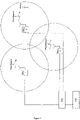
- FIG. 1 depicts a basic structure and provides an example of a Flexible Simulcast downlink transport scenario.
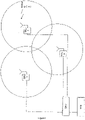
- Figure 2 depicts an embodiment of a basic structure of a Flexible Simulcast uplink transport scenario.
- an embodiment converts only that plurality of specific, relatively narrow bandwidths that carry useful information.
- this aspect of the present invention allows more efficient use of the available optical fiber transport bandwidth for neutral host applications, and facilitates transport of more operators' band segments over the optical fiber.
- the present invention utilizes frequency-selective filtering at the Remote Radio Head which enhances the system performance.
- noise reduction via frequency- selective filtering at the Remote Radio Head is utilized for maximizing the SNR and consequently maximizing the data throughput.
- It is a further object of the present invention to provide CDMA and WCDMA indoor location accuracy enhancement.
- an embodiment provides enhanced location accuracy performance by employing pilot beacons.
- Figure 3 depicts a typical indoor system employing multiple Remote Radio Head Units (RRUs) and a central Digital Access Unit (DAU).
- the Remote Radio Heads have a unique beacon that is distinct and identifies that particular indoor cell. The mobile user will use the beacon information to assist in the localization to a particular cell..
- an embodiment of the present invention provides localization of a user based on the radio signature of the mobile device.
- Figure 4 depicts a typical indoor system employing multiple Remote Radio Head Units (RRUs) and a central Digital Access Unit (DAU).
- RRUs Remote Radio Head Units
- DAU Digital Access Unit
- each Remote Radio Head provides unique header information on data received by that Remote Radio Head.
- the system of the invention uses this header information in conjunction with the mobile user's radio signature to localize the user to a particular cell. It is a further object of the present invention to re-route local traffic to Internet VOIP, Wi-Fi or WiMAX.
- an embodiment determines the radio signatures of the individual users within a DAU or Island of DAUs and uses this information to identify if the users are located within the coverage area associated with a specific DAU or Island of DAUs.
- the DAUs track the radio signatures of all the active users within its network and record a running data base containing information pertaining to them.
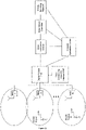
- One embodiment of the present invention is for the Network Operations Center (NOC) to inform the DAU that, e.g., two specific users are collocated within the same DAU or Island of DAUs, as depicted in Figure 6 .
- the DAUs then reroute the users to Internet VOIP, Wi-Fi or WiMAX as appropriate.
- Another embodiment of the present invention is to determine the Internet Protocol (IP) addresses of the individual users' Wi-Fi connections. If the individual users' IP addresses are within the same DAU or Island of DAUs, the data call for these users is rerouted over the internal network.
- IP Internet Protocol
- Applications of the present invention are suitable to be employed with distributed base stations, distributed antenna systems, distributed repeaters, mobile equipment and wireless terminals, portable wireless devices, and other wireless communication systems such as microwave and satellite communications.
- the present invention is also field upgradable through a link such as an Ethernet connection to a remote computing center.
- the present invention is a novel Reconfigurable Distributed Antenna System that provides a high degree of flexibility to manage, control, re-configure, enhance and facilitate the radio resource efficiency, usage and overall performance of the distributed wireless network.
- An embodiment of the Reconfigurable Distributed Antenna System in accordance with the present invention is shown in Figure 1 .
- the Flexible Simulcast System 100 can be used to explain the operation of Flexible Simulcast with regard to downlink signals.
- the system employs a Digital Access Unit functionality (hereinafter "DAU").
- the DAU serves as an interface to the base station (BTS).
- the DAU is (at one end) connected to the BTS, and on the other side connected to multiple RRUs.
- RF signals received from the BTS are separately down-converted, digitized, and converted to baseband (using a Digital Down-Converter). Data streams are then I/Q mapped and framed. Specific parallel data streams are then independently serialized and translated to optical signals using pluggable SFP modules, and delivered to different RRUs over optical fiber cable.
- optical signals received from RRUs are deserialized, deframed, and up-converted digitally using a Digital Up-Converter. Data streams are then independently converted to the analog domain and up-converted to the appropriate RF frequency band. The RF signal is then delivered to the BTS.
- An embodiment of the system is mainly comprised of DAU1 indicated at 101, RRU1 indicated at 103, RRU2 indicated at 104, DAU2 indicated at 102, RRU3 indicated at 105, and RRU4 indicated at 106.
- Composite signal 107 is comprised of Carriers 1-4.
- a second composite downlink input signal from e.g., a second base station belonging to the same wireless operator enters DAU2 at the DAU2 RF input port.
- Composite signal 108 is comprised of Carriers 5-8.
- DAU1, DAU2, RRU1, RRU2, RRU3 and RRU4 are explained in detail by U.S. Provisional Application S.N. 61/374593, entitled “Neutral Host Architecture for a Distributed Antenna System,” filed August 17, 2010 and attached hereto as an appendix.
- One optical output of DAU1 is fed to RRU1.
- a second optical output of DAU1 is fed via bidirectional optical cable 113 to DAU2. This connection facilitates networking of DAU1 and DAU2, which means that all of Carriers 1-8 are available within DAU1 and DAU2 to transport to RRU1, RRU2, RRU3 and RRU4 depending on software settings within the networked DAU system comprised of DAU1 and DAU2.
- RRU1 The software settings within RRU1 are configured either manually or automatically such that Carriers 1-8 are present in the downlink output signal 109 at the antenna port of RRU1.
- the presence of all 8 carriers means that RRU1 is potentially able to access the full capacity of both base stations feeding DAU1 and DAU2.
- a possible application for RRU1 is in a wireless distribution system is e.g., a cafeteria in an enterprise building during the lunch hour where a large number of wireless subscribers are gathered.
- RRU2 is fed by a second optical port of RRU1 via bidirectional optical cable 114 to RRU2.
- Optical cable 114 performs the function of daisy chaining RRU2 with RRU1.
- the software settings within RRU2 are configured either manually or automatically such that Carriers 1, 3, 4 and 6 are present in downlink output signal 110 at the antenna port of RRU2.
- the capacity of RRU2 is set to a much lower value than RRU1 by virtue of its specific Digital Up Converter settings.
- the individual Remote Radio Units have integrated frequency selective DUCs and DDCs with gain control for each carrier. The DAUs can remotely turn on and off the individual carriers via the gain control parameters.
- the software settings within RRU3 are configured either manually or automatically such that Carriers 2 and 6 are present in downlink output signal 111 at the antenna port of RRU3.
- the capacity of RRU3 which is configured via the software settings of RRU3 is much less than the capacity of RRU2.
- RRU4 is fed by a second optical port of RRU3 via bidirectional optical cable 115 to RRU4.
- Optical cable 115 performs the function of daisy chaining RRU4 with RRU3.
- the software settings within RRU4 are configured either manually or automatically such that Carriers 1, 4, 5 and 8 are present in downlink output signal 112 at the antenna port of RRU4.
- RRU4 The capacity of RRU4 is set to a much lower value than RRU1.
- the present invention facilitates conversion and transport of several discrete relatively narrow RF bandwidths. This approach allows conversion of only those multiple specific relatively narrow bandwidths which carry useful or specific information. This approach also allows more efficient use of the available optical fiber transport bandwidth for neutral host applications, and allows transport of more individual operators' band segments over the optical fiber. As disclosed in U.S. Provisional Application S.N.
- a related capability of the present invention is that not only can the Digital Up Converters located within each RRU be configured to transport any specific narrow frequency band from the DAU input to any specific RRU output, but also the Digital Up Converters within each RRU can be configured to transport any specific time slot or time slots of each carrier from the DAU input to any specific RRU output.
- the DAU detects which carriers and corresponding time slots are active. This information is relayed to the individual RRUs via the management control and monitoring protocol software discussed hereinafter. This information is then used, as appropriate, by the RRUs for turning off and on individual carriers and their corresponding time slots.
- an alternative embodiment of the present invention may be described as follows.
- a previous embodiment involved having downlink signals from two separate base stations belonging to the same wireless operator enter DAU1 and DAU2 input ports respectively.
- a second composite downlink input signal from e.g., a second base station belonging to a different wireless operator enters DAU2 at the DAU2 RF input port.
- signals belonging to both the first operator and the second operator are converted and transported to RRU1, RRU2, RRU3 and RRU4 respectively.
- This embodiment provides an example of a neutral host wireless system, where multiple wireless operators share a common infrastructure comprised of DAU1, DAU2, RRU1, RRU2, RRU3 and RRU4. All the previously mentioned features and advantages accrue to each of the two wireless operators.
- the Digital Up Converters present in the RRU can be programmed to process various signal formats and modulation types including FDMA, CDMA, TDMA, OFDMA and others. Also, the Digital Up Converters present in the respective RRUs can be programmed to operate with signals to be transmitted within various frequency bands subject to the capabilities and limitations of the system architecture disclosed in U.S. Provisional Application S.N. 61/374593, entitled “Neutral Host Architecture for a Distributed Antenna System,” filed August 17, 2010 .
- the transmitted signal at the antenna ports of RRU1, RRU2 and RRU4 will be a wideband CDMA signal which is virtually identical to the signal present within the bandwidth corresponding to carrier 1 at the input port to DAU1.
- the Digital Up Converters present in the respective RRUs can be programmed to transmit any desired composite signal format to each of the respective RRU antenna ports.
- the Digital Up Converters present in RRU1 and RRU2 can be dynamically software-reconfigured as described previously so that the signal present at the antenna port of RRU1 would correspond to the spectral profile shown in Figure 1 as 110, and also that the signal present at the antenna port of RRU2 would correspond to the spectral profile shown in Figure 1 as 109.
- FIG. 2 Another embodiment of the Distributed Antenna System in accordance with the present invention is shown in Figure 2 .
- the Flexible Simulcast System 200 can be used to explain the operation of Flexible Simulcast with regard to uplink signals.
- the uplink system shown in Figure 2 is mainly comprised of DAU1 indicated at 201, RRU1 indicated at 203, RRU2 indicated at 204, DAU2 indicated at 202, RRU3 indicated at 205, and RRU4 indicated at 206.
- the operation of the uplink system shown in Figure 2 can be understood as follows.
- the Digital Down Converters present in each of RRU1, RRU2, RRU3 and RRU4 are dynamically software-configured as described previously so that uplink signals of the appropriate desired signal format(s) present at the receive antenna ports of the respective RRU1, RRU2, RRU3 and RRU4 are selected based on the desired uplink band(s) to be processed and filtered, converted and transported to the appropriate uplink output port of either DAU1 or DAU2.
- the DAUs and RRUs frame the individual data packets corresponding to their respective radio signature using the Common Public Interface Standard (CPRI). Other Interface standards are applicable provided they uniquely identify data packets with respective RRUs. Header information is transmitted along with the data packet which indentifies the RRU and DAU that corresponds to the individual data packet.
- CPRI Common Public Interface Standard
- RRU1 and RRU3 are configured to receive uplink signals within the Carrier 2 bandwidth, whereas RRU2 and RRU4 are both configured to reject uplink signals within the Carrier 2 bandwidth.
- RRU3 receives a strong enough signal at its receive antenna port within the Carrier 2 bandwidth to be properly filtered and processed
- the Digital Down Converters within RRU3 facilitate processing and conversion.
- RRU1 and RRU3 receives a strong enough signal at its receive antenna port within the Carrier 2 bandwidth to be properly filtered and processed
- the Digital Down Converters within RRU1 facilitate processing and conversion.
- the signals from RRU1 and RRU3 are combined based on the active signal combining algorithm, and are fed to the base station connected to the uplink output port of DAU1.
- simulcast is frequently used to describe the operation of RRU1 and RRU3 with regard to uplink and downlink signals within Carrier 2 bandwidth.
- Flexible Simulcast refers to the fact that the present invention supports dynamic and/or manual rearrangement of which specific RRU are involved in the signal combining process for each Carrier bandwidth.
- the Digital Down Converters present in RRU1 are configured to receive and process signals within Carrier 1-8 bandwidths.
- the Digital Down Converters present in RRU2 are configured to receive and process signals within Carrier 1, 3, 4 and 6 bandwidths.
- the Digital Down Converters present in RRU3 are configured to receive and process signals within Carrier 2 and 6 bandwidths.
- the Digital Down Converters present in RRU4 are configured to receive and process signals within Carrier 1, 4, 5 and 8 bandwidths.
- the respective high-speed digital signals resulting from processing performed within each of the four RRU are routed to the two DAUs. As described previously, the uplink signals from the four RRUs are combined within the respective DAU corresponding to each base station.
- An aspect of the present invention includes an integrated Pilot Beacon function within the each RRU.
- each RRU comprises a unique software programmable Pilot Beacon as discussed hereinafter This approach is intended for use in CDMA and/or WCDMA indoor DAS networks. A very similar approach can be effective for indoor location accuracy enhancement for other types of networks such as LTE and WiMAX. Because each RRU is already controlled and monitored via the DAUs which comprise the network, there is no need for costly deployment of additional dedicated wireless modems for remote monitoring and control of pilot beacons.
- Each operational pilot beacon function within an RRU employs a unique PN code (in that area) which effectively divides the WCDMA or CDMA indoor network coverage area into multiple small "zones" (which each correspond to the coverage area of a low-power Pilot Beacon).
- Each Pilot Beacon's location, PN code and RF Power level are known by the network.
- Each Pilot Beacon is synchronized to the WCDMA or CDMA network, via its connection to the DAU.
- the Pilot Beacon transmit signal will be effectively “static” and its downlink messages will not change over time based on network conditions.
- each mobile subscriber terminal in Idle mode is able to perform Pilot Signal measurements of downlink signals transmitted by base stations and Pilot Beacons.
- the WCDMA mobile subscriber terminal transitions to Active mode, it reports to the serving cell all its Pilot Signal measurements for base stations and for Pilot Beacons.
- the operation is very similar.
- the RRU can be provisioned as either a Pilot Beacon or to serve mobile subscribers in a particular operator bandwidth, but not both.
- CPICH RSCP Peak Signal Code Power
- measurements of CPICH Ec/No by the mobile subscriber terminal in either Idle mode or any of several active modes are possible.
- the mobile subscriber terminal reports all available RSCP and Ec/No measurements via the serving base station (whether indoor or outdoor) to the network. Based on that information, the most likely mobile subscriber terminal location is calculated and/or determined.
- CPICH RSCP Peak Signal Code Power
- the operation is very similar to the process described herein.
- a previously described embodiment of the present invention referring to Figure 1 involved having a wideband CDMA signal present within e.g., the bandwidth corresponding to carrier 1 at the input port to DAU1.
- the transmitted signal at the antenna ports of RRU1, RRU2 and RRU4 is a wideband CDMA signal which is virtually identical to the signal present within the bandwidth corresponding to carrier 1 at the input port to DAU1.
- An alternative embodiment of the present invention is one where a wideband CDMA signal is present within e.g., the bandwidth corresponding to carrier 1 at the input port to DAU1.
- the transmitted signal at the antenna port of RRU1 differs slightly from the previous embodiment.
- a wideband CDMA signal is present within e.g., the bandwidth corresponding to carrier 1 at the input port to DAU1.
- the transmitted signal from RRU1 is a combination of the wideband CDMA signal which was present at the input port to DAU1, along with a specialized WCDMA pilot beacon signal.
- the WCDMA pilot beacon signal is intentionally set well below the level of the base station pilot signal.
- the transmitted signal at the antenna port of RRU1 is a combination of the CDMA signal which was present at the input port to DAU1, along with a specialized CDMA pilot beacon signal.
- the CDMA pilot beacon signal is intentionally set well below the level of the base station pilot signal.
- FIG. 4 depicts a typical indoor system employing multiple Remote Radio Head Units (RRUs) and a central Digital Access Unit (DAU).
- RRUs Remote Radio Head Units
- DAU Digital Access Unit
- Each Remote Radio Head provides a unique header information on data received by that Remote Radio Head. This header information in conjunction with the mobile user's radio signature are used to localize the user to a particular cell.
- the DAU signal processing can identify the individual carriers and their corresponding time slots.
- a header is included with each data packet that uniquely identifies the corresponding RRU.
- the DAU can detect the carrier frequency and the corresponding time slot associated with the individual RRUs.
- the DAU has a running data base that identifies each carrier frequency and time slot with a respective RRU.
- the carrier frequency and time slot is the radio signature that uniquely identifies the GSM user.
- the DAU communicates with a Network Operation Center (NOC) via a Ethernet connection or an external modem, as depicted in Figure 5 .
- NOC Network Operation Center
- MSC Mobile Switching Center
- BTS BaseTransceiver Station
- the NOC then makes a request to the individual DAUs to determine if the E911 radio signature is active in their indoor cell.
- the DAU checks its data base for the active carrier frequency and time slot. If that radio signature is active in the DAU, then that DAU will provide the NOC with the location information of the corresponding RRU.
- a further embodiment of the present invention includes LTE to provide enhanced accuracy for determining the location of indoor wireless subscribers.
- GSM uses individual carriers and time slots to distinguish users whereas LTE uses multiple carriers and time slot information to distinguish users.
- the DAU can simultaneously detect multiple carriers and their corresponding time slots to uniquely identify the LTE user.
- the DAU has a running data base that identifies the carrier frequencies and time slot radio signature for the respective RRU. This information can be retrieved from the NOC once a request is made to the DAU.
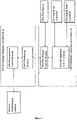
- the DAU embedded software control module and RRU embedded software control module can be better understood in connection with the operation of key functions of the DAU and RRU.
- One such key function is determining and/or setting the appropriate amount of radio resources (such as RF carriers, CDMA codes or TDMA time slots) assigned to a particular RRU or group of RRUs to meet desired capacity and throughput objectives.
- the DAU embedded software control module comprises a DAU Monitoring module that detects which carriers and corresponding time slots are active for each RRU.
- the DAU embedded software control module also comprises a DAU Management Control module which communicates with the RRU over a fiber optic link control channel via a control protocol with the RRU Management Control module.
- the RRU Management Control module sets the individual parameters of all the RRU Digital Up-Converters to enable or disable specific radio resources from being transmitted by a particular RRU or group of RRUs, and also sets the individual parameters of all the RRU Digital Down-Converters to enable or disable specific uplink radio resources from being processed by a particular RRU or group of RRUs.
- an algorithm operating within the DAU Monitoring module that detects which carriers and corresponding time slots for each carrier are active for each RRU, provides information to the DAU Management Control module to help identify when, e.g., a particular downlink carrier is loaded by a percentage greater than a predetermined threshold whose value is communicated to the DAU Management Control module by the DAU's Remote Monitoring and Control function. If that occurs, the DAU Management Control module adaptively modifies the system configuration to slowly begin to deploy additional radio resources (such as RF carriers, CDMA codes or TDMA time slots) for use by a particular RRU which need those radio resources within its coverage area.
- additional radio resources such as RF carriers, CDMA codes or TDMA time slots
- the DAU Management Control module adaptively modifies the system configuration to slowly begin to remove certain radio resources (such as RF carriers, CDMA codes or TDMA time slots) for use by a particular RRU which no longer needs those radio resources within its coverage area.
- Another such key function of the DAU embedded software control module and RRU embedded software control module is determining and/or setting and/or analyzing the appropriate transmission parameters and monitoring parameters for the integrated Pilot Beacon function contained within each RRU.
- Pilot Beacon transmission and monitoring parameters include Beacon Enable/Disable, Beacon Carrier Frequencies, Beacon Transmit Power, Beacon PN Code, Beacon Downlink BCH Message Content, Beacon Alarm, Beacon Delay Setting and Beacon Delay Adjustment Resolution.
- the RRU Pilot Beacon Control module communicates with the pilot beacon generator function in the RRU to set and monitor the pilot beacon parameters as listed herein.
- the Reconfigurable Distributed Antenna System of the present invention described herein efficiently conserves resources and reduces costs.
- the reconfigurable system is adaptive or manually field-programmable, since the algorithms can be adjusted like software in the digital processor at any time.
Abstract
Description
- This application claims the benefit of the following U.S. Patent applications, all of which are incorporated herein by reference:
Serial Number Filinq Date Title 61/374,593 8/17/2010 Neutral Host Architecture for a Distributed Antenna System 61/382,836 9/14/2010 Remotely Reconfigurable Distributed Antenna System and Methods 12/928,931 12/21/2010 Modulation Agnostic Digital Hybrid Mode Power Amplifier System and Method 12/928,933 12/21/2010 Remote Radio Head Unit System with Wideband Power Amplifier and Method 12/928,934 12/21/2010 Multi-Band Wideband Power Amplifier Digital Predistortion System and Method 12/928,943 12/21/2010 High Efficiency, Remotely Reconfigurable Remote Radio Head Unit System and Method for Wireless Communications 61/439,940 2/7/2011 Daisy Chained Ring of Remote Units for a Distributed Antenna System - The present invention generally relates to wireless communication systems employing Distributed Antenna Systems (DAS) as part of a distributed wireless network. More specifically, the present invention relates to a DAS utilizing software defined radio (SDR).
- Wireless and mobile network operators face the continuing challenge of building networks that effectively manage high data-traffic growth rates. Mobility and an increased level of multimedia content for end users requires end-to-end network adaptations that support both new services and the increased demand for broadband and flat-rate Internet access. One of the most difficult challenges faced by network operators is caused by the physical movement of subscribers from one location to another, and particularly when wireless subscribers congregate in large numbers at one location. A notable example is a business enterprise facility during lunchtime, when a large number of wireless subscribers visit a cafeteria location in the building. At that time, a large number of subscribers have moved away from their offices and usual work areas. It's likely that during lunchtime there are many locations throughout the facility where there are very few subscribers. If the indoor wireless network resources were properly sized during the design process for subscriber loading as it is during normal working hours when subscribers are in their normal work areas, it is very likely that the lunchtime scenario will present some unexpected challenges with regard to available wireless capacity and data throughput.
- To accommodate this variation in subscriber loading, there are several candidate prior art approaches.
- One approach is to deploy many low-power high-capacity base stations throughout the facility. The quantity of base stations is determined based on the coverage of each base station and the total space to be covered. Each of these base stations is provisioned with enough radio resources, i.e., capacity and broadband data throughput to accommodate the maximum subscriber loading which occurs during the course of the workday and work week. Although this approach typically yields a high quality of service, the notable disadvantage of this approach is that during a major part of the time many of the base stations' capacity is being wasted. Since a typical indoor wireless network deployment involves capital and operational costs which are assessed on a per-subscriber basis for each base station, the typically high total life cycle cost for a given enterprise facility is far from optimal.
- A second candidate approach involves deployment of a DAS along with a centralized group of base stations dedicated to the DAS. A conventional DAS deployment falls into one of two categories. The first type of DAS is "fixed", where the system configuration doesn't change based on time of day or other information about usage. The remote units associated with the DAS are set up during the design process so that a particular block of base station radio resources is thought to be enough to serve each small group of DAS remote units. A notable disadvantage of this approach is that most enterprises seem to undergo frequent re-arrangements and re-organizations of various groups within the enterprise. Therefore, it's highly likely that the initial setup will need to be changed from time to time, requiring deployment of additional staff and contract resources with appropriate levels of expertise regarding wireless networks.
- The second type of DAS is equipped with a type of network switch which allows the location and quantity of DAS remote units associated with any particular centralized base station to be changed manually. Although this approach would seem to allow dynamic reconfiguration based on the needs of the enterprise or based on time of day, it frequently requires deployment of additional staff resources for real-time management of the network. Another issue is that it's not always correct or best to make the same DAS remote unit configuration changes back and forth on each day of the week at the same times of day. Frequently it is difficult or impractical for an enterprise IT manager to monitor the subscriber loading on each base station. And it is almost certain that the enterprise IT manager has no practical way to determine the loading at a given time of day for each DAS remote unit; they can only guess.
- Another major limitation of prior art DAS deployments is related to their installation, commissioning and optimization process. Some challenging issues which must be overcome include selecting remote unit antenna locations to ensure proper coverage while minimizing downlink interference from outdoor macro cell sites, minimizing uplink interference to outdoor macro cell sites, and ensuring proper intra-system handovers while indoors and while moving from outdoors to indoors (and vice-versa). The process of performing such deployment optimization is frequently characterized as trial-and-error and as such, the results may not be consistent with a high quality of service.
- A major limitation of prior art DAS equipment employing digital transmission links such as optical fiber or wired Ethernet is the fact that the prior-art RF-to-digital conversion techniques utilize an approach whereby the system converts a single broad RF bandwidth of e.g., 10 to 25 MHz to digital. Therefore all the signals, whether weak or strong, desired or undesired, contained within that broad bandwidth are converted to digital, whether those signals are desired or not. This approach frequently leads to inefficiencies within the DAS which limit the DAS network capacity. It would be preferable to employ an alternative approach yielding greater efficiencies and improved flexibility, particularly for neutral host applications.
- In 2008 the FCC further clarified its E-911 requirements with regard to
Phase 2 accuracy for mobile wireless networks. The information required inPhase 2 is the mobile phone number and the physical location, within a few dozen yards, from which the call was made. The Canadian government is reportedly considering enacting similar requirements. Also the FCC is eager to see US mobile network operators provide positioning services with enhanced accuracy for E-911 for indoor subscribers. There is a reported effort within the FCC to try to mandatePhase 2 accuracy indoors, within the next 2 years. - Many wireless networks employ mobile and fixed broadband wireless terminals which employ GPS-based E-911 location services. It has been demonstrated that GPS signals from satellites outdoors don't propagate well into the indoor space. Therefore an alternative, more robust E-911 location determination approach is required for indoors, particularly if the FCC requirements are changed to be more stringent.
- Several US operators have expressed concern about how they can practically and cost-effectively obtain these enhanced location accuracy capabilities. Operators are very eager to identify a cost-effective approach which can be deployed indoors for enhanced location accuracy.
- One proposed approach toward indoor location accuracy enhancement for CDMA networks would employ a separate unit known as a CDMA Pilot Beacon. A notable disadvantage of this approach for an indoor DAS application is that since the CDMA Pilot Beacon unit is a separate and dedicated device and not integrated within the DAS, it would likely be costly to deploy. The Pilot Beacon approach for CDMA networks employs a Pilot Beacon with a unique PN code (in that area) which effectively divides a particular CDMA network coverage area (e.g., indoors) into multiple small zones (which each correspond to the coverage area of a low-power Pilot Beacon). Each Pilot Beacon's location, PN code and RF Power level are known by the network. Each Pilot Beacon must be synchronized to the CDMA network, via GPS or local base station connection. A variable delay setting permits each Pilot Beacon to have the appropriate system timing to permit triangulation and/or Cell ID position determination. One optional but potentially costly enhancement to this approach would employ a Wireless Modem for each Pilot Beacon to provide remote Alarms, Control and Monitoring of each CDMA Pilot Beacon. No known solution for indoor location accuracy enhancement has been publicly proposed for WCDMA networks.
- One candidate technically-proven approach toward indoor location accuracy enhancement for GSM networks would employ a separate unit known as a Location Measurement Unit or LMU. A notable disadvantage of this approach for an indoor DAS application is that, since the LMU is a separate and dedicated device and not integrated within the DAS, it is costly to deploy. Each LMU requires a backhaul facility to a central server which analyzes the LMU measurements. The LMU backhaul cost adds to the total cost of deploying the enhanced accuracy E-911 solution for GSM networks. Despite the availability of the already technically-proven LMU approach, it has not been widely deployed in conjunction with indoor DAS.
- Based on the prior art approaches described herein, it is apparent that a highly efficient, easily deployed and dynamically reconfigurable wireless network is not achievable with prior art systems and capabilities.
- The present invention substantially overcomes the limitations of the prior art discussed above. The advanced system architecture of the present invention provides a high degree of flexibility to manage, control, enhance and facilitate radio resource efficiency, usage and overall performance of the distributed wireless network. This advanced system architecture enables specialized applications and enhancements including flexible simulcast, automatic traffic load-balancing, network and radio resource optimization, network calibration, autonomous/assisted commissioning, carrier pooling, automatic frequency selection, radio frequency carrier placement, traffic monitoring, traffic tagging, and indoor location determination using pilot beacons. The present invention can also serve multiple operators, multi-mode radios (modulation-independent) and multi-frequency bands per operator to increase the efficiency and traffic capacity of the operators' wireless networks.
- Accordingly, it is an object of the present invention to provide a capability for Flexible Simulcast. With Flexible Simulcast, the amount of radio resources (such as RF carriers, CDMA codes or TDMA time slots) assigned to a particular RRU or group of RRUs by each RRU Access Module can be set via software control as described hereinafter to meet desired capacity and throughput objectives or wireless subscriber needs. To achieve these and other objects, an aspect of the present invention employs software-programmable frequency selective Digital Up-Converters (DUCs) and Digital Down-Converters (DDCs). A software-defined Remote Radio Head architecture is used for cost-effective optimization of the radio performance. Frequency selective DDCs and DUCs at the Remote Radio Head enable a high signal to noise ratio (SNR) which maximize the throughput data rate. An embodiment shown in
Figure 1 depicts a basic structure and provides an example of a Flexible Simulcast downlink transport scenario.Figure 2 depicts an embodiment of a basic structure of a Flexible Simulcast uplink transport scenario. - It is a further object of the present invention to facilitate conversion and transport of several discrete relatively narrow RF bandwidths. In another aspect of the invention, an embodiment converts only that plurality of specific, relatively narrow bandwidths that carry useful information. Thus, this aspect of the present invention allows more efficient use of the available optical fiber transport bandwidth for neutral host applications, and facilitates transport of more operators' band segments over the optical fiber. To achieve the above result, the present invention utilizes frequency-selective filtering at the Remote Radio Head which enhances the system performance. In some embodiments of this aspect of the invention, noise reduction via frequency- selective filtering at the Remote Radio Head is utilized for maximizing the SNR and consequently maximizing the data throughput. It is a further object of the present invention to provide CDMA and WCDMA indoor location accuracy enhancement. In an aspect of the present invention, an embodiment provides enhanced location accuracy performance by employing pilot beacons.
Figure 3 depicts a typical indoor system employing multiple Remote Radio Head Units (RRUs) and a central Digital Access Unit (DAU). The Remote Radio Heads have a unique beacon that is distinct and identifies that particular indoor cell. The mobile user will use the beacon information to assist in the localization to a particular cell.. - It is a further object of the present invention to enhance GSM and LTE indoor location accuracy.. In another aspect, an embodiment of the present invention provides localization of a user based on the radio signature of the mobile device.
Figure 4 depicts a typical indoor system employing multiple Remote Radio Head Units (RRUs) and a central Digital Access Unit (DAU). In accordance with the invention, each Remote Radio Head provides unique header information on data received by that Remote Radio Head. The system of the invention uses this header information in conjunction with the mobile user's radio signature to localize the user to a particular cell. It is a further object of the present invention to re-route local traffic to Internet VOIP, Wi-Fi or WiMAX. In this aspect of the invention, an embodiment determines the radio signatures of the individual users within a DAU or Island of DAUs and uses this information to identify if the users are located within the coverage area associated with a specific DAU or Island of DAUs. The DAUs track the radio signatures of all the active users within its network and record a running data base containing information pertaining to them. One embodiment of the present invention is for the Network Operations Center (NOC) to inform the DAU that, e.g., two specific users are collocated within the same DAU or Island of DAUs, as depicted inFigure 6 . The DAUs then reroute the users to Internet VOIP, Wi-Fi or WiMAX as appropriate. Another embodiment of the present invention is to determine the Internet Protocol (IP) addresses of the individual users' Wi-Fi connections. If the individual users' IP addresses are within the same DAU or Island of DAUs, the data call for these users is rerouted over the internal network. - Applications of the present invention are suitable to be employed with distributed base stations, distributed antenna systems, distributed repeaters, mobile equipment and wireless terminals, portable wireless devices, and other wireless communication systems such as microwave and satellite communications. The present invention is also field upgradable through a link such as an Ethernet connection to a remote computing center.
- Appendix I is a glossary of terms used herein, including acronyms.
- Further objects and advantages of the present invention can be more fully understood from the following detailed description taken in conjunction with the accompanying drawings in which:
-
Figure 1 is a block diagram according to one embodiment of the invention showing the basic structure and an example of a Flexible Simulcast downlink transport scenario based on having 2 DAU and 4 DRU. -
Figure 2 is a block diagram in accordance with an embodiment of the invention showing the basic structure and an example of a Flexible Simulcast uplink transport scenario based on having 2 DAU and 4 DRU. -
Figure 3 shows an embodiment of an indoor system employing multiple Remote Radio Head Units (RRUs) and a central Digital Access Unit (DAU). -
Figure 4 shows an embodiment of an indoor system in accordance with the invention which employs multiple Remote Radio Head Units (RRUs) and a central Digital Access Unit (DAU). -
Figure 5 illustrates an embodiment of a cellular network system employing multiple Remote Radio Heads according to the present invention. -
Figure 6 is a depiction of local connectivity according to one embodiment of the present invention. -
Figure 7 illustrates an embodiment of the basic structure of the embedded software control modules which manage key functions of the DAU and RRU, in accordance with the present invention. - The present invention is a novel Reconfigurable Distributed Antenna System that provides a high degree of flexibility to manage, control, re-configure, enhance and facilitate the radio resource efficiency, usage and overall performance of the distributed wireless network. An embodiment of the Reconfigurable Distributed Antenna System in accordance with the present invention is shown in
Figure 1 . TheFlexible Simulcast System 100 can be used to explain the operation of Flexible Simulcast with regard to downlink signals. The system employs a Digital Access Unit functionality (hereinafter "DAU"). The DAU serves as an interface to the base station (BTS). The DAU is (at one end) connected to the BTS, and on the other side connected to multiple RRUs. For the downlink (DL) path, RF signals received from the BTS are separately down-converted, digitized, and converted to baseband (using a Digital Down-Converter). Data streams are then I/Q mapped and framed. Specific parallel data streams are then independently serialized and translated to optical signals using pluggable SFP modules, and delivered to different RRUs over optical fiber cable. For the uplink (UL) path optical signals received from RRUs are deserialized, deframed, and up-converted digitally using a Digital Up-Converter. Data streams are then independently converted to the analog domain and up-converted to the appropriate RF frequency band. The RF signal is then delivered to the BTS. An embodiment of the system is mainly comprised of DAU1 indicated at 101, RRU1 indicated at 103, RRU2 indicated at 104, DAU2 indicated at 102, RRU3 indicated at 105, and RRU4 indicated at 106. A compositedownlink input signal 107 from, e.g., a base station belonging to one wireless operator enters DAU1 at the DAU1 RF input port.Composite signal 107 is comprised of Carriers 1-4. A second composite downlink input signal from e.g., a second base station belonging to the same wireless operator enters DAU2 at the DAU2 RF input port.Composite signal 108 is comprised of Carriers 5-8. The functionality of DAU1, DAU2, RRU1, RRU2, RRU3 and RRU4 are explained in detail byU.S. Provisional Application S.N. 61/374593, entitled "Neutral Host Architecture for a Distributed Antenna System," filed August 17, 2010 optical cable 113 to DAU2. This connection facilitates networking of DAU1 and DAU2, which means that all of Carriers 1-8 are available within DAU1 and DAU2 to transport to RRU1, RRU2, RRU3 and RRU4 depending on software settings within the networked DAU system comprised of DAU1 and DAU2. The software settings within RRU1 are configured either manually or automatically such that Carriers 1-8 are present in thedownlink output signal 109 at the antenna port of RRU1. The presence of all 8 carriers means that RRU1 is potentially able to access the full capacity of both base stations feeding DAU1 and DAU2. A possible application for RRU1 is in a wireless distribution system is e.g., a cafeteria in an enterprise building during the lunch hour where a large number of wireless subscribers are gathered. RRU2 is fed by a second optical port of RRU1 via bidirectionaloptical cable 114 to RRU2.Optical cable 114 performs the function of daisy chaining RRU2 with RRU1. The software settings within RRU2 are configured either manually or automatically such thatCarriers downlink output signal 110 at the antenna port of RRU2. The capacity of RRU2 is set to a much lower value than RRU1 by virtue of its specific Digital Up Converter settings. The individual Remote Radio Units have integrated frequency selective DUCs and DDCs with gain control for each carrier. The DAUs can remotely turn on and off the individual carriers via the gain control parameters. - In a similar manner as described previously for RRU1, the software settings within RRU3 are configured either manually or automatically such that
Carriers downlink output signal 111 at the antenna port of RRU3. Compared to thedownlink signal 110 at the antenna port of RRU2, the capacity of RRU3 which is configured via the software settings of RRU3 is much less than the capacity of RRU2. RRU4 is fed by a second optical port of RRU3 via bidirectionaloptical cable 115 to RRU4.Optical cable 115 performs the function of daisy chaining RRU4 with RRU3. The software settings within RRU4 are configured either manually or automatically such thatCarriers downlink output signal 112 at the antenna port of RRU4. The capacity of RRU4 is set to a much lower value than RRU1. The relative capacity settings of RRU1, RRU2, RRU3 and RRU4 and can be adjusted dynamically as discussed in connection withFigure 7 to meet the capacity needs within the coverage zones determined by the physical positions of antennas connected to RRU1, RRU2, RRU3 and RRU4 respectively. - The present invention facilitates conversion and transport of several discrete relatively narrow RF bandwidths. This approach allows conversion of only those multiple specific relatively narrow bandwidths which carry useful or specific information. This approach also allows more efficient use of the available optical fiber transport bandwidth for neutral host applications, and allows transport of more individual operators' band segments over the optical fiber. As disclosed in
U.S. Provisional Application S.N. 61/374593, entitled "Neutral Host Architecture for a Distributed Antenna System," filed August 17, 2010 Figure 1 of the instant patent application, Digital Up Converters located within the RRU which are dynamically software-programmable as discussed hereinafter can be re-configured to transport from the DAU input to any specific RRU output any specific narrow frequency band or bands, RF carriers or RF channels which are available at the respective RF input port of either DAU. This capability is illustrated inFigure 1 where only specific frequency bands or RF carriers appear at the output of a given RRU. - A related capability of the present invention is that not only can the Digital Up Converters located within each RRU be configured to transport any specific narrow frequency band from the DAU input to any specific RRU output, but also the Digital Up Converters within each RRU can be configured to transport any specific time slot or time slots of each carrier from the DAU input to any specific RRU output. The DAU detects which carriers and corresponding time slots are active. This information is relayed to the individual RRUs via the management control and monitoring protocol software discussed hereinafter. This information is then used, as appropriate, by the RRUs for turning off and on individual carriers and their corresponding time slots.
- Referring to
Figure 1 of the instant patent application, an alternative embodiment of the present invention may be described as follows. In a previous description ofFigure 1 , a previous embodiment involved having downlink signals from two separate base stations belonging to the same wireless operator enter DAU1 and DAU2 input ports respectively. In an alternative embodiment, a second composite downlink input signal from e.g., a second base station belonging to a different wireless operator enters DAU2 at the DAU2 RF input port. In this embodiment, signals belonging to both the first operator and the second operator are converted and transported to RRU1, RRU2, RRU3 and RRU4 respectively. This embodiment provides an example of a neutral host wireless system, where multiple wireless operators share a common infrastructure comprised of DAU1, DAU2, RRU1, RRU2, RRU3 and RRU4. All the previously mentioned features and advantages accrue to each of the two wireless operators. - As disclosed in
U.S. Provisional Application S.N. 61/374593, entitled "Neutral Host Architecture for a Distributed Antenna System," filed August 17, 2010 Figure 1 of the instant patent application, the Digital Up Converters present in the RRU can be programmed to process various signal formats and modulation types including FDMA, CDMA, TDMA, OFDMA and others. Also, the Digital Up Converters present in the respective RRUs can be programmed to operate with signals to be transmitted within various frequency bands subject to the capabilities and limitations of the system architecture disclosed inU.S. Provisional Application S.N. 61/374593, entitled "Neutral Host Architecture for a Distributed Antenna System," filed August 17, 2010 carrier 1 at the input port to DAU1, the transmitted signal at the antenna ports of RRU1, RRU2 and RRU4 will be a wideband CDMA signal which is virtually identical to the signal present within the bandwidth corresponding tocarrier 1 at the input port to DAU1. - As disclosed in
U.S. Provisional Application S.N. 61/374593, entitled "Neutral Host Architecture for a Distributed Antenna System," filed August 17, 2010 Figure 1 of the instant patent application, it is understood that the Digital Up Converters present in the respective RRUs can be programmed to transmit any desired composite signal format to each of the respective RRU antenna ports. As an example, the Digital Up Converters present in RRU1 and RRU2 can be dynamically software-reconfigured as described previously so that the signal present at the antenna port of RRU1 would correspond to the spectral profile shown inFigure 1 as 110, and also that the signal present at the antenna port of RRU2 would correspond to the spectral profile shown inFigure 1 as 109. The application for such a dynamic rearrangement of RRU capacity would be e.g., if a company meeting were suddenly convened in the area of the enterprise corresponding to the coverage area of RRU2. Although the description of some embodiments in the instant application refers to base station signals 107 and 108 as being on different frequencies, the system and method of the present invention readily supports configurations where one or more of the carriers which are part of base station signals 107 and 108 and are identical frequencies, since the base station signals are digitized, packetized, routed and switched to the desired RRU. - Another embodiment of the Distributed Antenna System in accordance with the present invention is shown in
Figure 2 . As disclosed inU.S. Provisional Application S.N. 61/374593, entitled "Neutral Host Architecture for a Distributed Antenna System," filed August 17, 2010 Figure 2 theFlexible Simulcast System 200 can be used to explain the operation of Flexible Simulcast with regard to uplink signals. As discussed previously with regard to downlink signals and by referring toFigure 1 , the uplink system shown inFigure 2 is mainly comprised of DAU1 indicated at 201, RRU1 indicated at 203, RRU2 indicated at 204, DAU2 indicated at 202, RRU3 indicated at 205, and RRU4 indicated at 206. In a manner similar to the downlink operation explained by referring toFigure 1 , the operation of the uplink system shown inFigure 2 can be understood as follows. - The Digital Down Converters present in each of RRU1, RRU2, RRU3 and RRU4 are dynamically software-configured as described previously so that uplink signals of the appropriate desired signal format(s) present at the receive antenna ports of the respective RRU1, RRU2, RRU3 and RRU4 are selected based on the desired uplink band(s) to be processed and filtered, converted and transported to the appropriate uplink output port of either DAU1 or DAU2. The DAUs and RRUs frame the individual data packets corresponding to their respective radio signature using the Common Public Interface Standard (CPRI). Other Interface standards are applicable provided they uniquely identify data packets with respective RRUs. Header information is transmitted along with the data packet which indentifies the RRU and DAU that corresponds to the individual data packet.
- In one example for the embodiment shown in
Figure 2 , RRU1 and RRU3 are configured to receive uplink signals within theCarrier 2 bandwidth, whereas RRU2 and RRU4 are both configured to reject uplink signals within theCarrier 2 bandwidth. When RRU3 receives a strong enough signal at its receive antenna port within theCarrier 2 bandwidth to be properly filtered and processed, the Digital Down Converters within RRU3 facilitate processing and conversion. Similarly, when RRU1 receives a strong enough signal at its receive antenna port within theCarrier 2 bandwidth to be properly filtered and processed, the Digital Down Converters within RRU1 facilitate processing and conversion. The signals from RRU1 and RRU3 are combined based on the active signal combining algorithm, and are fed to the base station connected to the uplink output port of DAU1. The term simulcast is frequently used to describe the operation of RRU1 and RRU3 with regard to uplink and downlink signals withinCarrier 2 bandwidth. The term Flexible Simulcast refers to the fact that the present invention supports dynamic and/or manual rearrangement of which specific RRU are involved in the signal combining process for each Carrier bandwidth. - Referring to
Figure 2 , the Digital Down Converters present in RRU1 are configured to receive and process signals within Carrier 1-8 bandwidths. The Digital Down Converters present in RRU2 are configured to receive and process signals withinCarrier Carrier Carrier - An aspect of the present invention includes an integrated Pilot Beacon function within the each RRU. In an embodiment, each RRU comprises a unique software programmable Pilot Beacon as discussed hereinafter This approach is intended for use in CDMA and/or WCDMA indoor DAS networks. A very similar approach can be effective for indoor location accuracy enhancement for other types of networks such as LTE and WiMAX. Because each RRU is already controlled and monitored via the DAUs which comprise the network, there is no need for costly deployment of additional dedicated wireless modems for remote monitoring and control of pilot beacons.
- An RRU-integrated Pilot Beacon approach is employed for both CDMA and WCDMA networks. Each operational pilot beacon function within an RRU employs a unique PN code (in that area) which effectively divides the WCDMA or CDMA indoor network coverage area into multiple small "zones" (which each correspond to the coverage area of a low-power Pilot Beacon). Each Pilot Beacon's location, PN code and RF Power level are known by the network. Each Pilot Beacon is synchronized to the WCDMA or CDMA network, via its connection to the DAU.
- Unlike the transmit signal from a base station which is "dynamic", the Pilot Beacon transmit signal will be effectively "static" and its downlink messages will not change over time based on network conditions.
- For a WCDMA network, in Idle mode each mobile subscriber terminal is able to perform Pilot Signal measurements of downlink signals transmitted by base stations and Pilot Beacons. When the WCDMA mobile subscriber terminal transitions to Active mode, it reports to the serving cell all its Pilot Signal measurements for base stations and for Pilot Beacons. For CDMA networks, the operation is very similar. For some RRU deployed in an indoor network, the RRU can be provisioned as either a Pilot Beacon or to serve mobile subscribers in a particular operator bandwidth, but not both.
- For a WCDMA network, existing inherent capabilities of the globally-standardized networks are employed. The WCDMA mobile subscriber terminal is able to measure the strongest CPICH RSCP (Pilot Signal Code Power) in either Idle mode or any of several active modes. Also, measurements of CPICH Ec/No by the mobile subscriber terminal in either Idle mode or any of several active modes are possible. As a result, the mobile subscriber terminal reports all available RSCP and Ec/No measurements via the serving base station (whether indoor or outdoor) to the network. Based on that information, the most likely mobile subscriber terminal location is calculated and/or determined. For CDMA networks, the operation is very similar to the process described herein.
- A previously described embodiment of the present invention referring to
Figure 1 involved having a wideband CDMA signal present within e.g., the bandwidth corresponding tocarrier 1 at the input port to DAU1. In the previously described embodiment, the transmitted signal at the antenna ports of RRU1, RRU2 and RRU4 is a wideband CDMA signal which is virtually identical to the signal present within the bandwidth corresponding tocarrier 1 at the input port to DAU1. An alternative embodiment of the present invention is one where a wideband CDMA signal is present within e.g., the bandwidth corresponding tocarrier 1 at the input port to DAU1. However, in the alternative embodiment the transmitted signal at the antenna port of RRU1 differs slightly from the previous embodiment. In the alternative embodiment, a wideband CDMA signal is present within e.g., the bandwidth corresponding tocarrier 1 at the input port to DAU1. The transmitted signal from RRU1 is a combination of the wideband CDMA signal which was present at the input port to DAU1, along with a specialized WCDMA pilot beacon signal. The WCDMA pilot beacon signal is intentionally set well below the level of the base station pilot signal. - A further alternative embodiment can be explained referring to
Figure 1 which applies in the case where CDMA signals are generated by the base station connected to the input port of DAU1. In this further alternative embodiment of the present invention, the transmitted signal at the antenna port of RRU1 is a combination of the CDMA signal which was present at the input port to DAU1, along with a specialized CDMA pilot beacon signal. The CDMA pilot beacon signal is intentionally set well below the level of the base station pilot signal. - An embodiment of the present invention provides enhanced accuracy for determining location of indoor wireless subscribers.
Figure 4 depicts a typical indoor system employing multiple Remote Radio Head Units (RRUs) and a central Digital Access Unit (DAU). Each Remote Radio Head provides a unique header information on data received by that Remote Radio Head. This header information in conjunction with the mobile user's radio signature are used to localize the user to a particular cell. The DAU signal processing can identify the individual carriers and their corresponding time slots. A header is included with each data packet that uniquely identifies the corresponding RRU. The DAU can detect the carrier frequency and the corresponding time slot associated with the individual RRUs. The DAU has a running data base that identifies each carrier frequency and time slot with a respective RRU. The carrier frequency and time slot is the radio signature that uniquely identifies the GSM user. - The DAU communicates with a Network Operation Center (NOC) via a Ethernet connection or an external modem, as depicted in
Figure 5 . Once a E911 call is initiated the Mobile Switching Center (MSC) in conjunction with the NOC can identify the corresponding BaseTransceiver Station (BTS) where the user has placed the call. The user can be localized within a BTS cell. The NOC then makes a request to the individual DAUs to determine if the E911 radio signature is active in their indoor cell. The DAU checks its data base for the active carrier frequency and time slot. If that radio signature is active in the DAU, then that DAU will provide the NOC with the location information of the corresponding RRU. - A further embodiment of the present invention includes LTE to provide enhanced accuracy for determining the location of indoor wireless subscribers. GSM uses individual carriers and time slots to distinguish users whereas LTE uses multiple carriers and time slot information to distinguish users. The DAU can simultaneously detect multiple carriers and their corresponding time slots to uniquely identify the LTE user. The DAU has a running data base that identifies the carrier frequencies and time slot radio signature for the respective RRU. This information can be retrieved from the NOC once a request is made to the DAU.
- Referring next to
Figure 7 , the DAU embedded software control module and RRU embedded software control module can be better understood in connection with the operation of key functions of the DAU and RRU. One such key function is determining and/or setting the appropriate amount of radio resources (such as RF carriers, CDMA codes or TDMA time slots) assigned to a particular RRU or group of RRUs to meet desired capacity and throughput objectives. The DAU embedded software control module comprises a DAU Monitoring module that detects which carriers and corresponding time slots are active for each RRU. The DAU embedded software control module also comprises a DAU Management Control module which communicates with the RRU over a fiber optic link control channel via a control protocol with the RRU Management Control module. In turn, the RRU Management Control module sets the individual parameters of all the RRU Digital Up-Converters to enable or disable specific radio resources from being transmitted by a particular RRU or group of RRUs, and also sets the individual parameters of all the RRU Digital Down-Converters to enable or disable specific uplink radio resources from being processed by a particular RRU or group of RRUs. - In an embodiment, an algorithm operating within the DAU Monitoring module, that detects which carriers and corresponding time slots for each carrier are active for each RRU, provides information to the DAU Management Control module to help identify when, e.g., a particular downlink carrier is loaded by a percentage greater than a predetermined threshold whose value is communicated to the DAU Management Control module by the DAU's Remote Monitoring and Control function. If that occurs, the DAU Management Control module adaptively modifies the system configuration to slowly begin to deploy additional radio resources (such as RF carriers, CDMA codes or TDMA time slots) for use by a particular RRU which need those radio resources within its coverage area. At the same time, in at least some embodiments the DAU Management Control module adaptively modifies the system configuration to slowly begin to remove certain radio resources (such as RF carriers, CDMA codes or TDMA time slots) for use by a particular RRU which no longer needs those radio resources within its coverage area. Another such key function of the DAU embedded software control module and RRU embedded software control module is determining and/or setting and/or analyzing the appropriate transmission parameters and monitoring parameters for the integrated Pilot Beacon function contained within each RRU. These Pilot Beacon transmission and monitoring parameters include Beacon Enable/Disable, Beacon Carrier Frequencies, Beacon Transmit Power, Beacon PN Code, Beacon Downlink BCH Message Content, Beacon Alarm, Beacon Delay Setting and Beacon Delay Adjustment Resolution. The RRU Pilot Beacon Control module communicates with the pilot beacon generator function in the RRU to set and monitor the pilot beacon parameters as listed herein.
- In summary, the Reconfigurable Distributed Antenna System of the present invention described herein efficiently conserves resources and reduces costs. The reconfigurable system is adaptive or manually field-programmable, since the algorithms can be adjusted like software in the digital processor at any time.
- Although the present invention has been described with reference to the preferred embodiments, it will be understood that the invention is not limited to the details described thereof. Various substitutions and modifications have been suggested in the foregoing description, and others will occur to those of ordinary skill in the art.
- The following clauses form part of the disclosure, but are not claims:
- Clause 1: A method for routing and switching operator RF signals comprising
- providing one or more remote radio units, each configured to receive one or more downlink radio frequencies and to transmit one or more uplink radio frequencies,
- providing at least one digital access unit configured to communicate with at least some remote radio units,
- translating the uplink and downlink signals between RF and base band as appropriate,
- packetizing the uplink and downlink base band signals, and
- routing and switching the packetized signals among the one or more radio units and the at least one digital access units.
- Clause 2: A method for locating a wireless network subscriber within a network of radio units comprising
- generating at each radio unit a unique pilot beacon adapted to be received by a subscriber device,
- receiving at a central location, from a subscriber device, indicia identifying the at least one pilot beacon received by the subscriber device, and
- determining, based on the received indicia, the approximate location of the subscriber.
- Clause 3: A method for locating a wireless network subscriber within a network of radio units comprising
- receiving at at least one radio unit within a network of radio units, from a subscriber device, an emergency signal on a carrier frequency and time slot and forwarding the emergency signal to a remote station,
- receiving at a plurality of radio units, from the remote station, a query as to whether an identified carrier frequency and time slot used by the emergency signal is active
- responding, at the radio unit where the identified carrier frequency and time slot are active, and
- determining, based on the response, the approximate location of the subscriber.
-
- ACLR
- Adjacent Channel Leakage Ratio
- ACPR
- Adjacent Channel Power Ratio
- ADC
- Analog to Digital Converter
- AQDM
- Analog Quadrature Demodulator
- AQM
- Analog Quadrature Modulator
- AQDMC
- Analog Quadrature Demodulator Corrector
- AQMC
- Analog Quadrature Modulator Corrector
- BPF
- Bandpass Filter
- BTS
- Base Transceiver System or Base Station
- CDMA
- Code Division Multiple Access
- CFR
- Crest Factor Reduction
- DAC
- Digital to Analog Converter
- DAU
- Digital Access Unit
- DET
- Detector
- DHMPA
- Digital Hybrid Mode Power Amplifier
- DDC
- Digital Down Converter
- DNC
- Down Converter
- DPA
- Doherty Power Amplifier
- DQDM
- Digital Quadrature Demodulator
- DQM
- Digital Quadrature Modulator
- DSP
- Digital Signal Processing
- DUC
- Digital Up Converter
- EER
- Envelope Elimination and Restoration
- EF
- Envelope Following
- ET
- Envelope Tracking
- EVM
- Error Vector Magnitude
- FFLPA
- Feedforward Linear Power Amplifier
- FIR
- Finite Impulse Response
- FPGA
- Field-Programmable Gate Array
- GSM
- Global System for Mobile communications
- I-Q
- In-phase / Quadrature
- IF
- Intermediate Frequency
- LINC
- Linear Amplification using Nonlinear Components
- LO
- Local Oscillator
- LPF
- Low Pass Filter
- MCPA
- Multi-Carrier Power Amplifier
- MDS
- Multi-Directional Search
- OFDM
- Orthogonal Frequency Division Multiplexing
- PA
- Power Amplifier
- PAPR
- Peak-to-Average Power Ratio
- PD
- Digital Baseband Predistortion
- PLL
- Phase Locked Loop
- PN
- Pseudo-Noise
- QAM
- Quadrature Amplitude Modulation
- QPSK
- Quadrature Phase Shift Keying
- RF
- Radio Frequency
- RRH
- Remote Radio Head
- RRU
- Remote Radio Head Unit
- SAW
- Surface Acoustic Wave Filter
- UMTS
- Universal Mobile Telecommunications System
- UPC
- Up Converter
- WCDMA
- Wideband Code Division Multiple Access
- WLAN
- Wireless Local Area Network
Claims (15)
- A method for routing signals in a downlink, the method comprising:packetizing a plurality of downlink baseband signals to generate a plurality of packetized downlink signals, wherein the plurality of packetized downlink signals corresponds to a plurality of carriers;configuring, by at least one digital access unit configured, each remote radio unit of one or more remote radio units to receive a respective subset of the plurality of carriers, each respective subset of the plurality of carriers including a number of carriers;determining a load for each remote radio unit;modifying the number of carriers in the respective subset of the plurality of carriers based on the load;routing the packetized signals to the one or more remote radio units based on a result of the modifying;translating the plurality of packetized downlink signals to a plurality of downlink radio frequency (RF) signals.
- The method of claim 1, wherein each carrier of the plurality of carriers corresponds to a respective RF band.
- The method of any preceding claim, wherein determining the load for a given remote radio unit comprises detecting which carriers are active for the given remote radio unit.
- The method of any preceding claim, wherein the at least one digital access unit comprises a first digital access unit and a second digital access unit configured to communicate with each other via a first optical cable.
- The method of claim 4, wherein the one or more remote radio units comprise a first remote radio unit and a second remote radio unit, the first remote radio unit configured to communicate with the first digital access unit via a second optical cable, and the second remote radio unit configured to communicate with the second digital access unit via a third optical cable.
- The method of claim 5, wherein the first digital access unit is configured to communicate with a first base station, and the second digital access unit is configured to communicate with a second base station.
- The method of claim 6, wherein the first base station transmits RF signals corresponding to a first number of carriers, and the second base station transmits RF signals corresponding to a second number of carriers.
- The method of claim 7, wherein a first remote radio unit is configured to receive RF signals corresponding to one of the second number of carriers and/or a second remote radio unit is configured to receive RF signals corresponding to one of the first number of carriers.
- The method of claim 6, wherein the first base station and the second base station are associated with different wireless operators or with a common wireless operator.
- A method for routing signals in an uplink, the method comprising:configuring, by at least one digital access unit configured to communicate with one or more remote radio units, each remote radio unit to receive a respective subset of a plurality of carriers, each respective subset of the plurality of carriers including a number of carriers;determining a load for each remote radio unit;modifying the number of carriers in the respective subset of the plurality of carriers based on the load;translating a plurality of uplink radio frequency (RF) signals received by the one or more remote radio units to a plurality of uplink baseband signals, wherein each of the one or more remote radio units receives a respective subset of the plurality of uplink RF signals based on the respective subset of the plurality of carriers assigned to the remote radio unit as a result of the modifying;processing the plurality of uplink baseband signals for transmission to one or more destinations.
- The method of claim 10, wherein the at least digital access unit communicates with one or more base stations, and wherein the one or more destinations comprise the one or more base stations.
- The method of claim 10 or 11, wherein processing the plurality of uplink baseband signals comprises translating signals from baseband to RF.
- The method of any of claims 10 to 12, wherein the first digital access unit is configured to communicate with a first base station, and the second digital access unit is configured to communicate with a second base station.
- The method of claim 13, wherein the first base station transmits RF signals corresponding to a first number of carriers, and the second base station transmits RF signals corresponding to a second number of carriers.
- The method of claim 14, wherein a first remote radio unit is configured to receive RF signals corresponding to one of the second number of carriers and/or wherein a second remote radio unit is configured to receive RF signals corresponding to one of the first number of carriers.
Applications Claiming Priority (9)
| Application Number | Priority Date | Filing Date | Title |
|---|---|---|---|
| US37459310P | 2010-08-17 | 2010-08-17 | |
| US38283610P | 2010-09-14 | 2010-09-14 | |
| US12/928,931 US8804870B2 (en) | 2009-12-21 | 2010-12-21 | Modulation agnostic digital hybrid mode power amplifier system and method |
| US12/928,943 US8542768B2 (en) | 2009-12-21 | 2010-12-21 | High efficiency, remotely reconfigurable remote radio head unit system and method for wireless communications |
| US12/928,933 US8730786B2 (en) | 2009-12-21 | 2010-12-21 | Remote radio head unit system with wideband power amplifier and method |
| US12/928,934 US8351877B2 (en) | 2010-12-21 | 2010-12-21 | Multi-band wideband power amplifier digital predistorition system and method |
| US201161439940P | 2011-02-07 | 2011-02-07 | |
| PCT/US2011/047999 WO2012024345A2 (en) | 2010-08-17 | 2011-08-16 | Remotely reconfigurable distributed antenna system and methods |
| EP11818695.6A EP2606571A4 (en) | 2010-08-17 | 2011-08-16 | Remotely reconfigurable distributed antenna system and methods |
Related Parent Applications (1)
| Application Number | Title | Priority Date | Filing Date |
|---|---|---|---|
| EP11818695.6A Division EP2606571A4 (en) | 2010-08-17 | 2011-08-16 | Remotely reconfigurable distributed antenna system and methods |
Publications (1)
| Publication Number | Publication Date |
|---|---|
| EP4057769A1 true EP4057769A1 (en) | 2022-09-14 |
Family
ID=45605645
Family Applications (3)
| Application Number | Title | Priority Date | Filing Date |
|---|---|---|---|
| EP22154290.5A Pending EP4057769A1 (en) | 2010-08-17 | 2011-08-16 | Remotely reconfigurable distributed antenna system and methods |
| EP11818695.6A Ceased EP2606571A4 (en) | 2010-08-17 | 2011-08-16 | Remotely reconfigurable distributed antenna system and methods |
| EP23201699.8A Pending EP4319477A3 (en) | 2010-08-17 | 2011-08-16 | Daisy-chained ring of remote units for a distributed antenna system |
Family Applications After (2)
| Application Number | Title | Priority Date | Filing Date |
|---|---|---|---|
| EP11818695.6A Ceased EP2606571A4 (en) | 2010-08-17 | 2011-08-16 | Remotely reconfigurable distributed antenna system and methods |
| EP23201699.8A Pending EP4319477A3 (en) | 2010-08-17 | 2011-08-16 | Daisy-chained ring of remote units for a distributed antenna system |
Country Status (4)
| Country | Link |
|---|---|
| EP (3) | EP4057769A1 (en) |
| JP (11) | JP5859538B2 (en) |
| KR (2) | KR101610447B1 (en) |
| WO (1) | WO2012024345A2 (en) |
Families Citing this family (58)
| Publication number | Priority date | Publication date | Assignee | Title |
|---|---|---|---|---|
| US8380143B2 (en) | 2002-05-01 | 2013-02-19 | Dali Systems Co. Ltd | Power amplifier time-delay invariant predistortion methods and apparatus |
| US8811917B2 (en) | 2002-05-01 | 2014-08-19 | Dali Systems Co. Ltd. | Digital hybrid mode power amplifier system |
| WO2008078195A2 (en) | 2006-12-26 | 2008-07-03 | Dali Systems Co., Ltd. | Method and system for baseband predistortion linearization in multi-channel wideband communication systems |
| WO2009053910A2 (en) | 2007-10-22 | 2009-04-30 | Mobileaccess Networks Ltd. | Communication system using low bandwidth wires |
| CN102396171B (en) | 2009-02-03 | 2015-09-30 | 康宁光缆系统有限责任公司 | Based on the distributing antenna system of optical fiber, assembly and the correlation technique for monitoring and configure distributing antenna system based on optical fiber, assembly |
| US8280259B2 (en) | 2009-11-13 | 2012-10-02 | Corning Cable Systems Llc | Radio-over-fiber (RoF) system for protocol-independent wired and/or wireless communication |
| US8275265B2 (en) | 2010-02-15 | 2012-09-25 | Corning Cable Systems Llc | Dynamic cell bonding (DCB) for radio-over-fiber (RoF)-based networks and communication systems and related methods |
| US9525488B2 (en) | 2010-05-02 | 2016-12-20 | Corning Optical Communications LLC | Digital data services and/or power distribution in optical fiber-based distributed communications systems providing digital data and radio frequency (RF) communications services, and related components and methods |
| WO2012024247A1 (en) | 2010-08-16 | 2012-02-23 | Corning Cable Systems Llc | Remote antenna clusters and related systems, components, and methods supporting digital data signal propagation between remote antenna units |
| CN107682021B (en) | 2010-08-17 | 2020-02-18 | 大力系统有限公司 | Remotely reconfigurable remote radio head unit |
| KR102136940B1 (en) | 2010-09-14 | 2020-07-23 | 달리 시스템즈 씨오. 엘티디. | Remotely Reconfigurable Distributed Antenna System and Methods |
| US9252874B2 (en) | 2010-10-13 | 2016-02-02 | Ccs Technology, Inc | Power management for remote antenna units in distributed antenna systems |
| EP2678972B1 (en) | 2011-02-21 | 2018-09-05 | Corning Optical Communications LLC | Providing digital data services as electrical signals and radio-frequency (rf) communications over optical fiber in distributed communications systems, and related components and methods |
| EP2702780A4 (en) | 2011-04-29 | 2014-11-12 | Corning Cable Sys Llc | Systems, methods, and devices for increasing radio frequency (rf) power in distributed antenna systems |
| US8634323B2 (en) | 2011-10-14 | 2014-01-21 | Qualcomm Incorporated | Apparatuses and methods for facilitating simulcasting and de-simulcasting with a plurality of base stations |
| US9276685B2 (en) | 2011-10-14 | 2016-03-01 | Qualcomm Incorporated | Distributed antenna systems and methods of wireless communications for facilitating simulcasting and de-simulcasting of downlink transmissions |
| US9312941B2 (en) | 2011-10-14 | 2016-04-12 | Qualcomm Incorporated | Base stations and methods for facilitating dynamic simulcasting and de-simulcasting in a distributed antenna system |
| US8688131B2 (en) * | 2011-10-14 | 2014-04-01 | Qualcomm Incorporated | Apparatus and methods for facilitating simulcasting and de-simulcasting in a distributed antenna system |
| KR101156667B1 (en) | 2011-12-06 | 2012-06-14 | 주식회사 에이디알에프코리아 | Method for setting filter coefficient in communication system |
| US9148839B2 (en) * | 2012-02-17 | 2015-09-29 | Dali Systems Co. Ltd. | Evolutionary algorithms for geographic load balancing using a distributed antenna system |
| EP2829152A2 (en) | 2012-03-23 | 2015-01-28 | Corning Optical Communications Wireless Ltd. | Radio-frequency integrated circuit (rfic) chip(s) for providing distributed antenna system functionalities, and related components, systems, and methods |
| EP2832012A1 (en) | 2012-03-30 | 2015-02-04 | Corning Optical Communications LLC | Reducing location-dependent interference in distributed antenna systems operating in multiple-input, multiple-output (mimo) configuration, and related components, systems, and methods |
| JP5878452B2 (en) * | 2012-10-26 | 2016-03-08 | 日本電信電話株式会社 | Distributed wireless communication base station system, signal processing device, wireless device, and operation method of distributed wireless communication base station system |
| US9455784B2 (en) | 2012-10-31 | 2016-09-27 | Corning Optical Communications Wireless Ltd | Deployable wireless infrastructures and methods of deploying wireless infrastructures |
| CN105308876B (en) | 2012-11-29 | 2018-06-22 | 康宁光电通信有限责任公司 | Remote unit antennas in distributing antenna system combines |
| US9526075B2 (en) | 2013-01-08 | 2016-12-20 | Whoop Wireless Llc | System, a device and a method for adjusting signal strength in a distributed amplifier system |
| WO2014120920A1 (en) * | 2013-01-31 | 2014-08-07 | Dali Systems Co. Ltd. | Indoor localization using digital off-air access units |
| US9179501B2 (en) * | 2013-02-20 | 2015-11-03 | Advanced Rf Technologies, Inc. | Multi-carrier integration apparatus for distributed antenna system |
| US9847816B2 (en) * | 2013-12-19 | 2017-12-19 | Dali Systems Co. Ltd. | Digital transport of data over distributed antenna network |
| JP2017503453A (en) | 2014-01-06 | 2017-01-26 | ダリ システムズ カンパニー リミテッド | Network switch for distributed antenna networks |
| US9775123B2 (en) | 2014-03-28 | 2017-09-26 | Corning Optical Communications Wireless Ltd. | Individualized gain control of uplink paths in remote units in a distributed antenna system (DAS) based on individual remote unit contribution to combined uplink power |
| JP6189789B2 (en) * | 2014-05-15 | 2017-08-30 | 日本電信電話株式会社 | Distributed wireless communication base station system and communication method |
| US9525472B2 (en) | 2014-07-30 | 2016-12-20 | Corning Incorporated | Reducing location-dependent destructive interference in distributed antenna systems (DASS) operating in multiple-input, multiple-output (MIMO) configuration, and related components, systems, and methods |
| US9730228B2 (en) | 2014-08-29 | 2017-08-08 | Corning Optical Communications Wireless Ltd | Individualized gain control of remote uplink band paths in a remote unit in a distributed antenna system (DAS), based on combined uplink power level in the remote unit |
| US10659163B2 (en) | 2014-09-25 | 2020-05-19 | Corning Optical Communications LLC | Supporting analog remote antenna units (RAUs) in digital distributed antenna systems (DASs) using analog RAU digital adaptors |
| US9184960B1 (en) | 2014-09-25 | 2015-11-10 | Corning Optical Communications Wireless Ltd | Frequency shifting a communications signal(s) in a multi-frequency distributed antenna system (DAS) to avoid or reduce frequency interference |
| US9420542B2 (en) | 2014-09-25 | 2016-08-16 | Corning Optical Communications Wireless Ltd | System-wide uplink band gain control in a distributed antenna system (DAS), based on per band gain control of remote uplink paths in remote units |
| WO2016071902A1 (en) | 2014-11-03 | 2016-05-12 | Corning Optical Communications Wireless Ltd. | Multi-band monopole planar antennas configured to facilitate improved radio frequency (rf) isolation in multiple-input multiple-output (mimo) antenna arrangement |
| WO2016075696A1 (en) | 2014-11-13 | 2016-05-19 | Corning Optical Communications Wireless Ltd. | Analog distributed antenna systems (dass) supporting distribution of digital communications signals interfaced from a digital signal source and analog radio frequency (rf) communications signals |
| US9729267B2 (en) | 2014-12-11 | 2017-08-08 | Corning Optical Communications Wireless Ltd | Multiplexing two separate optical links with the same wavelength using asymmetric combining and splitting |
| EP3235336A1 (en) | 2014-12-18 | 2017-10-25 | Corning Optical Communications Wireless Ltd. | Digital interface modules (dims) for flexibly distributing digital and/or analog communications signals in wide-area analog distributed antenna systems (dass) |
| WO2016098111A1 (en) | 2014-12-18 | 2016-06-23 | Corning Optical Communications Wireless Ltd. | Digital- analog interface modules (da!ms) for flexibly.distributing digital and/or analog communications signals in wide-area analog distributed antenna systems (dass) |
| WO2016108602A1 (en) * | 2014-12-29 | 2016-07-07 | 주식회사 쏠리드 | Node unit of distributed antenna system |
| CN104617995B (en) * | 2014-12-29 | 2018-04-03 | 三维通信股份有限公司 | A kind of indoor DAS system based on day line options resists small uplink signal of base station interference method |
| WO2016108650A1 (en) * | 2014-12-30 | 2016-07-07 | 주식회사 쏠리드 | Method for transmitting digital mapping data |
| KR101793887B1 (en) | 2015-08-03 | 2017-11-06 | (주)에이디알에프코리아 | Distributed Antenna System Interface Tray |
| KR101793888B1 (en) | 2015-08-10 | 2017-11-06 | (주)에이디알에프코리아 | BTS, DAS Interface Tray supporting Multi-band and Multi-carrier |
| WO2017126075A1 (en) * | 2016-01-21 | 2017-07-27 | 富士通株式会社 | Base station device and communication control method |
| KR20190007469A (en) * | 2016-05-12 | 2019-01-22 | 달리 시스템즈 씨오. 엘티디. | Redundancy in Public Safety Distributed Antenna Systems |
| IT201600131387A1 (en) * | 2016-12-27 | 2018-06-27 | Teko Telecom S R L | RECONFIGURABLE REMOTE RADIO UNIT FOR ANTENNA DISTRIBUTED SYSTEMS |
| US10904818B2 (en) * | 2017-02-15 | 2021-01-26 | Maven Wireless Sweden Ab | Distributed antenna system providing redundancy |
| EP3494758B1 (en) * | 2017-02-23 | 2020-01-22 | Maven Wireless Sweden AB | Automatic configuration of a digital das for signal dominance |
| JP2018207184A (en) * | 2017-05-30 | 2018-12-27 | パナソニックIpマネジメント株式会社 | In-facility transmission system, in-facility transmission method and base station |
| IT201700109664A1 (en) * | 2017-09-29 | 2019-03-29 | Teko Telecom S R L | FRONTHAUL SYSTEM FOR A WIRELESS TELECOMMUNICATION NETWORK |
| KR20200084681A (en) | 2019-01-03 | 2020-07-13 | 주식회사 베라텍 | Multi-mode and Multi-Band Small Cell Antenna System with USB Interface |
| JP2022016998A (en) * | 2020-07-13 | 2022-01-25 | 株式会社東芝 | Communication relay device and computer program |
| US11818808B2 (en) | 2021-01-29 | 2023-11-14 | Dali Systems Co. Ltd. | Redundant distributed antenna system (DAS) with failover capability |
| JP2022190884A (en) * | 2021-06-15 | 2022-12-27 | 株式会社東芝 | Communication relay system and wireless device |
Citations (3)
| Publication number | Priority date | Publication date | Assignee | Title |
|---|---|---|---|---|
| EP1924109A1 (en) * | 2006-11-20 | 2008-05-21 | Alcatel Lucent | Method and system for wireless cellular indoor communications |
| US20090191891A1 (en) * | 2008-01-29 | 2009-07-30 | Lucent Technologies Inc. | Method to support user location in in-structure coverage systems |
| US20100177760A1 (en) * | 2009-01-13 | 2010-07-15 | Adc Telecommunications, Inc. | Systems and methods for improved digital rf transport in distributed antenna systems |
Family Cites Families (45)
| Publication number | Priority date | Publication date | Assignee | Title |
|---|---|---|---|---|
| JPH04207532A (en) * | 1990-11-30 | 1992-07-29 | Nippon Telegr & Teleph Corp <Ntt> | Communication equipment |
| JPH05136724A (en) * | 1991-11-15 | 1993-06-01 | A T R Koudenpa Tsushin Kenkyusho:Kk | Mobile body radio communication system |
| US5880863A (en) * | 1996-02-13 | 1999-03-09 | Gte Laboratories Incorporated | Reconfigurable ring system for the transport of RF signals over optical fibers |
| US5999990A (en) * | 1998-05-18 | 1999-12-07 | Motorola, Inc. | Communicator having reconfigurable resources |
| WO2000023956A1 (en) * | 1998-10-22 | 2000-04-27 | University Of Maryland | Method and system for providing location dependent and personal identification information to a public safety answering point |
| US6724737B1 (en) * | 1999-06-17 | 2004-04-20 | Lockheed Martin Global Telecommunications, Inc | System for controlling communications between a terminal and satellite and method therefore |
| US6353600B1 (en) * | 2000-04-29 | 2002-03-05 | Lgc Wireless, Inc. | Dynamic sectorization in a CDMA cellular system employing centralized base-station architecture |
| JP3388409B2 (en) * | 2000-11-22 | 2003-03-24 | 国土交通省国土技術政策総合研究所長 | Roadside communication network |
| US6901256B2 (en) * | 2000-12-29 | 2005-05-31 | Sprint Spectrum L.P. | Cellular/PCS CDMA system with pilot beacons for call handoffs |
| US6801767B1 (en) * | 2001-01-26 | 2004-10-05 | Lgc Wireless, Inc. | Method and system for distributing multiband wireless communications signals |
| US7127175B2 (en) * | 2001-06-08 | 2006-10-24 | Nextg Networks | Method and apparatus for multiplexing in a wireless communication infrastructure |
| US7493129B1 (en) * | 2002-09-12 | 2009-02-17 | At&T Mobility Ii Llc | Method and apparatus to maintain network coverage when using a transport media to communicate with a remote antenna |
| JP2004147009A (en) * | 2002-10-23 | 2004-05-20 | Hitachi Kokusai Electric Inc | Relay amplifying device |
| US7103377B2 (en) * | 2002-12-03 | 2006-09-05 | Adc Telecommunications, Inc. | Small signal threshold and proportional gain distributed digital communications |
| EP1576779B1 (en) * | 2002-12-24 | 2015-12-09 | Telecom Italia S.p.A. | Radio base station receiver having digital filtering and reduced sampling frequency |
| JP4093937B2 (en) * | 2003-08-21 | 2008-06-04 | 富士通株式会社 | Optical transmission system |
| SE0302596D0 (en) * | 2003-09-30 | 2003-09-30 | Ericsson Telefon Ab L M | Improvements in or relating to base stations |
| ATE364970T1 (en) * | 2004-01-08 | 2007-07-15 | Evolium Sas | RADIO BASE STATION WITH SEVERAL RADIO FREQUENCY HEADS |
| EP1566979A1 (en) * | 2004-02-23 | 2005-08-24 | Siemens Aktiengesellschaft | Multiple use of a standardized interface in an apparatus |
| EP1750376B1 (en) * | 2004-06-14 | 2015-10-21 | Panasonic Intellectual Property Management Co., Ltd. | Radio communication device |
| CN100502531C (en) * | 2004-07-13 | 2009-06-17 | Ut斯达康通讯有限公司 | Method for transmitting packet of wireless signal in radio base station system |
| US8908650B2 (en) * | 2004-10-12 | 2014-12-09 | Telefonaktiebolaget Lm Ericsson (Publ) | Interface, apparatus, and method for communication between a radio equipment control node and one or more remote radio equipment nodes |
| CN100426897C (en) * | 2005-01-12 | 2008-10-15 | 华为技术有限公司 | Separated base station system and its networking method and baseband unit |
| US7640019B2 (en) * | 2005-03-31 | 2009-12-29 | Adc Telecommunications, Inc. | Dynamic reallocation of bandwidth and modulation protocols |
| US8270987B2 (en) * | 2005-03-31 | 2012-09-18 | Telecom Italia S.P.A. | Radio-access method, related radio base station, mobile-radio network and computer-program product using an assignment scheme for antennas' sectors |
| JP4410158B2 (en) * | 2005-06-24 | 2010-02-03 | 株式会社東芝 | Communication system and base unit relay device used therefor |
| US20070058742A1 (en) * | 2005-09-09 | 2007-03-15 | Demarco Anthony | Distributed antenna system using signal precursors |
| CN1960231A (en) * | 2005-10-31 | 2007-05-09 | Ut斯达康通讯有限公司 | Multichannel multiplex transmission method and system for CPRI link |
| JP4981494B2 (en) * | 2006-05-30 | 2012-07-18 | 株式会社日立国際電気 | Wireless communication system and overhang station apparatus |
| US20080045254A1 (en) * | 2006-08-15 | 2008-02-21 | Motorola, Inc. | Method and Apparatus for Maximizing Resource Utilization of Base Stations in a Communication Network |
| CN101536382A (en) * | 2006-09-22 | 2009-09-16 | 帕斯欧维尔公司 | Wireless over pon |
| JP4791320B2 (en) * | 2006-10-13 | 2011-10-12 | 富士通株式会社 | A circuit detour using the vendor-specific area of the common public radio interface (CPRI) |
| JP2008135955A (en) * | 2006-11-28 | 2008-06-12 | Toshiba Corp | Rof system and slave device installation method |
| WO2008099383A2 (en) * | 2007-02-12 | 2008-08-21 | Mobileaccess Networks Ltd. | Mimo-adapted distributed antenna system |
| JP5040998B2 (en) * | 2007-05-31 | 2012-10-03 | 富士通株式会社 | Radio base station apparatus and link disconnection relief method in radio base station apparatus |
| US20090060496A1 (en) * | 2007-08-31 | 2009-03-05 | Liu David H | Method and system for enabling diagnosing of faults in a passive optical network |
| CN201127027Y (en) * | 2007-11-30 | 2008-10-01 | 京信通信系统(中国)有限公司 | Multiple-carrier digital frequency-selecting radio frequency extension system |
| CN101453799B (en) * | 2007-11-30 | 2010-05-19 | 京信通信系统(中国)有限公司 | Multi-carrier digital frequency-selection radio frequency pulling system and signal processing method thereof |
| US8165100B2 (en) * | 2007-12-21 | 2012-04-24 | Powerwave Technologies, Inc. | Time division duplexed digital distributed antenna system |
| CN101521893B (en) * | 2008-02-25 | 2010-12-01 | 京信通信系统(中国)有限公司 | Wideband digital frequency selecting and radiating pulling system and signal processing method thereof |
| US8005152B2 (en) * | 2008-05-21 | 2011-08-23 | Samplify Systems, Inc. | Compression of baseband signals in base transceiver systems |
| JP5090258B2 (en) * | 2008-06-05 | 2012-12-05 | 日本電信電話株式会社 | Wireless access system, terminal station apparatus, and wireless access method |
| US8208414B2 (en) * | 2008-06-24 | 2012-06-26 | Lgc Wireless, Inc. | System and method for configurable time-division duplex interface |
| WO2010043752A1 (en) * | 2008-10-16 | 2010-04-22 | Elektrobit Wireless Communications Oy | Beam forming method, apparatus and system |
| JP5216604B2 (en) * | 2009-01-19 | 2013-06-19 | 株式会社日立国際電気 | Wireless device |
-
2011
- 2011-08-16 KR KR1020137006776A patent/KR101610447B1/en active IP Right Grant
- 2011-08-16 EP EP22154290.5A patent/EP4057769A1/en active Pending
- 2011-08-16 EP EP11818695.6A patent/EP2606571A4/en not_active Ceased
- 2011-08-16 JP JP2013524942A patent/JP5859538B2/en active Active
- 2011-08-16 JP JP2013524941A patent/JP5911149B2/en active Active
- 2011-08-16 JP JP2013525983A patent/JP6005646B2/en active Active
- 2011-08-16 EP EP23201699.8A patent/EP4319477A3/en active Pending
- 2011-08-16 KR KR1020137006774A patent/KR101662879B1/en active IP Right Grant
- 2011-08-16 WO PCT/US2011/047999 patent/WO2012024345A2/en active Application Filing
-
2015
- 2015-12-16 JP JP2015245373A patent/JP6144327B2/en active Active
-
2016
- 2016-07-14 JP JP2016139702A patent/JP6405342B2/en active Active
- 2016-09-07 JP JP2016174930A patent/JP6463707B2/en active Active
-
2017
- 2017-05-10 JP JP2017094314A patent/JP6364109B2/en active Active
-
2018
- 2018-06-29 JP JP2018124665A patent/JP6675444B2/en active Active
-
2019
- 2019-01-04 JP JP2019000096A patent/JP6825017B2/en active Active
-
2020
- 2020-08-04 JP JP2020132648A patent/JP2020188508A/en active Pending
-
2021
- 2021-01-13 JP JP2021003550A patent/JP2021064972A/en active Pending
Patent Citations (3)
| Publication number | Priority date | Publication date | Assignee | Title |
|---|---|---|---|---|
| EP1924109A1 (en) * | 2006-11-20 | 2008-05-21 | Alcatel Lucent | Method and system for wireless cellular indoor communications |
| US20090191891A1 (en) * | 2008-01-29 | 2009-07-30 | Lucent Technologies Inc. | Method to support user location in in-structure coverage systems |
| US20100177760A1 (en) * | 2009-01-13 | 2010-07-15 | Adc Telecommunications, Inc. | Systems and methods for improved digital rf transport in distributed antenna systems |
Also Published As
| Publication number | Publication date |
|---|---|
| KR101662879B1 (en) | 2016-10-05 |
| KR20130138748A (en) | 2013-12-19 |
| JP2013541875A (en) | 2013-11-14 |
| JP6405342B2 (en) | 2018-10-17 |
| WO2012024345A2 (en) | 2012-02-23 |
| JP6463707B2 (en) | 2019-02-06 |
| JP2013541255A (en) | 2013-11-07 |
| JP2018186535A (en) | 2018-11-22 |
| EP4319477A3 (en) | 2024-04-17 |
| KR101610447B1 (en) | 2016-04-08 |
| WO2012024345A3 (en) | 2013-05-23 |
| JP6675444B2 (en) | 2020-04-01 |
| JP6825017B2 (en) | 2021-02-03 |
| JP5859538B2 (en) | 2016-02-10 |
| JP2021064972A (en) | 2021-04-22 |
| JP6144327B2 (en) | 2017-06-07 |
| JP2020188508A (en) | 2020-11-19 |
| JP2017011747A (en) | 2017-01-12 |
| JP2016197899A (en) | 2016-11-24 |
| EP2606571A2 (en) | 2013-06-26 |
| JP2019068469A (en) | 2019-04-25 |
| JP5911149B2 (en) | 2016-05-11 |
| JP2014500635A (en) | 2014-01-09 |
| JP2017169223A (en) | 2017-09-21 |
| KR20130136452A (en) | 2013-12-12 |
| JP6364109B2 (en) | 2018-07-25 |
| EP2606571A4 (en) | 2018-01-03 |
| EP4319477A2 (en) | 2024-02-07 |
| JP6005646B2 (en) | 2016-10-12 |
| JP2016067037A (en) | 2016-04-28 |
Similar Documents
| Publication | Publication Date | Title |
|---|---|---|
| US11805504B2 (en) | Remotely reconfigurable distributed antenna system and methods | |
| JP6675444B2 (en) | Remotely reconfigurable distributed antenna system and distributed antenna method | |
| US20170118734A1 (en) | Time synchronized routing in a distributed antenna system |
Legal Events
| Date | Code | Title | Description |
|---|---|---|---|
| PUAI | Public reference made under article 153(3) epc to a published international application that has entered the european phase |
Free format text: ORIGINAL CODE: 0009012 |
|
| STAA | Information on the status of an ep patent application or granted ep patent |
Free format text: STATUS: THE APPLICATION HAS BEEN PUBLISHED |
|
| AC | Divisional application: reference to earlier application |
Ref document number: 2606571 Country of ref document: EP Kind code of ref document: P |
|
| AK | Designated contracting states |
Kind code of ref document: A1 Designated state(s): AL AT BE BG CH CY CZ DE DK EE ES FI FR GB GR HR HU IE IS IT LI LT LU LV MC MK MT NL NO PL PT RO RS SE SI SK SM TR |
|
| STAA | Information on the status of an ep patent application or granted ep patent |
Free format text: STATUS: REQUEST FOR EXAMINATION WAS MADE |
|
| 17P | Request for examination filed |
Effective date: 20230314 |
|
| RBV | Designated contracting states (corrected) |
Designated state(s): AL AT BE BG CH CY CZ DE DK EE ES FI FR GB GR HR HU IE IS IT LI LT LU LV MC MK MT NL NO PL PT RO RS SE SI SK SM TR |
|
| REG | Reference to a national code |
Ref country code: HK Ref legal event code: DE Ref document number: 40081278 Country of ref document: HK |
|
| P01 | Opt-out of the competence of the unified patent court (upc) registered |
Effective date: 20230424 |