EP4057744A1 - Communication device, communication method, and program - Google Patents
Communication device, communication method, and program Download PDFInfo
- Publication number
- EP4057744A1 EP4057744A1 EP20886115.3A EP20886115A EP4057744A1 EP 4057744 A1 EP4057744 A1 EP 4057744A1 EP 20886115 A EP20886115 A EP 20886115A EP 4057744 A1 EP4057744 A1 EP 4057744A1
- Authority
- EP
- European Patent Office
- Prior art keywords
- eht
- sig
- field
- mhz
- training field
- Prior art date
- Legal status (The legal status is an assumption and is not a legal conclusion. Google has not performed a legal analysis and makes no representation as to the accuracy of the status listed.)
- Pending
Links
Images




Classifications
-
- H—ELECTRICITY
- H04—ELECTRIC COMMUNICATION TECHNIQUE
- H04L—TRANSMISSION OF DIGITAL INFORMATION, e.g. TELEGRAPHIC COMMUNICATION
- H04L1/00—Arrangements for detecting or preventing errors in the information received
- H04L1/0001—Systems modifying transmission characteristics according to link quality, e.g. power backoff
- H04L1/0023—Systems modifying transmission characteristics according to link quality, e.g. power backoff characterised by the signalling
- H04L1/0028—Formatting
- H04L1/0031—Multiple signaling transmission
-
- H—ELECTRICITY
- H04—ELECTRIC COMMUNICATION TECHNIQUE
- H04L—TRANSMISSION OF DIGITAL INFORMATION, e.g. TELEGRAPHIC COMMUNICATION
- H04L1/00—Arrangements for detecting or preventing errors in the information received
- H04L1/004—Arrangements for detecting or preventing errors in the information received by using forward error control
- H04L1/0056—Systems characterized by the type of code used
- H04L1/0067—Rate matching
- H04L1/0068—Rate matching by puncturing
-
- H—ELECTRICITY
- H04—ELECTRIC COMMUNICATION TECHNIQUE
- H04L—TRANSMISSION OF DIGITAL INFORMATION, e.g. TELEGRAPHIC COMMUNICATION
- H04L27/00—Modulated-carrier systems
- H04L27/26—Systems using multi-frequency codes
- H04L27/2601—Multicarrier modulation systems
- H04L27/2602—Signal structure
-
- H—ELECTRICITY
- H04—ELECTRIC COMMUNICATION TECHNIQUE
- H04L—TRANSMISSION OF DIGITAL INFORMATION, e.g. TELEGRAPHIC COMMUNICATION
- H04L27/00—Modulated-carrier systems
- H04L27/26—Systems using multi-frequency codes
- H04L27/2601—Multicarrier modulation systems
- H04L27/2602—Signal structure
- H04L27/261—Details of reference signals
- H04L27/2613—Structure of the reference signals
- H04L27/26136—Pilot sequence conveying additional information
-
- H—ELECTRICITY
- H04—ELECTRIC COMMUNICATION TECHNIQUE
- H04W—WIRELESS COMMUNICATION NETWORKS
- H04W28/00—Network traffic management; Network resource management
- H04W28/02—Traffic management, e.g. flow control or congestion control
- H04W28/06—Optimizing the usage of the radio link, e.g. header compression, information sizing, discarding information
-
- H—ELECTRICITY
- H04—ELECTRIC COMMUNICATION TECHNIQUE
- H04W—WIRELESS COMMUNICATION NETWORKS
- H04W72/00—Local resource management
- H04W72/04—Wireless resource allocation
- H04W72/044—Wireless resource allocation based on the type of the allocated resource
- H04W72/0453—Resources in frequency domain, e.g. a carrier in FDMA
-
- H—ELECTRICITY
- H04—ELECTRIC COMMUNICATION TECHNIQUE
- H04W—WIRELESS COMMUNICATION NETWORKS
- H04W74/00—Wireless channel access
- H04W74/002—Transmission of channel access control information
-
- H—ELECTRICITY
- H04—ELECTRIC COMMUNICATION TECHNIQUE
- H04W—WIRELESS COMMUNICATION NETWORKS
- H04W84/00—Network topologies
- H04W84/02—Hierarchically pre-organised networks, e.g. paging networks, cellular networks, WLAN [Wireless Local Area Network] or WLL [Wireless Local Loop]
- H04W84/10—Small scale networks; Flat hierarchical networks
- H04W84/12—WLAN [Wireless Local Area Networks]
Definitions
- the present invention makes it possible to use Preamble Puncturing also in frequency bandwidths wider than 160 MHz in wireless LAN communication.
- the AP 102 also communicates with the STAs 103 to 105 according to a wireless communication method conforming to the IEEE 802.11be standard.
- the AP 102 establishes a wireless connection with the STAs 103 to 105 through a predetermined association process.
- Fig. 1 illustrates an example of a network.
- the following argument about the positional relations between various communication apparatuses is applicable to a network including a number of communication apparatuses in a wide range of regions.
- Fig. 2 illustrates a hardware configuration of each of the AP 102 and the STAs 103 to 105 as a communication apparatus according to the present exemplary embodiment.
- the AP 102 may be not only an AP-dedicated apparatus, such as what is called a wireless Local Area Network (LAN) router, but also an apparatus such as a smart phone, camera, printer, or projector.
- the STAs 103 to 105 may also be an apparatus such as a smart phone, camera, printer, or projector.
- One communication apparatus may be provided with both an AP function and an STA function.
- the storage unit 201 includes both or either one of at least one read only memory (ROM) and at least one random access memory (RAM) for storing various kinds of information such as programs that perform various operations (described below) and communication parameters for wireless communication.
- the storage unit 201 may include memories (a ROM and a RAM) and storage media such as a flexible disk, hard disk, optical disk, magneto-optical (MO) disk, compact disc read only memory (CD-ROM), compact disc recordable (CD-R), magnetic tape, nonvolatile memory card, and digital versatile disc (DVD).
- the control unit 202 controls the function unit 203 to perform image capturing, printing, projection, and other predetermined processing.
- the function unit 203 is a hardware component that enables the AP 102 or each STA to perform predetermined processing.
- the function unit 203 is an imaging unit that performs image capture processing.
- the function unit 203 is a printing unit that performs print processing.
- the function unit 203 is a projection unit that performs projection processing.
- Data processed by the function unit 203 may be data stored in the storage unit 201 or data received through communication with other APs or STAs via the communication unit 206 (described below).
- the input unit 204 receives various operations from the user.
- the output unit 205 outputs various kinds of data to the user.
- Data output by the output unit 205 includes at least one of screen display, audio output from a speaker, and vibration output.
- the input unit 204 and the output unit 205 may be implemented as one module, such as a touch panel.
- the 5.925 to 7.125 GHz frequency band what is called the 6 GHz band is applicable.
- the 320 MHz bandwidth is also applicable in addition to the 20, 40, 80, and 160 MHz frequency bandwidths.
- Fig. 3 illustrates an example of a frequency band configuration. Frequency bands other than the above-described ones may be applicable, and the 320 MHz bandwidth may also be applicable in the 5 GHz band.
- the L-STF 401 is used to perform PHY frame signal detection, automatic gain control (AGC), and timing detection.
- the L-LTF 602 is used for high-precision frequency/time synchronization, channnel state information (CSI) acquisition, and the like.
- the L-SIG 403 is used to transmit control information including information about the communication rate and length.
- a legacy device conforming to the IEEE 802.11a/b/g/n/ac/ax standard is capable of decoding data of the above-described various legacy fields.
- B3-B6 MCS 4 Value of Modulation and Coding Scheme
- EHT ER SU PPDU and Bandwidth 1:
- B7-B12 BSS Color 6 A 6-bit number that identifies BSS B13-B16 Spatial Reuse 4 Indicates whether Spatial Reuse is permitted during transmission of this PPDU. Value of Spatial Reuse field encoding illustrated in different table is set.
- B7 Coding 1 0 for Binary Convolutional Code (BCC), or 1 for Low Density Parity Check (LDPC)
- B8 LDPC Extra Symbol Segment 1 Indicates presence or absence of extra OFDM symbol segment for LDPC.
- B9 STBC 1 This field is 1 when Space-Time Block Coding (STBC) is used and DCM is 0. 1 when neither DCM nor STBC is applied. 0 for other cases.
- B11-B12 Pre-FEC Padding Factor 2 0, 1, 2, or 3 when Pre-FEC Padding Factor is 4, 1, 2, or 3, respectively.
- B13 PE Disambiguity 1 Disambiguity field of Packet Extention B14 DCM 1 Indicates whether Dual Carrier Modulation is applied to data field. 1 when STBC field is 0. (When both DCM and STBC fields are 1, neither DCM nor STBC is applied.) 0 when DCM is not applied.
- B15 Doppler 1 1 when either one of the following conditions is satisfied: ⁇ The number of OFDM symbols of data field is larger than "Value indicated by midamble interval + I", and midamble exists. ⁇ When the number of OFDM symbols of data field is equal to or less than "Value indicated by midamble interval + 1", and no midamble exists, and channel change is fast.
- the EHT-SIG-A 505 includes information about the EHT-SIG-A1 and EHT-SIG-A2 necessary for the reception of the PPDU, as illustrated in Tables 3 and 4.
- a frequency band subjected to puncturing means that the frequency band is not to be used.
- the value 6 of the Bandwidth field indicates that either one of two 20 MHz of secondary 40 MHz is subjected to puncturing in 80 MHz Preamble Puncturing.
- the value 7 of the Bandwidth field indicates that only secondary 20 MHz is subjected to puncturing in 160 (or 80 + 80) MHz Preamble Puncturing.
- the value 8 of the Bandwidth field indicates that at least one 20 MHz other than primary 40 MHz is subjected to puncturing in 160 (or 80 + 80) MHz Preamble Puncturing.
- the value 9 of the Bandwidth field indicates that only secondary 20 MHz is subjected to puncturing in 320 MHz Preamble Puncturing.
- the EHT SU PPDU, the EHT ER SU PPDU, and the EHT MU PPDU conforming to the IEEE 802.11be standard enable implementing Preamble Puncturing by specifying a frequency band exceeding 160 MHz.
- the information about the Bandwidth field is the same for the EHT SU PPDU, the EHT ER SU PPDU, and the EHT MU PPDU.
- the correspondence relation between the value of the Bandwidth field and the assignment of the frequency band subjected to puncturing may be different between the SU PPDU and the MU PPDU.
- Table 3 (Continued) Bit Position Sub Field No. of Bits Description EHT-SIG-A1 B19-B22 Number Of EHT-SIG-B Symbols or MU-MIMO Users 4 Indicates the number of OFDMA symbols of EHT-SIG-B when SIGB Compression field is 0. The number of OFDM symbols of EHT-SIG-B minus 1 when the number of OFDM symbols of EHT-SIG-B is smaller than 16. When at least one receiving station sets capacity for supporting the number of OFDM symbols of EHT SIG-B larger than 16 to 0, 15 is set to indicate that the number of OFDM symbols of EHT-SIG-B is 16.
- EHT-SIG-B is set to indicate that the number of OFDM symbols of EHT-SIG-B is equal to or larger than 16 when all of receiving stations set capacity for supporting the number of OFDM symbols of EHT SIG-B larger than 16 to 0, and data rate of EHT-SIG-B is smaller than that of MCS 4 that does not use DCM.
- B23-B24 GI+LTF Size 2 Indicates Guard Interval and size of EHT-LTF.
- Doppler 1 1 when either one of the following conditions is satisfied: ⁇ The number of OFDM symbols of data field is larger than "Value indicated by midamble interval + I", and midamble exists. ⁇ When the number of OFDM symbols of data field is equal to or less than "Value indicated by midamble interval + 1", and no midamble exists, and channel change is fast.
- B8-B10 Number of EHT-LTF Symbols And Midamble Periodicit y Indicates the number of EHT-LTFs. 0 for 1EHT-LTF 1 for 2EHT-LTF 3 2 for 4EHT-LTF 3 for 6EHT-LTF 4 for 8EHT-LTF When Doppler field is 1, B8 to B9 indicate the number of EHT-LTF symbols and B10 indicates midamble interval.
- B11 LDPC Extra Symbol Segment 1 Indicates presence or absence of extra OFDM symbol segment for LDPC.
- B12 STBC 1 When the number of users for each Resource Unit (RU) is not larger than 1, 1 is set to indicate encoding by STBC.
- B13-B14 Pre-FEC Padding Factor 2 0, 1, 2, or 3 when Pre-FEC Padding Factor is 4, 1, 2, or 3, respectively
- B15 PE Disambig uity 1 Disambiguity field of Packet Extention B16-B19 CRC 4 CRC of EHT-SIG-A field so far (26 bits of A1 and 16 bits of up to B15 of A2, 41 bits in total)
- B20-B25 Tail 6 0 is set to indicate the end to trellis convolution decoder.
- the value 0 of the Bandwidth field of the EHT-SIG-A1 indicates that the 20 MHz frequency bandwidth is to be used.
- the value 1 of the Bandwidth field of the EHT-SIG-A1 indicates that the 40 MHz frequency bandwidth is to be used.
- the value 2 of the Bandwidth field of the EHT-SIG-A1 indicates that the 80 MHz frequency bandwidth is to be used.
- the value 3 of the Bandwidth field of the EHT-SIG-A1 indicates that the 160 MHz frequency bandwidth is to be used.
- the value 4 of the Bandwidth field of the EHT-SIG-A1 indicates that the 320 MHz frequency bandwidth is to be used.
- the EHT-SIG-A3 illustrated in Table 5 is to be included in the EHT-PPDU.
- Names, bit positions, and sizes for each field in Fig. 5 are to be considered as examples. As long as similar information is indicated, different names, positions, and sizes may be used.
- the value of the Bandwidth field of the EHT-SIG-A1 is 5.
- the Preamble Puncturing field of the EHT-SIG-A3 only the B1 bit is set to 1 and other bits are set to 0.
- the bitmap may have a variable length according to the frequency bandwidth specified by the Bandwidth field of the EHT-SIG-A1. More specifically, the length of the bitmap may be 4 bits for the 80 MHz frequency bandwidth, 8 bits for the 160 MHz frequency bandwidth, and 16 bits for the 320 MHz frequency bandwidth. In this case, excessive high-order bits for the frequency bandwidth specified by the Bandwidth field of the EHT-SIG-A1 may be unused or reserved.
Landscapes
- Engineering & Computer Science (AREA)
- Computer Networks & Wireless Communication (AREA)
- Signal Processing (AREA)
- Quality & Reliability (AREA)
- Mobile Radio Communication Systems (AREA)
Abstract
Description
- The present invention relates to a communication apparatus that performs wireless communication, a communication method, and a program.
- In recent years, the Wireless Local Area Network (hereinafter referred to as WLAN) technology has achieved throughput improvement for data communication, and, at present, diverse technical developments are actively being performed.
- The IEEE 802.11 Series standard is known as one of WLAN communication standards including IEEE 802.11a/b/g//n/ac/ax. The latest standard IEEE 802.11ax utilizes the Orthogonal Frequency-Division Multiple Access (OFDMA) technique. This implements the transmission rate improvement under a congestion situation in addition to a high peak throughput of up to 9.6 gigabits/s (Gbps) (see Patent Document 1). The IEEE 802.11be standard has been studied as a succeeding standard aiming for the further throughput improvement.
- There has been a study on the extending the maximal value of the frequency bandwidth of the electric wave from conventional 160 MHz to 320 MHz as a method for achieving the throughput improvement intended by IEEE 802.11be.
- Further, there has been a study on the use of a technique called Preamble Puncturing to efficiently use frequency bands. If some of the target frequency bandwidths are unapplicable, this technique performs communication by using the remaining frequency bandwidths other than the unapplicable frequency bandwidths.
-
- As described above, in IEEE 802.11be, there has been a study on extending the applicable frequency bandwidth to 320 MHz. However, in IEEE 802.11ax as the conventional wireless Local Area Network (LAN) standard, Preamble Puncturing has been able to be applied for up to the 160 MHz frequency bandwidth. The present invention is directed to using Preamble Puncturing in frequency bandwidths wider than 160 MHz in wireless LAN communication.
- In view of the above, according to an aspect of the present invention, a communication apparatus capable of performing wireless communication conforming to an IEEE 802.11 standard includes a transmission unit configured to transmit a wireless frame having preambles and data fields of a physical layer (PHY), wherein the preambles include a Legacy Short Training Field (L-STF), a Legacy Long Training Field (L-LTF), a Legacy Signal Field (L-SIG), an Extremely High Throughput Signal A Field (EHT-SIG-A), an EHT Short Training Field (EHT-STF), and an EHT Long Training Field (EHT-LTF), and wherein the EHT-SIG-A includes information about Preamble Puncturing in a case where a 320 MHz frequency bandwidth is to be used by the communication apparatus.
- The present invention makes it possible to use Preamble Puncturing also in frequency bandwidths wider than 160 MHz in wireless LAN communication.
-
- [
Fig. 1] Fig. 1 illustrates an example of a configuration of a network according to the present exemplary embodiment. - [
Fig. 2] Fig. 2 illustrates an example of a hardware configuration of a communication apparatus according to the present exemplary embodiment. - [
Fig. 3] Fig. 3 illustrates an example of a frequency band configuration used in wireless communication according to the present exemplary embodiment. - [
Fig. 4] Fig. 4 illustrates an example of a Physical layer (PHY) frame structure of an Extremely High Throughput (EHT) Single User (SU) Physical layer Protocol Data Unit (PPDU) according to the present exemplary embodiment. - [
Fig. 5] Fig. 5 illustrates an example of a PHY frame structure of an EHT Multi User (MU) PPDU according to the present exemplary embodiment. - [
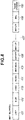
Fig. 6] Fig. 6 illustrates an example of a PHY frame structure of an EHT Extended Range (ER) PPDU according to the present exemplary embodiment. - Exemplary embodiments of the present invention will be described in detail below with reference to the accompanying drawings.
-
Fig. 1 illustrates an example of a network configuration according to the present exemplary embodiment. Awireless network 101 inFig. 1 includes an access point (hereinafter referred to as an AP) 102 and a plurality of stations (hereinafter referred to as STAs) 103, 104, and 105. For example, the AP 102 is an access point conforming to the IEEE 802.11 standard and includes a Group Owner (hereinafter referred to as a GO) conforming to the Wi-Fi Direct standard. When the AP 102 is a GO, the plurality of stations (STAs 103 to 105) is also referred to as Clients. - The AP 102 configures the
wireless network 101 conforming to the IEEE 802.11 standard and transmits a beacon including identification information for the wireless network. The dotted line enclosing thewireless network 101 inFig. 1 indicates the coverage of the signal transmitted by the AP 102. The AP 102 can communicate with theSTAs - When the AP 102 receives a Probe Request message transmitted from an STA, the AP 102 transmits a Probe Response message as a response. The Probe Response message includes identification information for the
wireless network 101. Examples of pieces of the identification information for thewireless network 101 include Service Set Identifier (hereinafter referred to as an SSID). - The AP 102 also communicates with the
STAs 103 to 105 according to a wireless communication method conforming to the IEEE 802.11be standard. The AP 102 establishes a wireless connection with theSTAs 103 to 105 through a predetermined association process. -
Fig. 1 illustrates an example of a network. For example, the following argument about the positional relations between various communication apparatuses is applicable to a network including a number of communication apparatuses in a wide range of regions. -
Fig. 2 illustrates a hardware configuration of each of the AP 102 and theSTAs 103 to 105 as a communication apparatus according to the present exemplary embodiment. The AP 102 according to the present exemplary embodiment may be not only an AP-dedicated apparatus, such as what is called a wireless Local Area Network (LAN) router, but also an apparatus such as a smart phone, camera, printer, or projector. The STAs 103 to 105 may also be an apparatus such as a smart phone, camera, printer, or projector. One communication apparatus may be provided with both an AP function and an STA function. - As an example of a hardware configuration, each of the
AP 102 and theSTAs 103 to 105 includes astorage unit 201, acontrol unit 202, afunction unit 203, aninput unit 204, anoutput unit 205, acommunication unit 206, and anantenna 207. - The
storage unit 201 includes both or either one of at least one read only memory (ROM) and at least one random access memory (RAM) for storing various kinds of information such as programs that perform various operations (described below) and communication parameters for wireless communication. Thestorage unit 201 may include memories (a ROM and a RAM) and storage media such as a flexible disk, hard disk, optical disk, magneto-optical (MO) disk, compact disc read only memory (CD-ROM), compact disc recordable (CD-R), magnetic tape, nonvolatile memory card, and digital versatile disc (DVD). - The
control unit 202 includes, for example, at least one processor such as a Central Processing Unit (CPU) or a Micro Processing Unit (MPU), an Application Specific Integrated circuit (ASIC), a Digital Signal Processor (DSP), and a Field Programmable Gate Array (FPGA). The CPU is an abbreviation for Central Processing Unit, and the MPU is an abbreviation for Micro Processing Unit. Thecontrol unit 202 controls the entire apparatus by executing programs stored in thestorage unit 201. Thecontrol unit 202 may control the entire apparatus through the collaboration of programs and an Operating System (OS) stored in thestorage unit 201. - The
control unit 202 controls thefunction unit 203 to perform image capturing, printing, projection, and other predetermined processing. Thefunction unit 203 is a hardware component that enables the AP 102 or each STA to perform predetermined processing. For example, when theAP 102 or each STA is a camera, thefunction unit 203 is an imaging unit that performs image capture processing. For example, when theAP 102 or each STA is a printer, thefunction unit 203 is a printing unit that performs print processing. For example, when theAP 102 or each STA is a projector, thefunction unit 203 is a projection unit that performs projection processing. Data processed by thefunction unit 203 may be data stored in thestorage unit 201 or data received through communication with other APs or STAs via the communication unit 206 (described below). - The
input unit 204 receives various operations from the user. Theoutput unit 205 outputs various kinds of data to the user. Data output by theoutput unit 205 includes at least one of screen display, audio output from a speaker, and vibration output. Theinput unit 204 and theoutput unit 205 may be implemented as one module, such as a touch panel. - The
communication unit 206 is what is called a wireless LAN chip that controls wireless communication conforming to the IEEE 802.11 standard series and controls Internet Protocol (IP) communication. According to the present exemplary embodiment, thecommunication unit 206 can perform communication processing conforming to at least the IEEE 802.11be standard. Thecommunication unit 206 is a processing apparatus that generates a Physical layer (PHY) Protocol Data Unit (PPDU) conforming to the IEEE 802.11 standard series. Alternatively, thecommunication unit 206 is a processing apparatus that receives and processes a PPDU generated by other apparatuses. Thecommunication unit 206 according to the present exemplary embodiment generates or processes various PPDUs (described below). Thecommunication unit 206 controls theantenna 207 to transmit and receive wireless communication signals for wireless communication. TheAP 102 or each STA communicates contents such as image data, document data, and video data with other communication apparatuses via thecommunication unit 206. Each member of theantenna 207 can receive signals of a sub GHz band (any one of the 2.4, 5, and 6 GHz bands). Theantenna 207 may physically include two or more antennas to perform multiple-input and multiple-output (MIMO) communication. -
Fig. 3 illustrates the frequency band configuration used in wireless communication according to the present exemplary embodiment. In the 2.4 GHz band used for a wireless LAN, the 20 or 40 MHz frequency bandwidth is applicable. Likewise, in the 5 GHz band used for a wireless LAN, the 20, 40, 80, or 160 MHz frequency bandwidth is applicable. - According to the present exemplary embodiment, further, the 5.925 to 7.125 GHz frequency band, what is called the 6 GHz band is applicable. In the 6 GHz band, the 320 MHz bandwidth is also applicable in addition to the 20, 40, 80, and 160 MHz frequency bandwidths.
Fig. 3 illustrates an example of a frequency band configuration. Frequency bands other than the above-described ones may be applicable, and the 320 MHz bandwidth may also be applicable in the 5 GHz band. -
Figs. 4 to 6 illustrate examples of wireless frames, i.e., frame formats of an Extremely High Throughput (EHT) Single User (SU) Physical layer Protocol Data Unit (PPDU), an EHT Multi User (MU) PPDU, and an EHT Extended Range (ER) PPDU, conforming to the IEEE 802.11be standard according to the present exemplary embodiment. The EHT is an abbreviation for Extremely High Throughput. These PPDUs include the preamble portion, the data fields, and the Packet Extension portion of the physical layer (PHY). The preamble of a PPDU includesfields 401 to 407 (501 to 508 or 601 to 607). Various kinds of data in the Media Access Control (MAC) layer and higher-level layers are stored indata fields Figs. 4 to 6 illustrate examples of frame formats. Each PPDU may include fields other than the following fields, and some fields may be omitted. The order of the fields is not limited to the order illustrated inFigs. 4 to 6 . - Information included in each PPDU includes a Short Training Field (STF), a Long Term Field (LTF), and a Signal Field (SIG).
- The head portion of the PPDU includes a Legacy-STF (L-STF) 401, a Legacy-LTF (L-LTF) 402, and a Legacy-Signal (L-SIG) 403 having backward compatibility with the IEEE 802.11a/b/g/n/ac/ax standard.
- The L-
STF 401 is used to perform PHY frame signal detection, automatic gain control (AGC), and timing detection. The L-LTF 602 is used for high-precision frequency/time synchronization, channnel state information (CSI) acquisition, and the like. The L-SIG 403 is used to transmit control information including information about the communication rate and length. - A legacy device conforming to the IEEE 802.11a/b/g/n/ac/ax standard is capable of decoding data of the above-described various legacy fields.
- The EHT SU PPDU in
Fig. 4 is a PPDU used for Single User communication (between theAP 102 and a single STA). The EHT SU PPDU includes the L-STF 401, the L-LTF 02, the L-SIG 403, a Repeated Legacy Signal (RL-SIG) 404, an Extremely High Throughput-Signal-A (EHT-SIG-A) 405, an Extremely High Throughput-Short Training Field (EHT-STF) 406, and an Extremely High Throughput-Long Training Field (EHT-LTF) 407 as preambles. The EHT SU PPDU further includes thedata field 408 and aPacket extention 609. - An EHT ER SU PPDU in
Fig. 6 uses a PPDU used for an Extended Range (when extending the communication range) in communication between theAP 102 and a single STA. The EHT ER PPDU includes the L-STF 601, the L-LTF 602, the L-SIG 603, the RL-SIG 604, the EHT-SIG-A 605, the EHT-STF 606, and the EHT-LTF 607 as preambles. The EHT ER SU PPDU further includes thedata field 608 and thePacket extention 609. To extend the communication range, the EHT ER SU PPDU is different from the EHT SU PPDU in that the applicable MCS (modulation method and coding rate) is limited. - As illustrated in Tables 1 and 2, the EHT-SIG-As 405 and 605 included in the EHT SU PPDU and the EHT ER SU PPDU include information about the EHT-SIG-A1 and the EHT-SIG-A2 necessary for the reception of the PPDU.
- According to the present exemplary embodiment, information about the frequency bandwidth to be used and Preamble Puncturing is indicated by the Bandwidth field of the EHT-SIG-A1. For example, the value 0 of the Bandwidth field indicates the use of the 20 MHz bandwidth, the value 1 indicates the use of the 40 MHz bandwidth, the value 2 indicates the use of the 80 MHz bandwidth, the value 3 indicates the use of the 160 MHz bandwidth, and the value 4 indicates the use of the 320 MHz bandwidth. These values indicate that the Preamble Puncturing mode is not to be used. The
value 5 of the Bandwidth field indicates that only secondary 20 MHz is subjected to puncturing in 80 MHz Preamble Puncturing. A frequency band subjected to puncturing means that the frequency band is not to be used. Thevalue 6 of the Bandwidth field indicates that either one of two 20 MHz of secondary 40 MHz is subjected to puncturing in 80 MHz Preamble Puncturing. The value 7 of the Bandwidth field indicates that only secondary 20 MHz is subjected to puncturing in 160 (or 80 + 80) MHz Preamble Puncturing. The value 8 of the Bandwidth field indicates that at least one 20 MHz other than primary 40 MHz is subjected to puncturing in 160 (or 80 + 80) MHz Preamble Puncturing. The value 9 of the Bandwidth field indicates that only secondary 20 MHz is subjected to puncturing in 320 MHz Preamble Puncturing. The value 10 of the Bandwidth field indicates that either one of two 20 MHz of secondary 40 MHz is subjected to puncturing in 320 MHz Preamble Puncturing. The value 11 of the Bandwidth field indicates that at least one 20 MHz other than primary 80 MHz is subjected to puncturing in 320 MHz Preamble Puncturing. To indicate these pieces of information, at least 4 bits are assigned to the Bandwidth field of the EHT-SIG-A1. The above-described correspondence relation between the value of the Bandwidth field and the assignment of the frequency band subjected to puncturing is to be considered as an example. Assignments other than the above-described ones are applicable as long as they are related to the 320 MHz bandwidth. Names, bit positions, and sizes for each field are not limited to the values illustrated in Tables 1 and 2. Similar information may be stored with different field names, orders, and sizes. -
Table 1 Bit Position Sub Field No. of Bits Description EHT-SIG-A1 B0 Format 1 1 when "EHT PPDU and EHT ER PPDU" is specified to distinguish from EHT TB PPDU. B1 Beam Change 1 1 when pre-EHT of PPDU is disposed in a space different from first symbol of EHT-LTF, or 0 when it is similarly mapped. B2 UL/DL 1 Indicates whether PPDU is for UL or for DL, and is set to the same value as TXVECTOR UPLINK_FLAG. B3-B6 MCS 4 Value of Modulation and Coding Scheme For EHT SU PPDU: n = 0, 1, 2, ...11 (12 to 15 are reserved) For EHT ER SU PPDU and Bandwidth = 0: n = 0, 1, 2 (3 to 15 are reserved) For EHT ER SU PPDU and Bandwidth = 1: For MCS 0, n = 0 (1 to 15 are reserved) B7-B12 BSS Color 6 A 6-bit number that identifies BSS B13-B16 Spatial Reuse 4 Indicates whether Spatial Reuse is permitted during transmission of this PPDU. Value of Spatial Reuse field encoding illustrated in different table is set. B17-B20 Bandwidt h 4 0 for 20 MHz 1 for 40 MHz 2 for 80 MHz 3 for 160 MHz (80 + 80 MHz) 4 for 320 MHz 5 when only secondary 20 MHz is subjected to puncturing in 80 MHz Preamble Puncturing. 6 when either one of two 20 MHz of secondary 40 MHz is subjected to puncturing in 80 MHz Preamble Puncturing. 7 when only secondary 20 MHz is subjected to puncturing in 160 (or 80 + 80) MHz Preamble Puncturing. 8 when at least one 20 MHz other than primary 40 MHz is subjected to puncturing in 160 (or 80 + 80) MHz Preamble Puncturing. 9 when only secondary 20 MHz is subjected to puncturing in 320 MHz Preamble Puncturing. 10 when either one of two 20 MHz of secondary 40 MHz is subjected to puncturing in 320 MHz Preamble Puncturing. 11 when at least one 20 MHz other than primary 80 MHz is subjected to puncturing in 320 MHz Preamble Puncturing. 12 to 15 are reserved. -
[Table 2] Table 1 (Continued) Bit Position Sub Field No. of Bits Description EHT-SIG-A1 B21-B22 GI+LTF Size 2 Indicates Guard Interval and size of EHT-LTF. 0 for 1xEHT-LTF and 0.8 µs GI 1 for 2xEHT-LTF and 0.8 µs GI 2 for 2xEHT-LTF and 1.6 µs GI 3 for both DCM and STBC fields of 1, and 4xEHT-LTF, and 0.8 µs GI 3 for 4xEHT-LTF and 3.2 µs GI in other cases B23-B25 NSTS And Midamble Periodicit y 3 Number of space-time streams and midamble interval for frame synchronization When Doppler field is 0: Number of space-time streams - 1 When Doppler field is 1: B23 to B24 indicate the number of space-time streams. B25 is 0 when midamble interval is 10, or 1 when it is 20. -
Table 2 Bit Position Sub Field No. of Bits Description EHT-SIG-A2 BO-B6 TXOP 7 Transmission Opportunity 127 when TXOP_DURATION of TXVECTOR is UNSPECIFIED and no interval information exists. When TXOP_DURATION of TXVECTOR is smaller than 512, a value smaller than 127 is set to set NAV. In this case, when B0 is 0, B1 to B6 indicate FLOOR of TXOP_DURATION/8 (rounded off). When B0 is 1, B1 to B6 indicate FLOOR of (TXOP_DURATION-512)/8. B7 Coding 1 0 for Binary Convolutional Code (BCC), or 1 for Low Density Parity Check (LDPC) B8 LDPC Extra Symbol Segment 1 Indicates presence or absence of extra OFDM symbol segment for LDPC. B9 STBC 1 This field is 1 when Space-Time Block Coding (STBC) is used and DCM is 0. 1 when neither DCM nor STBC is applied. 0 for other cases. B10 Beamfor med 1 1 when beamforming steering is applied to waveform of SU transmission. B11-B12 Pre-FEC Padding Factor 2 0, 1, 2, or 3 when Pre-FEC Padding Factor is 4, 1, 2, or 3, respectively. B13 PE Disambiguity 1 Disambiguity field of Packet Extention B14 DCM 1 Indicates whether Dual Carrier Modulation is applied to data field. 1 when STBC field is 0. (When both DCM and STBC fields are 1, neither DCM nor STBC is applied.) 0 when DCM is not applied. B15 Doppler 1 1 when either one of the following conditions is satisfied: ∗ The number of OFDM symbols of data field is larger than "Value indicated by midamble interval + I", and midamble exists. ∗ When the number of OFDM symbols of data field is equal to or less than "Value indicated by midamble interval + 1", and no midamble exists, and channel change is fast. -
[Table 4] Table 2 (Continued) Bit Position Sub Field No. of Bits Description EHT-SIG-A2 B16-B19 CRC 4 CRC of EHT-SIG-A field so far (26 bits of A1 and 16 bits of up to B15 of A2, 41 bits in total) B20- B25 Tail 6 0 is set to indicate the end to trellis convolution decoder. - The EHT MU PPDU in
Fig. 5 is a PPDU used for Multi User communication (between the AP and a plurality of STAs). The EHT MU PPDU includes the L-STF 501, the L-LTF 502, the L-SIG 503, the RL-SIG 504, the EHT-SIG-A 505, the EHT-SIG-B 506, the EHT-STF 507, and the EHT-LTF 507 as preambles. The EHT MU PPDU further includes thedata field 508 and thePacket extention 509. - The EHT-SIG-
A 505 includes information about the EHT-SIG-A1 and EHT-SIG-A2 necessary for the reception of the PPDU, as illustrated in Tables 3 and 4. - According to the present exemplary embodiment, information about the frequency bandwidth to be used and Preamble Puncturing is indicated by the Bandwidth field of the EHT-SIG-A1. For example, the value 0 of the Bandwidth field indicates the use of the 20 MHz bandwidth, the value 1 indicates the use of the 40 MHz bandwidth, the value 2 indicates the use of the 80 MHz bandwidth, the value 3 indicates the use of the 160 MHz bandwidth, and the value 4 indicates the use of the 320 MHz bandwidth. These values indicate that the Preamble Puncturing mode is not to be used. The
value 5 of the Bandwidth field indicates that only secondary 20 MHz is subjected to puncturing in 80 MHz Preamble Puncturing. A frequency band subjected to puncturing means that the frequency band is not to be used. Thevalue 6 of the Bandwidth field indicates that either one of two 20 MHz of secondary 40 MHz is subjected to puncturing in 80 MHz Preamble Puncturing. The value 7 of the Bandwidth field indicates that only secondary 20 MHz is subjected to puncturing in 160 (or 80 + 80) MHz Preamble Puncturing. The value 8 of the Bandwidth field indicates that at least one 20 MHz other than primary 40 MHz is subjected to puncturing in 160 (or 80 + 80) MHz Preamble Puncturing. The value 9 of the Bandwidth field indicates that only secondary 20 MHz is subjected to puncturing in 320 MHz Preamble Puncturing. The value 10 of the Bandwidth field indicates that either one of two 20 MHz of secondary 40 MHz is subjected to puncturing in 320 MHz Preamble Puncturing. The value 11 of the Bandwidth field indicates that at least one 20 MHz other than primary 80 MHz is subjected to puncturing in 320 MHz Preamble Puncturing. To indicate these pieces of information, at least 4 bits are assigned to the Bandwidth field of the EHT-SIG-A1. The above-described correspondence relation between the value of the Bandwidth field and the assignment of the frequency band subjected to puncturing is to be considered as an example. Assignments other than the above-described ones are applicable as long as they are related to the 320 MHz bandwidth. Names, bit positions, and sizes for each field are not limited to the values illustrated in Tables 1 and 2. Similar information may be stored with different field names, orders, and sizes. - As described above, the EHT SU PPDU, the EHT ER SU PPDU, and the EHT MU PPDU conforming to the IEEE 802.11be standard enable implementing Preamble Puncturing by specifying a frequency band exceeding 160 MHz. In the above descriptions, the information about the Bandwidth field is the same for the EHT SU PPDU, the EHT ER SU PPDU, and the EHT MU PPDU. However, the correspondence relation between the value of the Bandwidth field and the assignment of the frequency band subjected to puncturing may be different between the SU PPDU and the MU PPDU. When the MU PPDU (multi user communication) performs Preamble Puncturing, for example, communication bands can be assigned to different users (STAs) for each frequency width in 20 MHz units. For example, in the case of the MU PPDU (multi user communication), the number of frequency bands subjected to puncturing may be larger than that for the SU PPDU (single user communication) and the corresponding value of the Bandwidth field may be defined. This enables improving the degrees of freedom of using the frequency band in multi user communication in comparison with single user communication.
-
Table 3 Bit Position Sub Field No. of Bits Description EHT-SIG-A1 B0 UL/DL 1 Indicates whether PPDU is for UL or for DL, and is set to the same value as TXVECTOR UPLINK_FLAG. B1-B3 SIGBMC S 3 Indicates MCS of EHT-SIG-B field. 0, 1, 2, 3, 4, or 5 when MCS is 0, 1, 2, 3, 4, or 5, respectively. 6 and 7 are reserved. B4 SIGBDC M 1 1 when EHT-SIG-B field is modulated by DCM. B5-B10 BSS Color 6 A 6-bit number that identifies BSS B11-B14 Spatial Reuse 4 Indicates whether Spatial Reuse is permitted during transmission of this PPDU. Value of Spatial Reuse field encoding illustrated in different table is set. B15-B18 Bandwidt h 3 0 for 20 MHz 1 for 40 MHz 2 for 80 MHz 3 for 160 MHz (80 + 80 MHz) 4 for 320 MHz 5 when only secondary 20 MHz is subjected to puncturing in 80 MHz Preamble Puncturing. 6 when either one of two 20 MHz of secondary 40 MHz is subjected to puncturing in 80 MHz Preamble Puncturing. 7 when only secondary 20 MHz is subjected to puncturing in 160 (or 80 + 80) MHz Preamble Puncturing. 8 when at least one 20 MHz other than primary 40 MHz is subjected to puncturing in 160 (or 80 + 80) MHz Preamble Puncturing. 9 when only secondary 20 MHz is subjected to puncturing in 320 MHz Preamble Puncturing. 10 when either one of two 20 MHz of secondary 40 MHz is subjected to puncturing in 320 MHz Preamble Puncturing. 11 when at least one 20 MHz other than primary 80 MHz is subjected to puncturing in 320 MHz Preamble Puncturing. 12 to 15 are reserved. -
[Table 6] Table 3 (Continued) Bit Position Sub Field No. of Bits Description EHT-SIG-A1 B19-B22 Number Of EHT-SIG-B Symbols or MU-MIMO Users 4 Indicates the number of OFDMA symbols of EHT-SIG-B when SIGB Compression field is 0. The number of OFDM symbols of EHT-SIG-B minus 1 when the number of OFDM symbols of EHT-SIG-B is smaller than 16. When at least one receiving station sets capacity for supporting the number of OFDM symbols of EHT SIG-B larger than 16 to 0, 15 is set to indicate that the number of OFDM symbols of EHT-SIG-B is 16. 15 is set to indicate that the number of OFDM symbols of EHT-SIG-B is equal to or larger than 16 when all of receiving stations set capacity for supporting the number of OFDM symbols of EHT SIG-B larger than 16 to 0, and data rate of EHT-SIG-B is smaller than that of MCS 4 that does not use DCM. Means the number of MU-MIMO users minus 1 when SIGB Compression field is 1. B23-B24 GI+LTF Size 2 Indicates Guard Interval and size of EHT-LTF. 0 for 4xEHT-LTF and 0.8 µs GI 1 for 2xEHT-LTF and 0.8 µs GI 2 for 2xEHT-LTF and 1.6 µs GI 3 for 4xEHT-LTF and 3.2 µs GI B25 Doppler 1 1 when either one of the following conditions is satisfied: ∗ The number of OFDM symbols of data field is larger than "Value indicated by midamble interval + I", and midamble exists. ∗ When the number of OFDM symbols of data field is equal to or less than "Value indicated by midamble interval + 1", and no midamble exists, and channel change is fast. -
Table 4 Bit Position Sub Field No. of Bits Description EHT-SIG-A2 BO-B6 TXOP 7 Transmission Opportunity 127 when TXOP_DURATION of TXVECTOR is UNSPECIFIED and no interval information exists. When TXOP_DURATION of TXVECTOR is smaller than 512, a value smaller than 127 is set to set NAV. In this case, when B0 is 0, B1 to B6 indicate FLOOR of TXOP_DURATION/8 (rounded off). When B0 is 1, B1 to B6 indicate FLOOR of (TXOP_DURATION-512)/8. B7 SIG Compress ion 1 1 when Common field exists in EHT-SIG-B. B8-B10 Number of EHT-LTF Symbols And Midamble Periodicit y Indicates the number of EHT-LTFs. 0 for 1EHT-LTF 1 for 2EHT-LTF 3 2 for 4EHT-LTF 3 for 6EHT-LTF 4 for 8EHT-LTF When Doppler field is 1, B8 to B9 indicate the number of EHT-LTF symbols and B10 indicates midamble interval. B11 LDPC Extra Symbol Segment 1 Indicates presence or absence of extra OFDM symbol segment for LDPC. B12 STBC 1 When the number of users for each Resource Unit (RU) is not larger than 1, 1 is set to indicate encoding by STBC. B13-B14 Pre-FEC Padding Factor 2 0, 1, 2, or 3 when Pre-FEC Padding Factor is 4, 1, 2, or 3, respectively B15 PE Disambig uity 1 Disambiguity field of Packet Extention B16-B19 CRC 4 CRC of EHT-SIG-A field so far (26 bits of A1 and 16 bits of up to B15 of A2, 41 bits in total) B20- B25 Tail 6 0 is set to indicate the end to trellis convolution decoder. - In the above-described examples, information about Preamble Puncturing is indicated by the Bandwidth field of the EHT-SIG-A1. Then, 4 bits are assigned to the Bandwidth Field of the EHT-SIG-A1 to indicate information when the 320 MHz frequency bandwidth is to be used. In the following example, the Bandwidth field of the EHT-SIG-A1 is assigned 3 bits, the EHT-SIG-A3 field is separately added, and these fields indicate information about Preamble Puncturing.
- The value 0 of the Bandwidth field of the EHT-SIG-A1 indicates that the 20 MHz frequency bandwidth is to be used. The value 1 of the Bandwidth field of the EHT-SIG-A1 indicates that the 40 MHz frequency bandwidth is to be used. The value 2 of the Bandwidth field of the EHT-SIG-A1 indicates that the 80 MHz frequency bandwidth is to be used. The value 3 of the Bandwidth field of the EHT-SIG-A1 indicates that the 160 MHz frequency bandwidth is to be used. The value 4 of the Bandwidth field of the EHT-SIG-A1 indicates that the 320 MHz frequency bandwidth is to be used. The values 0 to 4 of the Bandwidth field of the EHT-SIG-A1 indicate that Preamble Puncturing is not to be performed. The
value 5 of the Bandwidth field of the EHT-SIG-A1 indicates that the 80 MHz frequency bandwidth is to be used and that Preamble Puncturing is to be performed. Thevalue 6 of the Bandwidth field of the EHT-SIG-A1 indicates that the 160 MHz frequency bandwidth is to be used and that Preamble Puncturing is to be performed. The value 7 of the Bandwidth field of the EHT-SIG-A1 indicates that the 320 MHz frequency bandwidth is to be used and that Preamble Puncturing is to be performed. Further, in the case of thevalues 5 to 7 of the Bandwidth field of the EHT-SIG-A1, the EHT-SIG-A3 illustrated in Table 5 is to be included in the EHT-PPDU. Names, bit positions, and sizes for each field inFig. 5 are to be considered as examples. As long as similar information is indicated, different names, positions, and sizes may be used. - The EHT-SIG-A3 illustrated in Table 5 includes the Preamble Puncturing field that indicates the frequency bandwidth subjected to Preamble Puncturing. The Preamble Puncturing field in Table 5 has a 16-bit length and is sequentially associated with the 20 MHz bandwidth from the bit position B0. When using the 20 MHz band, the corresponding bit is set to 0. Otherwise, i.e., Puncturing is to be performed, the corresponding bit is set to 1.
The definitions of 0 and 1 for each bit may be reversed. More specifically, in Table 5, the frequency band to be used is represented in the bitmap format. - For example, when the 80 MHz Frequency bandwidth is to be used, and only secondary 20 MHz is subjected to Puncturing, the value of the Bandwidth field of the EHT-SIG-A1 is 5. For the Preamble Puncturing field of the EHT-SIG-A3, only the B1 bit is set to 1 and other bits are set to 0. The bitmap may have a variable length according to the frequency bandwidth specified by the Bandwidth field of the EHT-SIG-A1. More specifically, the length of the bitmap may be 4 bits for the 80 MHz frequency bandwidth, 8 bits for the 160 MHz frequency bandwidth, and 16 bits for the 320 MHz frequency bandwidth. In this case, excessive high-order bits for the frequency bandwidth specified by the Bandwidth field of the EHT-SIG-A1 may be unused or reserved.
-
Table 5 Bit Position Sub Field No. of Bits Description EHT-SIG-A3 B0B15 Preamble Puncturin g 16 Specifies frequency band subjected to Puncturing. Corresponds to whether frequency bandwidth sequentially delimited in 20 MHz steps from value of the lowest frequency of 320 MHz bandwidth from B0 is subjected to Puncturing. Frequency bandwidth is not subjected to Puncturing when the bit is 0 or is subjected to Puncturing when it is 1. B16-B19 CRC 4 CRC of HE-SIG-A field so far B20- B25 Tail 6 0 is set to indicate the end to trellis convolution decoder. - As yet another modification, the frequency band subjected to Preamble Puncturing may be indicated as follows instead of the example in Table 5. More specifically, the value 0 of the Preamble Puncturing field of the EHT-SIG-A3 indicates that all of the frequency bandwidths are to be used, i.e., Preamble Puncturing is not to be performed. The value 1 of the Preamble Puncturing field of the EHT-SIG-A3 indicates that the lowest frequency bandwidth 20 MHz is subjected to puncturing. The value 2 of the Preamble Puncturing field of the EHT-SIG-A3 indicates that 20 MHz from the lowest 20Hz to 40 MHz frequency bandwidth is subjected to puncturing. The value 3 of the Preamble Puncturing field of the EHT-SIG-A3 indicates that 20 MHz from the lowest 40Hz to 60 MHz frequency bandwidth is subjected to puncturing. The value of the Preamble Puncturing field of the EHT-SIG-A3 may be defined as above. However, the above-described examples may be other methods.
- As discussed above, according to the present exemplary embodiment and each modification, Preamble Puncturing can be suitably performed even if the 320 MHz frequency bandwidth is to be used for wireless LAN communication. The
AP 102 or each STA can generate the EHT-SIG-A field in the PPDU frame of the wireless LAN to perform appropriate Preamble Puncturing. By communicating these PPDU frames between theAP 102 and each STA, Preamble Puncturing can be suitably performed in wireless LAN communication between theAP 102 and each STA. - The present invention can also be achieved when a program for implementing at least one of the functions according to the above-described exemplary embodiments is supplied to a system or apparatus via a network or storage medium, and at least one processor in the computer of the system or apparatus reads and executes the program. Further, the present invention can also be achieved by a circuit (for example, an application specific integrated circuit (ASIC)) that implements at least one function.
- The present invention is not limited to the above embodiments and various changes and modifications can be made within the spirit and scope of the present invention. Therefore, to apprise the public of the scope of the present invention, the following claims are made.
- This application claims priority from
Japanese Patent Application No. 2019-203513 filed November 8, 2019
Claims (9)
- A communication apparatus capable of performing wireless communication conforming to an IEEE 802.11 standard, comprising a transmission unit configured to transmit a wireless frame having preambles and data fields of a physical layer (PHY),wherein the preambles include a Legacy Short Training Field (L-STF), a Legacy Long Training Field (L-LTF), a Legacy Signal Field (L-SIG), an Extremely High Throughput Signal A Field (EHT-SIG-A), an EHT Short Training Field (EHT-STF), and an EHT Long Training Field (EHT-LTF), andwherein the EHT-SIG-A includes information about Preamble Puncturing in a case where a 320 MHz frequency bandwidth is to be used by the communication apparatus.
- The communication apparatus according to claim 1, wherein the EHT-SIG-A indicates information about a frequency bandwidth to be used by the communication apparatus and information about a frequency band subjected to Preamble Puncturing in a case where the frequency bandwidth is used, as values of one sub field.
- The communication apparatus according to claim 1, wherein the EHT-SIG-A indicates information about the frequency bandwidth to be used by the communication apparatus and information about a frequency band subjected to Preamble Puncturing in a case where the frequency bandwidth is used, as values of a different sub field.
- The communication apparatus according to any one of claims 1 to 3, wherein the wireless frame includes an EHT Single User (SU) Physical layer Protocol Data Unit (PPDU) and an EHT Multi User (MU) PPDU.
- A communication apparatus capable of performing wireless communication conforming to an IEEE 802.11 standard, comprising a reception unit configured to receive a wireless frame having preambles and data fields of a physical layer (PHY),wherein the preambles include a Legacy Short Training Field (L-STF), a Legacy Long Training Field (L-LTF), a Legacy Signal Field (L-SIG), an Extremely High Throughput Signal A Field (EHT-SIG-A), an EHT Short Training Field (EHT-STF), and an EHT Long Training Field (EHT-LTF), andwherein the EHT-SIG-A includes information about Preamble Puncturing in a case where a 320 MHz frequency bandwidth is to be used by the communication apparatus.
- A processing apparatus comprising a generation unit configured to generate a wireless frame having preambles and data fields of a physical layer (PHY),wherein the preambles include a Legacy Short Training Field (L-STF), a Legacy Long Training Field (L-LTF), a Legacy Signal Field (L-SIG), an Extremely High Throughput Signal A Field (EHT-SIG-A), an EHT Short Training Field (EHT-STF), and an EHT Long Training Field (EHT-LTF), andwherein the EHT-SIG-A includes information about Preamble Puncturing in a case where a 320 MHz frequency bandwidth is to be used in wireless communication conforming to an IEEE 802.11 standard.
- A communication method for performing wireless communication conforming to an IEEE 802.11 standard, the method comprising transmitting a wireless frame having preambles and data fields of a physical layer (PHY),wherein the preambles include a Legacy Short Training Field (L-STF), a Legacy Long Training Field (L-LTF), a Legacy Signal Field (L-SIG), an Extremely High Throughput Signal A Field (EHT-SIG-A), an EHT Short Training Field (EHT-STF), and an EHT Long Training Field (EHT-LTF), andwherein the EHT-SIG-A includes information about Preamble Puncturing in a case where a 320 MHz frequency bandwidth is to be used in wireless communication conforming to the IEEE 802.11 standard.
- A communication method for performing wireless communication conforming to an IEEE 802.11 standard, the method comprising receiving a wireless frame having preambles and data fields of a physical layer (PHY),wherein the preambles include a Legacy Short Training Field (L-STF), a Legacy Long Training Field (L-LTF), a Legacy Signal Field (L-SIG), an Extremely High Throughput Signal A Field (EHT-SIG-A), an EHT Short Training Field (EHT-STF), and an EHT Long Training Field (EHT-LTF), andwherein the EHT-SIG-A includes information about Preamble Puncturing in a case where a 320 MHz frequency bandwidth is to be used in wireless communication conforming to the IEEE 802.11 standard.
- A program for causing a computer to operate as the communication apparatus according to any one of claims 1 to 5.
Applications Claiming Priority (2)
| Application Number | Priority Date | Filing Date | Title |
|---|---|---|---|
| JP2019203513A JP7379100B2 (en) | 2019-11-08 | 2019-11-08 | Communication devices, communication methods, and programs |
| PCT/JP2020/040266 WO2021090733A1 (en) | 2019-11-08 | 2020-10-27 | Communication device, communication method, and program |
Publications (2)
| Publication Number | Publication Date |
|---|---|
| EP4057744A1 true EP4057744A1 (en) | 2022-09-14 |
| EP4057744A4 EP4057744A4 (en) | 2023-12-13 |
Family
ID=75848385
Family Applications (1)
| Application Number | Title | Priority Date | Filing Date |
|---|---|---|---|
| EP20886115.3A Pending EP4057744A4 (en) | 2019-11-08 | 2020-10-27 | Communication device, communication method, and program |
Country Status (6)
| Country | Link |
|---|---|
| US (3) | US11843973B2 (en) |
| EP (1) | EP4057744A4 (en) |
| JP (3) | JP7379100B2 (en) |
| KR (2) | KR20250152663A (en) |
| CN (2) | CN114642061B (en) |
| WO (1) | WO2021090733A1 (en) |
Families Citing this family (8)
| Publication number | Priority date | Publication date | Assignee | Title |
|---|---|---|---|---|
| JP7527772B2 (en) * | 2019-11-07 | 2024-08-05 | キヤノン株式会社 | COMMUNICATION DEVICE, CONTROL METHOD, AND PROGRAM |
| JP7379100B2 (en) * | 2019-11-08 | 2023-11-14 | キヤノン株式会社 | Communication devices, communication methods, and programs |
| CN113395143B (en) * | 2020-03-12 | 2023-06-27 | 华为技术有限公司 | Data transmission method and device, chip system and computer readable storage medium |
| KR20230083869A (en) | 2021-12-03 | 2023-06-12 | 삼성전자주식회사 | Apparatus and method for wireless communication based on puncturing |
| JP7797255B2 (en) * | 2022-03-11 | 2026-01-13 | キヤノン株式会社 | COMMUNICATION DEVICE, COMMUNICATION DEVICE CONTROL METHOD, AND PROGRAM |
| US20230023324A1 (en) * | 2022-09-30 | 2023-01-26 | Juan Fang | Apparatus, system, and method of communicating an extended range (er) physical layer (phy) protocol data unit (ppdu) |
| EP4351067A1 (en) | 2022-10-04 | 2024-04-10 | Samsung Electronics Co., Ltd. | Device and method for supporting communication using plurality of bandwidths in wireless local area network system |
| KR102923023B1 (en) | 2025-05-21 | 2026-02-03 | 이지운 | Liver stem easy to assemble bouy for seaweed farming |
Family Cites Families (24)
| Publication number | Priority date | Publication date | Assignee | Title |
|---|---|---|---|---|
| US8982889B2 (en) * | 2008-07-18 | 2015-03-17 | Marvell World Trade Ltd. | Preamble designs for sub-1GHz frequency bands |
| US9025428B2 (en) * | 2010-04-14 | 2015-05-05 | Qualcomm Incorporated | Allocating and receiving tones for a frame |
| US8750215B2 (en) * | 2012-03-06 | 2014-06-10 | Intel Corporation | Method and apparatus for a 1 MHz long training field design |
| US20130337027A1 (en) | 2012-05-24 | 2013-12-19 | Massachusetts Institute Of Technology | Medical Devices and Implements with Liquid-Impregnated Surfaces |
| CN105519065B (en) * | 2014-02-13 | 2019-05-24 | 华为技术有限公司 | Method and apparatus for transmitting data |
| AU2015304131B2 (en) * | 2014-08-21 | 2018-08-02 | Lg Electronics Inc. | Method for uplink transmission in wireless communication system and apparatus therefor |
| KR20160056287A (en) * | 2014-11-11 | 2016-05-19 | 뉴라컴 인코포레이티드 | Method for transmitting frame, method for receiving frame, and apparatus implementing the same method |
| JP6459015B2 (en) * | 2015-01-08 | 2019-01-30 | マーベル ワールド トレード リミテッド | Method and apparatus |
| KR20160092929A (en) * | 2015-01-28 | 2016-08-05 | 뉴라컴 인코포레이티드 | Transmission control method |
| US10178705B2 (en) * | 2015-02-23 | 2019-01-08 | Newracom, Inc. | Method and apparatus for dynamic channel sensing for direct link in a high efficiency wireless LAN |
| CN108476550A (en) * | 2015-11-09 | 2018-08-31 | 纽瑞科姆有限公司 | Communication of user-specific control information in wireless networks |
| JP7005499B2 (en) * | 2015-12-21 | 2022-01-21 | クゥアルコム・インコーポレイテッド | Preamble design aspects for high efficiency wireless local area networks |
| US10129064B1 (en) * | 2016-08-02 | 2018-11-13 | Newracom, Inc. | Wireless device low power wake up |
| JP2018050133A (en) | 2016-09-20 | 2018-03-29 | キヤノン株式会社 | Communication device, control method, and program |
| KR102082093B1 (en) * | 2017-01-09 | 2020-02-27 | 주식회사 윌러스표준기술연구소 | Wireless communication method and wireless communication terminal for signaling of multi-user packet |
| US20190141717A1 (en) * | 2017-11-06 | 2019-05-09 | Qualcomm Incorporated | Techniques for interleaving in single user preamble puncturing |
| US10827385B2 (en) * | 2017-11-06 | 2020-11-03 | Qualcomm Incorporated | Techniques for preamble puncturing |
| US10772099B2 (en) * | 2018-02-16 | 2020-09-08 | Qualcomm Incorporated | Punctured sounding and partial bandwidth feedback |
| JP6467733B1 (en) | 2018-05-21 | 2019-02-13 | Smc株式会社 | Method and apparatus for driving fluid pressure cylinder |
| US10374749B1 (en) * | 2018-08-22 | 2019-08-06 | Cisco Technology, Inc. | Proactive interference avoidance for access points |
| WO2020040622A1 (en) * | 2018-08-24 | 2020-02-27 | 엘지전자 주식회사 | Method and apparatus for transmitting ppdu in broadband having preamble puncturing performed in wireless lan system |
| US11564250B2 (en) * | 2019-08-09 | 2023-01-24 | Qualcomm Incorporated | Physical layer preamble and signaling for wireless communication |
| US11665574B2 (en) * | 2019-10-25 | 2023-05-30 | Qualcomm Incorporated | Physical layer preamble design for special packet types |
| JP7379100B2 (en) * | 2019-11-08 | 2023-11-14 | キヤノン株式会社 | Communication devices, communication methods, and programs |
-
2019
- 2019-11-08 JP JP2019203513A patent/JP7379100B2/en active Active
-
2020
- 2020-10-27 KR KR1020257032807A patent/KR20250152663A/en active Pending
- 2020-10-27 CN CN202080077239.2A patent/CN114642061B/en active Active
- 2020-10-27 EP EP20886115.3A patent/EP4057744A4/en active Pending
- 2020-10-27 WO PCT/JP2020/040266 patent/WO2021090733A1/en not_active Ceased
- 2020-10-27 CN CN202511170761.6A patent/CN120750493A/en active Pending
- 2020-10-27 KR KR1020227016680A patent/KR102868398B1/en active Active
-
2022
- 2022-05-03 US US17/735,622 patent/US11843973B2/en active Active
-
2023
- 2023-11-02 JP JP2023188928A patent/JP7657888B2/en active Active
- 2023-11-16 US US18/511,320 patent/US12238577B2/en active Active
-
2024
- 2024-12-17 US US18/984,789 patent/US20250119791A1/en active Pending
-
2025
- 2025-03-26 JP JP2025051946A patent/JP2025102855A/en active Pending
Also Published As
| Publication number | Publication date |
|---|---|
| US20250119791A1 (en) | 2025-04-10 |
| US12238577B2 (en) | 2025-02-25 |
| US20220264367A1 (en) | 2022-08-18 |
| US11843973B2 (en) | 2023-12-12 |
| KR20250152663A (en) | 2025-10-23 |
| EP4057744A4 (en) | 2023-12-13 |
| CN114642061A (en) | 2022-06-17 |
| JP2021078010A (en) | 2021-05-20 |
| JP2025102855A (en) | 2025-07-08 |
| CN120750493A (en) | 2025-10-03 |
| US20240163720A1 (en) | 2024-05-16 |
| JP7379100B2 (en) | 2023-11-14 |
| JP2024003113A (en) | 2024-01-11 |
| KR20220088447A (en) | 2022-06-27 |
| JP7657888B2 (en) | 2025-04-07 |
| WO2021090733A1 (en) | 2021-05-14 |
| KR102868398B1 (en) | 2025-10-13 |
| CN114642061B (en) | 2025-09-09 |
Similar Documents
| Publication | Publication Date | Title |
|---|---|---|
| US12238577B2 (en) | Communication apparatus, processing apparatus, communication method, and storage medium, for throughput improvement of wireless networks | |
| US11032811B2 (en) | Data transmission method in wireless communication system and device therefor | |
| US20230354417A1 (en) | Method and apparatus for transmitting data in wireless communication system | |
| US10999113B2 (en) | Method and device for transmitting data unit | |
| US10548146B2 (en) | Channel sounding method in wireless communication system and device for same | |
| US10404653B1 (en) | Changing a basic service set color identifier | |
| JP7819265B2 (en) | PPDU transmission method and related device | |
| US12341633B2 (en) | Communication device, communication method thereof, information processing device, control method thereof, and computer-readable storage medium | |
| US10708892B1 (en) | Resource request for uplink transmission | |
| EP4607872A2 (en) | Communication device, information processing device, communication method, and program | |
| US20250267511A1 (en) | Communication device, communication method thereof, information processing device, control method thereof, and computer-readable storage medium | |
| US12212972B2 (en) | Access point device, control method, and computer-readable storage medium for BSS color setting | |
| EP3934318A1 (en) | Communication device, communication method and program | |
| US20240235722A1 (en) | Method for Sending Physical Layer Protocol Data Unit and Communication Apparatus | |
| EP3934317A1 (en) | Communication device, communication method and program | |
| US20250071007A1 (en) | Communication apparatus, information processing apparatus, control method, and storage medium | |
| US10212731B2 (en) | TXOP protection method and apparatus | |
| WO2016088956A1 (en) | Method and device for transmitting data unit |
Legal Events
| Date | Code | Title | Description |
|---|---|---|---|
| STAA | Information on the status of an ep patent application or granted ep patent |
Free format text: STATUS: THE INTERNATIONAL PUBLICATION HAS BEEN MADE |
|
| PUAI | Public reference made under article 153(3) epc to a published international application that has entered the european phase |
Free format text: ORIGINAL CODE: 0009012 |
|
| STAA | Information on the status of an ep patent application or granted ep patent |
Free format text: STATUS: REQUEST FOR EXAMINATION WAS MADE |
|
| 17P | Request for examination filed |
Effective date: 20220608 |
|
| AK | Designated contracting states |
Kind code of ref document: A1 Designated state(s): AL AT BE BG CH CY CZ DE DK EE ES FI FR GB GR HR HU IE IS IT LI LT LU LV MC MK MT NL NO PL PT RO RS SE SI SK SM TR |
|
| DAV | Request for validation of the european patent (deleted) | ||
| DAX | Request for extension of the european patent (deleted) | ||
| A4 | Supplementary search report drawn up and despatched |
Effective date: 20231114 |
|
| RIC1 | Information provided on ipc code assigned before grant |
Ipc: H04L 27/26 20060101ALI20231108BHEP Ipc: H04W 84/12 20090101ALI20231108BHEP Ipc: H04W 28/06 20090101ALI20231108BHEP Ipc: H04W 72/04 20090101AFI20231108BHEP |
|
| STAA | Information on the status of an ep patent application or granted ep patent |
Free format text: STATUS: EXAMINATION IS IN PROGRESS |
|
| 17Q | First examination report despatched |
Effective date: 20250328 |
|
| GRAP | Despatch of communication of intention to grant a patent |
Free format text: ORIGINAL CODE: EPIDOSNIGR1 |
|
| STAA | Information on the status of an ep patent application or granted ep patent |
Free format text: STATUS: GRANT OF PATENT IS INTENDED |
|
| INTG | Intention to grant announced |
Effective date: 20260311 |