EP4057598B1 - Foldable terminal device - Google Patents
Foldable terminal device Download PDFInfo
- Publication number
- EP4057598B1 EP4057598B1 EP20894088.2A EP20894088A EP4057598B1 EP 4057598 B1 EP4057598 B1 EP 4057598B1 EP 20894088 A EP20894088 A EP 20894088A EP 4057598 B1 EP4057598 B1 EP 4057598B1
- Authority
- EP
- European Patent Office
- Prior art keywords
- housing
- wire
- printed circuit
- circuit board
- flexible printed
- Prior art date
- Legal status (The legal status is an assumption and is not a legal conclusion. Google has not performed a legal analysis and makes no representation as to the accuracy of the status listed.)
- Active
Links
Images




Classifications
-
- G—PHYSICS
- G06—COMPUTING OR CALCULATING; COUNTING
- G06F—ELECTRIC DIGITAL DATA PROCESSING
- G06F1/00—Details not covered by groups G06F3/00 - G06F13/00 and G06F21/00
- G06F1/16—Constructional details or arrangements
- G06F1/1613—Constructional details or arrangements for portable computers
- G06F1/1633—Constructional details or arrangements of portable computers not specific to the type of enclosures covered by groups G06F1/1615 - G06F1/1626
- G06F1/1637—Details related to the display arrangement, including those related to the mounting of the display in the housing
- G06F1/1652—Details related to the display arrangement, including those related to the mounting of the display in the housing the display being flexible, e.g. mimicking a sheet of paper, or rollable
-
- G—PHYSICS
- G06—COMPUTING OR CALCULATING; COUNTING
- G06F—ELECTRIC DIGITAL DATA PROCESSING
- G06F1/00—Details not covered by groups G06F3/00 - G06F13/00 and G06F21/00
- G06F1/16—Constructional details or arrangements
- G06F1/1613—Constructional details or arrangements for portable computers
- G06F1/1633—Constructional details or arrangements of portable computers not specific to the type of enclosures covered by groups G06F1/1615 - G06F1/1626
- G06F1/1675—Miscellaneous details related to the relative movement between the different enclosures or enclosure parts
- G06F1/1679—Miscellaneous details related to the relative movement between the different enclosures or enclosure parts for locking or maintaining the movable parts of the enclosure in a fixed position, e.g. latching mechanism at the edge of the display in a laptop or for the screen protective cover of a PDA
-
- G—PHYSICS
- G06—COMPUTING OR CALCULATING; COUNTING
- G06F—ELECTRIC DIGITAL DATA PROCESSING
- G06F1/00—Details not covered by groups G06F3/00 - G06F13/00 and G06F21/00
- G06F1/16—Constructional details or arrangements
- G06F1/1613—Constructional details or arrangements for portable computers
- G06F1/1633—Constructional details or arrangements of portable computers not specific to the type of enclosures covered by groups G06F1/1615 - G06F1/1626
- G06F1/1675—Miscellaneous details related to the relative movement between the different enclosures or enclosure parts
- G06F1/1683—Miscellaneous details related to the relative movement between the different enclosures or enclosure parts for the transmission of signal or power between the different housings, e.g. details of wired or wireless communication, passage of cabling
-
- G—PHYSICS
- G06—COMPUTING OR CALCULATING; COUNTING
- G06F—ELECTRIC DIGITAL DATA PROCESSING
- G06F1/00—Details not covered by groups G06F3/00 - G06F13/00 and G06F21/00
- G06F1/16—Constructional details or arrangements
- G06F1/18—Packaging or power distribution
- G06F1/181—Enclosures
-
- H—ELECTRICITY
- H04—ELECTRIC COMMUNICATION TECHNIQUE
- H04M—TELEPHONIC COMMUNICATION
- H04M1/00—Substation equipment, e.g. for use by subscribers
- H04M1/02—Constructional features of telephone sets
- H04M1/0202—Portable telephone sets, e.g. cordless phones, mobile phones or bar type handsets
- H04M1/0206—Portable telephones comprising a plurality of mechanically joined movable body parts, e.g. hinged housings
- H04M1/0208—Portable telephones comprising a plurality of mechanically joined movable body parts, e.g. hinged housings characterized by the relative motions of the body parts
- H04M1/0214—Foldable telephones, i.e. with body parts pivoting to an open position around an axis parallel to the plane they define in closed position
- H04M1/0216—Foldable in one direction, i.e. using a one degree of freedom hinge
-
- H—ELECTRICITY
- H04—ELECTRIC COMMUNICATION TECHNIQUE
- H04M—TELEPHONIC COMMUNICATION
- H04M1/00—Substation equipment, e.g. for use by subscribers
- H04M1/02—Constructional features of telephone sets
- H04M1/0202—Portable telephone sets, e.g. cordless phones, mobile phones or bar type handsets
- H04M1/026—Details of the structure or mounting of specific components
-
- H—ELECTRICITY
- H04—ELECTRIC COMMUNICATION TECHNIQUE
- H04M—TELEPHONIC COMMUNICATION
- H04M1/00—Substation equipment, e.g. for use by subscribers
- H04M1/02—Constructional features of telephone sets
- H04M1/0202—Portable telephone sets, e.g. cordless phones, mobile phones or bar type handsets
- H04M1/026—Details of the structure or mounting of specific components
- H04M1/0266—Details of the structure or mounting of specific components for a display module assembly
- H04M1/0268—Details of the structure or mounting of specific components for a display module assembly including a flexible display panel
-
- H—ELECTRICITY
- H04—ELECTRIC COMMUNICATION TECHNIQUE
- H04M—TELEPHONIC COMMUNICATION
- H04M1/00—Substation equipment, e.g. for use by subscribers
- H04M1/02—Constructional features of telephone sets
- H04M1/0202—Portable telephone sets, e.g. cordless phones, mobile phones or bar type handsets
- H04M1/026—Details of the structure or mounting of specific components
- H04M1/0277—Details of the structure or mounting of specific components for a printed circuit board assembly
Definitions
- This disclosure generally relates to the communication field, and the invention in particular relates to a foldable terminal device.
- a foldable technology well finds a compromise between miniaturization development of a base of a terminal device and large-screen development of a display screen.
- a foldable mobile phone After being folded, a foldable mobile phone has a same size as a conventional mobile phone, and can be conveniently carried.
- a screen When a screen is expanded, a screen with a very large display area can be obtained.
- a foldable terminal device has two housings, the two housings are connected by using a third housing, and a wire penetrates through an interior of the third housing and is connected to the two housings.
- the wire inside the third housing moves as the terminal device is folded and expanded. In the movement process, the wire is prone to scratch with another component, and consequently the wire is prone to wear.
- US2018/324964A1 discloses an electronic device which comprise a first housing including a first surface and a second surface facing in a direction opposite the first surface, a second housing including a third surface and a fourth surface facing in a direction opposite the third surface, a hinge disposed between the first housing and the second housing configured to provide rotational motion between the first housing and the second housing, and a flexible display disposed from the first surface of the first housing across the hinge to the third surface of the second housing, at least part of the flexible display configured to form a curved surface as the hinge structure is folded, wherein the hinge may include dual-axis hinges configured to provide a first rotational axis allowing the first housing to rotate about the second housing and a second rotational axis allowing the second housing to rotate about the first housing and slides coupled with the first housing and the second housing and configured to provide sliding motion perpendicular to a lengthwise direction of the first housing and the second housing.
- CN208609020U discloses a foldable electronics, comprising: rotary shaft rack, including bottom plate and the first side plate and the second side plate that are connected to bottom plate opposite sides, bottom plate, the first, second side plate enclose and set to form accommodation space; First shell and second shell can turn around bracing strut rotation; Flexible screen, including the first area, intermediate region and second area being wholely set, first area is arranged in conjunction with first shell, and second area is arranged in conjunction with second shell, and intermediate region corresponds to the bottom plate of rotary shaft rack; And guide member, it is set between the intermediate region of flexible screen and rotary shaft rack, for applying the guiding force towards the accommodation space of rotary shaft rack to intermediate region. In the initial stage that foldable electronic switches from unfolded state to folded state, guide member keeps the intermediate region stress of flexible screen clear, and then deforms flexible screen towards predetermined direction, avoids flexible screen impaired.
- US2015/233162A1 discloses a foldable display apparatus.
- the foldable display apparatus includes a flexible display panel, first body configured to support a left portion of a flexible display panel, and second body configured to support a right portion of the flexible display panel, first and second frames configured to surround portions of outlines of the first and second bodies, a hinge member configured to hinge-connect the first and second frames with each other in a foldable manner, and first and second supports having sides hinge-connected to the first and second frames, and configured to form an accommodation space in which a folded portion of the flexible display panel is folded to form a curvature at a first position at which the first and second bodies are folded, and to support the folded portion of the flexible display panel at a second position at which the first and second bodies are unfolded
- CN209390110U discloses a kind of electronic equipment, including first shell, second shell, third shell, flexible screen, first rotating shaft and the first RF transmit-receive circuit
- flexible screen includes sequentially connected first fixed area, folding region and the second fixed area, first fixed area is fixed on first shell, second fixed area is fixed on second shell, third shell includes the first side being oppositely arranged and second side, accommodating space is formed between first side and second side, first shell is rotationally connected with the first side by first rotating shaft, second shell is rotationally connected with second side, so that face accommodating space when being in flat at least partially in electronic equipment of folding region, folding region is contained in accommodating space when being in folded state at least partially in electronic equipment;
- First rotating shaft is equipped with the first irradiation unit, and the first RF transmit-receive circuit is set at least one of first shell, second shell and third shell, and the first RF transmit-receive circuit is electrically connected the first irradiation unit.
- CN106707577A discloses a display screen module and a terminal.
- the display screen module comprises a flexible circuit board, a display driving chip and an overall fixing part used for being matched with a middle frame fixing part on a terminal middle frame.
- fixation of the relative positions of the display screen module and the terminal middle frame can be achieved, it is guaranteed that the display screen module does not shift after the terminal is assembled, then the position of the display driving chip in the terminal is fixed.
- the object of the invention is to provide a foldable terminal device in which a wire of the foldable terminal device is fastened to a third housing, to reduce abrasion of the wire.
- the invention provides a foldable terminal device, including a first housing, a second housing, a third housing, a wire, and a wire fastening assembly.
- Two rotating shafts are respectively disposed at both ends of the third housing, one side of the third housing is connected to the first housing through the two rotating shafts, the other side of the third housing is connected to the second housing through the two rotating shafts, at least one of the first housing and the second housing is rotatably connected to the third housing, the third housing is a semi-closed housing, a non-closed area of the third housing is provided with an opening area, and the wire fastening assembly is disposed between the two rotating shafts of the third housing.
- the wire penetrates through an interior of the third housing through the opening area of the third housing, the wire is connected to the wire fastening assembly inside the third housing, and both ends of the wire are respectively connected to the first housing and the second housing.
- the wire fastening assembly includes a first magnetic component and a magnetic assembly, the first magnetic component is fixedly connected to the interior of the third housing, the magnetic assembly is connected to the wire, and the magnetic assembly is magnetically connected to the first magnetic component. Because the wire located in the third housing is fastened by using the wire fastening assembly, a degree of freedom of the wire in the third housing can be reduced, so that a movement amount of the wire in the third housing can be reduced, a degree of abrasion of the wire can be reduced, and there are less worn parts of the wire.
- the first magnetic component may be fixedly connected to the interior of the third housing 3 in advance.
- the wire is connected to the magnetic assembly, and the magnetic assembly connected to the wire penetrates into the third housing from the first opening. Because there is a magnetic adsorption force between the magnetic assembly and the first magnetic component, after being placed into the third housing 3, the magnetic assembly automatically adsorbs on the first magnetic component. Then, the other end of the wire penetrates out from the second opening. It can be learned that, in this operation process, automatic positioning of the magnetic assembly and the first magnetic component is implemented, and installation is relatively convenient.
- the magnetic assembly includes a second magnetic component.
- the second magnetic component is connected to the first magnetic component; and the wire is disposed between the first magnetic component and the second magnetic component.
- the wire may be clamped by using a magnetic adsorption force between the first magnetic component and the second magnetic component.
- the magnetic assembly further includes a support.
- the support is disposed between the second magnetic component and the first magnetic component.
- the wire includes a flexible printed circuit board, and the flexible printed circuit board is disposed between the support and the second magnetic component.
- the flexible printed circuit board is in contact with or connected to the support.
- the flexible printed circuit board is in contact with or connected to the second magnetic component.
- the wire includes a multilayer flexible printed circuit board, and the multilayer flexible printed circuit board is disposed between the support and the second magnetic component.
- the multilayer flexible printed circuit board satisfies one or more of the following content: Two adjacent layers of flexible printed circuit boards in the multilayer flexible printed circuit board are in contact (or referred to as movable contact) with each other.
- a flexible printed circuit board in the multilayer flexible printed circuit board that is in contact with the support is in contact (or referred to as movable contact) with or connected to the support.
- a flexible printed circuit board in the multilayer flexible printed circuit board that is in contact with the second magnetic component is in contact with or connected to the second magnetic component.
- the multilayer flexible printed circuit board in this embodiment of this application may be in contact (or referred to as movable contact), and do not need to be bonded by using an adhesive. This can avoid failure of the flexible printed circuit board caused by the adhesive, and improve reliability of the flexible printed circuit board.
- the flexible printed circuit board in the multilayer flexible printed circuit board that is in contact with the support is in contact with the support, the flexible printed circuit board can slide in a process of folding and expanding the terminal device. Therefore, if there is an assembly tolerance, the tolerance can be more easily absorbed, so that lengths of the flexible printed circuit boards on the left and right sides of the wire fastening assembly can be more optimized.
- the flexible printed circuit board in the multilayer flexible printed circuit board that is in contact with the second magnetic component when the flexible printed circuit board in the multilayer flexible printed circuit board that is in contact with the second magnetic component is in contact with the second magnetic component, the flexible printed circuit board can slide in the process of folding and expanding the terminal device. Therefore, if there is an assembly tolerance, the tolerance can be more easily absorbed, so that lengths of the flexible printed circuit boards on the left and right sides of the wire fastening assembly can be more optimized.
- the flexible printed circuit board in the multilayer flexible printed circuit board that is in contact with the second magnetic component is connected to the second magnetic component by using, for example, an adhesive or a double-sided tape, this can prevent the flexible printed circuit board from moving excessively unevenly on the left and right sides.
- the wire includes a cable, and the cable is disposed on a plane of the support that faces the second magnetic component, or the cable is disposed on a plane of the support that faces the first magnetic component.
- the flexible printed circuit board is disposed at one end of the support, and the cable is disposed at the other end of the support.
- a distance between a first contact area and a second contact area that are on the support is greater than a preset distance, the first contact area includes a contact area between the flexible printed circuit board and the support, and the second contact area includes a contact area between the cable and the support.
- an arc groove is disposed on the support, and the cable is clamped to the arc groove.
- a center of the arc groove faces an end away from the flexible printed circuit board.
- a bending direction of the cable is fixed by a shape of the groove. Therefore, in a process of folding the terminal device, a degree of bending freedom of the cable can be reduced, friction between the cable and another component of the third housing (for example, an inner surface or a bearing of the third housing) can be reduced, and friction between the cable and the flexible printed circuit board can be reduced.
- a fastener assembly is disposed on the support, the cable is clamped to the fastener assembly, the cable presents an arc in the fastener assembly, and a center of the arc presented by the cable in the fastener assembly faces the end away from the flexible printed circuit board.
- a bending direction of the cable is fixed by the fastener assembly. Therefore, in a process of folding the terminal device, a degree of bending freedom of the cable can be reduced, friction between the cable and another component of the third housing (for example, an inner surface or a bearing of the third housing) can be reduced, and friction between the cable and the flexible printed circuit board can be reduced.
- stop blocks are disposed on a surface of the support that faces the first magnetic component, and the stop blocks are disposed at both sides of the first magnetic component. In this way, when the magnetic assembly moves leftward or rightward, the stop blocks are blocked by the first magnetic component, so as to limit a movement amount of the magnetic assembly in a horizontal direction.
- the terminal device further includes: a buffer component, where the buffer component penetrates between the magnetic assembly and the third housing. In this way, friction and scratches between the wire and a first inner housing can be reduced.
- the buffer component presents a multidimensional wave shape. In this way, a redundancy of the wire inside the third housing can be better and more naturally absorbed when the terminal device is in the expanded state.
- a difference between a line length between the wire fastening assembly and the first housing and a line length between the wire fastening assembly and the second housing is within a preset range. In this way, the redundancy of the wire may be relatively evenly allocated to both sides of the wire fastening assembly.
- the wire includes the cable, and the cable is made by using a rubber in-mold decoration technology.
- a diameter of an area that is on the cable and connected to the third housing, the first housing, and the second housing is greater than a preset diameter.
- a positioning structure is disposed in the area that is on the cable and connected to the third housing, the first housing, and the second housing. In this way, the cable can be more accurately positioned to the support, the first housing, and the second housing, and a service life of the cable can be increased by increasing a diameter of a contact area between the cable and another component.
- an upper surface of the third housing includes a first inner housing, a second inner housing, and a third inner housing, and the upper surface of the third housing includes a surface on which a screen of the terminal device is laid; the second inner housing and the third inner housing are located at both sides of the first inner housing; one side of the second inner housing is rotatably connected to the first inner housing, and the other side is connected to the first inner housing; and one side of the third inner housing is rotatably connected to the first inner housing, and the other side is connected to the second inner housing.
- the first inner housing, the second inner housing, and the third inner housing may form relatively large space, to reserve specific space for a folded area of the screen, so that the screen can be in a natural state as much as possible.
- an embodiment of this application provides a foldable terminal device, including a first housing, a second housing, a third housing, a wire, a wire fastening assembly, and a buffer component.
- Two rotating shafts are respectively disposed at both ends of the third housing, one side of the third housing is connected to the first housing through the two rotating shafts, the other side of the third housing is connected to the second housing through the two rotating shafts, at least one of the first housing and the second housing is rotatably connected to the third housing, the third housing is a semi-closed housing, a non-closed area of the third housing is provided with an opening area, one side or a plurality of sides of the opening area is or are designed with a rounded corner, a diameter of the rounded corner is greater than a preset diameter, a wire fastening assembly is disposed between the two rotating shafts of the third housing, and a wire is fastened to the wire fastening assembly.
- An upper surface of the third housing includes a first inner housing, a second inner housing, and a third inner housing, and the upper surface of the third housing includes a surface on which a screen of the terminal device is laid; the second inner housing and the third inner housing are located at both sides of the first inner housing; one side of the second inner housing is rotatably connected to the first inner housing, and the other side is connected to the first housing; and one side of the third inner housing is rotatably connected to the first inner housing, and the other side is connected to the second housing.
- the wire includes a cable and a multilayer flexible printed circuit board.
- the wire penetrates through an interior of the third housing through the opening area of the third housing, both ends of the wire are respectively connected to the first housing and the second housing, the cable is made by using a rubber in-mold decoration technology, a diameter of an area that is on the cable and connected to the third housing, the first housing, and the second housing is greater than a preset diameter, and a positioning structure is disposed in the area that is on the cable and connected to the third housing, the first housing, and the second housing.
- the wire fastening assembly includes a first magnetic component, a second magnetic component, and a support.
- the first magnetic component is fixedly connected to the interior of the third housing.
- the second magnetic component is magnetically connected to the first magnetic component.
- the support is disposed between the second magnetic component and the first magnetic component. Stop blocks are disposed on a surface of the support that faces the first magnetic component, and the stop blocks are disposed at both sides of the first magnetic component.
- An arc groove is disposed on the support, the cable is clamped to the arc groove, and a center of the arc groove faces an end away from the multilayer flexible printed circuit board.
- a fastener assembly is disposed on the support, the cable is clamped to the fastener assembly, the cable presents an arc in the fastener assembly, and a center of the arc presented by the cable in the fastener assembly faces the end away from the multilayer flexible printed circuit board.
- the multilayer flexible printed circuit board is disposed at one end of the support, a multilayer cable is disposed at the other end of the support, a distance between a first contact area and a second contact area that are on the support is greater than a preset distance, the first contact area includes a contact area between the flexible printed circuit board and the support, and the second contact area includes a contact area between the cable and the support.
- the multilayer flexible printed circuit board is disposed between the support and the second magnetic component, two adjacent layers of flexible printed circuit boards in the multilayer flexible printed circuit board are in contact (or referred to as movable contact) with each other.
- a flexible printed circuit board in the multilayer flexible printed circuit board that is in contact with the support is in contact with or connected to the support.
- a flexible printed circuit board in the multilayer flexible printed circuit board that is in contact with the second magnetic component is in contact with or connected to the second magnetic component.
- the buffer component penetrates between the magnetic assembly and the third housing, and when the terminal device is in an expanded state, the buffer component presents a multidimensional wave shape.
- the first magnetic component 51 may be fixedly connected to the interior of the third housing 3 in advance.
- the wire is connected to the magnetic assembly, and the magnetic assembly connected to the wire penetrates into the third housing 3 from the first opening 31. Because there is a magnetic adsorption force between the magnetic assembly and the first magnetic component 51, after being placed into the third housing 3, the magnetic assembly automatically adsorbs on the first magnetic component 51.
- the other end of the wire penetrates out from the second opening 32. It can be learned that, in this operation process, automatic positioning of the magnetic assembly and the first magnetic component 51 is implemented, and installation is relatively convenient. Further, one side or a plurality of sides of the opening area is or are designed with the rounded corner, and the diameter of the rounded corner is greater than the preset diameter. This can make peripheries of the first opening and the second opening that are in contact with the wire smoother, thereby further reducing a degree of abrasion of the wire.
- a terminal device in embodiments of this application is a foldable device.
- the terminal device in embodiments of this application may include a device that provides a user with voice and/or data connectivity, for example, a handheld device with a wireless connection function, or a processing device connected to a wireless modem.
- the terminal device may communicate with a core network through a radio access network (radio access network, RAN), and exchange a voice and/or data with the RAN.
- radio access network radio access network
- the terminal device may include user equipment (user equipment, UE), a wireless terminal device, a mobile terminal device, a device-to-device (device-to-device, D2D) communication terminal device, a V2X terminal device, a machine-to-machine/machine-type communication (machine-to-machine/machine-type communication, M2M/MTC) terminal device, an internet of things (internet of things, IoT) terminal device, a subscriber unit (subscriber unit), a subscriber station (subscriber station), a mobile station (mobile station), a remote station (remote station), an access point (access point, AP), a remote terminal (remote terminal), an access terminal (access terminal), a user terminal (user terminal), a user agent (user agent), a user device (user device), or the like.
- IoT internet of things
- IoT internet of things
- IoT internet of things
- subscriber unit subscriber unit
- subscriber station subscriber station
- mobile station
- the terminal device may include a mobile phone (or referred to as a "cellular" phone), a computer with a mobile terminal device, or a portable, pocket-sized, handheld, or computer built-in mobile apparatus, for example, a device such as a personal communication service (personal communication service, PCS) phone, a cordless phone, a session initiation protocol (session initiation protocol, SIP) phone, a wireless local loop (wireless local loop, WLL) station, or a personal digital assistant (personal digital assistant, PDA).
- the terminal device further includes a limited device, for example, a device with low power consumption, a device with a limited storage capacity, or a device with a limited computing capability.
- the terminal device includes an information sensing device such as a barcode, radio frequency identification (radio frequency identification, RFID), a sensor, a global positioning system (global positioning system, GPS), or a laser scanner.
- FIG. 1a shows an example of a schematic diagram of a structure of a terminal device in a folded state according to an embodiment of this application.
- a screen of the terminal device may be folded.
- FIG. 1b shows an example of a schematic diagram of a structure of the terminal device in an expanded state according to this embodiment of this application.
- the screen is in an expanded state.
- one side that is of the terminal device in the expanded state and on which the screen is located is referred to as a screen side, and the other side opposite to the screen side is referred to as a housing side.
- FIG. 1b shows a schematic diagram of a structure of the housing side of the terminal device in the expanded state, that is, a schematic diagram of a structure of a side opposite to the screen side of the terminal device.
- the expanded state may also be referred to as an unfolded state.
- FIG. 1a when the terminal device is in the folded state, a part of a side surface of a third housing 3 is exposed (as shown in the figure, the part of the third housing 3 is exposed, and in actual application, another component may be used to block the exposed part of the third housing 3).
- FIG. 1b when the terminal device is in the expanded state, the third housing 3 on the housing side of the terminal device is blocked by a first housing 1 and a second housing 2 (in the figure, an example in which the third housing is completely blocked by the first housing 1 and the second housing 2 is used for illustration, and in actual application, when the terminal device is in the expanded state, the third housing 3 may not be completely blocked by the first housing 1 and the second housing 2).
- FIG. 1a when the terminal device is in the folded state, a part of a side surface of a third housing 3 is exposed (as shown in the figure, the part of the third housing 3 is exposed, and in actual application, another component may be used to block the exposed part of the third housing 3).
- FIG. 1b when
- the third housing 3 is indicated by using a dashed line. As shown in FIG. 1b , some first threaded holes 11 are further disposed on the third housing, and are configured to connect the third housing 3 to the first housing 1. Some second threaded holes 21 are disposed on the second housing 2, and are configured to connect the third housing 3 to the second housing 2.
- a component such as a battery cover or a small screen may be covered above a side that is of the third housing and on which the first threaded hole 11 and the second threaded hole 21 are disposed, and the covered component such as the battery cover or the small screen may block the first threaded hole 11 and the second threaded hole 21.
- FIG. 2a shows an example of a schematic diagram of a structure of the terminal device from which a part of the first housing 1 and a part of the second housing 2 in FIG. 1b are removed.
- the terminal device includes the first housing 1, the second housing 2, the third housing 3, the wire, and a wire fastening assembly 5.
- the wire is shown by using a flexible printed circuit board 41 and a cable 42 as an example.
- the wire may include the flexible printed circuit board 41 and/or the cable 42.
- two rotating shafts 33 may be respectively disposed at both ends of the third housing 3.
- the rotating shaft 33 is disposed inside the third housing 3, and is indicated by using a dashed line in FIG. 2a .
- One side of the third housing 3 may be connected to the first housing 1 through the rotating shaft 33, the other side of the third housing may be connected to the second housing 2 through the rotating shaft 33, and at least one of the first housing 1 and the second housing 2 is rotatably connected to the third housing 3 through the rotating shaft 33.
- a part of the first housing 1 and a part of the second housing 2 are removed in FIG. 2a .
- the third housing 3 may be a semi-closed housing.
- a non-closed area may be disposed on the side surface of the third housing 3.
- the non-closed area of the third housing 3 may be one or more opening areas.
- the opening area may be configured to enable the wire to penetrate through an interior of the third housing 3 during assembly of the terminal device.
- the wire penetrates through the interior of the third housing 3 through the opening area of the third housing 3, and both ends of the wire are respectively connected to circuit boards in the first housing 1 and the second housing 2.
- both ends of the wire may be respectively connected to a primary board and a secondary board (or an antenna) of the terminal device.
- the opening area of the third housing 3 may include a first opening 31 and a second opening 32.
- the first opening 31 and the second opening 32 may be disposed at a relatively middle position of the third housing 3, or may be adjusted based on a specific assembly situation of the wire.
- the wire In an assembly process, the wire needs to penetrate into the third housing 3 through the first opening 31 and penetrate out from the second opening 32.
- the wire may alternatively penetrate into the third housing 3 through the second opening 32 and penetrate out from the first opening 31.
- the wire may be configured to transfer a power supply, a signal, heat, and the like between the first housing 1 and the second housing 2.
- the wire may include the flexible printed circuit board 41 and/or the cable 42.
- the cable 42 may be a coaxial cable.
- the flexible printed circuit board 41 may be a flexible printed circuit (Flexible Printed Circuit, FPC). As shown in FIG. 2a , the flexible printed circuit board 41 may pass through the third housing 3 and be connected to both the first housing 1 and the second housing 2.
- the cable 42 may pass through the third housing 3 and is connected to both the first housing 1 and the second housing 2.
- the cable 42 is connected to the third housing 3 by using the wire fastening assembly 5.
- a part of the wire is blocked when passing through the third housing 3.
- parts of the cable 42 and the flexible printed circuit board 41 that are blocked by the third housing 3 are indicated by using dashed lines.
- the wire fastening assembly 5 may be disposed inside the third housing 3, for example, may be disposed between the rotating shafts at both ends of the third housing.
- the wire is connected to the wire fastening assembly 5.
- the wire fastening assembly 5 is indicated by using a dashed line in FIG. 2a .
- FIG. 2b is a schematic diagram of a structure of a terminal device obtained after the wire fastening assembly 5 in FIG. 2a is removed.
- a degree of freedom of the wire in the third housing 3 is relatively large, and a bending form of the wire is relatively random (in this embodiment of this application, the bending form of the wire may refer to a bending shape of the wire).
- friction or a scratch is prone to occur between the wire and the rotating shaft 33 in the third housing 3, a degree of abrasion is relatively severe, and there are a relatively large quantity of worn parts of the wire.
- the wire may be torn off in the process of folding the terminal device because the wire is stuck in the gap, and reliability of the wire is relatively low.
- the wire in the process of folding the terminal device, the wire may be pulled to one side, and in a process of folding the terminal device for a plurality of times, the wire may be torn off.
- an upper surface of an intermediate housing refers to a surface including a first inner housing 35, a second inner housing 351, and a third inner housing 352.
- the bending form of the wire may be limited within a specific range, for example, the wire is kept away from the gap on the side surface of the third housing 3 as far as possible. In this way, in the process of folding and expanding the terminal device, the wire is not stuck in the gap of the third housing 3 in the process of folding the terminal device, abrasion caused to the wire by the gap of the third housing 3 can be avoided, and reliability of the wire can be improved.
- the wire is fastened by using the wire fastening assembly 5, in the process of folding the terminal device, the wire is not likely to be excessively pulled, so that a possibility that the wire is torn off can be reduced, and reliability of the wire can be improved.
- the bending form of the wire is limited, relatively small space is needed in the cavity of the third housing 3 for the wire to move, which can lay a foundation for miniaturization development of the terminal device.
- the bending form of the wire is relatively fixed, and activity space of the redundancy does not need to be relatively large. Therefore, the hole on the upper surface of the third housing 3 can be avoided, and sinking of the flexible display due to the hole can be avoided.
- a length of a wire between the wire fastening assembly 5 and the first housing 1 may be controlled, and a length of a wire between the wire fastening assembly 5 and the second housing 2 may be controlled.
- the length of the wire that is between the wire fastening assembly 5 and the first housing 1 and that is located inside the third housing 3 is referred to as a first length
- the length of the wire that is between the wire fastening assembly 5 and the second housing 2 and that is located inside the third housing 3 is referred to as a second length.
- the first length and the second length are controlled by using the wire fastening assembly 5, and do not change greatly in the process of expanding and folding the terminal device.
- this embodiment of this application provides an optional implementation.
- a difference between a line length of the wire between the wire fastening assembly 5 and the first housing 1 and a line length of the wire between the wire fastening assembly 5 and the second housing 2 is within a preset range.
- a difference between the first length and the second length is within a preset range.
- the wire fastening assembly 5 basically fastens a middle position of the wire located inside the third housing 3.
- the redundancy of the wire may be relatively evenly allocated to both sides of the wire fastening assembly 5, so that a difference between line lengths of both sides of the wire fastening assembly 5 can be reduced, and abrasion of wires on both sides of the wire fastening assembly 5 can be balanced. This avoids excessive abrasion of one side of the wire fastening assembly 5, and improves reliability of the wire.
- the wire penetrates through the first opening 31 of the third housing 3 and penetrates out from the second opening 32, and is fastened to the third housing 3 by using the wire fastening assembly 5.
- a size of the third housing 3 of the terminal device is usually relatively small, for example, a thickness size of the third housing 3 may be 5 millimeters or 6 millimeters. That is, operable space of the third housing 3 is very small. Therefore, the foregoing operation is technically difficult. To resolve this problem, this embodiment of this application provides a possible implementation. The following provides detailed descriptions.
- FIG. 3a is a schematic cross-sectional view in a direction D in FIG. 2a .
- FIG. 3a is a schematic diagram of a structure of an end surface of a middle part of the third housing.
- the wire fastening assembly 5 may include a first magnetic component 51 and a magnetic assembly.
- the first magnetic component 51 is fixedly connected to the interior of the third housing 3.
- the magnetic assembly is connected to the wire.
- the magnetic assembly may include a second magnetic component 54.
- the first magnetic component 51 may be fixedly connected to the interior of the third housing 3 in advance.
- specific operations are as follows: The wire is connected to the magnetic assembly, and the magnetic assembly connected to the wire penetrates into the third housing 3 from the first opening 31. Because there is a magnetic adsorption force between the magnetic assembly and the first magnetic component 51, after being placed into the third housing 3, the magnetic assembly automatically adsorbs on the first magnetic component 51. Then, the other end of the wire penetrates out from the second opening 32. It can be learned that, in this operation process, an assembler fastens the wire to the magnetic assembly, and penetrates the magnetic assembly connected to the wire into the third housing 3.
- the magnetic assembly is adsorbed by the magnetic adsorption force of the first magnetic component 51, so that the magnetic assembly and the first magnetic component 51 are automatically positioned.
- the magnetic assembly connected to the wire is also adsorbed by the magnetic adsorption force to the first magnetic component 51, so that the magnetic assembly can be automatically positioned.
- This implementation can prevent expanding the size of the third housing 3 for ease of assembly.
- automatic positioning can be implemented in a process of penetrating the wire into the third housing 3, other parts except the opening area of the third housing 3, for example, the rotating shaft 33 and both ends of the third housing 3, can be closed, and a size of a semi-closed third housing 3 can be further reduced. This provides technical support for a thinner terminal device.
- the magnetic assembly may not include a support 53 (the implementation is not shown in the accompanying drawings).
- the second magnetic component 54 may be magnetically connected to the first magnetic component 51.
- the second magnetic component 54 may be provided with a groove 531 or another structure that can fasten the wire, so that the wire is fastened by using the groove 531 or the structure that fastens the wire and that is disposed on the second magnetic component 54.
- the second magnetic component 54 may not be provided with the groove 531 or another structure that can fasten the wire, the wire directly penetrates between the first magnetic component 51 and the second magnetic component 54, and the wire is clamped by using a magnetic adsorption force between the first magnetic component 51 and the second magnetic component 54.
- the magnetic assembly inside the third housing 3 may include the support 53 and the second magnetic component 54.
- the support 53 is disposed between the first magnetic component 51 and the second magnetic component 54.
- the intermediate housing may include an outer housing 34, the first inner housing 35, the second inner housing 351, and the third inner housing 352.
- a lower surface of the third housing 3 includes the outer housing 34
- an upper surface of the third housing includes the first inner housing 35, the second inner housing 351, and the third inner housing 352.
- housings on a side of the third housing 3 that is relatively close to the screen are referred to as the first inner housing 35, the second inner housing 351, and the third inner housing 352, and a housing on a side that is relatively far away from the screen is referred to as the outer housing 34.
- the outer housing 34 names of the outer housing 34, the first inner housing 35, the second inner housing 351, and the third inner housing 352 are merely used for differentiation, and have no other actual limitation meanings.
- the third housing 3 is provided with a rotating shaft, and the rotating shaft is used to connect the first housing 1 and the second housing 2.
- the third housing 3 may also be commonly referred to as a rotating shaft
- the outer housing 34 may also be referred to as an outer shaft
- the first inner housing 35 may also be referred to as a first inner shaft
- the second inner housing 351 may also be referred to as a second inner shaft
- the third inner housing 352 may also be referred to as a third inner shaft.
- the wire penetrates into the third housing 3 from the first opening 31, and penetrates out of the third housing 3 from the second opening 32. Friction occurs between the wire and edges of the first opening 31 and the second opening 32. It can be seen from FIG. 3a that peripheries of the first opening 31 area and the second opening 32 area also limit the wire.
- rounding is performed on peripheries of the first opening 31 and the second opening 32. Rounding may be performed on all peripheries of the first opening 31 and the second opening 32, or rounding may be performed on some peripheries of the first opening 31 and the second opening 32. For example, rounding is performed on a side that is of the first opening 31 and in a direction parallel to a center line of the third housing 3.
- a diameter of rounding may be set to be larger, for example, may be greater than 1.5 millimeters.
- peripheries of the first opening 31 and the second opening 32 that are in contact with the wire are smoother, so that abrasion on the wire can be further reduced.
- the peripheries of the first opening 31 area and the second opening 32 area also limit the wire, when the terminal device is in the expanded state, the wire inside the third housing 3 can maintain a specific arc, thereby further limiting a bending form.
- FIG. 3b is an exploded view of an internal structure of a third housing of a terminal device according to an embodiment of this application.
- an internal structure of an intermediate housing area of the terminal device can be seen more clearly in a form of the exploded view, and a structure form of the outer housing 34 of the intermediate housing can be seen from FIG. 3b .
- the outer housing is an arc-shaped housing, and an opening area is disposed in a middle part.
- the second opening 32 disposed in a middle position of the outer housing 34 can be clearly seen in FIG. 3b .
- the first opening 31 is located at a position symmetrical to the second opening 32, and is not shown in FIG. 3b .
- the flexible printed circuit board 41 when the wire includes the flexible printed circuit board 41, the flexible printed circuit board 41 may be disposed between the support 53 and the second magnetic component 54.
- the cable 42 When the wire includes the cable 42, the cable 42 may be connected to the support 53.
- the groove 531 (for example, the groove 531 of the support 53 in FIG. 3f below) may be disposed on the support 53 to clamp the cable 42.
- the cable 42 may be fastened to a surface of the support 53 that faces the first magnetic component 51, or may be fastened to a surface of the support 53 that faces the second magnetic component 54.
- a material of a magnetic component for example, the first magnetic component 51 and the second magnetic component 54
- a material of a magnetic component in this embodiment of this application may be a soft magnetic material, and a magnetic force of the magnetic component may be adjusted based on a requirement.
- the first magnetic component 51 may be a rectangular magnetic component.
- a shape of the first magnetic component may be set freely, for example, may be set to an irregular shape.
- a buffer component has a specific width, for example, may be a wavy film with a specific width, penetrates through the intermediate housing, and is located between the support and the first inner housing 35, to provide buffer protection for the wire.
- FIG. 3c is a schematic diagram of a structure obtained after the outer housing and the first magnetic component 51 in FIG. 3b are removed.
- FIG. 3c also shows a structural form of a connection between the flexible printed circuit board penetrating inside the intermediate housing and the first housing and the second housing. As shown in FIG. 3c , one side of the flexible printed circuit board is laid on the first housing 1, and the other side is laid on the second housing 2.
- FIG. 3d is a partial enlarged diagram of an area A in FIG. 3c .
- Arrangement of the cable and the flexible printed circuit board on the support can be seen from FIG. 3d .
- the cable and the flexible printed circuit board may be arranged at two ends of the support.
- a distance between a first contact area 536 and a second contact area 537 that are on the support 53 is greater than a preset distance
- the first contact area 536 includes a contact area between the flexible printed circuit board 41 and the support 53
- the second contact area 537 includes a contact area between the cable 42 and the support 53.
- the first contact area 536 may be a contact area between the support 53 and a side of the flexible printed circuit board 41 that is relatively close to the cable 42
- the second contact area 537 may be a contact area between the support 53 and a position that is on the cable 42 and that is relatively close to the flexible printed circuit board 41.
- a distance between the first contact area 536 and the second contact area 537 on the support 53 may be a shortest distance between the flexible printed circuit board 41 and the cable 42 on the support 53.
- the preset distance may be determined based on experience, for example, may be set to 2 millimeters or 3 millimeters.
- friction between the cable 42 and the flexible printed circuit board 41 in a bending process can be further reduced.
- the cable 42 presents a W-shaped wave, and a bending radius of the cable 42 is relatively large. This can reduce a fatigue degree of the cable 42, and increase a service life of the cable 42.
- FIG. 3c it can be seen from FIG. 3c that the flexible printed circuit board 41 presents a W-shaped wave, and a bending radius of the flexible printed circuit board 41 is relatively large. This can reduce a fatigue degree of the flexible printed circuit board 41, and increase a service life of the flexible printed circuit board 41.
- FIG. 3e is a view shown in a direction B in FIG. 3c .
- a structural form of another end of the support can be seen.
- the another end of the support may be aligned with an end surface of the flexible printed circuit board.
- the another end of the support may also be slightly longer than the flexible printed circuit board, so that the support can span the entire flexible printed circuit board, to provide more protection for the flexible printed circuit board.
- a buffer component 6 is disposed between the second magnetic component 54 and the third housing 3.
- the buffer component 6 is laid between the wire and the first inner housing 35, to reduce friction and scratches between the wire and the first inner housing 35.
- a width of the buffer component 6 located inside the intermediate housing is greater than a width of the flexible printed circuit board 41 located inside the intermediate housing, so that the buffer component 6 can provide better protection for the flexible printed circuit board 41 located inside the intermediate housing.
- the buffer component 6 is stretched in a process of folding the terminal device, and is compressed inside the third housing 3 in a process of expanding the terminal device.
- the buffer component 6 may be a film having a specific width.
- the width of the buffer component 6 refers to a size of the buffer component 6 in a direction parallel to the center line of the third housing 3.
- the width of the buffer component 6 may be greater than a size of an area occupied by the wire in the direction parallel to the center line of the third housing 3. In this way, when the wire is bent, the buffer component 6 can better protect the wire.
- the wire in the third housing 3 When the terminal device is in the folded state, the wire in the third housing 3 is stretched, and a length of the wire in the third housing 3 of the terminal device in the folded state is L1.
- the wire in the third housing 3 When the terminal device is in the expanded state, the wire in the third housing 3 is bent and retracted in the third housing 3.
- a length of the wire in the third housing 3 of the terminal device in the expanded state is L2.
- L1 is greater than L2. That is, a length of the wire of the third housing 3 needs to be at least greater than L1, and when the terminal device is in the expanded state, at least a wire segment of a length (L1-L2) is bent inside the third housing 3 as a redundancy.
- the buffer component 6 may be set to the wave shape shown in FIG.
- the buffer component 6 presents a multidimensional curve state. In other words, when the terminal device is in the expanded state, the buffer component 6 presents a wave shape. In this way, the redundancy of the wire inside the third housing 3 can be better and more naturally absorbed when the terminal device is in the expanded state. In addition, because the buffer component 6 is in a wave shape, in the process of expanding and folding the terminal device, a redundancy of the buffer component 6 may also move in the third housing 3 in a preset form.
- the buffer component 6 may be a wave-shaped film made of a flexible material such as a polyimide film (polyimide film), Mylar (Mylar), polyethylene terephthalate (polyethylene terephthalate, PET), or rubber (rubber).
- a heat dissipation material for example, graphite may be added to the buffer component 6, so that heat of the first housing 1 and the second housing 2 is conducted by using the buffer component 6, to balance temperatures of the first housing 1 and the second housing 2.
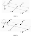
- FIG. 3f is a schematic diagram of a structure of the support 53 in FIG. 3b .
- a structure of a support may be a mechanical part having a groove.
- FIG. 3f shows an arc structure of the groove 531 on the support 53.
- a side of the groove may be set to a sawtooth shape.
- the flexible printed circuit board 41 and the cable 42 may be located at two ends of the support 53, as shown in FIG.
- a center of the groove 531 that is on the support 53 and that is used to clamp the cable 42 may face a side away from the flexible printed circuit board 41.
- the groove 531 has a specific angle, after the cable 42 is fastened in the groove 531, a bending direction of the cable 42 is fixed by a shape of the groove 531. Therefore, in a process of folding the terminal device, a degree of bending freedom of the cable 42 can be reduced, friction between the cable 42 and another component of the third housing 3 (for example, an inner surface or a bearing of the third housing 3) can be reduced, and friction generated by the cable 42 can also be reduced. Further, because the center of the groove 531 faces the end away from the flexible printed circuit board 41, friction between the cable 42 and the flexible printed circuit board 41 can be reduced in a bending process of the cable 42.
- a groove is disposed on a first surface 540 of the support (the first surface of the support is a surface of the support that is relatively far away from the screen), to place the cable, and the flexible printed circuit board is placed on a second surface of the support (the second surface of the support is a surface of the support that is relatively close to the screen; in FIG. 3f , because the second surface is opposite to the first surface 540, the second surface cannot be seen in FIG. 3f , and therefore the second surface is not shown in FIG. 3f ).
- a step structure 538 may be disposed on the second surface of the support, to reduce displacement of the flexible printed circuit board towards the cable, so as to reduce friction between the cable and the flexible printed circuit board support.
- the support 53 further includes stop blocks 535.
- the stop blocks 535 may be disposed on a surface of the support 53 that faces the first magnetic component 51, and the stop blocks 535 may be disposed at two sides of the support 53.
- the stop blocks 535 may be some protruding structural blocks disposed at two sides of the support 53.
- the stop blocks 535 are located at two sides of the first magnetic component 51. When the magnetic assembly moves leftward or rightward, the stop blocks 535 are blocked by the first magnetic component 51, so as to limit a movement amount of the magnetic assembly in a horizontal direction.
- a movement amount of the wire in the horizontal direction shown in FIG. 3a may be limited. This can alleviate a problem that the wire moves a lot in the horizontal direction caused by pulling the wire in the process of folding the terminal device, and further stabilize a form of the wire inside the third housing 3.
- the horizontal direction mentioned in this embodiment of this application is a direction perpendicular to the center line of the third housing 3 on a plane formed by a screen 12 when the terminal device is in the expanded state.
- FIG. 3b to FIG. 3f are described by using an example in which the groove 531 is disposed on the support 53.
- a structure used to fasten the cable 42 on the support 53 may be set as a fastener assembly.
- FIG. 3g to FIG. 3k an example in which a structure used to fasten the cable 42 on the support 53 in FIG. 2a is a fastener assembly is used for illustration, and detailed description is provided below.
- FIG. 3g is an exploded view of an internal structure of a third housing of another terminal device according to an embodiment of this application.
- an internal structure of an intermediate housing area of the terminal device can be seen more clearly in a form of the exploded view.
- the fastener assembly of the support 53 includes two parts, which are respectively a fastener 533 and a hole 534.
- a structural form that a cable is placed on a hole can be seen from FIG. 3g .
- the fastener 533 is not clamped to the hole 534.
- the hole 534 may be a rectangular hole, and the fastener 533 may be a mechanical part with ears at both ends.
- FIG. 3h is a schematic diagram of a structure in a direction C obtained after an outer housing, the first magnetic component 51, and the buffer component 6 in FIG. 3g are removed. That is, FIG. 3h is a schematic diagram of a structure of a rear side of the support. A rear side structure of the fastener and a rear side structure of the support can be seen from FIG. 3h . As shown in FIG. 3h , a flexible printed circuit board is laid on the rear side of the support, and a tail end of the support (the tail end of the support refers to an opposite end of an end at which the hole is disposed) slightly exceeds a width of the flexible printed circuit board. This can provide more protection for the flexible printed circuit board.
- the cable 42 when the cable 42 is fastened to the fastener assembly of the support 53, the cable 42 may be fastened to the fastener assembly in an arc angle.
- the flexible printed circuit board 41 and the cable 42 are located at two ends of the support 53, and a center of the arc of the cable 42 may face a side away from the flexible printed circuit board 41. In this way, because the cable 42 has a specific angle, after the cable 42 is fastened to the fastener assembly, a bending direction of the cable 42 is fixed.
- a degree of bending freedom of the cable 42 can be reduced, friction between the cable 42 and another component of the third housing 3 (for example, an inner surface or a bearing of the third housing 3) can be reduced, and friction generated by the cable 42 can also be reduced. Further, because the center of the arc of the cable 42 faces the end away from the flexible printed circuit board 41, friction between the cable 42 and the flexible printed circuit board 41 can be reduced in a bending process of the cable 42. In addition, a distance between the fastener assembly of the support 53 and the flexible printed circuit board 41 fastened on the support 53 may be increased.
- the groove 531 and the fastener assembly that are used to fasten the cable 42 are merely two examples.
- another structure that can fasten the cable 42 may also be disposed on the support 53.
- FIG. 3i is a schematic diagram of a structure obtained after the fastener 533 is clamped to the hole 534.
- the cable 42 is placed on the hole 534, and the fastener 533 is clamped to the hole 534, so that the cable 42 is clamped.
- FIG. 3i shows a structural form after the fastener 533 is clamped to the hole 534, and ears on two sides of the fastener 533 may be inserted into the hole 533, so that the fastener 533 is clamped to the hole 534.
- FIG. 3j is a schematic diagram of a structure of the support 53 in FIG. 3g .
- the stop blocks 535 are disposed on the first surface 540 (the first surface 540 is a surface that is relatively close to the first magnetic component) of the support.
- the stop blocks 535 refer to the foregoing content. Details are not described herein again.
- FIG. 3k is a schematic diagram of a structure of the support 53 in a direction C in FIG. 3g .
- a structural form of a second surface 541 of the support can be seen from FIG. 3k .
- one end of the support 53 is provided with the hole, and an arc-shaped boss structure 539 may be provided at the end provided with the hole.
- a center of the arc-shaped boss structure 539 faces one end away from the flexible printed circuit board 41.
- FIG. 3l is a schematic diagram of a structure of a screen side in FIG. 2a .
- a screen side of the third housing 3 includes the first inner housing 35, the second inner housing 351, and the third inner housing 352.
- the first inner housing 35 is rotatably connected to the second inner housing 351, and the first inner housing 35 is rotatably connected to the third inner housing 351.
- the second inner housing 351 and the third inner housing 352 are respectively disposed at both sides of the first inner housing 35.
- the second inner housing 351 is connected to the first housing 1, and the third inner housing 352 is connected to the second housing 2.
- the buffer component 6 penetrates inside the third housing, and is laid in the first housing 1 and the second housing 2.
- the screen 12 is further laid on the first inner housing 35, the second inner housing 351, the third inner housing 352, and the buffer component of the third housing.
- FIG. 3m is a schematic diagram of a structure of the terminal device in FIG. 3m in a folded state.
- the first inner housing 35, the second inner housing 351, and the third inner housing 352 may form relatively large space, to reserve specific space for a folded area of the screen 12, so that the screen 12 can be in a natural state as much as possible.
- FIG. 3n is a schematic diagram of a structure of another terminal device in a folded state. It can be seen from FIG. 3n that, if only one first inner housing 35 is disposed on the third housing, the first inner housing 35 is directly connected to the first housing 1 and the second housing 2, and the second inner housing 351 and the third inner housing 352 are no longer disposed. It can be seen from FIG. 3n that, when the terminal device is in the folded state, space reserved by the first inner housing 35, the first housing 1, and the second housing 2 in the folded area of the screen 12 is relatively small, and the first housing 1 and the second housing 2 are prone to squeeze onto the screen 12. In this solution, a damage rate of the screen 12 is relatively high. In the solutions provided in this embodiment of this application shown in FIG.
- One end of the wire may be fastened to the first housing 1, and the other end of the wire may be fastened to the second housing 2.
- the wire may be fastened in a plurality of manners.
- a manner in which the wire is fastened to the first housing 1 is used as an example.
- a steel sheet 7 is fastened between the flexible printed circuit board 41 and the first housing 1, foam 8 and a presser 9 are placed on a top surface of the flexible printed circuit board 41 at a time, and the presser 9 is configured to press the flexible printed circuit board 41 tightly.
- the presser 9, the foam 8, the flexible printed circuit board 41, and the steel sheet 7 may be fastened to the first housing 1 by using screws or the like.
- a double-sided tape may be placed between the steel sheet 7 and the first housing 1, to further fasten the steel sheet 7 and play a buffering role.
- the foam 8 is configured to reduce abrasion between the wire and the presser 9, and plays a buffering role.
- a positioning hole may be preset on the first housing 1, and is configured to play a positioning role in a process of fastening the flexible printed circuit board 41 to the first housing 1. In other words, the positioning hole is configured to insert a fastening connector such as a screw.
- the cable 42 when the wire includes the cable 42, the cable 42 may be disposed between the steel sheet 7 and the presser 9, and the cable 42 disposed between the steel sheet 7 and the presser 9 is fastened to the first housing 1. Further, the presser 9, the cable 42, and the steel sheet 7 may be fastened to the first housing 1 by using screws or the like.
- the foam 8 may be disposed between the steel sheet 7 and the cable 42 for buffering. In this embodiment of this application, the foam 8 may alternatively be replaced with another rubber buffer material.
- a double-sided tape may be disposed between the steel sheet 7 and the first housing 1, to further fasten the steel sheet 7 and play a buffering role.
- the cable groove 531 may also be disposed on the first housing 1, and the cable groove 531 may be optionally disposed in an oblique direction, to match a bending form of the arc-shaped cable 42 fastened to the third housing 3.
- the cable 42 is fastened in the oblique cable groove 531, and the cable 42 may be glued to the oblique cable groove 531 through glue dispensing.
- a direction of the cable 42 fastened in the oblique cable groove 531 matches an arc shape of the cable 42 fastened by the support 53, so that the cable 42 is bent more naturally, abrasion of the cable 42 is reduced, and reliability of the cable 42 is further improved.
- the first housing 1 is used as an example for description.
- the wire is also fastened on the first housing 1 and the second housing 2, that is, on both sides of the third housing 3. Therefore, the degree of freedom of the wire may be further limited, a movement form of the wire may be further limited, and abrasion between the wire and the third housing 3 is further reduced.
- the wire may include one or more cables.
- one or more grooves may be disposed on the support, and a plurality of cables may be placed into one groove, or a plurality of cables may be placed into a plurality of grooves.
- one or more cables may be placed into one groove.
- one or more fastener assemblies may be disposed on the support. A plurality of cables are fastened by using the one or more fastener assemblies, and one fastener assembly may fasten one or more cables.
- the flexible printed circuit board included in the wire may be a single-layer flexible printed circuit board, or may include a multilayer flexible printed circuit board. That is, one or more layers of flexible printed circuit boards 41 may be included between the support 53 and the second magnetic component 54.
- the wire includes a single-layer flexible printed circuit board 41
- the flexible printed circuit board is disposed between the support and the second magnetic component. Because the flexible printed circuit board 41 is clamped between the support 53 and the second magnetic component 54 under an effect of a magnetic adsorption force between the second magnetic component 54 and the first magnetic component 51, the flexible printed circuit board 41 may be in movable contact with the support 53. In this way, in the process of folding and expanding the terminal device, relative movement may exist between the flexible printed circuit board and the support. In this way, if there is an assembly tolerance, the structural form more easily absorbs the tolerance, so that lengths of the flexible printed circuit boards 41 on the left and right sides of the wire fastening assembly 5 can be more optimized.
- the flexible printed circuit board 41 is in movable contact with the second magnetic component 54.
- relative movement may exist between the flexible printed circuit board and the second magnetic component.
- the structural form more easily absorbs the tolerance, so that lengths of the flexible printed circuit boards 41 on the left and right sides of the wire fastening assembly 5 can be more optimized.
- the flexible printed circuit board included in the wire may be a single-layer flexible printed circuit board, or may include a multilayer flexible printed circuit board. That is, one or more layers of flexible printed circuit boards 41 may be included between the support 53 and the second magnetic component 54.
- the wire includes a single-layer flexible printed circuit board 41
- the flexible printed circuit board is disposed between the support and the second magnetic component. Because the flexible printed circuit board 41 is clamped between the support 53 and the second magnetic component 54 under an effect of a magnetic adsorption force between the second magnetic component 54 and the first magnetic component 51, the flexible printed circuit board 41 may be connected to the support 53 by using, for example, an adhesive or a double-sided tape. In this way, in the process of folding and expanding the terminal device, the flexible printed circuit board and the support, and the flexible printed circuit board and the second magnetic component are adhered to each other by using the adhesive, and therefore are relatively evenly distributed on two sides.
- the flexible printed circuit board 41 is connected to the second magnetic component 54 by using, for example, the adhesive or the double-sided tape.
- the flexible printed circuit board and the support, and the flexible printed circuit board and the second magnetic component are adhered to each other by using the adhesive, and therefore are relatively evenly distributed on two sides.
- any two layers of the multilayer flexible printed circuit board 41 may be in movable contact. In other words, there may be relative displacement between any two layers of the flexible printed circuit board 41, and relative movement may exist in the process of folding and expanding the terminal device.
- the multilayer flexible printed circuit boards 41 are fixedly connected by using the adhesive, the multilayer flexible printed circuit boards 41 that are bonded are relatively hard and thick. In this case, the multilayer flexible printed circuit boards 41 are prone to be broken and fail.
- the multilayer flexible printed circuit boards 41 are in movable contact with each other and do not need to be bonded by using the adhesive. In this way, a failure of the flexible printed circuit board 41 caused by the adhesive can be avoided, and reliability of the flexible printed circuit board 41 can be improved.
- the second magnetic component 54 and the flexible printed circuit board 41 that is in contact with the second magnetic component 54 may be in movable contact, and may have relative displacement. Relative movement may exist in the process of folding and expanding the terminal device. In this way, the flexible printed circuit board 41 can slide in the process of folding and expanding the terminal device. Therefore, if there is an assembly tolerance, the tolerance can be more easily absorbed, so that lengths of the flexible printed circuit boards 41 on the left and right sides of the wire fastening assembly 5 can be more optimized.
- the second magnetic component 54 may be connected, by using, for example, an adhesive, to the flexible printed circuit board 41 that is in contact with the second magnetic component 54. In this way, quantities on two sides of the flexible printed circuit board can be kept relatively even.
- the support 53 and the flexible printed circuit board 41 that is in contact with the support 53 may be in movable contact, and may have relative displacement. Relative movement may exist in the process of folding and expanding the terminal device. In this way, the flexible printed circuit board 41 can slide in the process of folding and expanding the terminal device. Therefore, if there is an assembly tolerance, the tolerance can be more easily absorbed, so that lengths of the flexible printed circuit boards 41 on the left and right sides of the wire fastening assembly 5 can be more optimized.
- the support 53 and the flexible printed circuit board 41 that is in contact with the support 53 may be connected by using, for example, the adhesive.
- quantities on two sides of the flexible printed circuit board can be kept relatively even.
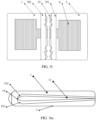
- FIG. 4a shows an example of a schematic diagram of a structure of a cable 42
- FIG. 4b shows an example of a schematic diagram of a structure of another cable 42
- the cable 42 includes a first positioning area 421, a second positioning area 422, and a third positioning area 423.
- the first positioning area 421 refers to an area in which the cable 42 is connected to the third housing 3
- the second positioning area 422 refers to an area in which the cable 42 is fixedly connected to the first housing 1
- the third positioning area 423 refers to an area in which the cable 42 is fixedly connected to the second housing 2.
- the cable 42 in the first positioning area 421, the second positioning area 422, and the third positioning area 423 may be thickened, to reduce a failure possibility of the cable 42 and improve reliability of the cable 42.
- a surface of the cable 42 in one or more of the first positioning area 421, the second positioning area 422, and the third positioning area 423 of the cable 42 may be wrapped with an acetate cloth tape or soft cloth, to thicken the cable 42, as shown in FIG. 4a , so as to improve reliability of the cable 42.
- the cable 42 may be manufactured by using a rubber (rubber) in-mold decoration technology.
- the cable 42 in one or more of the first positioning area 421, the second positioning area 422, and the third positioning area 423 of the cable 42 are thickened, as shown in FIG. 4b .
- a positioning structure may be disposed on the cable 42 in one or more of the first positioning area 421, the second positioning area 422, and the third positioning area 423 by thickening the cable 42.
- the cable 42 with a largest diameter in the first positioning area 421 belongs to the positioning structure of the first positioning area 421, and during assembly, the cable 42 with the largest diameter in the first positioning area 421 may be connected to the wire fastening assembly 5.
- a cross structure of the second positioning area 422 may be fixedly connected to the first housing 1 at the cross structure of the second positioning area 422 during positioning.
- a cross structure of the third positioning area 423 may be fixedly connected to the second housing 2 at the cross structure of the third positioning area 423 during positioning.
- the cable 42 can be more accurately positioned to the support 53, the first housing 1, and the second housing 2.
- the first positioning area 421 of the cable 42 is thickened, so that the cable 42 is clamped more tightly in the groove 531.
- the cable 42 may also be glued to the support 53 through glue dispensing.
- the cable 42 may be fastened in the groove 531 of the support 53 through glue dispensing.
- FIG. 4c shows an example of a schematic diagram of a structure of a terminal device.
- the first housing 1 in an area E is removed, so that a structure of the third housing 3 corresponding to the area E can be seen.
- the second housing 2 in an area F is removed, so that a structure of the third housing 3 corresponding to the area F can be seen.
- the third housing 3 includes the first opening 31 area and the second opening 32 area, and the flexible printed circuit board 41 and the cable 42 penetrate into the third housing 3 from the first opening 31 area and penetrate out from the second opening 32 area.
- an embodiment of this application provides an optional method for assembling the terminal device.
- the third housing 3 may be first assembled with the first housing 1, and the third housing 3 is assembled with the second housing 2.
- the buffer component 6 penetrates into the interior of the third housing 3 through the first opening 31 and the second opening 32, and the buffer component 6 is fastened to the first housing 1 and the second housing 2.
- the cable is connected to the magnetic assembly, and the magnetic assembly connected to the cable penetrates into the third housing 3 through the first opening 31, so that the magnetic assembly is automatically adsorbed on the first magnetic component 51 inside the third housing 3 (the first magnetic component 51 is pre-installed on the third housing 3).
- the cable is penetrated out from the second opening 32, and the cable is fastened to the first housing 1 and the second housing 2.
- the outer housing of the third housing 3 may be first assembled with the first housing 1, and the outer housing of the third housing 3 is assembled with the second housing 2.
- the buffer component 6 is fastened to the first housing 1 and the second housing 2.
- the cable is connected to the magnetic assembly, and the magnetic assembly connected to the cable penetrates into the third housing 3 through the first opening 31, so that the magnetic assembly is automatically adsorbed on the first magnetic component 51 inside the third housing 3 (the first magnetic component 51 is pre-installed on the third housing 3).
- the cable is penetrated out from the second opening 32.
- the buffer component 6 covers the interior of the third housing 3, and is fastened to the first housing 1 and the second housing 2.
- the first inner housing 35 of the third housing 3 is assembled. Then, the cable is fastened to the first housing 1, and the cable is fastened to the second housing 2.
Landscapes
- Engineering & Computer Science (AREA)
- Theoretical Computer Science (AREA)
- Computer Hardware Design (AREA)
- Human Computer Interaction (AREA)
- Physics & Mathematics (AREA)
- General Engineering & Computer Science (AREA)
- General Physics & Mathematics (AREA)
- Signal Processing (AREA)
- Computer Networks & Wireless Communication (AREA)
- Power Engineering (AREA)
- Telephone Set Structure (AREA)
- Insertion, Bundling And Securing Of Wires For Electric Apparatuses (AREA)
Description
- Priority is claimed to
Chinese Patent Application No. 201911190782.9, filed with the China National Intellectual Property Administration on November 28, 2019 - This disclosure generally relates to the communication field, and the invention in particular relates to a foldable terminal device.
- With upgrade of electronic products, display screens of various terminal devices such as mobile phones and tablet computers become larger. This is because a larger display screen can provide richer information for a user, improve man-machine communication efficiency, and bring better use experience. However, as a screen increases, an outline size of a base of a terminal device correspondingly increases; and as the size of the base of the terminal device increases, it is inconvenient to carry and place the terminal device. This restricts increasing of the size of the display screen.
- Currently, a foldable technology well finds a compromise between miniaturization development of a base of a terminal device and large-screen development of a display screen. For example, after being folded, a foldable mobile phone has a same size as a conventional mobile phone, and can be conveniently carried. When a screen is expanded, a screen with a very large display area can be obtained.
- A foldable terminal device has two housings, the two housings are connected by using a third housing, and a wire penetrates through an interior of the third housing and is connected to the two housings. In a process of folding and expanding the terminal device, the wire inside the third housing moves as the terminal device is folded and expanded. In the movement process, the wire is prone to scratch with another component, and consequently the wire is prone to wear.
-
US2018/324964A1 discloses an electronic device which comprise a first housing including a first surface and a second surface facing in a direction opposite the first surface, a second housing including a third surface and a fourth surface facing in a direction opposite the third surface, a hinge disposed between the first housing and the second housing configured to provide rotational motion between the first housing and the second housing, and a flexible display disposed from the first surface of the first housing across the hinge to the third surface of the second housing, at least part of the flexible display configured to form a curved surface as the hinge structure is folded, wherein the hinge may include dual-axis hinges configured to provide a first rotational axis allowing the first housing to rotate about the second housing and a second rotational axis allowing the second housing to rotate about the first housing and slides coupled with the first housing and the second housing and configured to provide sliding motion perpendicular to a lengthwise direction of the first housing and the second housing. -
CN208609020U discloses a foldable electronics, comprising: rotary shaft rack, including bottom plate and the first side plate and the second side plate that are connected to bottom plate opposite sides, bottom plate, the first, second side plate enclose and set to form accommodation space; First shell and second shell can turn around bracing strut rotation; Flexible screen, including the first area, intermediate region and second area being wholely set, first area is arranged in conjunction with first shell, and second area is arranged in conjunction with second shell, and intermediate region corresponds to the bottom plate of rotary shaft rack; And guide member, it is set between the intermediate region of flexible screen and rotary shaft rack, for applying the guiding force towards the accommodation space of rotary shaft rack to intermediate region. In the initial stage that foldable electronic switches from unfolded state to folded state, guide member keeps the intermediate region stress of flexible screen clear, and then deforms flexible screen towards predetermined direction, avoids flexible screen impaired. -
US2015/233162A1 discloses a foldable display apparatus. The foldable display apparatus includes a flexible display panel, first body configured to support a left portion of a flexible display panel, and second body configured to support a right portion of the flexible display panel, first and second frames configured to surround portions of outlines of the first and second bodies, a hinge member configured to hinge-connect the first and second frames with each other in a foldable manner, and first and second supports having sides hinge-connected to the first and second frames, and configured to form an accommodation space in which a folded portion of the flexible display panel is folded to form a curvature at a first position at which the first and second bodies are folded, and to support the folded portion of the flexible display panel at a second position at which the first and second bodies are unfolded -
CN209390110U discloses a kind of electronic equipment, including first shell, second shell, third shell, flexible screen, first rotating shaft and the first RF transmit-receive circuit, flexible screen includes sequentially connected first fixed area, folding region and the second fixed area, first fixed area is fixed on first shell, second fixed area is fixed on second shell, third shell includes the first side being oppositely arranged and second side, accommodating space is formed between first side and second side, first shell is rotationally connected with the first side by first rotating shaft, second shell is rotationally connected with second side, so that face accommodating space when being in flat at least partially in electronic equipment of folding region, folding region is contained in accommodating space when being in folded state at least partially in electronic equipment; First rotating shaft is equipped with the first irradiation unit, and the first RF transmit-receive circuit is set at least one of first shell, second shell and third shell, and the first RF transmit-receive circuit is electrically connected the first irradiation unit. -
CN106707577A discloses a display screen module and a terminal. The display screen module comprises a flexible circuit board, a display driving chip and an overall fixing part used for being matched with a middle frame fixing part on a terminal middle frame. Through the cooperation of the overall fixing part and the middle frame fixing part, fixation of the relative positions of the display screen module and the terminal middle frame can be achieved, it is guaranteed that the display screen module does not shift after the terminal is assembled, then the position of the display driving chip in the terminal is fixed. - The object of the invention is to provide a foldable terminal device in which a wire of the foldable terminal device is fastened to a third housing, to reduce abrasion of the wire. This object is solved by the attached independent claims and further embodiments and improvements of the invention are listed in the attached dependent claims. Hereinafter, up to the "brief description of the drawings", expressions like "...aspect according to the invention", "according to the invention", or "the present invention", relate to technical teaching of the broadest embodiment as claimed with the independent claims. Expressions like "implementation", "design", "optionally", "preferably", "scenario", "aspect" or similar relate to further embodiments as claimed, and expressions like "example", "...aspect according to an example", "the disclosure describes", or "the disclosure" describe technical teaching which relates to the understanding of the invention or its embodiments, which, however, is not claimed as such.
- According to a first aspect according to the invention, the invention provides a foldable terminal device, including a first housing, a second housing, a third housing, a wire, and a wire fastening assembly. Two rotating shafts are respectively disposed at both ends of the third housing, one side of the third housing is connected to the first housing through the two rotating shafts, the other side of the third housing is connected to the second housing through the two rotating shafts, at least one of the first housing and the second housing is rotatably connected to the third housing, the third housing is a semi-closed housing, a non-closed area of the third housing is provided with an opening area, and the wire fastening assembly is disposed between the two rotating shafts of the third housing. The wire penetrates through an interior of the third housing through the opening area of the third housing, the wire is connected to the wire fastening assembly inside the third housing, and both ends of the wire are respectively connected to the first housing and the second housing. The wire fastening assembly includes a first magnetic component and a magnetic assembly, the first magnetic component is fixedly connected to the interior of the third housing, the magnetic assembly is connected to the wire, and the magnetic assembly is magnetically connected to the first magnetic component. Because the wire located in the third housing is fastened by using the wire fastening assembly, a degree of freedom of the wire in the third housing can be reduced, so that a movement amount of the wire in the third housing can be reduced, a degree of abrasion of the wire can be reduced, and there are less worn parts of the wire. In a process of assembling the terminal device, the first magnetic component may be fixedly connected to the interior of the
third housing 3 in advance. In the assembly process, the wire is connected to the magnetic assembly, and the magnetic assembly connected to the wire penetrates into the third housing from the first opening. Because there is a magnetic adsorption force between the magnetic assembly and the first magnetic component, after being placed into thethird housing 3, the magnetic assembly automatically adsorbs on the first magnetic component. Then, the other end of the wire penetrates out from the second opening. It can be learned that, in this operation process, automatic positioning of the magnetic assembly and the first magnetic component is implemented, and installation is relatively convenient. - In a possible implementation, the magnetic assembly includes a second magnetic component. The second magnetic component is connected to the first magnetic component; and the wire is disposed between the first magnetic component and the second magnetic component. In this way, the wire may be clamped by using a magnetic adsorption force between the first magnetic component and the second magnetic component. This structure is relatively simple and is easy to implement.
- In a possible implementation, the magnetic assembly further includes a support. The support is disposed between the second magnetic component and the first magnetic component. The wire includes a flexible printed circuit board, and the flexible printed circuit board is disposed between the support and the second magnetic component. The flexible printed circuit board is in contact with or connected to the support. The flexible printed circuit board is in contact with or connected to the second magnetic component. In this way, in the assembly process, the wire may be first fastened by using the support and the second magnetic component, and then the support and the second magnetic component that are used to fasten the wire are inserted into an intermediate housing from the opening area, so that a fastening position of the wire can be more accurately determined.
- In a possible implementation, the wire includes a multilayer flexible printed circuit board, and the multilayer flexible printed circuit board is disposed between the support and the second magnetic component. The multilayer flexible printed circuit board satisfies one or more of the following content: Two adjacent layers of flexible printed circuit boards in the multilayer flexible printed circuit board are in contact (or referred to as movable contact) with each other. A flexible printed circuit board in the multilayer flexible printed circuit board that is in contact with the support is in contact (or referred to as movable contact) with or connected to the support. A flexible printed circuit board in the multilayer flexible printed circuit board that is in contact with the second magnetic component is in contact with or connected to the second magnetic component.
- Therefore, the multilayer flexible printed circuit board in this embodiment of this application may be in contact (or referred to as movable contact), and do not need to be bonded by using an adhesive. This can avoid failure of the flexible printed circuit board caused by the adhesive, and improve reliability of the flexible printed circuit board. In addition, when the flexible printed circuit board in the multilayer flexible printed circuit board that is in contact with the support is in contact with the support, the flexible printed circuit board can slide in a process of folding and expanding the terminal device. Therefore, if there is an assembly tolerance, the tolerance can be more easily absorbed, so that lengths of the flexible printed circuit boards on the left and right sides of the wire fastening assembly can be more optimized. In addition, when the flexible printed circuit board in the multilayer flexible printed circuit board that is in contact with the second magnetic component is in contact with the second magnetic component, the flexible printed circuit board can slide in the process of folding and expanding the terminal device. Therefore, if there is an assembly tolerance, the tolerance can be more easily absorbed, so that lengths of the flexible printed circuit boards on the left and right sides of the wire fastening assembly can be more optimized. In another aspect, when the flexible printed circuit board in the multilayer flexible printed circuit board that is in contact with the second magnetic component is connected to the second magnetic component by using, for example, an adhesive or a double-sided tape, this can prevent the flexible printed circuit board from moving excessively unevenly on the left and right sides. In still another aspect, when the flexible printed circuit board in the multilayer flexible printed circuit board that is in contact with the support is connected to the support by using, for example, an adhesive or a double-sided tape, this can prevent the flexible printed circuit board from moving excessively unevenly on the left and right sides.
- In a possible implementation, the wire includes a cable, and the cable is disposed on a plane of the support that faces the second magnetic component, or the cable is disposed on a plane of the support that faces the first magnetic component. The flexible printed circuit board is disposed at one end of the support, and the cable is disposed at the other end of the support. A distance between a first contact area and a second contact area that are on the support is greater than a preset distance, the first contact area includes a contact area between the flexible printed circuit board and the support, and the second contact area includes a contact area between the cable and the support. In this implementation, friction between the cable and the flexible printed circuit board in a bending process can be further reduced.
- In a possible implementation, an arc groove is disposed on the support, and the cable is clamped to the arc groove. A center of the arc groove faces an end away from the flexible printed circuit board. In this way, a bending direction of the cable is fixed by a shape of the groove. Therefore, in a process of folding the terminal device, a degree of bending freedom of the cable can be reduced, friction between the cable and another component of the third housing (for example, an inner surface or a bearing of the third housing) can be reduced, and friction between the cable and the flexible printed circuit board can be reduced.
- In a possible implementation, a fastener assembly is disposed on the support, the cable is clamped to the fastener assembly, the cable presents an arc in the fastener assembly, and a center of the arc presented by the cable in the fastener assembly faces the end away from the flexible printed circuit board. In this way, a bending direction of the cable is fixed by the fastener assembly. Therefore, in a process of folding the terminal device, a degree of bending freedom of the cable can be reduced, friction between the cable and another component of the third housing (for example, an inner surface or a bearing of the third housing) can be reduced, and friction between the cable and the flexible printed circuit board can be reduced.
- In a possible implementation, stop blocks are disposed on a surface of the support that faces the first magnetic component, and the stop blocks are disposed at both sides of the first magnetic component. In this way, when the magnetic assembly moves leftward or rightward, the stop blocks are blocked by the first magnetic component, so as to limit a movement amount of the magnetic assembly in a horizontal direction.
- In a possible implementation, the terminal device further includes: a buffer component, where the buffer component penetrates between the magnetic assembly and the third housing. In this way, friction and scratches between the wire and a first inner housing can be reduced. In addition, when the terminal device is in an expanded state, the buffer component presents a multidimensional wave shape. In this way, a redundancy of the wire inside the third housing can be better and more naturally absorbed when the terminal device is in the expanded state.
- In a possible but not claimed implementation, a difference between a line length between the wire fastening assembly and the first housing and a line length between the wire fastening assembly and the second housing is within a preset range. In this way, the redundancy of the wire may be relatively evenly allocated to both sides of the wire fastening assembly.
- In a possible but not claimed implementation, the wire includes the cable, and the cable is made by using a rubber in-mold decoration technology. A diameter of an area that is on the cable and connected to the third housing, the first housing, and the second housing is greater than a preset diameter. A positioning structure is disposed in the area that is on the cable and connected to the third housing, the first housing, and the second housing. In this way, the cable can be more accurately positioned to the support, the first housing, and the second housing, and a service life of the cable can be increased by increasing a diameter of a contact area between the cable and another component.
- In a possible but not claimed implementation, an upper surface of the third housing includes a first inner housing, a second inner housing, and a third inner housing, and the upper surface of the third housing includes a surface on which a screen of the terminal device is laid; the second inner housing and the third inner housing are located at both sides of the first inner housing; one side of the second inner housing is rotatably connected to the first inner housing, and the other side is connected to the first inner housing; and one side of the third inner housing is rotatably connected to the first inner housing, and the other side is connected to the second inner housing. In this way, when the terminal device is in the folded state, the first inner housing, the second inner housing, and the third inner housing may form relatively large space, to reserve specific space for a folded area of the screen, so that the screen can be in a natural state as much as possible.
- According to a second but not claimed aspect, an embodiment of this application provides a foldable terminal device, including a first housing, a second housing, a third housing, a wire, a wire fastening assembly, and a buffer component. Two rotating shafts are respectively disposed at both ends of the third housing, one side of the third housing is connected to the first housing through the two rotating shafts, the other side of the third housing is connected to the second housing through the two rotating shafts, at least one of the first housing and the second housing is rotatably connected to the third housing, the third housing is a semi-closed housing, a non-closed area of the third housing is provided with an opening area, one side or a plurality of sides of the opening area is or are designed with a rounded corner, a diameter of the rounded corner is greater than a preset diameter, a wire fastening assembly is disposed between the two rotating shafts of the third housing, and a wire is fastened to the wire fastening assembly.
- An upper surface of the third housing includes a first inner housing, a second inner housing, and a third inner housing, and the upper surface of the third housing includes a surface on which a screen of the terminal device is laid; the second inner housing and the third inner housing are located at both sides of the first inner housing; one side of the second inner housing is rotatably connected to the first inner housing, and the other side is connected to the first housing; and one side of the third inner housing is rotatably connected to the first inner housing, and the other side is connected to the second housing.
- The wire includes a cable and a multilayer flexible printed circuit board. The wire penetrates through an interior of the third housing through the opening area of the third housing, both ends of the wire are respectively connected to the first housing and the second housing, the cable is made by using a rubber in-mold decoration technology, a diameter of an area that is on the cable and connected to the third housing, the first housing, and the second housing is greater than a preset diameter, and a positioning structure is disposed in the area that is on the cable and connected to the third housing, the first housing, and the second housing.
- A difference between a line length between the wire fastening assembly and the first housing and a line length between the wire fastening assembly and the second housing is within a preset range. The wire fastening assembly includes a first magnetic component, a second magnetic component, and a support. The first magnetic component is fixedly connected to the interior of the third housing. The second magnetic component is magnetically connected to the first magnetic component. The support is disposed between the second magnetic component and the first magnetic component. Stop blocks are disposed on a surface of the support that faces the first magnetic component, and the stop blocks are disposed at both sides of the first magnetic component.
- An arc groove is disposed on the support, the cable is clamped to the arc groove, and a center of the arc groove faces an end away from the multilayer flexible printed circuit board. Alternatively, a fastener assembly is disposed on the support, the cable is clamped to the fastener assembly, the cable presents an arc in the fastener assembly, and a center of the arc presented by the cable in the fastener assembly faces the end away from the multilayer flexible printed circuit board. The multilayer flexible printed circuit board is disposed at one end of the support, a multilayer cable is disposed at the other end of the support, a distance between a first contact area and a second contact area that are on the support is greater than a preset distance, the first contact area includes a contact area between the flexible printed circuit board and the support, and the second contact area includes a contact area between the cable and the support.
- The multilayer flexible printed circuit board is disposed between the support and the second magnetic component, two adjacent layers of flexible printed circuit boards in the multilayer flexible printed circuit board are in contact (or referred to as movable contact) with each other. A flexible printed circuit board in the multilayer flexible printed circuit board that is in contact with the support is in contact with or connected to the support. A flexible printed circuit board in the multilayer flexible printed circuit board that is in contact with the second magnetic component is in contact with or connected to the second magnetic component. The buffer component penetrates between the magnetic assembly and the third housing, and when the terminal device is in an expanded state, the buffer component presents a multidimensional wave shape.
- Because the wire located in the third housing is fastened by using the wire fastening assembly, a degree of freedom of the wire in the third housing can be reduced, so that a movement amount of the wire in the third housing can be reduced, a degree of abrasion of the wire can be reduced, and there are less worn parts of the wire. In a process of assembling the terminal device, the first
magnetic component 51 may be fixedly connected to the interior of thethird housing 3 in advance. In the assembly process, the wire is connected to the magnetic assembly, and the magnetic assembly connected to the wire penetrates into thethird housing 3 from thefirst opening 31. Because there is a magnetic adsorption force between the magnetic assembly and the firstmagnetic component 51, after being placed into thethird housing 3, the magnetic assembly automatically adsorbs on the firstmagnetic component 51. Then, the other end of the wire penetrates out from thesecond opening 32. It can be learned that, in this operation process, automatic positioning of the magnetic assembly and the firstmagnetic component 51 is implemented, and installation is relatively convenient. Further, one side or a plurality of sides of the opening area is or are designed with the rounded corner, and the diameter of the rounded corner is greater than the preset diameter. This can make peripheries of the first opening and the second opening that are in contact with the wire smoother, thereby further reducing a degree of abrasion of the wire. - In the following description, features which in the above summary of the invention have been marked as "not claimed" or "according to the invention" are also hereinafter, when they are described and explained with reference to the drawings, to be understood as "not claimed" or "not part of the invention" or "according to the invention".
-
-
FIG. 1a is a schematic diagram of a structure of a terminal device in a folded state according to an embodiment of this application; -
FIG. 1b is a schematic diagram of a structure of a terminal device in an expanded state according to an embodiment of this application; -
FIG. 2a is a schematic diagram of a structure of a terminal device from which a part of a first housing and a part of a second housing inFIG. 1b are removed; -
FIG. 2b is a schematic diagram of a structure of a terminal device after awire fastening assembly 5 inFIG. 2a is removed; -
FIG. 3a is a schematic cross-sectional view in a direction D inFIG. 2a ; -
FIG. 3b is an exploded view of an internal structure of a third housing of a terminal device according to an embodiment of this application; -
FIG. 3c is a schematic diagram of a structure obtained after an outer housing and a first magnetic component inFIG. 3b are removed; -
FIG. 3d is a partial enlarged diagram of an area A inFIG. 3c ; -
FIG. 3e is a view shown in a direction B inFIG. 3b ; -
FIG. 3f is a schematic diagram of a structure of a support inFIG. 3b ; -
FIG. 3g is an exploded view of an internal structure of a third housing of another terminal device according to an embodiment of this application; -
FIG. 3h is a schematic diagram of a structure in a direction C obtained after an outer housing, a first magnetic component, and a buffer component inFIG. 3g are removed; -
FIG. 3i is a schematic diagram of a structure obtained after a fastener is clamped to a hole; -
FIG. 3j is a schematic diagram of a structure of a support inFIG. 3g ; -
FIG. 3k is a schematic diagram of a structure of a support in a direction C inFIG. 3g ; -
FIG. 3l is a schematic diagram of a structure of an upper surface inFIG. 2a ; -
FIG. 3m is a schematic diagram of a structure of a terminal device inFIG. 3l in a folded state; -
FIG. 3n is a schematic diagram of a structure of another terminal device in a folded state; -
FIG. 4a is a schematic diagram of a structure of acable 42; -
FIG. 4b is a schematic diagram of a structure of anothercable 42; and -
FIG. 4c is a schematic diagram of a structure of a terminal device according to an embodiment of this application. -
- 1-First housing
- 11-First threaded hole
- 12-Screen
- 2-Second housing
- 21-Second threaded hole
- 3-Third housing
- 31-First opening
- 32-Second opening
- 33-Rotating shaft
- 34-Outer housing
- 35-First inner housing
- 351-Second inner housing
- 352-Third inner housing
- 41-Flexible printed circuit board
- 42-Cable
- 421-First positioning area
- 422-Second positioning area
- 423-Third positioning area
- 5-Wire fastening assembly
- 51-First magnetic component
- 53-Support
- 531-Groove
- 533-Fastener
- 534-Hole
- 535-Stop block
- 536-First contact area
- 537-Second contact area
- 538-Step structure
- 539-Boss structure
- 540-First surface
- 541-Second surface
- 54-Second magnetic component
- 6-Buffer component
- 7-Steel sheet
- 8-Foam
- 9-Presser
- A terminal device in embodiments of this application is a foldable device. The terminal device in embodiments of this application may include a device that provides a user with voice and/or data connectivity, for example, a handheld device with a wireless connection function, or a processing device connected to a wireless modem. The terminal device may communicate with a core network through a radio access network (radio access network, RAN), and exchange a voice and/or data with the RAN. The terminal device may include user equipment (user equipment, UE), a wireless terminal device, a mobile terminal device, a device-to-device (device-to-device, D2D) communication terminal device, a V2X terminal device, a machine-to-machine/machine-type communication (machine-to-machine/machine-type communication, M2M/MTC) terminal device, an internet of things (internet of things, IoT) terminal device, a subscriber unit (subscriber unit), a subscriber station (subscriber station), a mobile station (mobile station), a remote station (remote station), an access point (access point, AP), a remote terminal (remote terminal), an access terminal (access terminal), a user terminal (user terminal), a user agent (user agent), a user device (user device), or the like. For example, the terminal device may include a mobile phone (or referred to as a "cellular" phone), a computer with a mobile terminal device, or a portable, pocket-sized, handheld, or computer built-in mobile apparatus, for example, a device such as a personal communication service (personal communication service, PCS) phone, a cordless phone, a session initiation protocol (session initiation protocol, SIP) phone, a wireless local loop (wireless local loop, WLL) station, or a personal digital assistant (personal digital assistant, PDA). The terminal device further includes a limited device, for example, a device with low power consumption, a device with a limited storage capacity, or a device with a limited computing capability. For example, the terminal device includes an information sensing device such as a barcode, radio frequency identification (radio frequency identification, RFID), a sensor, a global positioning system (global positioning system, GPS), or a laser scanner.
-
FIG. 1a shows an example of a schematic diagram of a structure of a terminal device in a folded state according to an embodiment of this application. When the terminal device is in the folded state, a screen of the terminal device may be folded.FIG. 1b shows an example of a schematic diagram of a structure of the terminal device in an expanded state according to this embodiment of this application. When the terminal device is in the expanded state, the screen is in an expanded state. In this embodiment of this application, one side that is of the terminal device in the expanded state and on which the screen is located is referred to as a screen side, and the other side opposite to the screen side is referred to as a housing side.FIG. 1b shows a schematic diagram of a structure of the housing side of the terminal device in the expanded state, that is, a schematic diagram of a structure of a side opposite to the screen side of the terminal device. In this embodiment of this application, the expanded state may also be referred to as an unfolded state. - As shown in
FIG. 1a , when the terminal device is in the folded state, a part of a side surface of athird housing 3 is exposed (as shown in the figure, the part of thethird housing 3 is exposed, and in actual application, another component may be used to block the exposed part of the third housing 3). As shown inFIG. 1b , when the terminal device is in the expanded state, thethird housing 3 on the housing side of the terminal device is blocked by afirst housing 1 and a second housing 2 (in the figure, an example in which the third housing is completely blocked by thefirst housing 1 and thesecond housing 2 is used for illustration, and in actual application, when the terminal device is in the expanded state, thethird housing 3 may not be completely blocked by thefirst housing 1 and the second housing 2). InFIG. 1b , thethird housing 3 is indicated by using a dashed line. As shown inFIG. 1b , some first threadedholes 11 are further disposed on the third housing, and are configured to connect thethird housing 3 to thefirst housing 1. Some second threadedholes 21 are disposed on thesecond housing 2, and are configured to connect thethird housing 3 to thesecond housing 2. A component such as a battery cover or a small screen may be covered above a side that is of the third housing and on which the first threadedhole 11 and the second threadedhole 21 are disposed, and the covered component such as the battery cover or the small screen may block the first threadedhole 11 and the second threadedhole 21. - To show an internal structure of the terminal device more clearly,
FIG. 2a shows an example of a schematic diagram of a structure of the terminal device from which a part of thefirst housing 1 and a part of thesecond housing 2 inFIG. 1b are removed. As shown inFIG. 2a , after the part of the first housing and the part of the second housing are removed, the blockedthird housing 3 and a wire can be seen. InFIG. 2a , the terminal device includes thefirst housing 1, thesecond housing 2, thethird housing 3, the wire, and awire fastening assembly 5. InFIG. 2a , the wire is shown by using a flexible printedcircuit board 41 and acable 42 as an example. In a specific embodiment, the wire may include the flexible printedcircuit board 41 and/or thecable 42. - As shown in
FIG. 2a , two rotatingshafts 33 may be respectively disposed at both ends of thethird housing 3. The rotatingshaft 33 is disposed inside thethird housing 3, and is indicated by using a dashed line inFIG. 2a . One side of thethird housing 3 may be connected to thefirst housing 1 through the rotatingshaft 33, the other side of the third housing may be connected to thesecond housing 2 through the rotatingshaft 33, and at least one of thefirst housing 1 and thesecond housing 2 is rotatably connected to thethird housing 3 through the rotatingshaft 33. To show the internal structure of the terminal device more clearly, a part of thefirst housing 1 and a part of thesecond housing 2 are removed inFIG. 2a . - As shown in
FIG. 2a , thethird housing 3 may be a semi-closed housing. A non-closed area may be disposed on the side surface of thethird housing 3. The non-closed area of thethird housing 3 may be one or more opening areas. The opening area may be configured to enable the wire to penetrate through an interior of thethird housing 3 during assembly of the terminal device. The wire penetrates through the interior of thethird housing 3 through the opening area of thethird housing 3, and both ends of the wire are respectively connected to circuit boards in thefirst housing 1 and thesecond housing 2. For example, both ends of the wire may be respectively connected to a primary board and a secondary board (or an antenna) of the terminal device. As shown inFIG. 2a , the opening area of thethird housing 3 may include afirst opening 31 and asecond opening 32. Thefirst opening 31 and thesecond opening 32 may be disposed at a relatively middle position of thethird housing 3, or may be adjusted based on a specific assembly situation of the wire. In an assembly process, the wire needs to penetrate into thethird housing 3 through thefirst opening 31 and penetrate out from thesecond opening 32. Optionally, the wire may alternatively penetrate into thethird housing 3 through thesecond opening 32 and penetrate out from thefirst opening 31. - In this embodiment of this application, the wire may be configured to transfer a power supply, a signal, heat, and the like between the
first housing 1 and thesecond housing 2. In this embodiment of this application, the wire may include the flexible printedcircuit board 41 and/or thecable 42. Thecable 42 may be a coaxial cable. The flexible printedcircuit board 41 may be a flexible printed circuit (Flexible Printed Circuit, FPC). As shown inFIG. 2a , the flexible printedcircuit board 41 may pass through thethird housing 3 and be connected to both thefirst housing 1 and thesecond housing 2. Thecable 42 may pass through thethird housing 3 and is connected to both thefirst housing 1 and thesecond housing 2. Thecable 42 is connected to thethird housing 3 by using thewire fastening assembly 5. - A part of the wire is blocked when passing through the
third housing 3. InFIG. 2a , parts of thecable 42 and the flexible printedcircuit board 41 that are blocked by thethird housing 3 are indicated by using dashed lines. - As shown in
FIG. 2a , thewire fastening assembly 5 may be disposed inside thethird housing 3, for example, may be disposed between the rotating shafts at both ends of the third housing. The wire is connected to thewire fastening assembly 5. InFIG. 2a , because thewire fastening assembly 5 is fastened inside thethird housing 3 and is blocked by thethird housing 3, thewire fastening assembly 5 is indicated by using a dashed line inFIG. 2a . - To describe some beneficial effects of this embodiment of this application,
FIG. 2b is a schematic diagram of a structure of a terminal device obtained after thewire fastening assembly 5 inFIG. 2a is removed. As shown inFIG. 2b , if the wire is not fastened inside thethird housing 3 by using thewire fastening assembly 5, a degree of freedom of the wire in thethird housing 3 is relatively large, and a bending form of the wire is relatively random (in this embodiment of this application, the bending form of the wire may refer to a bending shape of the wire). In one aspect, friction or a scratch is prone to occur between the wire and therotating shaft 33 in thethird housing 3, a degree of abrasion is relatively severe, and there are a relatively large quantity of worn parts of the wire. In another aspect, there may be some gaps on the side surface of thethird housing 3. In a process of folding and expanding the terminal device, the wire moves accordingly, and may protrude from the gap of thethird housing 3 in the movement process. This aggravates abrasion of the wire. In addition, the wire may be torn off in the process of folding the terminal device because the wire is stuck in the gap, and reliability of the wire is relatively low. In a third aspect, in the process of folding the terminal device, the wire may be pulled to one side, and in a process of folding the terminal device for a plurality of times, the wire may be torn off. In a fourth aspect, because the bending form of the wire is relatively random, relatively large space is needed in a cavity of thethird housing 3 for the wire to move, which is unfavorable to miniaturization development of the terminal device. In a fifth aspect, to provide movement space for a redundancy of the wire, a hole is usually designed on an upper surface of thethird housing 3. However, the hole on the upper surface of thethird housing 3 is prone to cause sinking of a flexible screen. The upper surface of thethird housing 3 is a side of thethird housing 3 that faces the screen, or the upper surface of thethird housing 3 includes a surface on which the screen is laid. InFIG. 3a related to the following content, an upper surface of an intermediate housing refers to a surface including a firstinner housing 35, a secondinner housing 351, and a thirdinner housing 352. - However, as shown in
FIG. 2a , because the wire located in thethird housing 3 is fastened by using thewire fastening assembly 5, a degree of freedom of the wire in thethird housing 3 can be reduced, so that a movement amount of the wire in thethird housing 3 can be reduced. In addition, after the degree of freedom of the wire is limited, the bending form of the wire is relatively fixed. In one aspect, friction or scratches between the wire and therotating shaft 33 in thethird housing 3 can be reduced, a degree of abrasion of the wire can be reduced, and there are less worn parts of the wire. In a second aspect, because the wire is fastened by using thewire fastening assembly 5, the bending form of the wire may be limited within a specific range, for example, the wire is kept away from the gap on the side surface of thethird housing 3 as far as possible. In this way, in the process of folding and expanding the terminal device, the wire is not stuck in the gap of thethird housing 3 in the process of folding the terminal device, abrasion caused to the wire by the gap of thethird housing 3 can be avoided, and reliability of the wire can be improved. In a third aspect, because the wire is fastened by using thewire fastening assembly 5, in the process of folding the terminal device, the wire is not likely to be excessively pulled, so that a possibility that the wire is torn off can be reduced, and reliability of the wire can be improved. In a fourth aspect, because the bending form of the wire is limited, relatively small space is needed in the cavity of thethird housing 3 for the wire to move, which can lay a foundation for miniaturization development of the terminal device. In a fifth aspect, in the solution provided in this embodiment of this application, the bending form of the wire is relatively fixed, and activity space of the redundancy does not need to be relatively large. Therefore, the hole on the upper surface of thethird housing 3 can be avoided, and sinking of the flexible display due to the hole can be avoided. - Further, as shown in
FIG. 2a , because thewire fastening assembly 5 fastens the wire inside thethird housing 3, a length of a wire between thewire fastening assembly 5 and thefirst housing 1 may be controlled, and a length of a wire between thewire fastening assembly 5 and thesecond housing 2 may be controlled. The length of the wire that is between thewire fastening assembly 5 and thefirst housing 1 and that is located inside thethird housing 3 is referred to as a first length, and the length of the wire that is between thewire fastening assembly 5 and thesecond housing 2 and that is located inside thethird housing 3 is referred to as a second length. The first length and the second length are controlled by using thewire fastening assembly 5, and do not change greatly in the process of expanding and folding the terminal device. In this way, it can be ensured that the first length and the second length meet a requirement of the terminal device in the expanding and folding process. This reduces pulling of the terminal device on the wire in the expanding and folding process caused by movement of the wire in thethird housing 3. Therefore, a failure case of the wire can be reduced, and reliability of the wire can be improved. - With reference to
FIG. 2a , this embodiment of this application provides an optional implementation. In this implementation, a difference between a line length of the wire between thewire fastening assembly 5 and thefirst housing 1 and a line length of the wire between thewire fastening assembly 5 and thesecond housing 2 is within a preset range. In other words, a difference between the first length and the second length is within a preset range. In this case, thewire fastening assembly 5 basically fastens a middle position of the wire located inside thethird housing 3. In this implementation, the redundancy of the wire may be relatively evenly allocated to both sides of thewire fastening assembly 5, so that a difference between line lengths of both sides of thewire fastening assembly 5 can be reduced, and abrasion of wires on both sides of thewire fastening assembly 5 can be balanced. This avoids excessive abrasion of one side of thewire fastening assembly 5, and improves reliability of the wire. - As shown in
FIG. 2a , in a process of assembling the terminal device, the following operations may be performed: The wire penetrates through thefirst opening 31 of thethird housing 3 and penetrates out from thesecond opening 32, and is fastened to thethird housing 3 by using thewire fastening assembly 5. A size of thethird housing 3 of the terminal device is usually relatively small, for example, a thickness size of thethird housing 3 may be 5 millimeters or 6 millimeters. That is, operable space of thethird housing 3 is very small. Therefore, the foregoing operation is technically difficult. To resolve this problem, this embodiment of this application provides a possible implementation. The following provides detailed descriptions. -
FIG. 3a is a schematic cross-sectional view in a direction D inFIG. 2a . In other words,FIG. 3a is a schematic diagram of a structure of an end surface of a middle part of the third housing. As shown inFIG. 3a , thewire fastening assembly 5 may include a firstmagnetic component 51 and a magnetic assembly. The firstmagnetic component 51 is fixedly connected to the interior of thethird housing 3. The magnetic assembly is connected to the wire. The magnetic assembly may include a secondmagnetic component 54. - In the process of assembling the terminal device, the first
magnetic component 51 may be fixedly connected to the interior of thethird housing 3 in advance. In the assembly process, specific operations are as follows: The wire is connected to the magnetic assembly, and the magnetic assembly connected to the wire penetrates into thethird housing 3 from thefirst opening 31. Because there is a magnetic adsorption force between the magnetic assembly and the firstmagnetic component 51, after being placed into thethird housing 3, the magnetic assembly automatically adsorbs on the firstmagnetic component 51. Then, the other end of the wire penetrates out from thesecond opening 32. It can be learned that, in this operation process, an assembler fastens the wire to the magnetic assembly, and penetrates the magnetic assembly connected to the wire into thethird housing 3. The magnetic assembly is adsorbed by the magnetic adsorption force of the firstmagnetic component 51, so that the magnetic assembly and the firstmagnetic component 51 are automatically positioned. The magnetic assembly connected to the wire is also adsorbed by the magnetic adsorption force to the firstmagnetic component 51, so that the magnetic assembly can be automatically positioned. This implementation can prevent expanding the size of thethird housing 3 for ease of assembly. In addition, because automatic positioning can be implemented in a process of penetrating the wire into thethird housing 3, other parts except the opening area of thethird housing 3, for example, the rotatingshaft 33 and both ends of thethird housing 3, can be closed, and a size of a semi-closedthird housing 3 can be further reduced. This provides technical support for a thinner terminal device. - In an optional implementation, the magnetic assembly may not include a support 53 (the implementation is not shown in the accompanying drawings). In this implementation, the second
magnetic component 54 may be magnetically connected to the firstmagnetic component 51. The secondmagnetic component 54 may be provided with agroove 531 or another structure that can fasten the wire, so that the wire is fastened by using thegroove 531 or the structure that fastens the wire and that is disposed on the secondmagnetic component 54. In another optional implementation, the secondmagnetic component 54 may not be provided with thegroove 531 or another structure that can fasten the wire, the wire directly penetrates between the firstmagnetic component 51 and the secondmagnetic component 54, and the wire is clamped by using a magnetic adsorption force between the firstmagnetic component 51 and the secondmagnetic component 54. - In another optional implementation, as shown in
FIG. 3a , the magnetic assembly inside thethird housing 3 may include thesupport 53 and the secondmagnetic component 54. Thesupport 53 is disposed between the firstmagnetic component 51 and the secondmagnetic component 54. The intermediate housing may include anouter housing 34, the firstinner housing 35, the secondinner housing 351, and the thirdinner housing 352. As shown inFIG. 3a , a lower surface of thethird housing 3 includes theouter housing 34, and an upper surface of the third housing includes the firstinner housing 35, the secondinner housing 351, and the thirdinner housing 352. In other words, in this embodiment of this application, housings on a side of thethird housing 3 that is relatively close to the screen are referred to as the firstinner housing 35, the secondinner housing 351, and the thirdinner housing 352, and a housing on a side that is relatively far away from the screen is referred to as theouter housing 34. A person skilled in the art may learn that names of theouter housing 34, the firstinner housing 35, the secondinner housing 351, and the thirdinner housing 352 are merely used for differentiation, and have no other actual limitation meanings. In this embodiment of this application, thethird housing 3 is provided with a rotating shaft, and the rotating shaft is used to connect thefirst housing 1 and thesecond housing 2. Therefore, in some actual application scenarios, thethird housing 3 may also be commonly referred to as a rotating shaft, theouter housing 34 may also be referred to as an outer shaft, the firstinner housing 35 may also be referred to as a first inner shaft, the secondinner housing 351 may also be referred to as a second inner shaft, and the thirdinner housing 352 may also be referred to as a third inner shaft. These are merely different names of components in the art. In a possible implementation, when the terminal device is in an expanded state, theouter housing 34 is blocked by thefirst housing 1 and thesecond housing 2. When the terminal device is in a folded state, theouter housing 34 is completely or partially exposed. - As shown in
FIG. 3a , the wire penetrates into thethird housing 3 from thefirst opening 31, and penetrates out of thethird housing 3 from thesecond opening 32. Friction occurs between the wire and edges of thefirst opening 31 and thesecond opening 32. It can be seen fromFIG. 3a that peripheries of thefirst opening 31 area and thesecond opening 32 area also limit the wire. Optionally, rounding is performed on peripheries of thefirst opening 31 and thesecond opening 32. Rounding may be performed on all peripheries of thefirst opening 31 and thesecond opening 32, or rounding may be performed on some peripheries of thefirst opening 31 and thesecond opening 32. For example, rounding is performed on a side that is of thefirst opening 31 and in a direction parallel to a center line of thethird housing 3. For another example, rounding is performed on a side that is of thesecond opening 32 and in a direction parallel to a center line of thethird housing 3. Optionally, a diameter of rounding may be set to be larger, for example, may be greater than 1.5 millimeters. In this way, peripheries of thefirst opening 31 and thesecond opening 32 that are in contact with the wire are smoother, so that abrasion on the wire can be further reduced. In addition, because the peripheries of thefirst opening 31 area and thesecond opening 32 area also limit the wire, when the terminal device is in the expanded state, the wire inside thethird housing 3 can maintain a specific arc, thereby further limiting a bending form. -
FIG. 3b is an exploded view of an internal structure of a third housing of a terminal device according to an embodiment of this application. InFIG. 3b , an internal structure of an intermediate housing area of the terminal device can be seen more clearly in a form of the exploded view, and a structure form of theouter housing 34 of the intermediate housing can be seen fromFIG. 3b . The outer housing is an arc-shaped housing, and an opening area is disposed in a middle part. Thesecond opening 32 disposed in a middle position of theouter housing 34 can be clearly seen inFIG. 3b . Thefirst opening 31 is located at a position symmetrical to thesecond opening 32, and is not shown inFIG. 3b . - As shown in
FIG. 3b , when the wire includes the flexible printedcircuit board 41, the flexible printedcircuit board 41 may be disposed between thesupport 53 and the secondmagnetic component 54. When the wire includes thecable 42, thecable 42 may be connected to thesupport 53. For example, the groove 531 (for example, thegroove 531 of thesupport 53 inFIG. 3f below) may be disposed on thesupport 53 to clamp thecable 42. Thecable 42 may be fastened to a surface of thesupport 53 that faces the firstmagnetic component 51, or may be fastened to a surface of thesupport 53 that faces the secondmagnetic component 54. In the following content and accompanying drawings, an example in which the magnetic assembly includes thesupport 53 is used for description. It should be noted that a material of a magnetic component (for example, the firstmagnetic component 51 and the second magnetic component 54) in this embodiment of this application may be a soft magnetic material, and a magnetic force of the magnetic component may be adjusted based on a requirement. - As shown in
FIG. 3b , it can be seen that the firstmagnetic component 51 may be a rectangular magnetic component. InFIG. 3b , only a rectangle is used as an example for display. In specific implementation, a shape of the first magnetic component may be set freely, for example, may be set to an irregular shape. It can be further seen fromFIG. 3b that a buffer component has a specific width, for example, may be a wavy film with a specific width, penetrates through the intermediate housing, and is located between the support and the firstinner housing 35, to provide buffer protection for the wire. -
FIG. 3c is a schematic diagram of a structure obtained after the outer housing and the firstmagnetic component 51 inFIG. 3b are removed.FIG. 3c also shows a structural form of a connection between the flexible printed circuit board penetrating inside the intermediate housing and the first housing and the second housing. As shown inFIG. 3c , one side of the flexible printed circuit board is laid on thefirst housing 1, and the other side is laid on thesecond housing 2. -
FIG. 3d is a partial enlarged diagram of an area A inFIG. 3c . Arrangement of the cable and the flexible printed circuit board on the support can be seen fromFIG. 3d . Generally, the cable and the flexible printed circuit board may be arranged at two ends of the support. Optionally, there may be a specific distance between the cable disposed on the support and the flexible printed circuit board disposed on the support, so as to reduce friction between the cable and the flexible printed circuit board, and reduce abrasion of the cable and the flexible printed circuit board. That is, a distance between thegroove 531 of thesupport 53 and the flexible printedcircuit board 41 fastened on thesupport 53 may be increased. As shown inFIG. 3d , optionally, a distance between afirst contact area 536 and asecond contact area 537 that are on thesupport 53 is greater than a preset distance, thefirst contact area 536 includes a contact area between the flexible printedcircuit board 41 and thesupport 53, and thesecond contact area 537 includes a contact area between thecable 42 and thesupport 53. Thefirst contact area 536 may be a contact area between thesupport 53 and a side of the flexible printedcircuit board 41 that is relatively close to thecable 42, and thesecond contact area 537 may be a contact area between thesupport 53 and a position that is on thecable 42 and that is relatively close to the flexible printedcircuit board 41. Optionally, a distance between thefirst contact area 536 and thesecond contact area 537 on thesupport 53 may be a shortest distance between the flexible printedcircuit board 41 and thecable 42 on thesupport 53. The preset distance may be determined based on experience, for example, may be set to 2 millimeters or 3 millimeters. In this implementation, friction between thecable 42 and the flexible printedcircuit board 41 in a bending process can be further reduced. In a third aspect, thecable 42 presents a W-shaped wave, and a bending radius of thecable 42 is relatively large. This can reduce a fatigue degree of thecable 42, and increase a service life of thecable 42. In a fourth aspect, it can be seen fromFIG. 3c that the flexible printedcircuit board 41 presents a W-shaped wave, and a bending radius of the flexible printedcircuit board 41 is relatively large. This can reduce a fatigue degree of the flexible printedcircuit board 41, and increase a service life of the flexible printedcircuit board 41. -
FIG. 3e is a view shown in a direction B inFIG. 3c . As shown inFIG. 3e , from a perspective of the direction B inFIG. 3c , a structural form of another end of the support can be seen. As shown inFIG. 3e , the another end of the support may be aligned with an end surface of the flexible printed circuit board. Optionally, the another end of the support may also be slightly longer than the flexible printed circuit board, so that the support can span the entire flexible printed circuit board, to provide more protection for the flexible printed circuit board. - As shown in
FIG. 3e , abuffer component 6 is disposed between the secondmagnetic component 54 and thethird housing 3. In an optional implementation, thebuffer component 6 is laid between the wire and the firstinner housing 35, to reduce friction and scratches between the wire and the firstinner housing 35. A width of thebuffer component 6 located inside the intermediate housing is greater than a width of the flexible printedcircuit board 41 located inside the intermediate housing, so that thebuffer component 6 can provide better protection for the flexible printedcircuit board 41 located inside the intermediate housing. - As shown in
FIG. 3e , thebuffer component 6 is stretched in a process of folding the terminal device, and is compressed inside thethird housing 3 in a process of expanding the terminal device. Optionally, thebuffer component 6 may be a film having a specific width. The width of thebuffer component 6 refers to a size of thebuffer component 6 in a direction parallel to the center line of thethird housing 3. The width of thebuffer component 6 may be greater than a size of an area occupied by the wire in the direction parallel to the center line of thethird housing 3. In this way, when the wire is bent, thebuffer component 6 can better protect the wire. - When the terminal device is in the folded state, the wire in the
third housing 3 is stretched, and a length of the wire in thethird housing 3 of the terminal device in the folded state is L1. When the terminal device is in the expanded state, the wire in thethird housing 3 is bent and retracted in thethird housing 3. When the terminal device is in the expanded state, a length of the wire in thethird housing 3 of the terminal device in the expanded state is L2. L1 is greater than L2. That is, a length of the wire of thethird housing 3 needs to be at least greater than L1, and when the terminal device is in the expanded state, at least a wire segment of a length (L1-L2) is bent inside thethird housing 3 as a redundancy. Optionally, thebuffer component 6 may be set to the wave shape shown inFIG. 3e . In this way, when the terminal device is in the expanded state, thebuffer component 6 presents a multidimensional curve state. In other words, when the terminal device is in the expanded state, thebuffer component 6 presents a wave shape. In this way, the redundancy of the wire inside thethird housing 3 can be better and more naturally absorbed when the terminal device is in the expanded state. In addition, because thebuffer component 6 is in a wave shape, in the process of expanding and folding the terminal device, a redundancy of thebuffer component 6 may also move in thethird housing 3 in a preset form. - In specific implementation, the
buffer component 6 may be a wave-shaped film made of a flexible material such as a polyimide film (polyimide film), Mylar (Mylar), polyethylene terephthalate (polyethylene terephthalate, PET), or rubber (rubber). In an optional implementation, a heat dissipation material (for example, graphite) may be added to thebuffer component 6, so that heat of thefirst housing 1 and thesecond housing 2 is conducted by using thebuffer component 6, to balance temperatures of thefirst housing 1 and thesecond housing 2. -
FIG. 3f is a schematic diagram of a structure of thesupport 53 inFIG. 3b . As shown inFIG. 3f , a structure of a support may be a mechanical part having a groove.FIG. 3f shows an arc structure of thegroove 531 on thesupport 53. Further, it can be seen fromFIG. 3f that, in this embodiment of this application, to clamp the groove more tightly to the cable disposed in the groove, a side of the groove may be set to a sawtooth shape. In addition, because the flexible printedcircuit board 41 and thecable 42 may be located at two ends of thesupport 53, as shown inFIG. 3f , a center of thegroove 531 that is on thesupport 53 and that is used to clamp thecable 42 may face a side away from the flexible printedcircuit board 41. In this way, because thegroove 531 has a specific angle, after thecable 42 is fastened in thegroove 531, a bending direction of thecable 42 is fixed by a shape of thegroove 531. Therefore, in a process of folding the terminal device, a degree of bending freedom of thecable 42 can be reduced, friction between thecable 42 and another component of the third housing 3 (for example, an inner surface or a bearing of the third housing 3) can be reduced, and friction generated by thecable 42 can also be reduced. Further, because the center of thegroove 531 faces the end away from the flexible printedcircuit board 41, friction between thecable 42 and the flexible printedcircuit board 41 can be reduced in a bending process of thecable 42. - As shown in
FIG. 3f , because the flexible printed circuit board and the cable are respectively disposed on two different surfaces of the support, a groove is disposed on afirst surface 540 of the support (the first surface of the support is a surface of the support that is relatively far away from the screen), to place the cable, and the flexible printed circuit board is placed on a second surface of the support (the second surface of the support is a surface of the support that is relatively close to the screen; inFIG. 3f , because the second surface is opposite to thefirst surface 540, the second surface cannot be seen inFIG. 3f , and therefore the second surface is not shown inFIG. 3f ). To isolate the flexible printed circuit board from the cable, astep structure 538 may be disposed on the second surface of the support, to reduce displacement of the flexible printed circuit board towards the cable, so as to reduce friction between the cable and the flexible printed circuit board support. - As shown in
FIG. 3f , thesupport 53 further includes stop blocks 535. The stop blocks 535 may be disposed on a surface of thesupport 53 that faces the firstmagnetic component 51, and the stop blocks 535 may be disposed at two sides of thesupport 53. As shown inFIG. 3a , the stop blocks 535 may be some protruding structural blocks disposed at two sides of thesupport 53. The stop blocks 535 are located at two sides of the firstmagnetic component 51. When the magnetic assembly moves leftward or rightward, the stop blocks 535 are blocked by the firstmagnetic component 51, so as to limit a movement amount of the magnetic assembly in a horizontal direction. Because left and right sides of the firstmagnetic component 51 of thesupport 53 are provided with the stop blocks 535, a movement amount of the wire in the horizontal direction shown inFIG. 3a may be limited. This can alleviate a problem that the wire moves a lot in the horizontal direction caused by pulling the wire in the process of folding the terminal device, and further stabilize a form of the wire inside thethird housing 3. The horizontal direction mentioned in this embodiment of this application is a direction perpendicular to the center line of thethird housing 3 on a plane formed by ascreen 12 when the terminal device is in the expanded state. -
FIG. 3b to FIG. 3f are described by using an example in which thegroove 531 is disposed on thesupport 53. In another implementation, a structure used to fasten thecable 42 on thesupport 53 may be set as a fastener assembly. InFIG. 3g to FIG. 3k , an example in which a structure used to fasten thecable 42 on thesupport 53 inFIG. 2a is a fastener assembly is used for illustration, and detailed description is provided below. -
FIG. 3g is an exploded view of an internal structure of a third housing of another terminal device according to an embodiment of this application. InFIG. 3g , an internal structure of an intermediate housing area of the terminal device can be seen more clearly in a form of the exploded view. Compared withFIG. 3b , inFIG. 3g , only a structural shape of a support is changed. It can be seen fromFIG. 3g that, the fastener assembly of thesupport 53 includes two parts, which are respectively afastener 533 and ahole 534. A structural form that a cable is placed on a hole can be seen fromFIG. 3g . InFIG. 3g , thefastener 533 is not clamped to thehole 534. It can be seen from 3g that thehole 534 may be a rectangular hole, and thefastener 533 may be a mechanical part with ears at both ends. -
FIG. 3h is a schematic diagram of a structure in a direction C obtained after an outer housing, the firstmagnetic component 51, and thebuffer component 6 inFIG. 3g are removed. That is,FIG. 3h is a schematic diagram of a structure of a rear side of the support. A rear side structure of the fastener and a rear side structure of the support can be seen fromFIG. 3h . As shown inFIG. 3h , a flexible printed circuit board is laid on the rear side of the support, and a tail end of the support (the tail end of the support refers to an opposite end of an end at which the hole is disposed) slightly exceeds a width of the flexible printed circuit board. This can provide more protection for the flexible printed circuit board. - As shown in
FIG. 3h , when thecable 42 is fastened to the fastener assembly of thesupport 53, thecable 42 may be fastened to the fastener assembly in an arc angle. The flexible printedcircuit board 41 and thecable 42 are located at two ends of thesupport 53, and a center of the arc of thecable 42 may face a side away from the flexible printedcircuit board 41. In this way, because thecable 42 has a specific angle, after thecable 42 is fastened to the fastener assembly, a bending direction of thecable 42 is fixed. Therefore, in a process of folding the terminal device, a degree of bending freedom of thecable 42 can be reduced, friction between thecable 42 and another component of the third housing 3 (for example, an inner surface or a bearing of the third housing 3) can be reduced, and friction generated by thecable 42 can also be reduced. Further, because the center of the arc of thecable 42 faces the end away from the flexible printedcircuit board 41, friction between thecable 42 and the flexible printedcircuit board 41 can be reduced in a bending process of thecable 42. In addition, a distance between the fastener assembly of thesupport 53 and the flexible printedcircuit board 41 fastened on thesupport 53 may be increased. For example, if the distance between the fastener assembly and the flexible printedcircuit board 41 on thesupport 53 is greater than a preset distance, friction between thecable 42 and the flexible printedcircuit board 41 in the bending process can be further reduced. Optionally, in this embodiment of this application, thegroove 531 and the fastener assembly that are used to fasten thecable 42 are merely two examples. To fasten thecable 42, another structure that can fasten thecable 42 may also be disposed on thesupport 53. -
FIG. 3i is a schematic diagram of a structure obtained after thefastener 533 is clamped to thehole 534. As shown inFIG. 3i , thecable 42 is placed on thehole 534, and thefastener 533 is clamped to thehole 534, so that thecable 42 is clamped.FIG. 3i shows a structural form after thefastener 533 is clamped to thehole 534, and ears on two sides of thefastener 533 may be inserted into thehole 533, so that thefastener 533 is clamped to thehole 534. -
FIG. 3j is a schematic diagram of a structure of thesupport 53 inFIG. 3g . As shown inFIG. 3j , the stop blocks 535 are disposed on the first surface 540 (thefirst surface 540 is a surface that is relatively close to the first magnetic component) of the support. For related descriptions of the stop blocks 535, refer to the foregoing content. Details are not described herein again. -
FIG. 3k is a schematic diagram of a structure of thesupport 53 in a direction C inFIG. 3g . A structural form of asecond surface 541 of the support can be seen fromFIG. 3k . As shown inFIG. 3k , one end of thesupport 53 is provided with the hole, and an arc-shapedboss structure 539 may be provided at the end provided with the hole. To maintain an arc shape of the cable in the hole, a center of the arc-shapedboss structure 539 faces one end away from the flexible printedcircuit board 41. -
FIG. 3l is a schematic diagram of a structure of a screen side inFIG. 2a . It can be seen fromFIG. 3l that, a screen side of thethird housing 3 includes the firstinner housing 35, the secondinner housing 351, and the thirdinner housing 352. The firstinner housing 35 is rotatably connected to the secondinner housing 351, and the firstinner housing 35 is rotatably connected to the thirdinner housing 351. The secondinner housing 351 and the thirdinner housing 352 are respectively disposed at both sides of the firstinner housing 35. The secondinner housing 351 is connected to thefirst housing 1, and the thirdinner housing 352 is connected to thesecond housing 2. There are some gaps between the firstinner housing 35 and the thirdinner housing 352, and there are some gaps between the firstinner housing 35 and the secondinner housing 351. Thebuffer component 6 penetrates inside the third housing, and is laid in thefirst housing 1 and thesecond housing 2. Thescreen 12 is further laid on the firstinner housing 35, the secondinner housing 351, the thirdinner housing 352, and the buffer component of the third housing. -
FIG. 3m is a schematic diagram of a structure of the terminal device inFIG. 3m in a folded state. As shown inFIG. 3m , when the terminal device is in the folded state, the firstinner housing 35, the secondinner housing 351, and the thirdinner housing 352 may form relatively large space, to reserve specific space for a folded area of thescreen 12, so that thescreen 12 can be in a natural state as much as possible. -
FIG. 3n is a schematic diagram of a structure of another terminal device in a folded state. It can be seen fromFIG. 3n that, if only one firstinner housing 35 is disposed on the third housing, the firstinner housing 35 is directly connected to thefirst housing 1 and thesecond housing 2, and the secondinner housing 351 and the thirdinner housing 352 are no longer disposed. It can be seen fromFIG. 3n that, when the terminal device is in the folded state, space reserved by the firstinner housing 35, thefirst housing 1, and thesecond housing 2 in the folded area of thescreen 12 is relatively small, and thefirst housing 1 and thesecond housing 2 are prone to squeeze onto thescreen 12. In this solution, a damage rate of thescreen 12 is relatively high. In the solutions provided in this embodiment of this application shown inFIG. 3l and FIG. 3m , because the secondinner housing 351 and the thirdinner housing 352 are added, larger space can be provided for a redundancy of thescreen 12 of the terminal device in the folded state, so that squeezing and abrasion to thescreen 12 can be reduced, and a service life of thescreen 12 can be increased. - One end of the wire may be fastened to the
first housing 1, and the other end of the wire may be fastened to thesecond housing 2. When the wire is fastened to thefirst housing 1 or thesecond housing 2, the wire may be fastened in a plurality of manners. A manner in which the wire is fastened to thefirst housing 1 is used as an example. In an optional implementation, as shown inFIG. 3a , when the wire includes the flexible printedcircuit board 41, asteel sheet 7 is fastened between the flexible printedcircuit board 41 and thefirst housing 1,foam 8 and apresser 9 are placed on a top surface of the flexible printedcircuit board 41 at a time, and thepresser 9 is configured to press the flexible printedcircuit board 41 tightly. Further, thepresser 9, thefoam 8, the flexible printedcircuit board 41, and thesteel sheet 7 may be fastened to thefirst housing 1 by using screws or the like. Optionally, a double-sided tape may be placed between thesteel sheet 7 and thefirst housing 1, to further fasten thesteel sheet 7 and play a buffering role. Thefoam 8 is configured to reduce abrasion between the wire and thepresser 9, and plays a buffering role. Optionally, a positioning hole may be preset on thefirst housing 1, and is configured to play a positioning role in a process of fastening the flexible printedcircuit board 41 to thefirst housing 1. In other words, the positioning hole is configured to insert a fastening connector such as a screw. - In another optional implementation, when the wire includes the
cable 42, thecable 42 may be disposed between thesteel sheet 7 and thepresser 9, and thecable 42 disposed between thesteel sheet 7 and thepresser 9 is fastened to thefirst housing 1. Further, thepresser 9, thecable 42, and thesteel sheet 7 may be fastened to thefirst housing 1 by using screws or the like. Optionally, thefoam 8 may be disposed between thesteel sheet 7 and thecable 42 for buffering. In this embodiment of this application, thefoam 8 may alternatively be replaced with another rubber buffer material. Optionally, a double-sided tape may be disposed between thesteel sheet 7 and thefirst housing 1, to further fasten thesteel sheet 7 and play a buffering role. Thecable groove 531 may also be disposed on thefirst housing 1, and thecable groove 531 may be optionally disposed in an oblique direction, to match a bending form of the arc-shapedcable 42 fastened to thethird housing 3. Thecable 42 is fastened in theoblique cable groove 531, and thecable 42 may be glued to theoblique cable groove 531 through glue dispensing. A direction of thecable 42 fastened in theoblique cable groove 531 matches an arc shape of thecable 42 fastened by thesupport 53, so that thecable 42 is bent more naturally, abrasion of thecable 42 is reduced, and reliability of thecable 42 is further improved. Herein, thefirst housing 1 is used as an example for description. When the flexible printedcircuit board 41 is fastened to thesecond housing 2, the process is similar. Details are not described again. In this embodiment, the wire is also fastened on thefirst housing 1 and thesecond housing 2, that is, on both sides of thethird housing 3. Therefore, the degree of freedom of the wire may be further limited, a movement form of the wire may be further limited, and abrasion between the wire and thethird housing 3 is further reduced. - In this embodiment of this application, the wire may include one or more cables. In an optional implementation, one or more grooves may be disposed on the support, and a plurality of cables may be placed into one groove, or a plurality of cables may be placed into a plurality of grooves. For example, one or more cables may be placed into one groove. In another optional implementation, one or more fastener assemblies may be disposed on the support. A plurality of cables are fastened by using the one or more fastener assemblies, and one fastener assembly may fasten one or more cables.
- In this embodiment of this application, the flexible printed circuit board included in the wire may be a single-layer flexible printed circuit board, or may include a multilayer flexible printed circuit board. That is, one or more layers of flexible printed
circuit boards 41 may be included between thesupport 53 and the secondmagnetic component 54. When the wire includes a single-layer flexible printedcircuit board 41, the flexible printed circuit board is disposed between the support and the second magnetic component. Because the flexible printedcircuit board 41 is clamped between thesupport 53 and the secondmagnetic component 54 under an effect of a magnetic adsorption force between the secondmagnetic component 54 and the firstmagnetic component 51, the flexible printedcircuit board 41 may be in movable contact with thesupport 53. In this way, in the process of folding and expanding the terminal device, relative movement may exist between the flexible printed circuit board and the support. In this way, if there is an assembly tolerance, the structural form more easily absorbs the tolerance, so that lengths of the flexible printedcircuit boards 41 on the left and right sides of thewire fastening assembly 5 can be more optimized. - Optionally, the flexible printed
circuit board 41 is in movable contact with the secondmagnetic component 54. In this way, in the process of folding and expanding the terminal device, relative movement may exist between the flexible printed circuit board and the second magnetic component. In this way, if there is an assembly tolerance, the structural form more easily absorbs the tolerance, so that lengths of the flexible printedcircuit boards 41 on the left and right sides of thewire fastening assembly 5 can be more optimized. - In still another possible implementation, in this embodiment of this application, the flexible printed circuit board included in the wire may be a single-layer flexible printed circuit board, or may include a multilayer flexible printed circuit board. That is, one or more layers of flexible printed
circuit boards 41 may be included between thesupport 53 and the secondmagnetic component 54. When the wire includes a single-layer flexible printedcircuit board 41, the flexible printed circuit board is disposed between the support and the second magnetic component. Because the flexible printedcircuit board 41 is clamped between thesupport 53 and the secondmagnetic component 54 under an effect of a magnetic adsorption force between the secondmagnetic component 54 and the firstmagnetic component 51, the flexible printedcircuit board 41 may be connected to thesupport 53 by using, for example, an adhesive or a double-sided tape. In this way, in the process of folding and expanding the terminal device, the flexible printed circuit board and the support, and the flexible printed circuit board and the second magnetic component are adhered to each other by using the adhesive, and therefore are relatively evenly distributed on two sides. - Optionally, the flexible printed
circuit board 41 is connected to the secondmagnetic component 54 by using, for example, the adhesive or the double-sided tape. In this way, in the process of folding and expanding the terminal device, the flexible printed circuit board and the support, and the flexible printed circuit board and the second magnetic component are adhered to each other by using the adhesive, and therefore are relatively evenly distributed on two sides. - In another optional implementation, when the wire includes the multilayer flexible printed
circuit board 41, because the multilayer flexible printedcircuit board 41 is clamped between thesupport 53 and the secondmagnetic component 54 under an effect of a magnetic adsorption force between the secondmagnetic component 54 and the firstmagnetic component 51, any two layers of the multilayer flexible printedcircuit board 41 may be in movable contact. In other words, there may be relative displacement between any two layers of the flexible printedcircuit board 41, and relative movement may exist in the process of folding and expanding the terminal device. When the multilayer flexible printedcircuit boards 41 are fixedly connected by using the adhesive, the multilayer flexible printedcircuit boards 41 that are bonded are relatively hard and thick. In this case, the multilayer flexible printedcircuit boards 41 are prone to be broken and fail. However, in this embodiment of this application, the multilayer flexible printedcircuit boards 41 are in movable contact with each other and do not need to be bonded by using the adhesive. In this way, a failure of the flexible printedcircuit board 41 caused by the adhesive can be avoided, and reliability of the flexible printedcircuit board 41 can be improved. - Optionally, the second
magnetic component 54 and the flexible printedcircuit board 41 that is in contact with the secondmagnetic component 54 may be in movable contact, and may have relative displacement. Relative movement may exist in the process of folding and expanding the terminal device. In this way, the flexible printedcircuit board 41 can slide in the process of folding and expanding the terminal device. Therefore, if there is an assembly tolerance, the tolerance can be more easily absorbed, so that lengths of the flexible printedcircuit boards 41 on the left and right sides of thewire fastening assembly 5 can be more optimized. - In another optional implementation, when the wire includes the multilayer flexible printed
circuit board 41, optionally, the secondmagnetic component 54 may be connected, by using, for example, an adhesive, to the flexible printedcircuit board 41 that is in contact with the secondmagnetic component 54. In this way, quantities on two sides of the flexible printed circuit board can be kept relatively even. - Optionally, the
support 53 and the flexible printedcircuit board 41 that is in contact with thesupport 53 may be in movable contact, and may have relative displacement. Relative movement may exist in the process of folding and expanding the terminal device. In this way, the flexible printedcircuit board 41 can slide in the process of folding and expanding the terminal device. Therefore, if there is an assembly tolerance, the tolerance can be more easily absorbed, so that lengths of the flexible printedcircuit boards 41 on the left and right sides of thewire fastening assembly 5 can be more optimized. - Optionally, the
support 53 and the flexible printedcircuit board 41 that is in contact with thesupport 53 may be connected by using, for example, the adhesive. In this way, quantities on two sides of the flexible printed circuit board can be kept relatively even. -
FIG. 4a shows an example of a schematic diagram of a structure of acable 42, andFIG. 4b shows an example of a schematic diagram of a structure of anothercable 42. It can be seen fromFIG. 4a andFIG. 4b that, thecable 42 includes afirst positioning area 421, asecond positioning area 422, and athird positioning area 423. Thefirst positioning area 421 refers to an area in which thecable 42 is connected to thethird housing 3, thesecond positioning area 422 refers to an area in which thecable 42 is fixedly connected to thefirst housing 1, and thethird positioning area 423 refers to an area in which thecable 42 is fixedly connected to thesecond housing 2. Thecable 42 in thefirst positioning area 421, thesecond positioning area 422, and thethird positioning area 423 may be thickened, to reduce a failure possibility of thecable 42 and improve reliability of thecable 42. - In an optional implementation, a surface of the
cable 42 in one or more of thefirst positioning area 421, thesecond positioning area 422, and thethird positioning area 423 of thecable 42 may be wrapped with an acetate cloth tape or soft cloth, to thicken thecable 42, as shown inFIG. 4a , so as to improve reliability of thecable 42. - In another optional implementation, the
cable 42 may be manufactured by using a rubber (rubber) in-mold decoration technology. Thecable 42 in one or more of thefirst positioning area 421, thesecond positioning area 422, and thethird positioning area 423 of thecable 42 are thickened, as shown inFIG. 4b . Further, optionally, a positioning structure may be disposed on thecable 42 in one or more of thefirst positioning area 421, thesecond positioning area 422, and thethird positioning area 423 by thickening thecable 42. As shown inFIG. 4b , thecable 42 with a largest diameter in thefirst positioning area 421 belongs to the positioning structure of thefirst positioning area 421, and during assembly, thecable 42 with the largest diameter in thefirst positioning area 421 may be connected to thewire fastening assembly 5. For another example, as shown inFIG. 4b , a cross structure of thesecond positioning area 422 may be fixedly connected to thefirst housing 1 at the cross structure of thesecond positioning area 422 during positioning. For another example, as shown inFIG. 4b , a cross structure of thethird positioning area 423 may be fixedly connected to thesecond housing 2 at the cross structure of thethird positioning area 423 during positioning. In this way, thecable 42 can be more accurately positioned to thesupport 53, thefirst housing 1, and thesecond housing 2. In addition, when thecable 42 is clamped through thegroove 531 of thesupport 53, thefirst positioning area 421 of thecable 42 is thickened, so that thecable 42 is clamped more tightly in thegroove 531. Further, in another optional implementation, thecable 42 may also be glued to thesupport 53 through glue dispensing. For example, thecable 42 may be fastened in thegroove 531 of thesupport 53 through glue dispensing. After thecable 42 in one or more of thefirst positioning area 421, thesecond positioning area 422, and thethird positioning area 423 of thecable 42 is thickened inFIG. 4a andFIG. 4b , a service life of thecable 42 can be increased, reliability of thecable 42 can be increased, and a bending life of thecable 42 may reach more than 200,000 times. -
FIG. 4c shows an example of a schematic diagram of a structure of a terminal device. InFIG. 4c , thefirst housing 1 in an area E is removed, so that a structure of thethird housing 3 corresponding to the area E can be seen. InFIG. 4c , thesecond housing 2 in an area F is removed, so that a structure of thethird housing 3 corresponding to the area F can be seen. It can be seen from the area E and the area F that thethird housing 3 includes thefirst opening 31 area and thesecond opening 32 area, and the flexible printedcircuit board 41 and thecable 42 penetrate into thethird housing 3 from thefirst opening 31 area and penetrate out from thesecond opening 32 area. - Based on the foregoing content, an embodiment of this application provides an optional method for assembling the terminal device. In a first assembly method, the
third housing 3 may be first assembled with thefirst housing 1, and thethird housing 3 is assembled with thesecond housing 2. Then, thebuffer component 6 penetrates into the interior of thethird housing 3 through thefirst opening 31 and thesecond opening 32, and thebuffer component 6 is fastened to thefirst housing 1 and thesecond housing 2. Then, the cable is connected to the magnetic assembly, and the magnetic assembly connected to the cable penetrates into thethird housing 3 through thefirst opening 31, so that the magnetic assembly is automatically adsorbed on the firstmagnetic component 51 inside the third housing 3 (the firstmagnetic component 51 is pre-installed on the third housing 3). The cable is penetrated out from thesecond opening 32, and the cable is fastened to thefirst housing 1 and thesecond housing 2. - In a second assembly method, the outer housing of the
third housing 3 may be first assembled with thefirst housing 1, and the outer housing of thethird housing 3 is assembled with thesecond housing 2. Thebuffer component 6 is fastened to thefirst housing 1 and thesecond housing 2. Then, the cable is connected to the magnetic assembly, and the magnetic assembly connected to the cable penetrates into thethird housing 3 through thefirst opening 31, so that the magnetic assembly is automatically adsorbed on the firstmagnetic component 51 inside the third housing 3 (the firstmagnetic component 51 is pre-installed on the third housing 3). The cable is penetrated out from thesecond opening 32. Then, thebuffer component 6 covers the interior of thethird housing 3, and is fastened to thefirst housing 1 and thesecond housing 2. Finally, the firstinner housing 35 of thethird housing 3 is assembled. Then, the cable is fastened to thefirst housing 1, and the cable is fastened to thesecond housing 2. - The scope of protection is to be interpreted according to Art. 69 of the EPC protocol.
Claims (14)
- A foldable terminal device, comprising:a first housing (1);a second housing (2);a third housing (3), wherein rotating shafts (33) are respectively disposed at both ends of the third housing (3), one side of the third housing (3) is connected to the first housing (1) through the rotating shaft (33), the other side of the third housing (3) is connected to the second housing (2) through the rotating shaft (33), at least one of the first housing (1) and the second housing (2) is rotatably connected to the third housing (3), the third housing (3) is a semi-closed housing, the third housing (3) is provided with an opening area (31,32), and a wire fastening assembly (5) is disposed between the rotating shafts (33) of the third housing (3); anda wire, wherein the wire penetrates through an interior of the third housing (3) through the opening area (31,32) of the third housing (3), the wire is connected to the wire fastening assembly (5) inside the third housing (3), and both ends of the wire are respectively connected to a circuit board in the first housing (1) and a circuit board in the second housing (2),characterised in that the wire fastening assembly (5) comprises a first magnetic component (51) and a magnetic assembly, the first magnetic component (51) is fixedly connected to the interior of the third housing (3), the magnetic assembly is connected to the wire, and the magnetic assembly is magnetically connected to the first magnetic component (51).
- The terminal device according to claim 1, wherein the magnetic assembly comprises a second magnetic component (54);the second magnetic component (54) is connected to the first magnetic component (51); andthe wire is disposed between the first magnetic component (51) and the second magnetic component (54).
- The terminal device according to claim 2, wherein the magnetic assembly further comprises a support, and the support (53) is disposed between the second magnetic component (54) and the first magnetic component (51);the wire comprises a flexible printed circuit board, and the flexible printed circuit board is disposed between the support (53) and the second magnetic component (54);the flexible printed circuit board is in contact with or connected to the support (53); andthe flexible printed circuit board is in contact with or connected to the second magnetic component (54).
- The terminal device according to claim 2, wherein the wire comprises a multilayer flexible printed circuit board, the multilayer flexible printed circuit board is disposed between the support (53) and the second magnetic component (54), and the multilayer flexible printed circuit board satisfies one or more of the following content:two adjacent layers of flexible printed circuit boards in the multilayer flexible printed circuit board are in contact with each other;a flexible printed circuit board in the multilayer flexible printed circuit board that is in contact with the support is in contact with or connected to the support (53); anda flexible printed circuit board in the multilayer flexible printed circuit board that is in contact with the second magnetic component (54) is in contact with or connected to the second magnetic component (54).
- The terminal device according to claim 3 or 4, wherein the wire comprises a cable, and the cable is disposed on a plane of the support (53) that faces the second magnetic component (54), or the cable is disposed on a plane of the support (53) that faces the first magnetic component (51);the flexible printed circuit board is disposed at one end of the support (53), and the cable is disposed at the other end of the support (53); anda distance between a first contact area and a second contact area that are on the support (53) is greater than a preset distance, the first contact area comprises a contact area between the flexible printed circuit board and the support, and the second contact area comprises a contact area between the cable and the support (53).
- The terminal device according to claim 5, wherein an arc groove is disposed on the support, and the cable is clamped to the arc groove; and
a center of the arc groove faces an end away from the flexible printed circuit board. - The terminal device according to claim 5, wherein a fastener assembly is disposed on the support, the cable is clamped to the fastener assembly, and the cable presents an arc in the fastener assembly; and
a center of the arc presented by the cable in the fastener assembly faces an end away from the flexible printed circuit board. - The terminal device according to any one of claims 3 to 7, wherein stop blocks are disposed on a surface of the support (53) that faces the first magnetic component (51), and the stop blocks are disposed at both sides of the first magnetic component (51).
- The terminal device according to any one of claims 1 to 8, wherein the terminal device further comprises a buffer component;the buffer component penetrates between the magnetic assembly and the third housing (3); andwhen the terminal device is in an expanded state, the buffer component presents a multidimensional wave shape.
- The terminal device according to claim 9, wherein the buffer component is made of a heat conducting material.
- The terminal device according to claim 10, wherein the heat conducting material comprises graphite.
- The terminal device according to any one of claims 1 to 11, wherein a difference between a line length between the wire fastening assembly (5) and the first housing (1) and a line length between the wire fastening assembly (5) and the second housing (2) is within a preset range.
- The terminal device according to any one of claims 1 to 12, wherein the wire comprises a cable, and the cable is made by using a rubber in-mold decoration technology;a diameter of an area that is on the cable and connected to the third housing (3), the first housing (1), and the second housing (2) is greater than a preset diameter; anda positioning structure is disposed in the area that is on the cable and connected to the third housing (3), the first housing (1), and the second housing (2).
- The terminal device according to any one of claims 1 to 13, wherein an upper surface of the third housing (3) comprises a first inner housing, a second inner housing, and a third inner housing, and the upper surface of the third housing (3) comprises a surface on which a screen of the terminal device is laid;the second inner housing and the third inner housing are located at both sides of the first inner housing;one side of the second inner housing is rotatably connected to the first inner housing, and the other side is connected to the first housing (1); andone side of the third inner housing is rotatably connected to the first inner housing, and the other side is connected to the second housing (2).
Applications Claiming Priority (2)
| Application Number | Priority Date | Filing Date | Title |
|---|---|---|---|
| CN201911190782.9A CN112866447B (en) | 2019-11-28 | 2019-11-28 | Foldable terminal equipment |
| PCT/CN2020/124521 WO2021103907A1 (en) | 2019-11-28 | 2020-10-28 | Foldable terminal device |
Publications (3)
| Publication Number | Publication Date |
|---|---|
| EP4057598A1 EP4057598A1 (en) | 2022-09-14 |
| EP4057598A4 EP4057598A4 (en) | 2022-12-28 |
| EP4057598B1 true EP4057598B1 (en) | 2025-01-01 |
Family
ID=75995520
Family Applications (1)
| Application Number | Title | Priority Date | Filing Date |
|---|---|---|---|
| EP20894088.2A Active EP4057598B1 (en) | 2019-11-28 | 2020-10-28 | Foldable terminal device |
Country Status (5)
| Country | Link |
|---|---|
| US (1) | US12314082B2 (en) |
| EP (1) | EP4057598B1 (en) |
| CN (2) | CN115103043B (en) |
| ES (1) | ES3012835T3 (en) |
| WO (1) | WO2021103907A1 (en) |
Families Citing this family (15)
| Publication number | Priority date | Publication date | Assignee | Title |
|---|---|---|---|---|
| KR102738447B1 (en) * | 2020-02-10 | 2024-12-05 | 삼성전자주식회사 | Foldable electronic device |
| CN115443015B (en) * | 2021-06-03 | 2024-04-05 | 荣耀终端有限公司 | Waterproof electronic equipment |
| CN115499524B (en) * | 2021-06-17 | 2025-07-29 | 华为技术有限公司 | Folding screen device |
| KR20230045179A (en) * | 2021-09-28 | 2023-04-04 | 삼성전자주식회사 | Foldable electronic device comprising flexible printed cirbuit board |
| CN115996254B (en) | 2021-10-20 | 2024-04-05 | 荣耀终端有限公司 | Electronic equipment |
| CN116264757A (en) * | 2021-12-13 | 2023-06-16 | 华为技术有限公司 | an electronic device |
| US12382583B2 (en) | 2022-03-25 | 2025-08-05 | Nio Technology (Anhui) Co., Ltd. | Two-board rigid flex printed circuit board for automotive cameras |
| CN115037820B (en) * | 2022-06-09 | 2025-01-07 | 维沃移动通信有限公司 | Circuit structure of mobile terminal and mobile terminal |
| CN115426423A (en) * | 2022-07-25 | 2022-12-02 | 华为技术有限公司 | Folding assembly and folding display terminal |
| CN117827727A (en) * | 2022-09-27 | 2024-04-05 | 华为技术有限公司 | Folding screen system and signal transmission method |
| CN118042700A (en) * | 2022-11-14 | 2024-05-14 | 荣耀终端有限公司 | Positioning mechanism, flexible circuit board, component and electronic equipment |
| KR20240094242A (en) * | 2022-12-15 | 2024-06-25 | 삼성디스플레이 주식회사 | Circuit board and display device including the same |
| CN115955526A (en) * | 2022-12-16 | 2023-04-11 | 维沃移动通信有限公司 | Electronic equipment |
| CN119155944A (en) * | 2023-06-16 | 2024-12-17 | 荣耀终端有限公司 | Electronic equipment |
| CN223309278U (en) * | 2024-10-22 | 2025-09-05 | 烟台睿创微纳技术股份有限公司 | Cable connection assembly and handheld thermal imager |
Family Cites Families (25)
| Publication number | Priority date | Publication date | Assignee | Title |
|---|---|---|---|---|
| US5581440A (en) * | 1992-09-18 | 1996-12-03 | Ast Research, Inc. | Rotatable bushing for reducing bending stress in electrical cable |
| JPH08123606A (en) * | 1994-10-26 | 1996-05-17 | Mitsumi Electric Co Ltd | Tablet device |
| JP2001274569A (en) * | 2000-03-27 | 2001-10-05 | Hochiki Corp | Wire rod fixing structure and fixing method |
| TWI292643B (en) * | 2006-09-01 | 2008-01-11 | Compal Electronics Inc | Hinge structure and fodable apparatus using the same |
| JP2013058643A (en) * | 2011-09-08 | 2013-03-28 | Fujitsu Ltd | Electronic device and tubular body |
| KR101875855B1 (en) * | 2014-02-17 | 2018-07-06 | 삼성전자주식회사 | Hinge apparatus and foldable display apparatus having the same |
| CN104853009A (en) | 2014-02-18 | 2015-08-19 | 徐广平 | Split folding screen intelligent mobile phone |
| CN104796504A (en) | 2015-04-20 | 2015-07-22 | 张跃 | Foldable multi-screen machine |
| CN106487953A (en) | 2015-08-26 | 2017-03-08 | 小米科技有限责任公司 | Bindiny mechanism for flip-up type mobile terminal and clamshell phone |
| KR20170089664A (en) * | 2016-01-27 | 2017-08-04 | 엘지전자 주식회사 | Rollable mobile device and method for controlling the same |
| WO2016203321A2 (en) | 2016-10-18 | 2016-12-22 | Almuhairbi, Eida | Motorized foldable flexible display |
| CN106707577A (en) * | 2017-01-22 | 2017-05-24 | 努比亚技术有限公司 | Display screen module and terminal |
| KR102426694B1 (en) * | 2017-05-02 | 2022-07-29 | 삼성전자주식회사 | electronic device including flexible display |
| US10234899B1 (en) * | 2018-05-14 | 2019-03-19 | Dell Products, Lp | Information handling system with thin flex hinge |
| CN108667967B (en) * | 2018-05-16 | 2020-01-21 | 维沃移动通信有限公司 | A rotating shaft and electronic equipment |
| CN208609020U (en) * | 2018-07-13 | 2019-03-15 | Oppo广东移动通信有限公司 | Foldable electronic |
| CN209373960U (en) * | 2018-10-26 | 2019-09-10 | Oppo广东移动通信有限公司 | Flexible display modules and electronic equipment |
| CN209390110U (en) * | 2018-10-26 | 2019-09-13 | Oppo广东移动通信有限公司 | Electronic equipment |
| CN209593488U (en) * | 2018-10-26 | 2019-11-05 | Oppo广东移动通信有限公司 | Folding device and electronic equipment |
| CN209402552U (en) * | 2018-10-26 | 2019-09-17 | Oppo广东移动通信有限公司 | Foldable electronic device hinge connector, housing assembly, and electronic device |
| CN208986990U (en) | 2018-12-03 | 2019-06-14 | 信利光电股份有限公司 | A kind of folding screen mobile phone |
| JP6758442B2 (en) * | 2019-02-26 | 2020-09-23 | レノボ・シンガポール・プライベート・リミテッド | Portable information equipment |
| CN209375711U (en) * | 2019-02-28 | 2019-09-10 | Oppo广东移动通信有限公司 | Electronic device |
| CN110445913B (en) * | 2019-07-31 | 2024-07-30 | 华为技术有限公司 | Folding components and electronic devices |
| US11068027B2 (en) * | 2019-09-03 | 2021-07-20 | Intel Corporation | Dynamic scalable attachment mechanism for client devices |
-
2019
- 2019-11-28 CN CN202210577070.8A patent/CN115103043B/en active Active
- 2019-11-28 CN CN201911190782.9A patent/CN112866447B/en active Active
-
2020
- 2020-10-28 EP EP20894088.2A patent/EP4057598B1/en active Active
- 2020-10-28 ES ES20894088T patent/ES3012835T3/en active Active
- 2020-10-28 WO PCT/CN2020/124521 patent/WO2021103907A1/en not_active Ceased
-
2022
- 2022-05-27 US US17/804,458 patent/US12314082B2/en active Active
Also Published As
| Publication number | Publication date |
|---|---|
| ES3012835T3 (en) | 2025-04-10 |
| US12314082B2 (en) | 2025-05-27 |
| CN115103043B (en) | 2024-05-03 |
| EP4057598A4 (en) | 2022-12-28 |
| CN112866447A (en) | 2021-05-28 |
| US20220291720A1 (en) | 2022-09-15 |
| EP4057598A1 (en) | 2022-09-14 |
| WO2021103907A1 (en) | 2021-06-03 |
| CN115103043A (en) | 2022-09-23 |
| CN112866447B (en) | 2022-05-24 |
Similar Documents
| Publication | Publication Date | Title |
|---|---|---|
| US12314082B2 (en) | Foldable terminal device including at least three housings coupled by rotating shafts | |
| EP4447025B1 (en) | Rotating shaft module, folding assembly, and electronic apparatus | |
| CN209375705U (en) | Rotary shaft mechanism and foldable electronic equipment | |
| EP3576399B1 (en) | Electronic device and photographing control method thereof | |
| EP3599533A1 (en) | Portable electronic apparatus and flexible display device thereof | |
| US20230045043A1 (en) | Terminal device and folding display screen thereof | |
| CN115217837A (en) | Rotary shaft module, housing assembly and electronic device | |
| CN109377885B (en) | Flexible display device and electronic equipment | |
| US20090124307A1 (en) | Foldable electronic device | |
| CN110323533B (en) | Electronic device and control method thereof | |
| US20230288958A1 (en) | Sliding type electronic device including speaker | |
| CN211429360U (en) | Electronic device | |
| CN108769310A (en) | Electronic device | |
| CN209994407U (en) | Circuit board assembly, functional assembly and terminal equipment | |
| CN115559986A (en) | Rotating shaft module, shell assembly and electronic device | |
| CN110460688A (en) | Electronic equipment | |
| CN209994404U (en) | Terminal device | |
| CN117703911B (en) | Hinge assembly and electronic device | |
| CN110323539B (en) | Electronic equipment and control method thereof | |
| CN107910659A (en) | Circuit board assemblies and there is its terminal | |
| CN213184581U (en) | an electronic device | |
| EP4539506A1 (en) | Electronic apparatus | |
| CN223966850U (en) | Three-proofing structure of tablet personal computer | |
| EP3734944B1 (en) | Mobile terminal and mobile phone | |
| HK40014356A (en) | Electronic device and control method thereof |
Legal Events
| Date | Code | Title | Description |
|---|---|---|---|
| STAA | Information on the status of an ep patent application or granted ep patent |
Free format text: STATUS: THE INTERNATIONAL PUBLICATION HAS BEEN MADE |
|
| PUAI | Public reference made under article 153(3) epc to a published international application that has entered the european phase |
Free format text: ORIGINAL CODE: 0009012 |
|
| STAA | Information on the status of an ep patent application or granted ep patent |
Free format text: STATUS: REQUEST FOR EXAMINATION WAS MADE |
|
| 17P | Request for examination filed |
Effective date: 20220607 |
|
| AK | Designated contracting states |
Kind code of ref document: A1 Designated state(s): AL AT BE BG CH CY CZ DE DK EE ES FI FR GB GR HR HU IE IS IT LI LT LU LV MC MK MT NL NO PL PT RO RS SE SI SK SM TR |
|
| A4 | Supplementary search report drawn up and despatched |
Effective date: 20221128 |
|
| RIC1 | Information provided on ipc code assigned before grant |
Ipc: G06F 1/18 20060101ALI20221123BHEP Ipc: G06F 1/16 20060101ALI20221123BHEP Ipc: H04M 1/02 20060101AFI20221123BHEP |
|
| DAV | Request for validation of the european patent (deleted) | ||
| DAX | Request for extension of the european patent (deleted) | ||
| GRAP | Despatch of communication of intention to grant a patent |
Free format text: ORIGINAL CODE: EPIDOSNIGR1 |
|
| STAA | Information on the status of an ep patent application or granted ep patent |
Free format text: STATUS: GRANT OF PATENT IS INTENDED |
|
| RIC1 | Information provided on ipc code assigned before grant |
Ipc: G06F 1/18 20060101ALI20240710BHEP Ipc: G06F 1/16 20060101ALI20240710BHEP Ipc: H04M 1/02 20060101AFI20240710BHEP |
|
| INTG | Intention to grant announced |
Effective date: 20240802 |
|
| GRAS | Grant fee paid |
Free format text: ORIGINAL CODE: EPIDOSNIGR3 |
|
| GRAA | (expected) grant |
Free format text: ORIGINAL CODE: 0009210 |
|
| STAA | Information on the status of an ep patent application or granted ep patent |
Free format text: STATUS: THE PATENT HAS BEEN GRANTED |
|
| AK | Designated contracting states |
Kind code of ref document: B1 Designated state(s): AL AT BE BG CH CY CZ DE DK EE ES FI FR GB GR HR HU IE IS IT LI LT LU LV MC MK MT NL NO PL PT RO RS SE SI SK SM TR |
|
| REG | Reference to a national code |
Ref country code: GB Ref legal event code: FG4D |
|
| REG | Reference to a national code |
Ref country code: DE Ref legal event code: R096 Ref document number: 602020044309 Country of ref document: DE |
|
| REG | Reference to a national code |
Ref country code: CH Ref legal event code: EP |
|
| REG | Reference to a national code |
Ref country code: IE Ref legal event code: FG4D |
|
| REG | Reference to a national code |
Ref country code: ES Ref legal event code: FG2A Ref document number: 3012835 Country of ref document: ES Kind code of ref document: T3 Effective date: 20250410 |
|
| REG | Reference to a national code |
Ref country code: LT Ref legal event code: MG9D |
|
| REG | Reference to a national code |
Ref country code: NL Ref legal event code: MP Effective date: 20250101 |
|
| REG | Reference to a national code |
Ref country code: AT Ref legal event code: MK05 Ref document number: 1757489 Country of ref document: AT Kind code of ref document: T Effective date: 20250101 |
|
| PG25 | Lapsed in a contracting state [announced via postgrant information from national office to epo] |
Ref country code: NL Free format text: LAPSE BECAUSE OF FAILURE TO SUBMIT A TRANSLATION OF THE DESCRIPTION OR TO PAY THE FEE WITHIN THE PRESCRIBED TIME-LIMIT Effective date: 20250101 |
|
| PG25 | Lapsed in a contracting state [announced via postgrant information from national office to epo] |
Ref country code: FI Free format text: LAPSE BECAUSE OF FAILURE TO SUBMIT A TRANSLATION OF THE DESCRIPTION OR TO PAY THE FEE WITHIN THE PRESCRIBED TIME-LIMIT Effective date: 20250101 |
|
| PG25 | Lapsed in a contracting state [announced via postgrant information from national office to epo] |
Ref country code: PL Free format text: LAPSE BECAUSE OF FAILURE TO SUBMIT A TRANSLATION OF THE DESCRIPTION OR TO PAY THE FEE WITHIN THE PRESCRIBED TIME-LIMIT Effective date: 20250101 |
|
| PG25 | Lapsed in a contracting state [announced via postgrant information from national office to epo] |
Ref country code: NO Free format text: LAPSE BECAUSE OF FAILURE TO SUBMIT A TRANSLATION OF THE DESCRIPTION OR TO PAY THE FEE WITHIN THE PRESCRIBED TIME-LIMIT Effective date: 20250401 Ref country code: IS Free format text: LAPSE BECAUSE OF FAILURE TO SUBMIT A TRANSLATION OF THE DESCRIPTION OR TO PAY THE FEE WITHIN THE PRESCRIBED TIME-LIMIT Effective date: 20250501 |
|
| PG25 | Lapsed in a contracting state [announced via postgrant information from national office to epo] |
Ref country code: HR Free format text: LAPSE BECAUSE OF FAILURE TO SUBMIT A TRANSLATION OF THE DESCRIPTION OR TO PAY THE FEE WITHIN THE PRESCRIBED TIME-LIMIT Effective date: 20250101 |
|
| PG25 | Lapsed in a contracting state [announced via postgrant information from national office to epo] |
Ref country code: LV Free format text: LAPSE BECAUSE OF FAILURE TO SUBMIT A TRANSLATION OF THE DESCRIPTION OR TO PAY THE FEE WITHIN THE PRESCRIBED TIME-LIMIT Effective date: 20250101 Ref country code: PT Free format text: LAPSE BECAUSE OF FAILURE TO SUBMIT A TRANSLATION OF THE DESCRIPTION OR TO PAY THE FEE WITHIN THE PRESCRIBED TIME-LIMIT Effective date: 20250502 |
|
| PG25 | Lapsed in a contracting state [announced via postgrant information from national office to epo] |
Ref country code: BG Free format text: LAPSE BECAUSE OF FAILURE TO SUBMIT A TRANSLATION OF THE DESCRIPTION OR TO PAY THE FEE WITHIN THE PRESCRIBED TIME-LIMIT Effective date: 20250101 Ref country code: GR Free format text: LAPSE BECAUSE OF FAILURE TO SUBMIT A TRANSLATION OF THE DESCRIPTION OR TO PAY THE FEE WITHIN THE PRESCRIBED TIME-LIMIT Effective date: 20250402 |
|
| PG25 | Lapsed in a contracting state [announced via postgrant information from national office to epo] |
Ref country code: AT Free format text: LAPSE BECAUSE OF FAILURE TO SUBMIT A TRANSLATION OF THE DESCRIPTION OR TO PAY THE FEE WITHIN THE PRESCRIBED TIME-LIMIT Effective date: 20250101 |
|
| PG25 | Lapsed in a contracting state [announced via postgrant information from national office to epo] |
Ref country code: CZ Free format text: LAPSE BECAUSE OF FAILURE TO SUBMIT A TRANSLATION OF THE DESCRIPTION OR TO PAY THE FEE WITHIN THE PRESCRIBED TIME-LIMIT Effective date: 20250101 |
|
| PG25 | Lapsed in a contracting state [announced via postgrant information from national office to epo] |
Ref country code: SE Free format text: LAPSE BECAUSE OF FAILURE TO SUBMIT A TRANSLATION OF THE DESCRIPTION OR TO PAY THE FEE WITHIN THE PRESCRIBED TIME-LIMIT Effective date: 20250101 |
|
| REG | Reference to a national code |
Ref country code: DE Ref legal event code: R097 Ref document number: 602020044309 Country of ref document: DE |
|
| PG25 | Lapsed in a contracting state [announced via postgrant information from national office to epo] |
Ref country code: SM Free format text: LAPSE BECAUSE OF FAILURE TO SUBMIT A TRANSLATION OF THE DESCRIPTION OR TO PAY THE FEE WITHIN THE PRESCRIBED TIME-LIMIT Effective date: 20250101 |
|
| PG25 | Lapsed in a contracting state [announced via postgrant information from national office to epo] |
Ref country code: DK Free format text: LAPSE BECAUSE OF FAILURE TO SUBMIT A TRANSLATION OF THE DESCRIPTION OR TO PAY THE FEE WITHIN THE PRESCRIBED TIME-LIMIT Effective date: 20250101 |
|
| PG25 | Lapsed in a contracting state [announced via postgrant information from national office to epo] |
Ref country code: IT Free format text: LAPSE BECAUSE OF FAILURE TO SUBMIT A TRANSLATION OF THE DESCRIPTION OR TO PAY THE FEE WITHIN THE PRESCRIBED TIME-LIMIT Effective date: 20250101 |
|
| PG25 | Lapsed in a contracting state [announced via postgrant information from national office to epo] |
Ref country code: EE Free format text: LAPSE BECAUSE OF FAILURE TO SUBMIT A TRANSLATION OF THE DESCRIPTION OR TO PAY THE FEE WITHIN THE PRESCRIBED TIME-LIMIT Effective date: 20250101 |
|
| PG25 | Lapsed in a contracting state [announced via postgrant information from national office to epo] |
Ref country code: RO Free format text: LAPSE BECAUSE OF FAILURE TO SUBMIT A TRANSLATION OF THE DESCRIPTION OR TO PAY THE FEE WITHIN THE PRESCRIBED TIME-LIMIT Effective date: 20250101 |
|
| PG25 | Lapsed in a contracting state [announced via postgrant information from national office to epo] |
Ref country code: SK Free format text: LAPSE BECAUSE OF FAILURE TO SUBMIT A TRANSLATION OF THE DESCRIPTION OR TO PAY THE FEE WITHIN THE PRESCRIBED TIME-LIMIT Effective date: 20250101 |
|
| PLBE | No opposition filed within time limit |
Free format text: ORIGINAL CODE: 0009261 |
|
| STAA | Information on the status of an ep patent application or granted ep patent |
Free format text: STATUS: NO OPPOSITION FILED WITHIN TIME LIMIT |
|
| 26N | No opposition filed |
Effective date: 20251002 |
|
| PGFP | Annual fee paid to national office [announced via postgrant information from national office to epo] |
Ref country code: DE Payment date: 20250902 Year of fee payment: 6 |
|
| PGFP | Annual fee paid to national office [announced via postgrant information from national office to epo] |
Ref country code: ES Payment date: 20251106 Year of fee payment: 6 |