EP4057536B1 - Verfahren und vorrichtung zum senden und empfangen eines drahtlossignals in einem drahtloskommunikationssystem - Google Patents
Verfahren und vorrichtung zum senden und empfangen eines drahtlossignals in einem drahtloskommunikationssystem Download PDFInfo
- Publication number
- EP4057536B1 EP4057536B1 EP20884146.0A EP20884146A EP4057536B1 EP 4057536 B1 EP4057536 B1 EP 4057536B1 EP 20884146 A EP20884146 A EP 20884146A EP 4057536 B1 EP4057536 B1 EP 4057536B1
- Authority
- EP
- European Patent Office
- Prior art keywords
- pdsch
- dci
- feedback
- dai
- group
- Prior art date
- Legal status (The legal status is an assumption and is not a legal conclusion. Google has not performed a legal analysis and makes no representation as to the accuracy of the status listed.)
- Active
Links
Images


Classifications
-
- H—ELECTRICITY
- H04—ELECTRIC COMMUNICATION TECHNIQUE
- H04W—WIRELESS COMMUNICATION NETWORKS
- H04W72/00—Local resource management
- H04W72/12—Wireless traffic scheduling
- H04W72/1263—Mapping of traffic onto schedule, e.g. scheduled allocation or multiplexing of flows
- H04W72/1273—Mapping of traffic onto schedule, e.g. scheduled allocation or multiplexing of flows of downlink data flows
-
- H—ELECTRICITY
- H04—ELECTRIC COMMUNICATION TECHNIQUE
- H04L—TRANSMISSION OF DIGITAL INFORMATION, e.g. TELEGRAPHIC COMMUNICATION
- H04L1/00—Arrangements for detecting or preventing errors in the information received
- H04L1/12—Arrangements for detecting or preventing errors in the information received by using return channel
- H04L1/16—Arrangements for detecting or preventing errors in the information received by using return channel in which the return channel carries supervisory signals, e.g. repetition request signals
- H04L1/18—Automatic repetition systems, e.g. Van Duuren systems
- H04L1/1812—Hybrid protocols; Hybrid automatic repeat request [HARQ]
-
- H—ELECTRICITY
- H04—ELECTRIC COMMUNICATION TECHNIQUE
- H04L—TRANSMISSION OF DIGITAL INFORMATION, e.g. TELEGRAPHIC COMMUNICATION
- H04L1/00—Arrangements for detecting or preventing errors in the information received
- H04L1/12—Arrangements for detecting or preventing errors in the information received by using return channel
- H04L1/16—Arrangements for detecting or preventing errors in the information received by using return channel in which the return channel carries supervisory signals, e.g. repetition request signals
- H04L1/18—Automatic repetition systems, e.g. Van Duuren systems
- H04L1/1829—Arrangements specially adapted for the receiver end
- H04L1/1854—Scheduling and prioritising arrangements
-
- H—ELECTRICITY
- H04—ELECTRIC COMMUNICATION TECHNIQUE
- H04L—TRANSMISSION OF DIGITAL INFORMATION, e.g. TELEGRAPHIC COMMUNICATION
- H04L1/00—Arrangements for detecting or preventing errors in the information received
- H04L1/12—Arrangements for detecting or preventing errors in the information received by using return channel
- H04L1/16—Arrangements for detecting or preventing errors in the information received by using return channel in which the return channel carries supervisory signals, e.g. repetition request signals
- H04L1/18—Automatic repetition systems, e.g. Van Duuren systems
- H04L1/1829—Arrangements specially adapted for the receiver end
- H04L1/1861—Physical mapping arrangements
-
- H—ELECTRICITY
- H04—ELECTRIC COMMUNICATION TECHNIQUE
- H04L—TRANSMISSION OF DIGITAL INFORMATION, e.g. TELEGRAPHIC COMMUNICATION
- H04L1/00—Arrangements for detecting or preventing errors in the information received
- H04L1/12—Arrangements for detecting or preventing errors in the information received by using return channel
- H04L1/16—Arrangements for detecting or preventing errors in the information received by using return channel in which the return channel carries supervisory signals, e.g. repetition request signals
- H04L1/18—Automatic repetition systems, e.g. Van Duuren systems
- H04L1/1829—Arrangements specially adapted for the receiver end
- H04L1/1864—ARQ related signaling
-
- H—ELECTRICITY
- H04—ELECTRIC COMMUNICATION TECHNIQUE
- H04L—TRANSMISSION OF DIGITAL INFORMATION, e.g. TELEGRAPHIC COMMUNICATION
- H04L5/00—Arrangements affording multiple use of the transmission path
- H04L5/003—Arrangements for allocating sub-channels of the transmission path
- H04L5/0032—Distributed allocation, i.e. involving a plurality of allocating devices, each making partial allocation
- H04L5/0035—Resource allocation in a cooperative multipoint environment
-
- H—ELECTRICITY
- H04—ELECTRIC COMMUNICATION TECHNIQUE
- H04L—TRANSMISSION OF DIGITAL INFORMATION, e.g. TELEGRAPHIC COMMUNICATION
- H04L5/00—Arrangements affording multiple use of the transmission path
- H04L5/003—Arrangements for allocating sub-channels of the transmission path
- H04L5/0053—Allocation of signalling, i.e. of overhead other than pilot signals
- H04L5/0055—Physical resource allocation for ACK/NACK
-
- H—ELECTRICITY
- H04—ELECTRIC COMMUNICATION TECHNIQUE
- H04W—WIRELESS COMMUNICATION NETWORKS
- H04W72/00—Local resource management
- H04W72/04—Wireless resource allocation
- H04W72/044—Wireless resource allocation based on the type of the allocated resource
- H04W72/0446—Resources in time domain, e.g. slots or frames
-
- H—ELECTRICITY
- H04—ELECTRIC COMMUNICATION TECHNIQUE
- H04W—WIRELESS COMMUNICATION NETWORKS
- H04W72/00—Local resource management
- H04W72/12—Wireless traffic scheduling
- H04W72/121—Wireless traffic scheduling for groups of terminals or users
-
- H—ELECTRICITY
- H04—ELECTRIC COMMUNICATION TECHNIQUE
- H04W—WIRELESS COMMUNICATION NETWORKS
- H04W72/00—Local resource management
- H04W72/12—Wireless traffic scheduling
- H04W72/1263—Mapping of traffic onto schedule, e.g. scheduled allocation or multiplexing of flows
- H04W72/1268—Mapping of traffic onto schedule, e.g. scheduled allocation or multiplexing of flows of uplink data flows
-
- H—ELECTRICITY
- H04—ELECTRIC COMMUNICATION TECHNIQUE
- H04W—WIRELESS COMMUNICATION NETWORKS
- H04W72/00—Local resource management
- H04W72/20—Control channels or signalling for resource management
-
- H—ELECTRICITY
- H04—ELECTRIC COMMUNICATION TECHNIQUE
- H04W—WIRELESS COMMUNICATION NETWORKS
- H04W72/00—Local resource management
- H04W72/20—Control channels or signalling for resource management
- H04W72/23—Control channels or signalling for resource management in the downlink direction of a wireless link, i.e. towards a terminal
- H04W72/232—Control channels or signalling for resource management in the downlink direction of a wireless link, i.e. towards a terminal the control data signalling from the physical layer, e.g. DCI signalling
-
- H—ELECTRICITY
- H04—ELECTRIC COMMUNICATION TECHNIQUE
- H04L—TRANSMISSION OF DIGITAL INFORMATION, e.g. TELEGRAPHIC COMMUNICATION
- H04L27/00—Modulated-carrier systems
- H04L27/0006—Assessment of spectral gaps suitable for allocating digitally modulated signals, e.g. for carrier allocation in cognitive radio
-
- H—ELECTRICITY
- H04—ELECTRIC COMMUNICATION TECHNIQUE
- H04L—TRANSMISSION OF DIGITAL INFORMATION, e.g. TELEGRAPHIC COMMUNICATION
- H04L5/00—Arrangements affording multiple use of the transmission path
- H04L5/003—Arrangements for allocating sub-channels of the transmission path
- H04L5/0044—Allocation of payload; Allocation of data channels, e.g. PDSCH or PUSCH
Definitions
- a wireless communication system is a multiple access system that can support communication with multiple users by sharing available system resources (bandwidth, transmission power, etc.).
- Examples of the multiple access system include a code division multiple access (CDMA) system, a frequency division multiple access (FDMA) system, a time division multiple access (TDMA) system, an orthogonal frequency division multiple access (OFDMA) system, and a single carrier frequency division multiple access (SC-FDMA) system, etc.
- CDMA code division multiple access
- FDMA frequency division multiple access
- TDMA time division multiple access
- OFDMA orthogonal frequency division multiple access
- SC-FDMA single carrier frequency division multiple access
- a method of transmitting control information by a user equipment (UE) in a wireless communication system is provided as set forth in the appended claims.
- a UE is provided as set forth in the appended claims.
- a method of receiving control information by a base station in a wireless communication system is provided as set forth in the appended claims.
- CDMA code division multiple access
- FDMA frequency division multiple access
- TDMA time division multiple access
- OFDMA orthogonal frequency division multiple access
- SC-FDMA single carrier frequency division multiple access
- CDMA may be implemented by a radio technology such as Universal Terrestrial Radio Access (UTRA) or CDMA2000.
- TDMA may be implemented by a radio technology such as Global System for Mobile communications (GSM) /General Packet Radio Service (GPRS) /Enhanced Data Rates for GSM Evolution (EDGE).
- GSM Global System for Mobile communications
- GPRS General Packet Radio Service
- EDGE Enhanced Data Rates for GSM Evolution
- OFDMA may be implemented by a radio technology such as IEEE 802.11 (Wi-Fi), IEEE 802.16 (WiMAX), IEEE 802-20, Evolved UTRA (E-UTRA), etc.
- UTRA is a part of the Universal Mobile Telecommunications System (UMTS).
- 3GPP (3rd Generation Partnership Project) long term evolution (LTE) is a part of an Evolved UMTS (E-UMTS) using E-UTRA and LTE-A (Advanced) is an advanced version of 3GPP LTE.
- 3GPP NR New Radio or New Radio Access Technology is an advanced version of 3GPP LTE/LTE-A.
- a user equipment receives information through a downlink (DL) from a base station, and a user equipment transmits information through an uplink (UL) to a base station.
- Information transmitted and received between a base station and a user equipment includes data and various control information, and various physical channels exist according to the type/use of the information they transmit and receive.
- FIG. 1 illustrates physical channels used in a 3GPP NR system, and a general signal transmission method using them.
- a terminal When a terminal is turned on or newly enters a cell in a state in which the terminal was turned off, it performs an initial cell search by including synchronization with a base station or the like in step S101.
- a terminal receives a synchronization signal block (SSB) from a base station.
- SSB includes a primary synchronization signal (PSS), a secondary synchronization signal (SSS) and a physical broadcast channel (PBCH).
- PSS primary synchronization signal
- SSS secondary synchronization signal
- PBCH physical broadcast channel
- a terminal synchronizes with a base station based on PSS/SSS, and obtains information such as cell identifier (ID), etc.
- ID cell identifier
- a terminal may obtain broadcasting information in a cell based on a PBCH.
- a terminal may check out a downlink channel state by receiving a downlink reference signal (DL RS) at an initial cell search stage.
- DL RS downlink reference signal
- a terminal which completed an initial cell search may obtain more detailed system information by receiving a physical downlink control channel (PDCCH) and a physical downlink shared channel (PDSCH) according to a physical downlink control channel in step S102.
- a physical downlink control channel (PDCCH)
- a physical downlink shared channel (PDSCH)
- a terminal may perform a random access procedure such as steps S103 to S106 to complete access to a base station.
- a terminal may transmit a preamble through a physical random access channel (PRACH) (S103), and may receive a response message to a preamble through a physical downlink control channel and a corresponding physical downlink shared channel (S104).
- PRACH physical random access channel
- S104 a response message to a preamble through a physical downlink control channel and a corresponding physical downlink shared channel
- a contention resolution procedure may be performed such as transmission of an additional physical random access channel (S105) and reception of a physical downlink control channel and a corresponding physical downlink shared channel (S106).
- CSI includes a Channel Quality Indicator (CQI), a Precoding Matrix Indicator (PMI), a Rank Indication (RI), etc.
- CQI Channel Quality Indicator
- PMI Precoding Matrix Indicator
- RI Rank Indication
- the UCI is generally transmitted through PUCCH, but may be transmitted through PUSCH when control information and traffic data are to be transmitted at the same time. In addition, the UCI may be transmitted aperiodically through PUSCH according to a request/indication of a network.
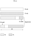
- a structure of a frame is merely an example, and the number of subframes, the number of slots, and the number of symbols in a frame may be variously changed.
- OFDM numerology e.g., SCS
- SCS single-cell resource
- TU Time Unit
- the symbol may include an OFDM symbol (or a CP-OFDM symbol) and an SC-FDMA symbol (or a Discrete Fourier Transform-spread-OFDM, DFT-s-OFDM symbol).
- FIG. 3 illustrates a resource grid of a slot.
- a slot includes a plurality of symbols in a time domain. For example, in the case of a normal CP, one slot includes 14 symbols, but in the case of an extended CP, one slot includes 12 symbols.
- the carrier includes a plurality of subcarriers in a frequency domain.
- a resource block (RB) is defined as a plurality (e.g., 12) of consecutive subcarriers in a frequency domain.
- a bandwidth part (BWP) is defined as a plurality of consecutive physical RBs (PRBs) in a frequency domain, and may correspond to one numerology (e.g., SCS, CP length, etc.).
- a carrier may include a maximum of N (e.g., 5) BWPs. Data communication is performed through an activated BWP, and only one BWP can be activated for one UE.
- Each element in the resource grid is referred to as a resource element (RE), and one complex symbol may
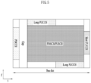
- FIG. 5 illustrates an example in which a physical channel is mapped in a self-contained slot.
- a PDCCH may be transmitted in a DL control region, and a PDSCH may be transmitted in a DL data region.
- a PUCCH may be transmitted in a UL control region, and a PUSCH may be transmitted in a UL data region.
- a GP provides a time gap in the process of a base station and a UE switching from a transmission mode to a reception mode or in the process of switching from a reception mode to a transmission mode. Some symbols of the time of switching from DL to UL in a subframe may be configured to GP.
- a PDCCH carries Downlink Control Information (DCI).
- DCI Downlink Control Information
- DL-SCH downlink shared channel
- UL-SCH uplink shared channel
- PCH paging information for a paging channel
- system information on a DL-SCH resource allocation information for a higher layer control message such as a random access response transmitted on a PDSCH, a transmission power control command, activation/deactivation of Configured Scheduling (CS), etc.
- DL-SCH downlink shared channel
- UL-SCH uplink shared channel
- PCH paging information for a paging channel
- system information on a DL-SCH system information on a DL-SCH
- resource allocation information for a higher layer control message such as a random access response transmitted on a PDSCH, a transmission power control command, activation/deactivation of Configured Scheduling (CS), etc.
- CS Configured Scheduling
- a PDCCH relates to system information (e.g., System Information Block, SIB)
- SIB System Information Block
- a CRC is masked with a System Information RNTI (SI-RNTI).
- SI-RNTI System Information RNTI
- RA-RNTI random access-RNTI
- Table 4 illustrates DCI formats transmitted on a PDCCH.
- DCI format 0_0/0_1 may be referred to as UL grant DCI or UL scheduling information
- DCI format 1_0/1_1 may be referred to as DL grant DCI or UL scheduling information
- DCI format 2_0 is used for transmitting dynamic slot format information (e.g., dynamic SFI) to a UE
- DCI format 2_1 is used for transmitting downlink pre-emption information to a UE.
- DCI format 2_0 and/or DCI format 2_1 may be transmitted to user equipments in a corresponding group through a group common PDCCH, which is a PDCCH transmitted to UEs defined as one group.
- DCI format 0_0 and DCI format 1_0 may be referred to as a fallback DCI format
- DCI format 0_1 and DCI format 1_1 may be referred to as a non-fallback DCI format.
- a fallback DCI format has the same DCI size/field configuration regardless of a UE configuration.
- a non-fallback DCI format has a different DCI size/field configuration according to a UE configuration.
- a PUCCH carries Uplink Control Information (UCI).
- UCI includes:
- Table 5 illustrates PUCCH formats. According to the PUCCH transmission length, it can be divided into Short PUCCH (formats 0, 2) and Long PUCCH (formats 1, 3, 4).
- PUCCH format Length in OFDM symbols N symb PUCCH Number of bits Usage Etc 0 1 - 2 ⁇ 2 HARQ, SR Sequence selection 1 4 - 14 ⁇ 2 HARQ, [SR] Sequence modulation 2 1 - 2 >2 HARQ, CSI, [SR] CP-OFDM 3 4 - 14 >2 HARQ, CSI, [SR] DFT-s-OFDM (no UE multiplexi ng) 4 4 - 14 >2 HARQ, CSI, [SR] DFT-s-OFDM (Pre DFT OCC)
- PUCCH format 1 carries UCI having a maximum size of 2 bits, and a modulation symbol is spread by an orthogonal cover code (OCC) (which is configured differently according to whether or not frequency hopping is performed) in a time domain.
- OCC orthogonal cover code
- a DMRS is transmitted in a symbol in which a modulation symbol is not transmitted (that is, time division multiplexing (TDM) is performed and transmitted).
- PUCCH format 3 UE multiplexing is not performed in the same physical resource blocks, and the PUCCH format 3 carrier UCI having a bit size greater than 2 bits.
- a PUCCH resource of PUCCH format 3 does not include an orthogonal cover code.
- a modulation symbol is transmitted by time division multiplexing (TDM) with a DMRS.
- PUCCH format 4 supports multiplexing up to 4 UEs in the same physical resource blocks, and carries UCI having a bit size greater than 2 bits.
- a PUCCH resource of PUCCH format 3 includes an orthogonal cover code.
- the modulation symbol is transmitted by time division multiplexing (TDM) with a DMRS.
- a UE when transform precoding is not possible (e.g., transform precoding is disabled), a UE transmits a PUSCH based on a CP-OFDM waveform, and when transform precoding is possible (e.g., transform precoding is enabled), a UE transmits a PUSCH based on a CP-OFDM waveform or a DFT-s-OFDM waveform.
- PUSCH transmission may be dynamically scheduled by a UL grant in DCI, or scheduled based on higher layer (e.g., RRC) signaling (and/or Layer 1 (L1) signaling (e.g., PDCCH)) semi-statically (configured grant).
- PUSCH transmission may be performed on a codebook-based transmission or a non-codebook-based transmission.
- FIG. 6 illustrates the ACK / NACK transmission process.
- a UE may detect a PDCCH in slot #n.
- a PDCCH includes downlink scheduling information (e.g., DCI formats 1_0 and 1_1), and the PDCCH indicates a DL assignment-to-PDSCH offset (K0) and a PDSCH-HARQ-ACK reporting offset (K1).
- DCI formats 1_0 and 1_1 may include the following information.
- Table 6 exemplifies a PDSCH-to-HARQ_feedback timing indicator (K1).
- the PDSCH-to-HARQ_feedback timing indicator may be configured with 1 to 3 bits.
- [Table 6] 1 bit 2 bits 3 bits Number of slots k 0 00 000 1st value provided dl-DataToUL-ACK 1 01 001 2nd value provided dl-DataToUL-ACK 10 010 3rd value provided dl-DataToUL-ACK 11 011 4th value provided dl-DataToUL-ACK 100 5th value provided dl-DataToUL-ACK 101 6th value provided dl-DataToUL-ACK 10 7th value provided dl-DataToUL-ACK 11 8th value provided dl-DataToUL-ACK * dl-DataToUL-ACK is a value configured through a higher layer (e.g., RRC) signal.
- RRC Radio Resource Control
- a plurality of parallel DL HARQ processes exist for DL transmission in a base station/UE.
- a plurality of parallel HARQ processes allow DL transmissions to be performed continuously while waiting for HARQ feedback on successful or unsuccessful reception of previous DL transmission.
- Each HARQ process is associated with a HARQ buffer of a MAC (Medium Access Control) layer.
- Each DL HARQ process manages state variables related to the number of transmissions of a MAC PDU (Physical Data Block) in a buffer, HARQ feedback for a MAC PDU in a buffer, and a current redundancy version, etc.
- Each HARQ process is identified by a HARQ process ID.
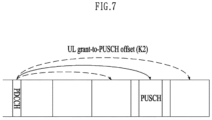
- FIG. 7 illustrates a PUSCH (Physical Uplink Shared Channel) transmission process.
- a UE may detect a PDCCH in a slot #n.
- a PDCCH includes uplink scheduling information (e.g., DCI formats 0_0, 0_1).
- DCI formats 0_0 and 0_1 may include the following information.
- a UE may transmit a PUSCH in a slot #(n+K2) according to scheduling information of a slot #n.
- PUSCH includes UL-SCH TB.
- FIG. 8 illustrates an example of multiplexing UCI to PUSCH.
- UCI may be transmitted through PUSCH as shown (UCI piggyback or PUSCH piggyback).
- FIG. 8 illustrates a case in which HARQ-ACK and CSI are carried on a PUSCH resource.
- FIG. 9 illustrates a wireless communication system supporting an unlicensed band.
- a cell operating in a licensed band hereinafter, L-band
- a carrier of the LCell is defined as a (DL/UL) Licensed Component Carrier (LCC).
- LCC Licensed Component Carrier
- U-band a cell operating in an unlicensed band
- U-band a cell operating in an unlicensed band
- U-band is defined as a UCell
- a carrier of the UCell is defined as an (DL/UL) Unlicensed Component Carrier (UCC).
- a carrier of a cell may mean an operating frequency (e.g., a center frequency) of the cell.
- a cell/carrier e.g., Component Carrier, CC
- FIG. 9(a) illustrates a case in which a UE and a base station transmit and receive signals through an LCC and a UCC (non-standalone (NSA) mode).
- an LCC may be configured to a PCC and a UCC may be configured to a SCC.
- a plurality of LCCs are configured in a UE, one specific LCC may be configured as a PCC and the remaining LCCs may be configured as SCCs.
- FIG. 9(a) corresponds to LAA of a 3GPP LTE system.
- FIG. 9(b) illustrates a case in which a UE and a base station transmit and receive signals through one or more UCCs without any LCC (standalone mode (SA)).
- SA standalone mode
- one of the UCCs may be configured as a PCC and the other UCCs may be configured as SCCs. Accordingly, PUCCH, PUSCH, PRACH transmission, etc. may be supported in a NR UCell. In an unlicensed band of a 3GPP NR system, both an NSA mode and an SA mode may be supported.
- FIG. 10 illustrates a method for occupying a resource in an unlicensed band.
- communication nodes in unlicensed bands should determine whether other communication node(s) use channels before signal transmission. Specifically, a communication node may first perform CS (Carrier Sensing) before transmitting a signal to check whether other communication node(s) are transmitting a signal. A case in which it is determined that other communication node(s) does not transmit a signal is defined as CCA (Clear Channel Assessment) has been confirmed.
- CS Carrier Sensing
- a communication node determines channel state as busy if energy higher than the CCA threshold is detected in a channel, otherwise channel state may be considered as idle.
- a CCA threshold is defined as -62 dBm for a non-Wi-Fi signal and -82 dBm for a Wi-Fi signal. If it is determined that channel state is idle, a communication node may start transmitting a signal in a UCell.
- the above-described series of procedures may be referred to as a Listen-Before-Talk (LBT) or a Channel Access Procedure (CAP).
- LBT Listen-Before-Talk
- CAP Channel Access Procedure
- FBE Framework Based Equipment
- LBE Load Based Equipment
- a channel occupancy time e.g., 1 ⁇ 10ms
- CCA is defined as an operation of observing a channel during a CCA slot (at least 20 ⁇ s) at the end of the idle period.
- a communication node periodically performs CCA in units of fixed frames, and when a channel is unoccupied, it transmits data during a channel occupied time, and when a channel is occupied, it waits until a CCA slot of a next cycle.
- a communication node first configures a value of q ⁇ ⁇ 4, 5, ... , 32 ⁇ , and then performs CCA for one CCA slot.
- data can be transmitted by securing time of maximum (13/32)q ms length.
- a communication node randomly selects a value of N ⁇ 1, 2, ... , q ⁇ and stores it as an initial value of a counter, and then while sensing channel state in units of CCA slots, when a channel is unoccupied in units of CCA slots, the value stored in the counter is decremented by one.
- the counter value becomes 0, a communication node may transmit data by securing a time of maximum (13/32)q ms length.
- a UE may initiate a CAP for signal transmission through an unlicensed band (S1510).
- a UE may arbitrarily select a backoff counter N within a contention window (CW) according to step 1.
- CW contention window
- a value of N is configured to an initial value N init (S1520).
- N init is selected to be any value between 0 and CW p .
- a backoff counter value (N) is 0 (S1530; Y)
- a UE ends a CAP process (S1532).
- a UE may perform Tx burst transmission (S1534).
- a UE decreases a backoff counter value by 1 according to step 2 (S1540). Thereafter, a UE checks whether a channel of a UCell(s) is in an idle state (S1550), and if a channel is in an idle state (S1550; Y), checks whether a backoff counter value is 0 (S1530).
- a UE checks whether a corresponding channel is in an idle state for a delay period (defer duration Td; 25usec or more) longer than a slot time (e.g., 9us) according to step 5 (S1560). If a channel is in an idle state during a delay period (S1570; Y), a UE may resume a CAP process again.
- a delay period may include a 16usec period and m p consecutive slot times (e.g., 9us) immediately following it.
- a UE re-performs step S1560 to check again whether a channel is in an idle state during a new delay period.
- a process in which a base station schedules DL data transmission to a UE through a channel occupancy time (COT) duration secured by performing an LBT (CCA) operation and the base station indicates to transmit HARQ-ACK feedback for the corresponding DL data reception from the corresponding UE through the same COT duration may be considered (hereinafter, an LBT or a CCA is referred to as an LBT for convenience).
- COT channel occupancy time
- CCA LBT
- a process of indicating to transmit HARQ-ACK feedback through another COT duration after the corresponding COT duration may be considered.
- a HARQ-ACK feedback (hereinafter, A/N) configuration/transmission method in a U-band is proposed.
- the A/N configuration/transmission method may be performed in consideration of an LBT operation, a COT configuration, etc.
- the methods proposed in the present disclosure are not limited to the HARQ-ACK feedback transmission method through a PUCCH/PUSCH, and may be similarly applied to other UCI (e.g., CSI, SR) transmission methods through a PUCCH/PUSCH.
- the methods proposed in the present disclosure are not limited to LBT-based U-band operation, and may be similarly applied to L-band (or U-band) operation not accompanied by LBT.
- A/N triggering DCI includes at least DL grant DCI, and (in addition to the DL grant DCI) may further include UL grant DCI and/or specific DCI that does not schedule PDSCH/PUSCH transmission.
- Type-1 A/N codebook For convenience, this A/N feedback configuration/transmission method is referred to as "Type-1 A/N codebook”.
- Each c-DAI/t-DAI may be indicated using a 2-bit value.
- a number greater than 4 can be indicated as follows using a modulo operation.
- a UE may operate to transmit A/N feedback for a slot group (PDSCH reception through the slot group) corresponding to timing-D through the time indicated by timing-A.
- a A/N payload may be mapped (e.g., ordered) in a slot index order belonging to a corresponding slot group.
- a UE may operate to transmit A/N feedback for a slot group (i.e., PDSCH reception through the slot group) corresponding to a slot #(n + K - L) through a slot #(n + K).
- a UE may operate to transmit by combining 1) A/N feedback for a bundling window (PDSCH reception through the bundling window) corresponding to a slot #(n + K) and 2) A/N feedback for a slot group (PDSCH reception through the slot group) corresponding to a slot #(n + K - L), through a slot #(n + K).
- timing-D a specific value (e.g., 0) is configured, it may indicate that there is no corresponding slot group (A/N feedback request for this).
- A/N triggering DCI when A/N triggering DCI is the same as DL grant DCI, it may be indicated through DCI (e.g., through a timing-D indication field) that A/N feedback is transmitted only for a specific part (e.g., first or last slot) among slots belonging to a bundling window (or a slot group corresponding to timing-D) corresponding to timing-A.
- DCI e.g., through a timing-D indication field
- a method of signaling A/N feedback transmission triggering for timing-A/timing-D and a corresponding slot group (e.g., bundling window) corresponding thereto, through UE (group)-common DCI may also be considered.
- a current-ID (c-ID) indicating a slot group ID to which a slot in which a corresponding DCI or a corresponding PDSCH is transmitted belongs may be signaled through DL grant DCI
- a feedback-ID (f-ID) indicating a slot group ID to be an A/N feedback target (DL PDSCH) may be signaled through A/N triggering DCI.
- a UE may transmit A/N feedback for a slot group (PDSCH reception through the slot group) corresponding to a feedback-ID through the time (e.g., slot) indicated as a A/N transmission timing.
- a slot group corresponding to a feedback-ID includes a slot in which a current-ID of the same value as a previous feedback-ID is signaled/received, that is, a slot in which a current-ID having the same value as a feedback-ID is signaled/received through DL grant DCI.
- an A/N payload for a slot group corresponding to a feedback-ID in a situation where a counter-DAI is configured to be signaled through DL grant DCI
- it may be mapped (ordered) in an order of counter-DAI values (e.g., from 1 to N) received through DL grant DCI.
- a counter-DAI may be determined/signaled to have a continuous value (starting from an initial value (e.g., 1)) in one slot group (ID) as shown in FIG. 12(b) . That is, a counter-DAI value may be independently determined/signaled between different slot groups.
- a slot group (indicated through DCI) may be defined in a form of a DAI sequence including counter-DAI values from 1 to N corresponding to the same slot group ID value.
- a slot group may be configured as discontinuous slots based on a received/detected counter-DAI.
- a slot group ID and a DAI sequence ID may be replaced/compatible with each other.
- a UE may operate to transmit (simultaneously, for example, through one PUCCH/PUSCH) by combining (e.g., concatenate) 1) A/N feedback for a bundling window corresponding to timing-A or a slot group (PDSCH reception through the slot group) corresponding to a current-ID and 2) A/N feedback for a slot group (PDSCH reception through the slot group) corresponding to a feedback-ID, through the time indicated by timing-A.
- a feedback-ID is signaled/indicated through A/N triggering DCI (e.g., DL grant DCI, UL grant DCI) may mean that a total-ID indicating the total number of (PDSCH) slot groups (IDs) targeted for A/N feedback transmission/request is signaled through a corresponding DCI, and a specific slot group ID determined from a total-ID and a current-ID is applied as a feedback-ID.
- A/N triggering DCI e.g., DL grant DCI, UL grant DCI
- a feedback-ID may be determined/applied to X (which is the same value as a current-ID).
- a current-ID is indicated as X and a total-ID is indicated as 2
- a feedback- ID may be determined/applied to Y (which is a different value from a current-ID).
- Method 1 This method of determining a feedback-ID is referred to as "Method 1" for convenience.
- a total-DAI and/or a NFI (New Feedback Indicator) for a feedback-ID (corresponding (PDSCH) slot group thereto) signaled/indicated through A/N triggering DCI may means a total-DAI and/or a NFI for a feedback-ID determined according to Method 1, or a total-DAI and/or a NFI for an other-ID (a slot group corresponding thereto) having a value different from a current-ID (regardless of a value indicated as a total-ID).
- a NFI is 1-bit information, for A/N feedback (hereinafter, previous A/N feedback) transmitted at the previous (e.g., recent) time, (a) whether a base station has properly detected/received it, (b) whether a base station has failed to detect/receive it may be signaled.
- a UE may process the remaining parts except for A/N corresponding to a PDSCH scheduled after previous A/N transmission as NACK or DTX (feedback configuration/transmission omitted) to configure/transmit the updated A/N feedback.
- A/N triggering DCI when A/N triggering DCI is the same as DL grant DCI, it may be indicated (through a feedback-ID (or a total-ID) indication field) through DCI that there is no feedback-ID (or other-ID) and/or slot group (A/N feedback request on the slot group) corresponding thereto.
- a feedback-ID when a feedback-ID is indicated with the same value as a current-ID (or a total-ID value is 1), a UE may operate to configure/transmit A/N feedback only for (one) slot group corresponding to the current-ID.
- a current-ID may not be included in UL grant DCI. That is, signaling for a current-ID (and/or a starting-ID) through UL grant DCI may be omitted.
- a UE may operate to configure/transmit A/N feedback (on PUSCH) based on current-ID (and/or starting-ID) information received through DL grant DCI.
- A/N feedback on PUSCH
- it may be indicated through a specific field that there is no A/N feedback transmission request (e.g., a slot group targeted for A/N feedback) through UL grant DCI.
- a specific field may include, for example, a starting-ID and/or a current-ID (and/or a corresponding total-DAI) indication fields.
- a PDSCH scheduling counter value may be determined/indicated in an order of frequency (carrier)-first time (slot)-second in one slot group (ID), or 2) (in a situation in which Opt 1-2 is applied) a PDSCH scheduling counter value may be independently determined/indicated in one slot group (ID) for each carrier.
- A/N feedback is configured/transmitted on a PUCCH/PUSCH based on the Type-2a codebook (and there is no separate NFI information signaling through UL grant DCI).
- (DL grant) DCI scheduling a PDSCH belonging to a specific (PDSCH) slot group (ID) or indicating A/N feedback for a corresponding (PDSCH) slot group may not be detected/received.
- a UE may configure an A/N payload (i.e., 1-bit or more A/N) to piggyback on a PUSCH.
- a UE may configure an A/N payload for ⁇ N + 4M ⁇ (M is an integer greater than or equal to 0) PDSCHs (or N PDSCHs) based on non-toggle NFI assumption (or toggled NFI assumption).
- the proposed operation may be applied to a corresponding (PDSCH) slot group.
- the proposed operation may be applied to a specific (e.g., having the lowest group ID/index) (PDSCH) slot group.
- a UE may assume that an NFI bit value corresponding to a corresponding (PDSCH) slot group (ID) remains the same as the previous (recently) received NFI value (e.g., it is not toggled from the previous (recently) received NFI value), and without considering a corresponding NFI value, a UE may operate to configure or not to configure an A/N payload corresponding to a corresponding (PDSCH) slot group (ID) on a PUSCH based only on a total-DAI value indicated through UL grant DCI.
- the proposed operation may be applied to a corresponding (PDSCH) slot group.
- the proposed operation may be applied to a specific (e.g., having the lowest group ID/index) (PDSCH) slot group.
- a UE may not configure an A/N payload (i.e., 0-bit A/N).
- a total-DAI value N is not 4 (e.g., N ⁇ 4)
- a UE may configure an A/N payload (i.e., 1-bit or more A/N) to piggyback on a PUSCH.
- a UE may configure A/N payloads for N PDSCHs (corresponding to counter-DAI values from 1 to N) to piggyback on a PUSCH.
- the proposed operation may be applied in a state that a PDSCH(s) corresponding to a T-DAI configured in a corresponding (PDSCH) slot group does not belong to any PDSCH group.
- an operation of applying total-DAI, NFI, and/or CTI information may be required.
- the corresponding information may be applied only to, among a plurality of slots or PUSCH resources scheduled through DCI, 1) (a) a PUSCH resource in a first slot (i.e., first-slot PUSCH), (b) a first PUSCH resource (i.e., first PUSCH), (c) an initial PUSCH resource composed of more than a specific number of symbols (or the number of non-DMRS symbols) and/or a specific number of RBs (or the number of REs or the number of non-DMRS REs), (d) a PUSCH resource allocated in a slot immediately following a first slot in which PUSCH transmission is indicated, or (e) a first PUSCH resource (i.e., first full-PUSCH) having the same symbol
- an A/N codebook (payload) may be configured/transmitted based on the most recently detected/received information (e.g., a slot group ID/index, a total-DAI, NFI, a CTI, and/or information indicating whether to fallback A/N, information indicating the presence or absence of pended A/N to be described later) through DL grant DCI, and/or b) b) a specific (e.g., default) value may be assumed/applied for the information.
- the most recently detected/received information e.g., a slot group ID/index, a total-DAI, NFI, a CTI, and/or information indicating whether to fallback A/N, information indicating the presence or absence of pended A/N to be described later
- a specific (e.g., default) value may be assumed/applied for the information.
- DL grant DCI related to the recently detected/received information may be limited to only DCI indicating the PUSCH transmission time (slot) for the HARQ-ACK transmission time for a PDSCH.
- an DL/UL grant DCI information configuration and signaling operation may be limited to a case in which a PUCCH cell/CC (e.g., PCell or PSCell) configured to perform PUCCH transmission in a CA situation is a cell/CC operating on a U-band.
- a PUCCH cell/CC e.g., PCell or PSCell
- DL/UL grant DCI corresponding to all cells/CCs in CA may be configured according to the method proposed in the present disclosure.
- DL/UL grant DCI information configuration and signaling operation as existing one may be applied.
- DL/UL grant DCI corresponding to all aggregated cells/CCs may be configured the same as existing one.
- Type-2a or Type-1 or Type-2 A/N codebook configuration and configuration/signaling of DL/UL grant DCI information according to this may be limited to a case in which a cell/CC operating on a U-band is included in a multi-carrier, that is, a set of a plurality of cells/CCs configured as CA to a UE.
- DL/UL grant DCI corresponding to all aggregated cells/CCs may be configured as in the above-described proposed method.
- the existing Type-1 or Type-2 A/N codebook configuration and configuration/signaling of the existing DL/UL grant DCI information according to this may be applied.
- DL/UL grant DCI corresponding to all aggregated cells/CCs may be configured the same as existing one.
- the above operation may be applied regardless of whether or not NFI toggling corresponding to a PDSCH (or HARQ process ID), or applied only in one case among a case in which corresponding NFI is non-toggled and a case in which corresponding NFI is toggled.
- the feedback update as described above may be omitted (e.g., the previous feedback is maintained).
- a UE may report HARQ-ACK feedback (e.g., updated feedback) with a NACK.
- HARQ-ACK feedback e.g., updated feedback
- a UE may report HARQ-ACK feedback (e.g., updated feedback) with an invalid value (e.g., NACK).
- a method of configuring an A/N payload on a PUCCH may be required.
- a CC index set configured for a UE a HARQ process ID/index set configured for each CC, the (maximum) TB index set or CBG index set configured for each CC, it may need to be determined in which order to map A/N bits corresponding to each ⁇ CC, HARQ ID, TB, or CBG ⁇ combination.
- a UE does not expect DCI (reception) indicating slot Y as A/N transmission timing while scheduling PDSCH transmission (and/or scheduling an initial transmission of a new TB (or indicating a toggled NDI value)), and may operate under the assumption that there is no such DCI. Accordingly, when receiving/receiving the DCI as described above, a UE may ignore the DCI. For example, a UE may not perform an operation indicated by the corresponding DCI.
- a criterion/whether to reset an A/N state may be determined according to whether a UE actually transmits A/N feedback (e.g., ACK).
- A/N feedback e.g., ACK
- the UE may maintain the corresponding A/N state without resetting (e.g., with ACK).
- a method of feeding back an NDI bit (most recently) received through DL grant DCI and an A/N bit for the corresponding PDSCH together for each HARQ process ID may be considered.
- a method of feeding back a calculated bit by performing an XOR (exclusive OR) operation on an NDI bit (most recently) received through DL grant DCI and an A/N bit (e.g., NACK to bit '0', ACK to bit '1') for the corresponding PDSCH for each HARQ process ID may be considered.
- the following A/N feedback method may be considered.
- the Type-1/2/2a codebook-based A/N feedback operation it may be dynamically indicated to transmit the Type-3 codebook-based A/N feedback through DCI.
- a method of indicating a UE to transmit A/N feedback for which CC/HARQ group (among a plurality of predefined/configured CC groups and/or a plurality of HARQ (process ID) groups) may be considered.
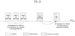
- a UE may configure a final A/N payload in a form that appends or does not append a pended A/N bit(s) (or the corresponding P bits) to a Type-1 A/N codebook.
- a plurality of candidates (having different values including 0) for the appended number of pended A/N bits P may be configured to a UE (through RRC), and a value of one of the candidates may be indicated through a specific field in DCI (e.g., DL grant).
- a terminal may configure a final A/N payload by appending the number of bits corresponding to the indicated value to a Type-1 A/N codebook.
- DCI may include, for example, DCI triggering A/N feedback based on a Type-1 codebook.
- the corresponding pended A/N may be transmitted (by adding) through the earliest among the A/N timings indicated from DCIs (e.g., A/N timing for a PDSCH is indicated as valid or a numeric value) transmitted after the (DCI or PDSCH transmission) time at which A/N pending is indicated (or, the earliest after the minimum PDSCH processing time of a UE from the PDSCH transmission time at which A/N pending is indicated among the indicated A/N timings, or the time indicated as the first A/N timing after the minimum PDSCH processing of a UE from the PDSCH transmission time at which A/N pending is indicated).
- DCI may include, for example, DCI triggering A/N feedback based on a Type-1 codebook.
- the corresponding pended A/N may be transmitted (by adding) through the earliest among the A/N timings indicated from DCI
- a UE may configure a Type-1 A/N codebook for the bundling window in a form of mapping pended A/N information/bit to an A/N bit corresponding to slot X.
- a UE may Opt 1) feedback/transmit a fallback A/N and the corresponding pended A/N together through the A/N timing, or Opt 2) operate to feedback/transmit only fallback A/N (same as before) through the A/N timing (therefore, in this case, as an exception, it operates not to add/feedback the pended A/N through a A/N timing indicated for fallback A/N transmission), or Opt 3) feedback/transmit by adding the corresponding pended A/N to the entire Type-1 codebook through the A/N timing (therefore, in this case, fallback A/N transmission is performed only through A/N timing that is not determined as the pended A/N feedback/transmission time).
- a Type-2 A/N codebook method in case of a PDSCH in which A/N pending is indicated through specific DL grant DCI (e.g., in a form in which an A/N timing for a PDSCH is indicated as invalid or non-numeric value), for (pended) A/N feedback for the corresponding PDSCH, 1) an operation of transmitting (by a UE) the corresponding pended A/N in a form of a Type-3 A/N codebook by indicating a separate A/N pooling through specific DCI, or 2) an operation of appending the corresponding pended A/N to a Type-2 A/N codebook transmitted through an A/N timing indicated (e.g., indicated in a form in which an A/N timing for a PDSCH is indicated as valid or a numeric value) by another DL grant DCI without a separate A/N pooling may be considered.
- DCI e.g., in a form in which an A/N timing for a PDSCH
- a UE may configure a final A/N payload in a form of appending the pended A/N bit(s) (payload) (to a Type-2 A/N codebook) configured/mapped based on the corresponding total value and/or according to an order of the corresponding order value.
- a final A/N payload may be configured in a form in which a Type-2 A/N codebook is preferentially mapped to a lower bit index part starting with a MSB (e.g., configured as a form of a first A/N sub-codebook), and then pended A/N information is mapped (to a higher bit index part) after it (e.g., configured as a form of a second A/N sub-codebook).
- an A/N feedback transmission time for a PDSCH for which A/N pending is indicated may be determined as the earliest A/N PUCCH (or PUSCH) transmission (the corresponding transmission is configured/indicated/performed) (after the minimum PDSCH processing time of a UE) from the corresponding PDSCH reception time.
- an A/N PUCCH is an A/N feedback-dedicated PUCCH resource corresponding to a SPS PDSCH
- a PUCCH resource indicated by a PRI included in DCI indicating A/N pending an A/N for a PDSCH in which A/N pending is indicated and an A/N for a SPS PDSCH may be fed back/transmitted together.
- an A/N PUCCH is an A/N dedicated PUCCH resource corresponding to a SPS PDSCH in a state in which a Type-2 A/N codebook method is configured for a UE
- 1) an A/N corresponding to a PDSCH (including a PDSCH for which A/N pending is not indicated) from an initial counter-DAI value to a total-DAI (or counter-DAI) value included in DCI indicating A/N pending and an A/N for a SPS PDSCH may be configured/transmitted on the same single PUCCH (or PUSCH), or 2) (except for a PDSCH where A/N pending is not indicated) an A/N for a PDSCH for which A/N pending is indicated and an A/N for a SPS PDSCH may be configured/transmitted together on the same single PUCCH (or PUSCH).
- a retransmission request (e.g., according to LBT failure of a UE and/or A/N detection failure of a base station) for A/N feedback corresponding to an SPS PDSCH is not possible because there is no separate slot group ID designation for an SPS PDSCH, 1) A/N feedback transmission time for an SPS PDSCH, and 2) A/N feedback configuration/mapping rule on a Type-2a A/N codebook may be required.
- an SPS PDSCH period is configured with L slots and an A/N timing (delay) corresponding to an SPS PDSCH is indicated with K slots.
- A/N feedback for an SPS PDSCH transmitted in slot #n may be transmitted (repeatedly) through all A/N timings indicated in an interval from slot #(n+K) to slot #(n+K+L-1).
- an A/N configuration/mapping for an SPS PDSCH on a Type-2a A/N codebook may be configured/mapped by separating from an A/N for PDSCHs to which a slot group ID is assigned through DCI (e.g., DL grant).
- DCI e.g., DL grant
- an A/N for a PDSCH for which a slot group ID is designated may be mapped to a lower bit index part starting with a MSB (e.g., configured as a form of a first A/N sub-codebook), and then an A/N for an SPS PDSCH is mapped (to a higher bit index part) after it (e.g., configured as a form of a second A/N sub-codebook).
- a MSB e.g., configured as a form of a first A/N sub-codebook
- an A/N for an SPS PDSCH is mapped (to a higher bit index part) after it (e.g., configured as a form of a second A/N sub-codebook).
- an A/N configuration/mapping for an SPS PDSCH on a Type-3 A/N codebook may be configured/mapped separately from an A/N for PDSCHs for which a HARQ process ID is designated through DCI (e.g., DL grant).
- DCI e.g., DL grant
- an A/N for a PDSCH for which a HARQ process ID may designated through DCI is mapped to a lower bit index part starting with a most significant bit (MSB) (e.g., configured as a form of a first A/N sub-codebook), and then an A/N for an SPS PDSCH is mapped (to a higher bit index part) after it (e.g., configured as a form of a second A/N sub-codebook).
- MSB most significant bit
- an A/N payload may be configured in a form in which an A/N corresponding to each HARQ process ID is mapped.
- a PDCCH indicating release for a SPS PDSCH may indicate that the PDCCH is for releasing a SPS by using a HARQ process ID field in DCI.
- an entire Type-3 A/N codebook may be configured in a form of adding (1-bit) A/N information for a SPS release PDCCH to a specific location of an A/N payload in the state that an A/N payload is configured by mapping an A/N by each HARQ process ID.
- a PUCCH resource for A/N feedback transmission corresponding to an initial PDSCH reception may be 1) directly indicated through SPS activation DCI, 2) determined as a specific (e.g., corresponding to the minimum or maximum index) resource among a plurality of candidate PUCCH resource indexes (PRI) configured through RRC, or 3) predefined as a specific resource or configured through RRC.
- a specific applicable value applied to an A/N transmission timing for an initial PDSCH reception may be 1) predefined as a specific value or configured through RRC, 2) determined as a specific (e.g., minimum or maximum) value among a plurality of candidate (applicable) K1 values configured through RRC, or 3) directly indicated through SPS activation DCI.
- an operation in which a non-applicable value is indicated as an A/N timing through DCI indicating SPS activation may be allowed only when a Type-2a (and/or Type-3) A/N codebook or a Type-2 (and/or Type-3) A/N codebook is configured for a UE, and the corresponding operation may not be allowed when a Type-1 (and/or Type-3) A/N codebook is configured for a UE.
- A/N feedback request for a plurality of SPS PDSCHs in which A/N pending is indicated can be requested through any DCI indicating A/N transmission based on a Type-2a and/or Type-3 codebook when a Type-2a A/N codebook is configured for a UE, and can be requested through any DCI indicating A/N transmission based on a Type-2 and/or Type-3 codebook when a Type-2 A/N codebook is configured for a UE, and can be request only through DCI indicating A/N transmission based on a Type-3 codebook (with a small request opportunity and limitedly) when a Type-1 A/N codebook is configured for a UE.
- an A/N timing corresponding to the corresponding DCI reception may be defined so that it is not indicated as an unapplicable value (or so that it is indicated only as an applicable value).
- FIG. 17 illustrates an A/N process according to the present disclosure.
- a UE may receive DCI (e.g., DL grant DCI; DCI format 1_X) including an A/N timing indicator (refer to Table 6) (S1802).
- DCI may be accompanied by PDSCH scheduling or may request A/N feedback without PDSCH scheduling.
- an A/N timing indicator indicates an applicable value (S1804; No)
- a UE may perform A/N transmission in a slot determined based on a value indicated by an A/N timing indicator (S1806).
- a method of analyzing/applying a state to which an inapplicable value is mapped among states indicated by an A/N timing field in DCI is substituted/changed with a specific applicable value for special DCI is also possible.
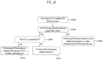
- FIG. 18 illustrates an A/N process according to the present disclosure.
- a UE may receive DCI (e.g., DL grant DCI; DCI format 1_X) including an A/N timing indicator (refer to Table 6) (S1902).
- DCI may be accompanied by PDSCH scheduling or may request A/N feedback without PDSCH scheduling.
- an A/N timing indicator indicates an applicable value (S1904; No)
- a UE may perform A/N transmission in a slot determined based on a value indicated by an A/N timing indicator (S1906).
- Case 2 As DL grant DCI indicating A/N feedback transmission based on a Type-3 codebook, two methods of Case 1) DCI including PDSCH scheduling, or Case 2) DCI without PDSCH scheduling may be considered. In Case 2, if a PDSCH frequency resource allocated by the corresponding DCI is invalid (e.g., empty), a UE may operate by recognizing that a Type-3 A/N codebook is indicated without PDSCH scheduling.
- the NR system defines a minimum processing time (e.g., N2) in relation to PUSCH transmission of a UE.
- N2 a minimum processing time
- a UE transmits a PUSCH carrying a TB scheduled by the UL grant PDCCH.
- the corresponding interval is less than N2 symbols, a UE may ignore a UL grant PDCCH and drop a corresponding PUSCH transmission.
- N2 may have different values according to SCS applied to UL grant PDCCH and PUSCH transmission.
- Table 9 represents a minimum PUSCH processing time (N2) according to a SCS value. [Table 9] SCS (kHz) 15 10 30 12 60 23 120 36
- a DL grant PDCCH indicates only (Type-3 codebook-based) A/N feedback transmission without PDSCH scheduling
- Nx the corresponding number of symbols
- a UE may feed back valid (Type-3 codebook-based) A/N information corresponding to a corresponding PDCCH.
- the corresponding interval is less than Nx symbols, a UE may 1) not feed back valid A/N information, or 2) ignore a corresponding PDCCH itself.
- N1 values (or, (N1+a) value obtained by adding a specific number a of symbols to N1, where a may be configured to a positive or negative number) applied when an additional DMRS symbol (group) is not configured among the values shown in Table 8 may be applied as the Nx value.
- N1 values or, (N1+a) value obtained by adding a specific number a of symbols to N1, where a may be configured to a positive or negative number
- an additional DMRS symbol (group) may be applied as the Nx value.
- the following DL DCI signaling method may be considered for configuring a Type-2 A/N codebook.
- DCI-X T-DAI information through DL DCI
- DCI-X one of the following two methods may be configured for a UE through RRC signaling.
- the following UL DCI signaling method may be considered for configuring a Type-2 A/N codebook.
- DCI-Y UL DCI
- a communication system 1 applied to the present disclosure includes a wireless device, a base station, and a network.
- the wireless device means a device that performs communication using a wireless access technology (e.g., 5G NR (New RAT), LTE (Long Term Evolution)), and may be referred to as a communication/wireless/5G device.
- the wireless device may include robots 100a, vehicles 100b-1 and 100b-2, an extended reality (XR) device 100c, a hand-held device 100d, and a home appliance 100e.
- XR extended reality
- a hand-held device 100d a hand-held device 100d
- a home appliance 100e e.
- IoT Internet of Thing
- AI device / server 400 an AI device / server 400.
- the vehicle may include a vehicle equipped with a wireless communication function, an autonomous driving vehicle, a vehicle capable of performing inter-vehicle communication, and the like.
- the vehicle may include an Unmanned Aerial Vehicle (UAV) (e.g., a drone).
- UAV Unmanned Aerial Vehicle
- the XR device includes AR (Augmented Reality) / VR (Virtual Reality) / MR (Mixed Reality) devices, and it may be implemented in the form of a HMD (Head-Mounted Device), a HUD (Head-Up Display) in a vehicle, a TV, a smartphone, a computer, a wearable device, a home appliance, a digital signage, a vehicle, a robot, and the like.
- HMD Head-Mounted Device
- HUD Head-Up Display
- FIG. 19 illustrates a communication system 1 to which the present disclosure is applied.
- a communication system 1 applied to the present disclosure includes a wireless device, a base station, and a network.
- the wireless device means a device that performs communication using a wireless access technology (e.g., 5G NR (New RAT), LTE (Long Term Evolution)), and may be referred to as a communication/wireless/5G device.
- the wireless device may include robots 100a, vehicles 100b-1 and 100b-2, an extended reality (XR) device 100c, a hand-held device 100d, and a home appliance 100e.
- XR extended reality
- a hand-held device 100d a hand-held device 100d
- a home appliance 100e e.
- IoT Internet of Thing
- AI device / server 400 an AI device / server 400.
- the vehicle may include a vehicle equipped with a wireless communication function, an autonomous driving vehicle, a vehicle capable of performing inter-vehicle communication, and the like.
- the vehicle may include an Unmanned Aerial Vehicle (UAV) (e.g., a drone).
- UAV Unmanned Aerial Vehicle
- the XR device includes AR (Augmented Reality) / VR (Virtual Reality) / MR (Mixed Reality) devices, and it may be implemented in the form of a HMD (Head-Mounted Device), a HUD (Head-Up Display) in a vehicle, a TV, a smartphone, a computer, a wearable device, a home appliance, a digital signage, a vehicle, a robot, and the like.
- HMD Head-Mounted Device
- HUD Head-Up Display
- the hand-held device may include a smart phone, a smart pad, a wearable device (e.g., a smart watch, a smart glass), a computer (e.g., a notebook computer, etc.).
- the home appliance may include a TV, a refrigerator, a washing machine, and the like.
- the IoT device may include a sensor, a smart meter, and the like.
- the base station and the network may be implemented as a wireless device, and the specific wireless device 200a may operate as a base station/network node to other wireless devices.
- the wireless devices 100a to 100f may be connected to the network 300 through the base station 200.
- AI Artificial Intelligence
- the network 300 may be configured using a 3G network, a 4G (e.g., LTE) network, or a 5G (eg, NR) network, and the like.
- the wireless devices 100a to 100f may communicate with each other through the base station 200/network 300, but may communicate directly (e.g. sidelink communication) without passing through the base station/network.
- the vehicles 100b-1 and 100b-2 may perform direct communication (e.g.
- V2V Vehicle to Vehicle
- V2X Vehicle to everything
- the IoT device e.g., sensor
- the IoT device may directly communicate with other IoT devices (e.g., sensors) or other wireless devices 100a to 100f.
- Wireless communication/connections 150a, 150b, and 150c may be established between the wireless devices 100a to 100f/base station 200 and the base station 200/base station 200.
- wireless communication/connection may be achieved through various wireless access technologies (e.g. 5G NR) such as uplink/downlink communication 150a, sidelink communication 150b (or D2D communication), base station communication 150c (e.g., relay, Integrated Access Backhaul (IAB)).
- 5G NR wireless access technologies
- IAB Integrated Access Backhaul
- the wireless device and the base station/wireless device, and the base station and the base station can transmit/receive radio signals to each other.
- the wireless communication/connection 150a, 150b, 150c may transmit/receive signals through various physical channels.
- a first wireless device 100 may include one or more processors 102 and one or more memories 104 and may additionally include one or more transceivers 106 and/or one or more antennas 108.
- a processor 102 may control a memory 104 and/or a transceiver 106 and may be configured to implement description, functions, procedures, proposals, methods and/or operation flow charts included in the present disclosure.
- a processor 102 may transmit a wireless signal including first information/signal through a transceiver 106 after generating first information/signal by processing information in a memory 104.
- a processor 102 may receive a wireless signal including second information/signal through a transceiver 106 and then store information obtained by signal processing of second information/signal in a memory 104.
- a second wireless device 200 may include one or more processors 202 and one or more memories 204 and may additionally include one or more transceivers 206 and/or one or more antennas 208.
- a processor 202 may control a memory 204 and/or a transceiver 206 and may be configured to implement description, functions, procedures, proposals, methods and/or operation flows charts included in the present disclosure.
- a processor 202 may generate third information/signal by processing information in a memory 204, and then transmit a wireless signal including third information/signal through a transceiver 206.
- a processor 202 may receive a wireless signal including fourth information/signal through a transceiver 206, and then store information obtained by signal processing of fourth information/signal in a memory 204.
- a memory 204 may be connected to a processor 202 and may store a variety of information related to an operation of a processor 202.
- a memory 204 may store a software code including commands for performing all or part of processes controlled by a processor 202 or for performing description, functions, procedures, proposals, methods and/or operation flow charts included in the present disclosure.
- a processor 202 and a memory 204 may be part of a communication modem/circuit/chip designed to implement a wireless communication technology (e.g., LTE, NR).
- One or more processors 102, 202 may receive a signal (e.g., a baseband signal) from one or more transceivers 106, 206 and obtain a PDU, a SDU, a message, control information, data or information according to description, functions, procedures, proposals, methods and/or operation flow charts included in the present disclosure.
- a signal e.g., a baseband signal
- One or more processors 102, 202 may be referred to as a controller, a micro controller, a micro processor or a micro computer.
- One or more processors 102, 202 may be implemented by a hardware, a firmware, a software, or their combination.
- one or more ASICs Application Specific Integrated Circuit
- one or more DSPs Digital Signal Processor
- one or more DSPDs Digital Signal Processing Device
- one or more PLDs Programmable Logic Device
- FPGAs Field Programmable Gate Arrays
- One or more transceivers 106, 206 may transmit user data, control information, a wireless signal/channel, etc. mentioned in methods and/or operation flow charts, etc. of the present disclosure to one or more other devices.
- One or more transceivers 106, 206 may receiver user data, control information, a wireless signal/channel, etc. mentioned in description, functions, procedures, proposals, methods and/or operation flow charts, etc. included in the present disclosure from one or more other devices.
- one or more transceivers 106, 206 may be connected to one or more processors 102, 202 and may transmit and receive a wireless signal.
- one or more processors 102, 202 may control one or more transceivers 106, 206 to transmit user data, control information or a wireless signal to one or more other devices.
- one or more processors 102, 202 may control one or more transceivers 106, 206 to receive user data, control information or a wireless signal from one or more other devices.
- one or more transceivers 106, 206 may be connected to one or more antennas 108, 208 and one or more transceivers 106, 206 may be configured to transmit and receive user data, control information, a wireless signal/channel, etc. mentioned in description, functions, procedures, proposals, methods and/or operation flow charts, etc.
- the wireless devices 100 and 200 correspond to the wireless devices 100 and 200 of FIG. 20 , and may be composed of various elements, components, units and/or modules.
- the wireless devices 100 and 200 may include a communication unit 110, a control unit 120, a memory unit 130, and additional components 140.
- the communication unit may include a communication circuit 112 and a transceiver(s) 114.
- the communication circuit 112 may include one or more processors 102 and 202 and/or one or more memories 104 and 204 of Fig. 20 .
- the transceiver(s) 114 may include one or more transceivers 106, 206 and/or one or more antennas 108, 208 of FIG. 20 .
- the wireless device may be used in a mobile or fixed place depending on the use-example/service.
- various elements, components, units, and/or modules in the wireless devices 100 and 200 may be entirely interconnected through a wired interface, or at least some may be wirelessly connected through the communication unit 110.
- the control unit 120 and the communication unit 110 may be connected by wire, and the control unit 120 and the first unit (e.g., 130, 140) may be connected wirelessly through the communication unit 110.
- each element, component, unit, and/or module in the wireless device 100 and 200 may further include one or more elements.
- the control unit 120 may be composed of one or more processor sets.
- control unit 120 may be composed of a set of a communication control processor, an application processor, an electronic control unit (ECU), a graphic processing processor, and a memory control processor.
- memory unit 130 may be composed of a random access memory (RAM), a dynamic RAM (DRAM), a read only memory (ROM), a flash memory, a volatile memory, and a non-volatile memory and/or a combination thereof.
- FIG. 22 illustrates a vehicle or an autonomous driving vehicle to which the present disclosure is applied.
- the vehicle or the autonomous driving vehicle may be implemented as a mobile robot, a vehicle, a train, an aerial vehicle (AV), a ship, and the like.
- AV aerial vehicle
- the vehicle or the autonomous driving vehicle 100 may include an antenna unit 108, a communication unit 110, a control unit 120, a driving unit 140a, a power supply unit 140b, a sensor unit 140c and an autonomous driving unit 140d.
- the antenna unit 108 may be configured as a part of the communication unit 110.
- Blocks 110/130/140a-140d correspond to blocks 110/130/140 of FIG. 21 , respectively.
- the communication unit 110 may transmit and receive signals (e.g., data, control signals, etc.) with external devices such as other vehicles, base stations (e.g., base stations, roadside units, etc.), servers, and the like.
- the control unit 120 may perform various operations by controlling elements of the vehicle or the autonomous driving vehicle 100.
- the control unit 120 may include an Electronic Control Unit (ECU).
- the driving unit 140a may cause the vehicle or the autonomous driving vehicle 100 to run on the ground.
- the driving unit 140a may include an engine, a motor, a power train, a wheel, a brake, a steering device, and the like.
- the power supply unit 140b supplies power to the vehicle or the autonomous driving vehicle 100, and may include a wired/wireless charging circuit, a battery, and the like.
- the sensor unit 140c may obtain vehicle status, surrounding environment information, user information, and the like.
- the sensor unit 140c may include an inertial measurement unit (IMU) sensor, a collision sensor, a wheel sensor, a speed sensor, an inclination sensor, a weight sensor, a heading sensor, a position module, a vehicle forward/reverse sensor, a battery sensor, a fuel sensor, a tire sensor, a steering sensor, a temperature sensor, a humidity sensor, an ultrasonic sensor, an illuminance sensor, a pedal position sensor, and the like.
- IMU inertial measurement unit
- the autonomous driving unit 140d may implement a technology for maintaining a driving lane, a technology for automatically adjusting speed such as adaptive cruise control, a technology for automatically driving along a predetermined route, a technology for automatically setting a route when a destination is set, etc.
- the communication unit 110 may receive map data, traffic information data, and the like from an external server.
- the autonomous driving unit 140d may generate an autonomous driving route and a driving plan based on the acquired data.
- the control unit 120 may control the driving unit 140a to move the vehicle or the autonomous driving vehicle 100 along the autonomous driving path (e.g., speed/direction adjustment) according to the driving plan.
- the communication unit 110 may obtain the latest traffic information data from an external server aperiodically/periodically, and may acquire surrounding traffic information data from surrounding vehicles.
- the sensor unit 140c may acquire vehicle state and surrounding environment information.
- the autonomous driving unit 140d may update the autonomous driving route and driving plan based on the newly acquired data/information.
- the communication unit 110 may transmit information about a vehicle location, an autonomous driving route, a driving plan, and the like to an external server.
- the external server may predict traffic information data in advance using AI technology or the like based on information collected from the vehicle or the autonomous driving vehicles, and may provide the predicted traffic information data to the vehicle or autonomous driving vehicles.
- the present disclosure can be used in a terminal, a base station, or other equipment of a wireless mobile communication system.
Landscapes
- Engineering & Computer Science (AREA)
- Signal Processing (AREA)
- Computer Networks & Wireless Communication (AREA)
- Mobile Radio Communication Systems (AREA)
Claims (12)
- Verfahren zum Senden von Steuerinformationen durch eine Benutzerausrüstung, UE (100), in einem Drahtloskommunikationssystem, wobei das Verfahren umfasst:Empfangen von ersten Downlink-Steuerinformationen, DCI, zum Planen von mindestens einem gemeinsam genutzten physikalischen Downlink-Kanal, PDSCH, wobei die ersten DCI einen ersten PDSCH-Gruppenindex einer PDSCH-Gruppe von zwei PDSCH-Gruppen, wobei eine PDSCH-Gruppe eine PDSCH-Schlitzgruppe ist, und einen Wert einer Gesamtanzahl von PDSCH-Gruppen, für die Bestätigungs-/Negativbestätigungs-, A/N, Rückmeldung erforderlich ist, beinhalten, und wobei ein zweiter PDSCH-Gruppenindex der anderen der zwei PDSCH-Gruppen auf Basis des ersten PDSCH-Gruppenindex bestimmt wird;Empfangen des mindestens einen PDSCH, wobei jeder PDSCH zu einer der zwei PDSCH-Gruppen gehört;Empfangen von zweiten DCI zum Planen eines gemeinsam genutzten physikalischen Uplink-Kanals, PUSCH, wobei die zweiten DCI einen einzigen Downlink-Zuweisungsindex, DAI, beinhalten, der sich auf nur eine der zwei PDSCH-Gruppen bezieht; undSenden der Steuerinformationen im PUSCH, wobei die Steuerinformationen mindestens eines beinhalten von:- einem ersten A/N-Codebuch für eine der zwei PDSCH-Gruppen mit dem ersten und dem zweiten PDSCH-Gruppenindex, und- einem zweiten A/N-Codebuch für die andere der zwei PDSCH-Gruppen mit dem ersten und dem zweiten PDSCH-Gruppenindex,wobei in einem Fall, in dem die Steuerinformationen eines des ersten und des zweiten A/N-Codebuches beinhalten, das sich auf eine PDSCH-Gruppe mit dem ersten PDSCH-Gruppenindex in den ersten DCI bezieht, der DAI verwendet wird, um das eine des ersten und des zweiten A/N-Codebuches in den Steuerinformationen zu erzeugen, undwobei in einem Fall, in dem die Steuerinformationen sowohl das erste als auch das zweite A/N-Codebuch beinhalten und die ersten DCI einen niedrigsten Wert als ersten PDSCH-Gruppenindex angeben, der DAI verwendet wird, um ein A/N-Codebuch für eine der zwei PDSCH-Gruppen mit dem ersten PDSCH-Gruppenindex zu erzeugen.
- Verfahren nach Anspruch 1, wobei auf Basis dessen, dass durch den Wert einer Gesamtanzahl von PDSCH-Gruppen in den ersten DCI A/N-Rückmeldung für nur eine PDSCH-Gruppe unter den zwei PDSCH-Gruppen gefordert wird, die Steuerinformationen nur ein A/N-Codebuch beinhalten, das sich auf eine PDSCH-Gruppe mit dem ersten PDSCH-Gruppenindex in den ersten DCI bezieht.
- Verfahren nach Anspruch 1, wobei auf Basis dessen, dass durch den Wert einer Gesamtanzahl von PDSCH-Gruppen in den ersten DCI A/N-Rückmeldung für die zwei PDSCH-Gruppen gefordert wird, die Steuerinformationen sowohl das erste als auch das zweite A/N-Codebuch beinhalten.
- Verfahren nach Anspruch 1, wobei auf Basis dessen, dass die Steuerinformationen sowohl das erste als auch das zweite A/N-Codebuch beinhalten, eine Größe eines A/N-Codebuches für eine verbleibende PDSCH-Gruppe unter den zwei PDSCH-Gruppen auf Basis eines Gesamt-DAI bestimmt wird, der zum Planen eines PDSCH einer entsprechenden PDSCH-Gruppe verwendet wird.
- Verfahren nach Anspruch 1, wobei die Steuerinformationen in einem nicht lizenzierten Band gesendet werden.
- Vorrichtung für eine Benutzerausrüstung, UE (100), wobei die Vorrichtung umfasst:mindestens einen Prozessor (102); undmindestens einen Computerspeicher (104), der mit dem mindestens einen Prozessor (102) wirkverbunden ist und, wenn er ausgeführt wird, den mindestens einen Prozessor (102) dazu bringt, eine Operation durchzuführen, wobei die Operation umfasst:Empfangen von ersten Downlink-Steuerinformationen, DCI, zum Planen von mindestens einem gemeinsam genutzten physikalischen Downlink-Kanal, PDSCH, wobei die ersten DCI einen ersten PDSCH-Gruppenindex einer PDSCH-Gruppe von zwei PDSCH-Gruppen, wobei eine PDSCH-Gruppe eine PDSCH-Schlitzgruppe ist, und einen Wert einer Gesamtanzahl von PDSCH-Gruppen, für die Bestätigungs-/Negativbestätigungs-, A/N, Rückmeldung erforderlich ist, beinhalten, und wobei ein zweiter PDSCH-Gruppenindex der anderen der zwei PDSCH-Gruppen auf Basis des ersten PDSCH-Gruppenindex bestimmt wird;Empfangen des mindestens einen PDSCH, wobei jeder PDSCH zu einer der zwei PDSCH-Gruppen gehört;Empfangen von zweiten DCI zum Planen eines gemeinsam genutzten physikalischen Uplink-Kanals, PUSCH, wobei die zweiten DCI einen einzigen Downlink-Zuweisungsindex, DAI, beinhalten, der sich auf nur eine der zwei PDSCH-Gruppen bezieht; undSenden der Steuerinformationen im PUSCH, wobei die Steuerinformationen mindestens eines beinhalten von:- einem ersten A/N-Codebuch für eine der zwei PDSCH-Gruppen mit dem ersten und dem zweiten PDSCH-Gruppenindex, und- einem zweiten A/N-Codebuch für die andere der zwei PDSCH-Gruppen mit dem ersten und dem zweiten PDSCH-Gruppenindex,wobei in einem Fall, in dem die Steuerinformationen eines des ersten und des zweiten A/N-Codebuches beinhalten, das sich auf eine PDSCH-Gruppe mit dem ersten PDSCH-Gruppenindex in den ersten DCI bezieht, der DAI verwendet wird, um das eine des ersten und des zweiten A/N-Codebuches in den Steuerinformationen zu erzeugen, undwobei in einem Fall, in dem die Steuerinformationen sowohl das erste als auch das zweite A/N-Codebuch beinhalten und die ersten DCI einen niedrigsten Wert als ersten PDSCH-Gruppenindex angeben, der DAI verwendet wird, um ein A/N-Codebuch für eine der zwei PDSCH-Gruppen mit dem ersten PDSCH-Gruppenindex zu erzeugen.
- Vorrichtung nach Anspruch 6, wobei auf Basis dessen, dass durch den Wert einer Gesamtanzahl von PDSCH-Gruppen in den ersten DCI A/N-Rückmeldung für nur eine PDSCH-Gruppe unter den zwei PDSCH-Gruppen gefordert wird, die Steuerinformationen nur ein A/N-Codebuch beinhalten, das sich auf eine PDSCH-Gruppe mit dem ersten PDSCH-Gruppenindex in den ersten DCI bezieht.
- Vorrichtung nach Anspruch 6, wobei auf Basis dessen, dass durch den Wert einer Gesamtanzahl von PDSCH-Gruppen in den ersten DCI A/N-Rückmeldung für die zwei PDSCH-Gruppen gefordert wird, die Steuerinformationen sowohl das erste als auch das zweite A/N-Codebuch beinhalten.
- Vorrichtung nach Anspruch 6, wobei auf Basis dessen, dass die Steuerinformationen sowohl das erste als auch das zweite A/N-Codebuch beinhalten, eine Größe eines A/N-Codebuches für eine verbleibende PDSCH-Gruppe unter den zwei PDSCH-Gruppen auf Basis eines Gesamt-DAI bestimmt wird, der zum Planen eines PDSCH einer entsprechenden PDSCH-Gruppe verwendet wird.
- Vorrichtung nach Anspruch 6, wobei die Steuerinformationen in einem nicht lizenzierten Band gesendet werden.
- Benutzerausrüstung, UE (100), die die Vorrichtung nach einem der Ansprüche 6 bis 10 beinhaltet.
- Verfahren zum Empfangen von Steuerinformationen durch eine Basisstation (200) in einem Drahtloskommunikationssystem, wobei das Verfahren umfasst:Senden von ersten Downlink-Steuerinformationen, DCI, zum Planen von mindestens einem gemeinsam genutzten physikalischen Downlink-Kanal, PDSCH, wobei die ersten DCI einen ersten PDSCH-Gruppenindex einer PDSCH-Gruppe von zwei PDSCH-Gruppen, wobei eine PDSCH-Gruppe eine PDSCH-Schlitzgruppe ist, und einen Wert einer Gesamtanzahl von PDSCH-Gruppen, für die Bestätigungs-/Negativbestätigungs-, A/N, Rückmeldung erforderlich ist, beinhalten, und wobei ein zweiter PDSCH-Gruppenindex der anderen der zwei PDSCH-Gruppen auf Basis des ersten PDSCH-Gruppenindex bestimmt wird;Senden des mindestens einen PDSCH, wobei jeder PDSCH zu einer der zwei PDSCH-Gruppen gehört;Senden von zweiten DCI zum Planen eines gemeinsam genutzten physikalischen Uplink-Kanals, PUSCH, wobei die zweiten DCI einen einzigen Downlink-Zuweisungsindex, DAI, beinhalten, der sich auf nur eine der zwei PDSCH-Gruppen bezieht; undEmpfangen der Steuerinformationen im PUSCH, wobei die Steuerinformationen mindestens eines beinhalten von:- einem ersten A/N-Codebuch für eine der zwei PDSCH-Gruppen mit dem ersten und dem zweiten PDSCH-Gruppenindex, und- einem zweiten A/N-Codebuch für die andere der zwei PDSCH-Gruppen mit dem ersten und dem zweiten PDSCH-Gruppenindex,wobei in einem Fall, in dem die Steuerinformationen eines des ersten und des zweiten A/N-Codebuches beinhalten, das sich auf eine PDSCH-Gruppe mit dem ersten PDSCH-Gruppenindex in den ersten DCI bezieht, der DAI verwendet wird, um das eine des ersten und des zweiten A/N-Codebuches in den Steuerinformationen zu erzeugen, undwobei in einem Fall, in dem die Steuerinformationen sowohl das erste als auch das zweite A/N-Codebuch beinhalten und die ersten DCI einen niedrigsten Wert als ersten PDSCH-Gruppenindex angeben, der DAI verwendet wird, um ein A/N-Codebuch für eine der zwei PDSCH-Gruppen mit dem ersten PDSCH-Gruppenindex zu erzeugen.
Applications Claiming Priority (11)
| Application Number | Priority Date | Filing Date | Title |
|---|---|---|---|
| US201962931743P | 2019-11-06 | 2019-11-06 | |
| US201962932537P | 2019-11-08 | 2019-11-08 | |
| US201962936580P | 2019-11-17 | 2019-11-17 | |
| US201962938280P | 2019-11-20 | 2019-11-20 | |
| KR20200017987 | 2020-02-13 | ||
| US202062983554P | 2020-02-28 | 2020-02-28 | |
| US202063006704P | 2020-04-07 | 2020-04-07 | |
| US202063007292P | 2020-04-08 | 2020-04-08 | |
| US202063012248P | 2020-04-19 | 2020-04-19 | |
| KR20200062631 | 2020-05-25 | ||
| PCT/KR2020/015489 WO2021091292A1 (ko) | 2019-11-06 | 2020-11-06 | 무선 통신 시스템에서 무선 신호 송수신 방법 및 장치 |
Publications (3)
| Publication Number | Publication Date |
|---|---|
| EP4057536A1 EP4057536A1 (de) | 2022-09-14 |
| EP4057536A4 EP4057536A4 (de) | 2023-01-11 |
| EP4057536B1 true EP4057536B1 (de) | 2025-04-09 |
Family
ID=75848918
Family Applications (1)
| Application Number | Title | Priority Date | Filing Date |
|---|---|---|---|
| EP20884146.0A Active EP4057536B1 (de) | 2019-11-06 | 2020-11-06 | Verfahren und vorrichtung zum senden und empfangen eines drahtlossignals in einem drahtloskommunikationssystem |
Country Status (6)
| Country | Link |
|---|---|
| US (2) | US11611979B2 (de) |
| EP (1) | EP4057536B1 (de) |
| JP (1) | JP7344380B2 (de) |
| KR (1) | KR102509340B1 (de) |
| CN (1) | CN114616778B (de) |
| WO (1) | WO2021091292A1 (de) |
Families Citing this family (15)
| Publication number | Priority date | Publication date | Assignee | Title |
|---|---|---|---|---|
| US12009925B2 (en) * | 2019-01-11 | 2024-06-11 | Lg Electronics Inc. | Method for transmitting and receiving signal in wireless communication system and apparatus supporting same |
| EP4057536B1 (de) * | 2019-11-06 | 2025-04-09 | LG Electronics Inc. | Verfahren und vorrichtung zum senden und empfangen eines drahtlossignals in einem drahtloskommunikationssystem |
| CN118509147A (zh) * | 2019-11-19 | 2024-08-16 | 联想(北京)有限公司 | 用于确定增强型动态harq-ack码本的方法及设备 |
| US11889502B2 (en) * | 2020-02-24 | 2024-01-30 | Qualcomm Incorporated | Two-stage feedback procedures |
| US11924846B2 (en) * | 2020-07-27 | 2024-03-05 | Samsung Electronics Co., Ltd. | HARQ process identification and soft buffer management for non-terrestrial networks |
| US20230337225A1 (en) * | 2020-08-04 | 2023-10-19 | Interdigital Patent Holdings, Inc. | Configured grant transmissions in controlled environments |
| US12255846B2 (en) * | 2020-08-07 | 2025-03-18 | Apple Inc. | Method and apparatus for hybrid automatic repeat request (HARQ)-acknowledgement (ACK) feedback for semi-persistent scheduling (SPS) physical downlink shared channel (PDSCH) release |
| WO2022077398A1 (en) * | 2020-10-15 | 2022-04-21 | Apple Inc. | High frequency beam switching |
| US11751193B2 (en) * | 2021-01-14 | 2023-09-05 | Qualcomm Incorporated | Scheduling order for a scheduled cell having downlink control information from multiple scheduling cells |
| CN117581495A (zh) | 2021-01-18 | 2024-02-20 | 欧芬诺有限责任公司 | 下行链路调度和混合自动重复请求反馈 |
| CN116097610A (zh) * | 2021-01-22 | 2023-05-09 | Oppo广东移动通信有限公司 | 无线通信方法、终端设备和网络设备 |
| US20240237025A9 (en) * | 2021-03-02 | 2024-07-11 | Intel Corporation | Harq-ack transmission |
| US12309797B2 (en) * | 2021-04-05 | 2025-05-20 | Ofinno, Llc | Requesting feedback information in multi-downlink scheduling |
| CN115915445A (zh) * | 2021-08-06 | 2023-04-04 | 大唐移动通信设备有限公司 | 通信方法、网络设备、用户设备、电子设备及存储介质 |
| US12471106B2 (en) * | 2022-11-14 | 2025-11-11 | Qualcomm Incorporated | Downlink control information scheduling multiple downlink or uplink communications |
Citations (1)
| Publication number | Priority date | Publication date | Assignee | Title |
|---|---|---|---|---|
| EP4057536A1 (de) * | 2019-11-06 | 2022-09-14 | LG Electronics Inc. | Verfahren und vorrichtung zum senden und empfangen eines drahtlossignals in einem drahtloskommunikationssystem |
Family Cites Families (12)
| Publication number | Priority date | Publication date | Assignee | Title |
|---|---|---|---|---|
| KR102019133B1 (ko) * | 2017-01-08 | 2019-09-06 | 엘지전자 주식회사 | 무선 통신 시스템에서 단말과 기지국 간 상향링크 신호 송수신 방법 및 이를 지원하는 장치 |
| WO2018230999A1 (ko) * | 2017-06-15 | 2018-12-20 | 엘지전자 주식회사 | 무선 통신 시스템에서 단말과 기지국 간 확인 응답 정보를 송수신하는 방법 및 이를 지원하는 장치 |
| US10673573B2 (en) * | 2017-09-29 | 2020-06-02 | Samsung Electronics Co., Ltd. | Uplink transmission method and corresponding equipment |
| CN117318905A (zh) * | 2017-09-29 | 2023-12-29 | 北京三星通信技术研究有限公司 | 上行传输方法和相应设备 |
| CN109639398B (zh) * | 2017-10-09 | 2021-12-31 | 华为技术有限公司 | Harq-ack反馈码本的发送方法、装置及设备 |
| CN109842477B (zh) * | 2017-11-29 | 2022-08-02 | 中兴通讯股份有限公司 | 信息解码、码本处理方法及装置、存储介质、处理器 |
| CN110351022A (zh) * | 2018-04-03 | 2019-10-18 | 北京展讯高科通信技术有限公司 | 动态harq-ack码本的长度确定方法及装置、存储介质、终端 |
| CN113796033B (zh) * | 2019-05-10 | 2024-04-05 | 联想(北京)有限公司 | 用于harq-ack重传的方法及设备 |
| WO2020252640A1 (en) * | 2019-06-17 | 2020-12-24 | Nec Corporation | Method, device and computer readable medium for hybrid automatic repeat request feedback |
| JP7036780B2 (ja) * | 2019-09-30 | 2022-03-15 | シャープ株式会社 | 端末装置、基地局装置、および、通信方法 |
| US11496252B2 (en) * | 2019-10-02 | 2022-11-08 | Intel Corporation | UE configured for type-2 HARQ-ACK codebook grouping and HARQ-ACK retransmission |
| KR102478144B1 (ko) * | 2019-10-15 | 2022-12-14 | 엘지전자 주식회사 | 무선 통신 시스템에서 무선 신호 송수신 방법 및 장치 |
-
2020
- 2020-11-06 EP EP20884146.0A patent/EP4057536B1/de active Active
- 2020-11-06 CN CN202080076147.2A patent/CN114616778B/zh active Active
- 2020-11-06 KR KR1020227007934A patent/KR102509340B1/ko active Active
- 2020-11-06 WO PCT/KR2020/015489 patent/WO2021091292A1/ko not_active Ceased
- 2020-11-06 JP JP2022525423A patent/JP7344380B2/ja active Active
-
2022
- 2022-04-08 US US17/716,400 patent/US11611979B2/en active Active
-
2023
- 2023-01-25 US US18/159,432 patent/US12120681B2/en active Active
Patent Citations (1)
| Publication number | Priority date | Publication date | Assignee | Title |
|---|---|---|---|---|
| EP4057536A1 (de) * | 2019-11-06 | 2022-09-14 | LG Electronics Inc. | Verfahren und vorrichtung zum senden und empfangen eines drahtlossignals in einem drahtloskommunikationssystem |
Also Published As
| Publication number | Publication date |
|---|---|
| EP4057536A4 (de) | 2023-01-11 |
| US20220304027A1 (en) | 2022-09-22 |
| JP2023500286A (ja) | 2023-01-05 |
| WO2021091292A1 (ko) | 2021-05-14 |
| JP7344380B2 (ja) | 2023-09-13 |
| KR102509340B1 (ko) | 2023-03-14 |
| KR20220049539A (ko) | 2022-04-21 |
| US11611979B2 (en) | 2023-03-21 |
| US12120681B2 (en) | 2024-10-15 |
| US20230171773A1 (en) | 2023-06-01 |
| EP4057536A1 (de) | 2022-09-14 |
| CN114616778A (zh) | 2022-06-10 |
| CN114616778B (zh) | 2023-12-01 |
Similar Documents
| Publication | Publication Date | Title |
|---|---|---|
| EP4057537B1 (de) | Verfahren und vorrichtung zum senden oder empfangen eines signals in einem drahtloskommunikationssystem | |
| EP4057538B1 (de) | Verfahren und vorrichtung zum senden und empfangen eines signals in einem drahtloskommunikationssystem | |
| EP4057536B1 (de) | Verfahren und vorrichtung zum senden und empfangen eines drahtlossignals in einem drahtloskommunikationssystem | |
| EP4188023B1 (de) | Verfahren und vorrichtung zum senden und empfangen eines drahtlossignals in einem drahtloskommunikationssystem | |
| CN114128193B (zh) | 用于在无线通信系统中发送和接收无线信号的方法和装置 | |
| US11831580B2 (en) | Method and apparatus for transmitting or receiving wireless signal in wireless communication system |
Legal Events
| Date | Code | Title | Description |
|---|---|---|---|
| STAA | Information on the status of an ep patent application or granted ep patent |
Free format text: STATUS: THE INTERNATIONAL PUBLICATION HAS BEEN MADE |
|
| PUAI | Public reference made under article 153(3) epc to a published international application that has entered the european phase |
Free format text: ORIGINAL CODE: 0009012 |
|
| STAA | Information on the status of an ep patent application or granted ep patent |
Free format text: STATUS: REQUEST FOR EXAMINATION WAS MADE |
|
| 17P | Request for examination filed |
Effective date: 20220405 |
|
| AK | Designated contracting states |
Kind code of ref document: A1 Designated state(s): AL AT BE BG CH CY CZ DE DK EE ES FI FR GB GR HR HU IE IS IT LI LT LU LV MC MK MT NL NO PL PT RO RS SE SI SK SM TR |
|
| A4 | Supplementary search report drawn up and despatched |
Effective date: 20221213 |
|
| RIC1 | Information provided on ipc code assigned before grant |
Ipc: H04L 27/00 20060101ALI20221207BHEP Ipc: H04W 72/12 20090101ALI20221207BHEP Ipc: H04W 72/04 20090101ALI20221207BHEP Ipc: H04L 5/00 20060101ALI20221207BHEP Ipc: H04L 1/18 20060101ALI20221207BHEP Ipc: H04L 1/16 20060101AFI20221207BHEP |
|
| DAV | Request for validation of the european patent (deleted) | ||
| DAX | Request for extension of the european patent (deleted) | ||
| STAA | Information on the status of an ep patent application or granted ep patent |
Free format text: STATUS: EXAMINATION IS IN PROGRESS |
|
| 17Q | First examination report despatched |
Effective date: 20231013 |
|
| REG | Reference to a national code |
Ref country code: DE Ref legal event code: R079 Free format text: PREVIOUS MAIN CLASS: H04L0001160000 Ipc: H04L0001182900 Ref document number: 602020049308 Country of ref document: DE |
|
| GRAP | Despatch of communication of intention to grant a patent |
Free format text: ORIGINAL CODE: EPIDOSNIGR1 |
|
| STAA | Information on the status of an ep patent application or granted ep patent |
Free format text: STATUS: GRANT OF PATENT IS INTENDED |
|
| RIC1 | Information provided on ipc code assigned before grant |
Ipc: H04W 72/23 20230101ALI20241030BHEP Ipc: H04L 27/00 20060101ALI20241030BHEP Ipc: H04W 72/121 20230101ALI20241030BHEP Ipc: H04W 72/04 20090101ALI20241030BHEP Ipc: H04L 5/00 20060101ALI20241030BHEP Ipc: H04L 1/1829 20230101AFI20241030BHEP |
|
| INTG | Intention to grant announced |
Effective date: 20241113 |
|
| GRAS | Grant fee paid |
Free format text: ORIGINAL CODE: EPIDOSNIGR3 |
|
| GRAA | (expected) grant |
Free format text: ORIGINAL CODE: 0009210 |
|
| STAA | Information on the status of an ep patent application or granted ep patent |
Free format text: STATUS: THE PATENT HAS BEEN GRANTED |
|
| AK | Designated contracting states |
Kind code of ref document: B1 Designated state(s): AL AT BE BG CH CY CZ DE DK EE ES FI FR GB GR HR HU IE IS IT LI LT LU LV MC MK MT NL NO PL PT RO RS SE SI SK SM TR |
|
| REG | Reference to a national code |
Ref country code: GB Ref legal event code: FG4D |
|
| REG | Reference to a national code |
Ref country code: CH Ref legal event code: EP |
|
| REG | Reference to a national code |
Ref country code: DE Ref legal event code: R096 Ref document number: 602020049308 Country of ref document: DE |
|
| REG | Reference to a national code |
Ref country code: IE Ref legal event code: FG4D |
|
| REG | Reference to a national code |
Ref country code: SE Ref legal event code: TRGR |
|
| REG | Reference to a national code |
Ref country code: NL Ref legal event code: MP Effective date: 20250409 |
|
| PG25 | Lapsed in a contracting state [announced via postgrant information from national office to epo] |
Ref country code: NL Free format text: LAPSE BECAUSE OF FAILURE TO SUBMIT A TRANSLATION OF THE DESCRIPTION OR TO PAY THE FEE WITHIN THE PRESCRIBED TIME-LIMIT Effective date: 20250409 |
|
| REG | Reference to a national code |
Ref country code: AT Ref legal event code: MK05 Ref document number: 1784539 Country of ref document: AT Kind code of ref document: T Effective date: 20250409 |
|
| PG25 | Lapsed in a contracting state [announced via postgrant information from national office to epo] |
Ref country code: FI Free format text: LAPSE BECAUSE OF FAILURE TO SUBMIT A TRANSLATION OF THE DESCRIPTION OR TO PAY THE FEE WITHIN THE PRESCRIBED TIME-LIMIT Effective date: 20250409 Ref country code: ES Free format text: LAPSE BECAUSE OF FAILURE TO SUBMIT A TRANSLATION OF THE DESCRIPTION OR TO PAY THE FEE WITHIN THE PRESCRIBED TIME-LIMIT Effective date: 20250409 Ref country code: PT Free format text: LAPSE BECAUSE OF FAILURE TO SUBMIT A TRANSLATION OF THE DESCRIPTION OR TO PAY THE FEE WITHIN THE PRESCRIBED TIME-LIMIT Effective date: 20250811 |
|
| REG | Reference to a national code |
Ref country code: LT Ref legal event code: MG9D |
|
| PG25 | Lapsed in a contracting state [announced via postgrant information from national office to epo] |
Ref country code: NO Free format text: LAPSE BECAUSE OF FAILURE TO SUBMIT A TRANSLATION OF THE DESCRIPTION OR TO PAY THE FEE WITHIN THE PRESCRIBED TIME-LIMIT Effective date: 20250709 Ref country code: GR Free format text: LAPSE BECAUSE OF FAILURE TO SUBMIT A TRANSLATION OF THE DESCRIPTION OR TO PAY THE FEE WITHIN THE PRESCRIBED TIME-LIMIT Effective date: 20250710 |
|
| PG25 | Lapsed in a contracting state [announced via postgrant information from national office to epo] |
Ref country code: PL Free format text: LAPSE BECAUSE OF FAILURE TO SUBMIT A TRANSLATION OF THE DESCRIPTION OR TO PAY THE FEE WITHIN THE PRESCRIBED TIME-LIMIT Effective date: 20250409 |
|
| PG25 | Lapsed in a contracting state [announced via postgrant information from national office to epo] |
Ref country code: BG Free format text: LAPSE BECAUSE OF FAILURE TO SUBMIT A TRANSLATION OF THE DESCRIPTION OR TO PAY THE FEE WITHIN THE PRESCRIBED TIME-LIMIT Effective date: 20250409 |
|
| PG25 | Lapsed in a contracting state [announced via postgrant information from national office to epo] |
Ref country code: HR Free format text: LAPSE BECAUSE OF FAILURE TO SUBMIT A TRANSLATION OF THE DESCRIPTION OR TO PAY THE FEE WITHIN THE PRESCRIBED TIME-LIMIT Effective date: 20250409 |
|
| PG25 | Lapsed in a contracting state [announced via postgrant information from national office to epo] |
Ref country code: AT Free format text: LAPSE BECAUSE OF FAILURE TO SUBMIT A TRANSLATION OF THE DESCRIPTION OR TO PAY THE FEE WITHIN THE PRESCRIBED TIME-LIMIT Effective date: 20250409 |
|
| PG25 | Lapsed in a contracting state [announced via postgrant information from national office to epo] |
Ref country code: RS Free format text: LAPSE BECAUSE OF FAILURE TO SUBMIT A TRANSLATION OF THE DESCRIPTION OR TO PAY THE FEE WITHIN THE PRESCRIBED TIME-LIMIT Effective date: 20250709 |
|
| PG25 | Lapsed in a contracting state [announced via postgrant information from national office to epo] |
Ref country code: IS Free format text: LAPSE BECAUSE OF FAILURE TO SUBMIT A TRANSLATION OF THE DESCRIPTION OR TO PAY THE FEE WITHIN THE PRESCRIBED TIME-LIMIT Effective date: 20250809 |
|
| PG25 | Lapsed in a contracting state [announced via postgrant information from national office to epo] |
Ref country code: LV Free format text: LAPSE BECAUSE OF FAILURE TO SUBMIT A TRANSLATION OF THE DESCRIPTION OR TO PAY THE FEE WITHIN THE PRESCRIBED TIME-LIMIT Effective date: 20250409 |
|
| PGFP | Annual fee paid to national office [announced via postgrant information from national office to epo] |
Ref country code: DE Payment date: 20251002 Year of fee payment: 6 |
|
| PGFP | Annual fee paid to national office [announced via postgrant information from national office to epo] |
Ref country code: GB Payment date: 20251001 Year of fee payment: 6 |
|
| PG25 | Lapsed in a contracting state [announced via postgrant information from national office to epo] |
Ref country code: SM Free format text: LAPSE BECAUSE OF FAILURE TO SUBMIT A TRANSLATION OF THE DESCRIPTION OR TO PAY THE FEE WITHIN THE PRESCRIBED TIME-LIMIT Effective date: 20250409 Ref country code: DK Free format text: LAPSE BECAUSE OF FAILURE TO SUBMIT A TRANSLATION OF THE DESCRIPTION OR TO PAY THE FEE WITHIN THE PRESCRIBED TIME-LIMIT Effective date: 20250409 |
|
| PGFP | Annual fee paid to national office [announced via postgrant information from national office to epo] |
Ref country code: IT Payment date: 20251002 Year of fee payment: 6 |
|
| PGFP | Annual fee paid to national office [announced via postgrant information from national office to epo] |
Ref country code: FR Payment date: 20251001 Year of fee payment: 6 |
|
| PGFP | Annual fee paid to national office [announced via postgrant information from national office to epo] |
Ref country code: SE Payment date: 20251021 Year of fee payment: 6 |
|
| PG25 | Lapsed in a contracting state [announced via postgrant information from national office to epo] |
Ref country code: CZ Free format text: LAPSE BECAUSE OF FAILURE TO SUBMIT A TRANSLATION OF THE DESCRIPTION OR TO PAY THE FEE WITHIN THE PRESCRIBED TIME-LIMIT Effective date: 20250409 |
|
| PG25 | Lapsed in a contracting state [announced via postgrant information from national office to epo] |
Ref country code: EE Free format text: LAPSE BECAUSE OF FAILURE TO SUBMIT A TRANSLATION OF THE DESCRIPTION OR TO PAY THE FEE WITHIN THE PRESCRIBED TIME-LIMIT Effective date: 20250409 |
|
| PG25 | Lapsed in a contracting state [announced via postgrant information from national office to epo] |
Ref country code: SK Free format text: LAPSE BECAUSE OF FAILURE TO SUBMIT A TRANSLATION OF THE DESCRIPTION OR TO PAY THE FEE WITHIN THE PRESCRIBED TIME-LIMIT Effective date: 20250409 |
|
| PG25 | Lapsed in a contracting state [announced via postgrant information from national office to epo] |
Ref country code: RO Free format text: LAPSE BECAUSE OF FAILURE TO SUBMIT A TRANSLATION OF THE DESCRIPTION OR TO PAY THE FEE WITHIN THE PRESCRIBED TIME-LIMIT Effective date: 20250409 |
|
| PLBE | No opposition filed within time limit |
Free format text: ORIGINAL CODE: 0009261 |
|
| STAA | Information on the status of an ep patent application or granted ep patent |
Free format text: STATUS: NO OPPOSITION FILED WITHIN TIME LIMIT |