EP4057435A1 - Battery module and battery pack including same - Google Patents
Battery module and battery pack including same Download PDFInfo
- Publication number
- EP4057435A1 EP4057435A1 EP21780844.3A EP21780844A EP4057435A1 EP 4057435 A1 EP4057435 A1 EP 4057435A1 EP 21780844 A EP21780844 A EP 21780844A EP 4057435 A1 EP4057435 A1 EP 4057435A1
- Authority
- EP
- European Patent Office
- Prior art keywords
- battery
- module
- battery module
- frame
- end plate
- Prior art date
- Legal status (The legal status is an assumption and is not a legal conclusion. Google has not performed a legal analysis and makes no representation as to the accuracy of the status listed.)
- Pending
Links
- 238000013022 venting Methods 0.000 claims abstract description 63
- 238000007599 discharging Methods 0.000 claims description 7
- 210000004027 cell Anatomy 0.000 description 84
- 239000007789 gas Substances 0.000 description 37
- 238000005304 joining Methods 0.000 description 7
- 229910052751 metal Inorganic materials 0.000 description 5
- 239000002184 metal Substances 0.000 description 5
- 238000001125 extrusion Methods 0.000 description 4
- 238000000034 method Methods 0.000 description 4
- 239000011347 resin Substances 0.000 description 4
- 229920005989 resin Polymers 0.000 description 4
- 230000008901 benefit Effects 0.000 description 3
- 230000000694 effects Effects 0.000 description 3
- 238000000465 moulding Methods 0.000 description 3
- 238000007789 sealing Methods 0.000 description 3
- 238000003466 welding Methods 0.000 description 3
- 210000005056 cell body Anatomy 0.000 description 2
- 238000005520 cutting process Methods 0.000 description 2
- 230000004927 fusion Effects 0.000 description 2
- 239000000463 material Substances 0.000 description 2
- 239000000047 product Substances 0.000 description 2
- 206010071232 Protuberant ear Diseases 0.000 description 1
- 229910052782 aluminium Inorganic materials 0.000 description 1
- XAGFODPZIPBFFR-UHFFFAOYSA-N aluminium Chemical compound [Al] XAGFODPZIPBFFR-UHFFFAOYSA-N 0.000 description 1
- 230000000903 blocking effect Effects 0.000 description 1
- 239000006227 byproduct Substances 0.000 description 1
- 230000008859 change Effects 0.000 description 1
- 238000001816 cooling Methods 0.000 description 1
- 238000004146 energy storage Methods 0.000 description 1
- 238000007667 floating Methods 0.000 description 1
- 239000002803 fossil fuel Substances 0.000 description 1
- 230000005484 gravity Effects 0.000 description 1
- 238000012986 modification Methods 0.000 description 1
- 230000004048 modification Effects 0.000 description 1
- 230000001151 other effect Effects 0.000 description 1
- 230000000149 penetrating effect Effects 0.000 description 1
- 230000003389 potentiating effect Effects 0.000 description 1
- 230000008569 process Effects 0.000 description 1
- 238000000926 separation method Methods 0.000 description 1
Images


Classifications
-
- H—ELECTRICITY
- H01—ELECTRIC ELEMENTS
- H01M—PROCESSES OR MEANS, e.g. BATTERIES, FOR THE DIRECT CONVERSION OF CHEMICAL ENERGY INTO ELECTRICAL ENERGY
- H01M50/00—Constructional details or processes of manufacture of the non-active parts of electrochemical cells other than fuel cells, e.g. hybrid cells
- H01M50/30—Arrangements for facilitating escape of gases
- H01M50/342—Non-re-sealable arrangements
- H01M50/3425—Non-re-sealable arrangements in the form of rupturable membranes or weakened parts, e.g. pierced with the aid of a sharp member
-
- H—ELECTRICITY
- H01—ELECTRIC ELEMENTS
- H01M—PROCESSES OR MEANS, e.g. BATTERIES, FOR THE DIRECT CONVERSION OF CHEMICAL ENERGY INTO ELECTRICAL ENERGY
- H01M50/00—Constructional details or processes of manufacture of the non-active parts of electrochemical cells other than fuel cells, e.g. hybrid cells
- H01M50/20—Mountings; Secondary casings or frames; Racks, modules or packs; Suspension devices; Shock absorbers; Transport or carrying devices; Holders
- H01M50/204—Racks, modules or packs for multiple batteries or multiple cells
- H01M50/207—Racks, modules or packs for multiple batteries or multiple cells characterised by their shape
- H01M50/211—Racks, modules or packs for multiple batteries or multiple cells characterised by their shape adapted for pouch cells
-
- H—ELECTRICITY
- H01—ELECTRIC ELEMENTS
- H01M—PROCESSES OR MEANS, e.g. BATTERIES, FOR THE DIRECT CONVERSION OF CHEMICAL ENERGY INTO ELECTRICAL ENERGY
- H01M50/00—Constructional details or processes of manufacture of the non-active parts of electrochemical cells other than fuel cells, e.g. hybrid cells
- H01M50/20—Mountings; Secondary casings or frames; Racks, modules or packs; Suspension devices; Shock absorbers; Transport or carrying devices; Holders
- H01M50/244—Secondary casings; Racks; Suspension devices; Carrying devices; Holders characterised by their mounting method
-
- H—ELECTRICITY
- H01—ELECTRIC ELEMENTS
- H01M—PROCESSES OR MEANS, e.g. BATTERIES, FOR THE DIRECT CONVERSION OF CHEMICAL ENERGY INTO ELECTRICAL ENERGY
- H01M50/00—Constructional details or processes of manufacture of the non-active parts of electrochemical cells other than fuel cells, e.g. hybrid cells
- H01M50/30—Arrangements for facilitating escape of gases
- H01M50/35—Gas exhaust passages comprising elongated, tortuous or labyrinth-shaped exhaust passages
-
- H—ELECTRICITY
- H01—ELECTRIC ELEMENTS
- H01M—PROCESSES OR MEANS, e.g. BATTERIES, FOR THE DIRECT CONVERSION OF CHEMICAL ENERGY INTO ELECTRICAL ENERGY
- H01M50/00—Constructional details or processes of manufacture of the non-active parts of electrochemical cells other than fuel cells, e.g. hybrid cells
- H01M50/30—Arrangements for facilitating escape of gases
- H01M50/394—Gas-pervious parts or elements
-
- H—ELECTRICITY
- H01—ELECTRIC ELEMENTS
- H01M—PROCESSES OR MEANS, e.g. BATTERIES, FOR THE DIRECT CONVERSION OF CHEMICAL ENERGY INTO ELECTRICAL ENERGY
- H01M50/00—Constructional details or processes of manufacture of the non-active parts of electrochemical cells other than fuel cells, e.g. hybrid cells
- H01M50/50—Current conducting connections for cells or batteries
- H01M50/543—Terminals
- H01M50/547—Terminals characterised by the disposition of the terminals on the cells
- H01M50/548—Terminals characterised by the disposition of the terminals on the cells on opposite sides of the cell
-
- H—ELECTRICITY
- H01—ELECTRIC ELEMENTS
- H01M—PROCESSES OR MEANS, e.g. BATTERIES, FOR THE DIRECT CONVERSION OF CHEMICAL ENERGY INTO ELECTRICAL ENERGY
- H01M2200/00—Safety devices for primary or secondary batteries
-
- H—ELECTRICITY
- H01—ELECTRIC ELEMENTS
- H01M—PROCESSES OR MEANS, e.g. BATTERIES, FOR THE DIRECT CONVERSION OF CHEMICAL ENERGY INTO ELECTRICAL ENERGY
- H01M2220/00—Batteries for particular applications
- H01M2220/20—Batteries in motive systems, e.g. vehicle, ship, plane
-
- H—ELECTRICITY
- H01—ELECTRIC ELEMENTS
- H01M—PROCESSES OR MEANS, e.g. BATTERIES, FOR THE DIRECT CONVERSION OF CHEMICAL ENERGY INTO ELECTRICAL ENERGY
- H01M50/00—Constructional details or processes of manufacture of the non-active parts of electrochemical cells other than fuel cells, e.g. hybrid cells
- H01M50/20—Mountings; Secondary casings or frames; Racks, modules or packs; Suspension devices; Shock absorbers; Transport or carrying devices; Holders
- H01M50/249—Mountings; Secondary casings or frames; Racks, modules or packs; Suspension devices; Shock absorbers; Transport or carrying devices; Holders specially adapted for aircraft or vehicles, e.g. cars or trains
-
- Y—GENERAL TAGGING OF NEW TECHNOLOGICAL DEVELOPMENTS; GENERAL TAGGING OF CROSS-SECTIONAL TECHNOLOGIES SPANNING OVER SEVERAL SECTIONS OF THE IPC; TECHNICAL SUBJECTS COVERED BY FORMER USPC CROSS-REFERENCE ART COLLECTIONS [XRACs] AND DIGESTS
- Y02—TECHNOLOGIES OR APPLICATIONS FOR MITIGATION OR ADAPTATION AGAINST CLIMATE CHANGE
- Y02E—REDUCTION OF GREENHOUSE GAS [GHG] EMISSIONS, RELATED TO ENERGY GENERATION, TRANSMISSION OR DISTRIBUTION
- Y02E60/00—Enabling technologies; Technologies with a potential or indirect contribution to GHG emissions mitigation
- Y02E60/10—Energy storage using batteries
Definitions
- the present disclosure relates to a battery module and a battery pack including the same, and more particularly, to a battery module having enhanced stability, and a battery pack including the same.
- a secondary battery has attracted much attention as an energy source in various products such as a mobile device and an electric vehicle.
- the secondary battery is a potent energy resource that can replace the use of existing products using fossil fuels, and is in the spotlight as an environment-friendly energy source because it does not generate by-products due to energy use.
- a battery pack of a multi-module structure which is an assembly of battery modules in which a plurality of secondary batteries are connected in series or in parallel.
- a method of configuring a battery module composed of a plurality of battery cells and then adding other components to at least one battery module to configure a battery pack is common. Since the battery cells constituting these middle or large-sized battery modules are composed of chargeable/dischargeable secondary batteries, such a high-output and large-capacity secondary battery generates a large amount of heat in a charging and discharging process.
- the battery module may include a battery cell stack in which a plurality of battery cells are stacked, a frame for housing the battery cell stack, and end plates for covering the front and rear surfaces of the battery cell stack.
- Fig. 1 is a view showing the appearance of a battery module mounted on a conventional battery pack at the time of ignition.
- Fig. 2 is a section taken along line A-A of Fig. 1 and is a cross-sectional view showing the appearance of a flame that affects adjacent battery modules during ignition of a battery module mounted on a conventional battery pack.
- the conventional battery module includes a battery cell stack in which a plurality of battery cells 10 are stacked, a frame 20 for housing the battery cell stack, end plates 30 formed on the front and rear surfaces of the battery cell stack, terminal bus bars 40 formed so as to protrude to the outside of the end plates 30, and the like.
- the frame 20 and the end plate 30 can be joined so as to be sealed by welding.
- the internal pressure of the battery cells 10 increases during overcharge of the battery module to exceed a limit value of the fusion strength of the battery cell, high-temperature heat, gas, and flame generated in the battery cells 10 can be discharged to the outside of the battery cell 10.
- the high-temperature heat, gas and flame may be discharged through the openings formed in the end plates 30.
- the high-temperature heat, gas and flame ejected from the battery module may affect an adjacent battery module.
- the terminal bus bar 40 formed on the end plates 30 of the adjacent battery module may be damaged, and high-temperature heat, gas, and flame may enter the inside of the adjacent battery module via the openings formed in the end plates 30 of the adjacent battery module to damage the plurality of battery cells 10.
- a battery module comprising: a battery cell stack in which a plurality of battery cells are stacked; and a module frame for housing the battery cell stack, wherein a venting part is formed on a lower surface of the module frame, wherein the battery cell comprises: a cell main body; electrode leads formed to protrude from both ends of the cell main body; and a terrace part formed to extend from the cell case in a direction in which the electrode leads protrude, wherein the venting part is formed adjacent to a portion where the terrace part is located rather than to the cell main body.
- the venting part may be formed at a position corresponding to a portion where the terrace part is located.
- the battery module may further include a first end plate and a second end plate located on a front surface and a rear surface of the battery cell stack, respectively.
- the venting part may have a hole structure formed on the lower surface of the module frame.
- the hole structure may obliquely penetrate the lower surface of the module frame.
- the hole structure may have an inclined direction getting closer to an end plate that is located farther from the venting part among the first end plate and the second end plate.
- the venting part may include an inlet port formed on the lower surface of the module frame and facing the battery cell stack, an outlet port for discharging gas that has flowed in through the inlet port, and a connection part for connecting the inlet port and the outlet port.
- the outlet port may be formed in a direction perpendicular to the inlet port.
- connection part may have a shape protruding from the lower surface of the module frame.
- the venting part may be formed so as to discharge gas in a direction of the end plate located farther from the venting part among the first end plate and the second end plate.
- the first end plate and the second end plate may include a module mounting part for fixing the battery module, a support member may be inserted into the module mounting part, and the lower surface of the module frame may be spaced apart from a bottom part of a pack frame by the support member.
- a fulcrum member protruding downward may be formed on the lower surface of the module frame.
- a battery pack comprising two or more of the battery modules, wherein among the battery modules, a first battery module and a second battery module may have openings formed on surfaces facing each other.
- the venting part of the first battery module may be formed so as to discharge gas in a direction opposite to a direction in which the second battery module is located.
- the battery pack may further include a pack frame for housing the battery modules, wherein the battery modules may be spaced apart from the bottom part of the pack frame.
- a battery module and a battery pack including the same can disperse high-temperature heat, gas, and flame generated at the time of ignition of the battery module through a venting part formed on the lower surface of the module frame, thereby minimizing a damage applied to battery module terminals and the portions of plural battery cells facing the battery module.
- planar when referred to as “planar”, it means when a target portion is viewed from the upper side, and when referred to as “cross-sectional”, it means when a target portion is viewed from the side of a cross section cut vertically.
- Fig. 3 is an exploded perspective view of a battery module according to embodiments of the present disclosure.
- Fig. 4 is a perspective view of a battery cell contained in the battery module of Fig. 3 .
- Fig. 5 is a perspective view showing a state in which the battery module of Fig. 3 has been joined.
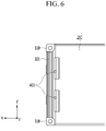
- Fig. 6 is a plan view showing a lower surface of the battery module of Fig. 5 .
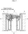
- Fig. 7 is a cross-sectional view taken along the cutting line "B" of Fig. 5 .
- the battery module 100 includes a battery cell stack 120 in which a plurality of battery cells 110 are stacked; and a module frame 200 for housing the battery cell stack 120, wherein a venting part 400 is formed on the lower surface of the module frame 200.
- the venting part means a part for discharging heat or gas inside the battery module 100.
- the battery cell 110 is preferably a pouch-type battery cell.
- the battery cell 110 according to embodiments of the present disclosure has a structure in which two electrode leads 111 and 112 face each other and protrude from one end 114a and the other end 114b of the cell main body 113, respectively. More specifically, the electrode leads 111 and 112 are connected to an electrode assembly (not shown), and protrude from the electrode assembly (not shown) to the outside of the battery cell 110. Meanwhile, the battery cell 110 can be manufactured by joining both ends 114a and 114b of the cell case 114 and one side part 114c connecting them in a state in which the electrode assembly (not shown) is housed in a cell case 114.
- the battery cell 110 has a total of three sealing parts 114sa, 114sb and 114sc, the sealing part 114sa, 114sb and 114sc have a structure sealed by a method such as heat fusion, and the remaining other side part may be formed of a connection part 115.
- the cell case 114 may be formed of a laminated sheet containing a resin layer and a metal layer.
- connection part 115 may extend long along one edge of the battery cell 110, and a protrusion part 110p of the battery cell 110 called a bat-ear may be formed at an end of the connection part 115.
- a terrace part 116 may be formed between the electrode leads 111 and 112 and the cell main body 113. That is, the battery cell 110 includes a terrace part 116 formed to extend from the cell case 114 in a direction in which the electrode leads 111 and 112 protrude.
- the battery cell 110 may be provided in plurality, and the plurality of battery cells 110 may be stacked so as to be electrically connected to each other, thereby forming a battery cell stack 120.
- An upper plate 130 may be located on the upper side of the battery cell stack 120, and a bus bar frame 140 may be located on a front surface and a rear surface of the battery cell stack 120 in the direction in which the electrode leads 111 and 112 protrude, respectively.
- the battery cell stack 120, the upper plate 130, and the bus bar frame 140 may be housed together in the module frame 200.
- a thermal conductive resin may be injected between the battery cell stack 120 and the lower surface of the module frame 200, and a thermal conductive resin layer (not shown) may be formed between the battery cell stack 120 and the lower surface of the module frame 200 through the injected thermal conductive resin.
- a thermal conductive resin layer (not shown) may be formed between the battery cell stack 120 and the lower surface of the module frame 200 through the injected thermal conductive resin.
- a bus bar frame 140 can be located on the front surface and the rear surface of the battery cell stack 120, respectively, to cover the battery cell stack 120 and at the same time, guide the connection between the battery cell stack 120 and an external device.
- a bus bar 141 and a terminal bus bar 142 may be mounted on the bus bar frame 140.
- the electrode leads 111 and 112 of the battery cells 110 may pass through a slit formed in the bus bar frame 140 and then be curved to be joined to the bus bar 141 or the terminal bus bar 142.
- the battery cells 110 constituting the battery cell stack 120 may be connected in series or in parallel via the bus bar 141, and the battery cells 110 may be electrically connected to an external device or circuit through the terminal bus bar 142 exposed to the outside of the battery module 100.
- a connector may be mounted on the bus bar frame 140, and the temperature or voltage data of the battery cell 110 measured through a sensing assembly (not shown) may be transferred to an external BMS (Battery Management System) or the like through a connector (not shown).
- BMS Battery Management System
- the end plates 301 and 302 are formed so as to cover the front surface and the rear surface of the battery cell stack 120. Specifically, the first end plate 301 and the second end plate 302 may be located on the front surface and the rear surface of the battery cell stack 120 , respectively.
- the end plates 301 and 302 can protect the bus bar frame 140 and various electrical components connected thereto from external impacts, and for this purpose, it needs to have a predetermined strength and can contain a metal such as aluminum.
- the end plates 301 and 302 are formed with a terminal bus bar opening 320 and a connector opening 330 for connecting a terminal bus bar 142 mounted on the bus bar frame 140 and the connector (not shown) to the outside, and gas or heat generated from the battery cell 110 can be discharged to the outside of the battery module 100 through the openings 320 and 330.
- the end plates 301 and 302 and the module frame 200 are joined by welding, and the plurality of battery cells 110 located inside the module frame 200 and the end plates 301 and 302 can be interrupted from being connected to the outside except for the above-mentioned openings 320 and 330, through the joining structure of the end plates 301 and 302 and the module frame 200 sealed by welding.
- the conventional battery module can discharge high-temperature heat, gas, or flame generated in the battery cell through the openings as described above.
- the high-temperature heat, gas, and flame ejected from the battery module may damage adjacent battery modules.
- a venting part 400 can be formed on the lower surface of the module frame 200 according to embodiments of the present disclosure, thereby dispensing heat, gas, flame, etc. discharged through the openings 320 and 330.
- the venting part 400 may have a hole structure formed on the lower surface of the module frame 200.
- the discharge path inside the battery module can be diversified through the venting part 400, thereby preventing a phenomenon in which the discharge is concentrated only to a part of the battery module 100 at the time of ignition, and dispersing the discharge of high-temperature heat, gases and flame.
- the venting part 400 is formed adjacent to the portion where the terrace part 116 is located rather than to the cell main body 113. A lot of heat is generated in the electrode leads 111 and 112 of the battery cells 110 and the terrace part 116 adjacent thereto, and as the sealing of the terrace part 116 is released due to the pressure change inside the battery cell 110, high-temperature heat, gas, and flame can be discharged.
- the venting part 400 according to embodiments of the present disclosure is formed adjacent to the part where the terrace part 116 is located rather than to the cell main body 113, so that high-temperature heat, gas, and flame may be immediately discharged to the outside of the battery module 100.
- the venting part 400 may be formed at a position corresponding to the terrace part 116.
- venting part 400 since the venting part 400 according to embodiments of the present disclosure is formed on the lower surface of the module frame 200, it is possible to prevent a phenomenon in which foreign matter floating in the air enters the inside of the battery module 100 via the venting part 400.
- venting parts 500 and 600 according to modified embodiments of the present disclosure will be described with reference to Figs. 8 and 9 .
- Figs. 8 and 9 are cross-sectional views of battery modules according to modified embodiments of the present disclosure, respectively.
- the venting parts 500 and 600 may be formed so as to discharge gas in a direction of an end plate located farther from the venting parts 500 and 600 among the first end plate 301 and the second end plate 302.
- the venting parts 500 and 600 located close to the first end plate 301 may be formed so as to discharge gas in the direction of the second end plate 302 located further away.
- venting parts 500 and 600 are formed at positions corresponding to the portion where the terrace part 116 is located, but the first end plate 301 is closer to the venting parts 500 and 600 than the second end plate 302 located on the opposite side of the reference of the battery cell stack 120. Therefore, when gas is discharged in the direction of the first end plate 301, high-temperature heat, gas, and flame can be emitted to other battery modules adjacent to the first end plate 301, thereby causing damage.
- the venting parts 500 and 600 are preferably formed so as to discharge gas in the direction of the second end plate 302. This will be described again with reference to Fig. 12 below.
- the venting part 500 may have a hole structure formed on the lower surface of the module frame 200 , and further may have a hole structure that obliquely penetrates the lower surface of the module frame 200.
- the inner inlet port of the obliquely penetrated venting part 500 is formed closer to the first end plate 301 than to the outer outlet port, and the outer outlet port may be formed closer to the second end plate 302 than to the inner inlet port.
- the venting part 500 may have an inclined direction getting closer to an end plate located further from the venting part 500 among the first end plate 301 and the second end plate 302.
- venting part 500 has the advantages in that it has a through-hole structure, does not require a separate additional space, and can impart the directionality of the discharged gas by penetrating the module frame 200.
- the venting part 600 may include an inlet port 610 formed on the lower surface of the module frame 200 and facing one surface of the battery cell along the stacking direction of the battery cell stack, an outlet port 620 for discharging gas that has flowed in through the inlet port 610, and a connection part 630 for connecting the inlet port 610 and the outlet port 620.
- the outlet port 620 may be formed in a direction perpendicular to the inlet port 610. Further, the connection part 630 may have a shape protruding from the lower surface of the module frame 200, and may be formed to be inclined. Therefore, the outlet port 620 may also be formed on the outside of the lower surface of the module frame 200.
- the venting part 600 may more reliably guide heat or gas inside the battery module toward the second end plate 302. That is, it has the advantage of more reliably imparting the directionality of heat or gas.
- the connection part 630 may perform the role as a kind of cover and thus, prevent foreign matter from entering the inside of the battery module.
- Fig. 10 is a perspective view showing a state in which a battery module according to embodiments of the present disclosure is mounted on a pack frame 1100.
- a module mounting part 310 may be formed on the end plates 301 and 302 so that the battery module 100 can be mounted and fixed to a pack frame 1100 of the battery pack.
- the number of the module mounting parts 310 is not limited, but it is preferable that for stable mounting of the battery module 100, two are formed on both sides of the first end plate 301, and two on both sides of the second end plate 302, and thus, a total of four is formed.
- the support member 340 may be inserted into the module mounting part 310.
- a mounting hole 311 may be formed in the module mounting part 310, and the support member 340 may be inserted into the mounting hole 311.
- a through hole may be formed in the bottom part 1110 of the pack frame 1100, and one end of the support member 340 that has passed through the mounting hole 311 may be joined to the through hole of the bottom part 1110.
- one end of the support member 340 may be provided in a bolt shape and joined with a nut-shaped through hole of the bottom part 1110.
- the joining is not limited to the bolt and nut joining, and may be implemented through various embodiments.
- the support member 340 can be cylindrical so that it can be inserted into the mounting hole 311 of the module mounting part 310.
- a head part 341 may be formed at the other end opposite to the one end of the support member 340.
- the head part 341 is formed to have a wider radius than the mounting hole 311, so that it is not inserted into the mounting hole 311, and the end plates 301 and 302 can be closely adhered and fixed to the bottom part 1110. Through this, the battery module 100 may be mounted and fixed to the pack frame 1100.
- the height of the support member 340 is set to be slightly longer, and the lower surface of the module frame 200 is spaced apart from the bottom part1110 of the pack frame 1100 by a predetermined distance d1.
- a fixing member such as a nut surrounding the support member 340 can be provided at the lower end of the module mounting part 310, thereby preventing the battery module 100 including the end plates 301 and 302 from moving downward. That is, the fixing member that maintains the separation distance by a predetermined interval d1 may be provided.
- venting parts 400, 500 and 600 are formed on the lower surface of the module frame 200 and heat or gas is discharged through the lower surface of the module frame 200, it is preferable to separate the lower surface of the module frame 200 from the bottom part 1110 of the pack frame 1100, thereby providing a space through which heat or gas is discharged.
- venting parts 500 and 600 of Figs. 8 and 9 induce the discharge in the direction from the first end plate 301 to the second end plate 302, it is preferable that the lower surface of the module frame 200 is spaced apart from the bottom part 1110 of the pack frame 1100 as described above.
- venting part 600 of Fig. 9 forms a structure in which the connection part 630 and the outlet port 620 protrude, it may be more preferable that the lower surface of the module frame 200 is spaced apart from the bottom part 1110 of the pack frame 1100.
- (a) and (b) of Fig. 11 are cross-sectional views of a battery module in which a fulcrum member 210 is formed, respectively, in accordance with a modified embodiment of the present invention.
- a fulcrum member 210 projecting downward can be formed on the lower surface of the module frame 200.
- the lower surface of the module frame 200 may be spaced apart from the bottom part of the pack frame. Accordingly, a space for discharging heat or gas is provided, and it can facilitate movement of the discharged heat or gas in the direction from the first end plate 301 to the second end plate 302.
- the number of the fulcrum members 210 is not particularly limited, but it is preferable to have a plurality of fulcrum members in order to stably support the battery module, and it is more preferable to evenly dispose them in all areas of the lower surface of the module frame 200.
- the venting parts 500 and 600 and the fulcrum member 210 are shown together in (a) and (b) of Fig. 11 , but in consideration of the path of heat or gas, the fulcrum member 210 is preferably formed to be displaced from the venting parts 500 and 600. Specifically, it is preferable that the position of the venting parts 500 and 600 and the position of the fulcrum member 210 do not coincide with each other in the direction parallel to the surface of the cell body 113 (direction parallel to the x-axis in Fig. 5 ). This is for preventing the fulcrum member 210 from blocking the heat or gas discharged from the venting parts 500 and 600.
- the material or the forming method of the fulcrum member 210 are not particularly limited, and it is preferable to have a predetermined strength so as to be able to support the battery module.
- the fulcrum member 210 may have a configuration integrated with the module frame 200. Alternatively, it may have a configuration formed by joining a member such as a metal to the lower surface of the module frame 200.
- the number of the venting parts 400, 500 and 600 according to embodiments of the present disclosure is not particularly limited as described above, and may be one, or may be configured in a plurality. However, when a plurality of venting parts 400, 500 and 600 are formed, it is preferable that plurality of venting parts 400, 500 and 600 are arranged in a direction parallel to the direction in which the battery cells 110 are stacked so as to correspond to the position of the terrace part 116 of the battery cells 110 constituting the battery cell stack 120.
- the direction in which the battery cells 110 are stacked refers to a direction perpendicular to the surface of the cell body 113, that is, a direction parallel to the y-axis in Fig. 5 .
- the module frame 200 may have a mono frame structure or a structure in which an upper cover is joined to a U-shaped frame.
- the mono frame may be in the form of a metal plate in which the upper surface, the lower surface and both side surfaces are integrated, and may be manufactured by extrusion molding.
- the upper cover in the case of a structure in which the upper cover is joined to the U-shaped frame, it can be formed by joining the upper cover to the upper side of a U-shaped frame, which is a metal plate material having a lower surface and both side surfaces integrated, and it can be manufactured by press molding.
- the venting parts 400 and 500 of the hole structure may be applied to both a mono frame manufactured by extrusion molding and a U-shaped frame manufactured by press molding.
- the venting part 600 having a protruding structure is easier to be mounted on a U-shaped frame manufactured by press molding rather than a mono frame manufactured by extrusion molding.
- the venting part 600 of the protruding structure it can be formed by forming a through hole in the lower surface of the module frame 200 and joining the connection part 630 and the outlet port 620 to the lower surface.
- the venting part 600 is also applicable to a mono frame manufactured by extrusion molding.
- Fig. 12 is a top plan view of a battery pack 1000 according to embodiments of the present disclosure.
- the battery pack 1000 may include two or more of the battery modules 100a and 100b described above.
- the battery modules 100a and 100b may be housed in the pack frame 1100, and may be mounted together with various control and protection systems such as BMS (battery management system) and a cooling system.
- BMS battery management system
- the first battery module 100a and the second battery module 100b may have openings 320a, 330a, 320b and 330b formed on surfaces facing each other.
- the first end plate 301a of the first battery module 100a and the first end plate 301b of the second battery module 100b may face each other.
- the terminal bus bar opening 320a and the connector opening 330a may be formed in the first end plate 301a of the first battery module 100a.
- a terminal bus bar opening 320b and a connector opening 330b may be formed in the first end plate 301b of the second battery module 100b.
- the battery modules 100a and 100b can provide the above-mentioned venting part on the lower surface thereof, thereby reducing heat, gas, and flames emitted through the openings 320a, 330a, 320b and 330b.
- venting parts 500 and 600 shown in Fig. 8 or Fig. 9 may be provided in the battery modules 100a and 100b.
- the first battery module 100a can induce heat, gas, flame, etc. to be discharged in a direction opposite to the direction in which the second battery module 100b is located
- the second battery module 100b can induce heat, gas, and flame to be discharged in a direction opposite to the direction in which the first battery module 100a is located. That is, damage that may be applied between the facing battery modules 100a and 100b can be minimized.
- the battery modules 100a and 100b may be spaced apart from the bottom part 1110 of the pack frame 1100.
- the battery modules 100a and 100b include a module mounting part 310 and a support member 340 shown in Fig. 10 , or include a fulcrum member 210 shown in (a) and (b) of Fig. 11 . Accordingly, a space for discharging heat, gas, flame, etc. may be provided inside the battery pack 1000.
- the battery module or the battery pack according to embodiments of the present disclosure described above can be applied to various devices. Specifically, it can be applied to vehicle means such as an electric bike, an electric vehicle, and a hybrid electric vehicle, and may be applied to various devices capable of using a secondary battery, without being limited thereto.
- vehicle means such as an electric bike, an electric vehicle, and a hybrid electric vehicle
- various devices capable of using a secondary battery without being limited thereto.
Landscapes
- Chemical & Material Sciences (AREA)
- Chemical Kinetics & Catalysis (AREA)
- Electrochemistry (AREA)
- General Chemical & Material Sciences (AREA)
- Engineering & Computer Science (AREA)
- Aviation & Aerospace Engineering (AREA)
- Battery Mounting, Suspending (AREA)
- Gas Exhaust Devices For Batteries (AREA)
- Connection Of Batteries Or Terminals (AREA)
- Sealing Battery Cases Or Jackets (AREA)
Abstract
Description
- This application claims the benefit of
Korean Patent Application No. 10-2020-0039762 filed on April 1, 2020 - The present disclosure relates to a battery module and a battery pack including the same, and more particularly, to a battery module having enhanced stability, and a battery pack including the same.
- A secondary battery has attracted much attention as an energy source in various products such as a mobile device and an electric vehicle. The secondary battery is a potent energy resource that can replace the use of existing products using fossil fuels, and is in the spotlight as an environment-friendly energy source because it does not generate by-products due to energy use.
- Recently, along with a continuous rise of the necessity for a large-capacity secondary battery structure, including the utilization of the secondary battery as an energy storage source, there is a growing demand for a battery pack of a multi-module structure which is an assembly of battery modules in which a plurality of secondary batteries are connected in series or in parallel.
- Meanwhile, when a plurality of battery cells are connected in series or in parallel to configure a battery pack, a method of configuring a battery module composed of a plurality of battery cells and then adding other components to at least one battery module to configure a battery pack is common. Since the battery cells constituting these middle or large-sized battery modules are composed of chargeable/dischargeable secondary batteries, such a high-output and large-capacity secondary battery generates a large amount of heat in a charging and discharging process.
- The battery module may include a battery cell stack in which a plurality of battery cells are stacked, a frame for housing the battery cell stack, and end plates for covering the front and rear surfaces of the battery cell stack.
-
Fig. 1 is a view showing the appearance of a battery module mounted on a conventional battery pack at the time of ignition.Fig. 2 is a section taken along line A-A ofFig. 1 and is a cross-sectional view showing the appearance of a flame that affects adjacent battery modules during ignition of a battery module mounted on a conventional battery pack. - Referring to
Figs. 1 and2 , the conventional battery module includes a battery cell stack in which a plurality ofbattery cells 10 are stacked, aframe 20 for housing the battery cell stack,end plates 30 formed on the front and rear surfaces of the battery cell stack,terminal bus bars 40 formed so as to protrude to the outside of theend plates 30, and the like. - The
frame 20 and theend plate 30 can be joined so as to be sealed by welding. When the internal pressure of thebattery cells 10 increases during overcharge of the battery module to exceed a limit value of the fusion strength of the battery cell, high-temperature heat, gas, and flame generated in thebattery cells 10 can be discharged to the outside of thebattery cell 10. - At this time, the high-temperature heat, gas and flame may be discharged through the openings formed in the
end plates 30. However, in a battery pack structure in which a plurality of battery modules are arranged so that theend plates 30 face each other, the high-temperature heat, gas and flame ejected from the battery module may affect an adjacent battery module. Thereby, theterminal bus bar 40 formed on theend plates 30 of the adjacent battery module may be damaged, and high-temperature heat, gas, and flame may enter the inside of the adjacent battery module via the openings formed in theend plates 30 of the adjacent battery module to damage the plurality ofbattery cells 10. - It is an object of the present disclosure to provide a battery module capable of dispersing high-temperature heat and flame discharged when an ignition phenomenon occurs in the battery module, and a battery pack including the same.
- The objects of the present disclosure are not limited to the aforementioned objects, and other objects which are not described herein should be clearly understood by those skilled in the art from the following detailed description.
- According to embodiments of the present disclosure, there is provided a battery module comprising: a battery cell stack in which a plurality of battery cells are stacked; and a module frame for housing the battery cell stack, wherein a venting part is formed on a lower surface of the module frame, wherein the battery cell comprises: a cell main body; electrode leads formed to protrude from both ends of the cell main body; and a terrace part formed to extend from the cell case in a direction in which the electrode leads protrude, wherein the venting part is formed adjacent to a portion where the terrace part is located rather than to the cell main body.
- The venting part may be formed at a position corresponding to a portion where the terrace part is located.
- The battery module may further include a first end plate and a second end plate located on a front surface and a rear surface of the battery cell stack, respectively.
- The venting part may have a hole structure formed on the lower surface of the module frame.
- The hole structure may obliquely penetrate the lower surface of the module frame.
- The hole structure may have an inclined direction getting closer to an end plate that is located farther from the venting part among the first end plate and the second end plate.
- The venting part may include an inlet port formed on the lower surface of the module frame and facing the battery cell stack, an outlet port for discharging gas that has flowed in through the inlet port, and a connection part for connecting the inlet port and the outlet port.
- The outlet port may be formed in a direction perpendicular to the inlet port.
- The connection part may have a shape protruding from the lower surface of the module frame.
- The venting part may be formed so as to discharge gas in a direction of the end plate located farther from the venting part among the first end plate and the second end plate.
- The first end plate and the second end plate may include a module mounting part for fixing the battery module, a support member may be inserted into the module mounting part, and the lower surface of the module frame may be spaced apart from a bottom part of a pack frame by the support member.
- A fulcrum member protruding downward may be formed on the lower surface of the module frame.
- According to embodiments of the present disclosure, there is provided a battery pack comprising two or more of the battery modules, wherein among the battery modules, a first battery module and a second battery module may have openings formed on surfaces facing each other.
- The venting part of the first battery module may be formed so as to discharge gas in a direction opposite to a direction in which the second battery module is located.
- The battery pack may further include a pack frame for housing the battery modules, wherein the battery modules may be spaced apart from the bottom part of the pack frame.
- A battery module and a battery pack including the same according to embodiments of the present disclosure can disperse high-temperature heat, gas, and flame generated at the time of ignition of the battery module through a venting part formed on the lower surface of the module frame, thereby minimizing a damage applied to battery module terminals and the portions of plural battery cells facing the battery module.
- The effects of the present disclosure are not limited to the effects mentioned above and additional other effects not described above will be clearly understood from the description of the appended claims by those skilled in the art.
-
-
Fig. 1 is a view showing the appearance of a battery module mounted on a conventional battery pack at the time of ignition; -
Fig. 2 shows a section taken along line A-A inFIG. 1 and is a cross-sectional view showing the appearance of a flame that affects adjacent battery modules during ignition of a battery module mounted on a conventional battery pack; -
Fig. 3 is an exploded perspective view of a battery module according to embodiments of the present disclosure; -
Fig. 4 is a perspective view of a battery cell contained in the battery module ofFig. 3 ; -
Fig. 5 is a perspective view showing a state in which the battery module ofFIG. 3 has been joined; -
Fig. 6 is a plan view showing a lower surface of the battery module ofFig. 5 ; -
Fig. 7 is a cross-sectional view taken along the cutting line "B" ofFig. 5 ; -
Figs. 8 and9 are cross-sectional views of battery modules according to modified embodiments of the present disclosure, respectively; -
Fig. 10 is a perspective view showing a state in which a battery module according to embodiments of the present disclosure is mounted on a pack frame;
(a) and (b) ofFig. 11 are cross-sectional views of a battery module in which a fulcrum member is formed, respectively; and -
Fig. 12 is a top plan view of a battery pack according to embodiments of the present disclosure. - Hereinafter, various embodiments of the present disclosure will be described in detail with reference to the accompanying drawings so that those skilled in the art can easily implement them. The present disclosure may be modified in various different ways, and is not limited to the embodiments set forth herein.
- A description of parts not related to the description will be omitted herein for clarity, and like reference numerals designate like elements throughout the description.
- Further, in the drawings, the size and thickness of each element are arbitrarily illustrated for convenience of description, and the present disclosure is not necessarily limited to those illustrated in the drawings. In the drawings, the thickness of layers, regions, etc. are exaggerated for clarity. In the drawings, for convenience of description, the thicknesses of some layers and regions are exaggerated.
- In addition, it will be understood that when an element such as a layer, film, region, or plate is referred to as being "on" or "above" another element, it can be directly on the other element or intervening elements may also be present. In contrast, when an element is referred to as being "directly on" another element, it means that other intervening elements are not present. Further, the word "on" or "above" means disposed on or below a reference portion, and does not necessarily mean being disposed on the upper end of the reference portion toward the opposite direction of gravity.
- Further, throughout the description, when a portion is referred to as "including" a certain component, it means that the portion can further include other components, without excluding the other components, unless otherwise stated.
- Further, throughout the description, when referred to as "planar", it means when a target portion is viewed from the upper side, and when referred to as "cross-sectional", it means when a target portion is viewed from the side of a cross section cut vertically.
- Hereinafter, a battery module according to embodiments of the present disclosure will be described with reference to
Figs. 3 to 7 . -
Fig. 3 is an exploded perspective view of a battery module according to embodiments of the present disclosure.Fig. 4 is a perspective view of a battery cell contained in the battery module ofFig. 3 .Fig. 5 is a perspective view showing a state in which the battery module ofFig. 3 has been joined.Fig. 6 is a plan view showing a lower surface of the battery module ofFig. 5 .Fig. 7 is a cross-sectional view taken along the cutting line "B" ofFig. 5 . - With reference to
Figs. 3 to 7 , thebattery module 100 according to embodiments of the present disclosure includes abattery cell stack 120 in which a plurality ofbattery cells 110 are stacked; and amodule frame 200 for housing thebattery cell stack 120, wherein a ventingpart 400 is formed on the lower surface of themodule frame 200. As used herein, the venting part means a part for discharging heat or gas inside thebattery module 100. - Referring to
Fig. 4 , thebattery cell 110 is preferably a pouch-type battery cell. For example, thebattery cell 110 according to embodiments of the present disclosure has a structure in which two electrode leads 111 and 112 face each other and protrude from oneend 114a and theother end 114b of the cellmain body 113, respectively. More specifically, the electrode leads 111 and 112 are connected to an electrode assembly (not shown), and protrude from the electrode assembly (not shown) to the outside of thebattery cell 110. Meanwhile, thebattery cell 110 can be manufactured by joining bothends cell case 114 and oneside part 114c connecting them in a state in which the electrode assembly (not shown) is housed in acell case 114. In other words, thebattery cell 110 according to embodiments of the present disclosure has a total of three sealing parts 114sa, 114sb and 114sc, the sealing part 114sa, 114sb and 114sc have a structure sealed by a method such as heat fusion, and the remaining other side part may be formed of aconnection part 115. Thecell case 114 may be formed of a laminated sheet containing a resin layer and a metal layer. - In addition, the
connection part 115 may extend long along one edge of thebattery cell 110, and aprotrusion part 110p of thebattery cell 110 called a bat-ear may be formed at an end of theconnection part 115. Further, while thecell case 114 is sealed with the protruding electrode leads 111 and 112 being interposed therebetween, aterrace part 116 may be formed between the electrode leads 111 and 112 and the cellmain body 113. That is, thebattery cell 110 includes aterrace part 116 formed to extend from thecell case 114 in a direction in which the electrode leads 111 and 112 protrude. - The
battery cell 110 may be provided in plurality, and the plurality ofbattery cells 110 may be stacked so as to be electrically connected to each other, thereby forming abattery cell stack 120. Anupper plate 130 may be located on the upper side of thebattery cell stack 120, and a bus bar frame 140 may be located on a front surface and a rear surface of thebattery cell stack 120 in the direction in which the electrode leads 111 and 112 protrude, respectively. Thebattery cell stack 120, theupper plate 130, and the bus bar frame 140 may be housed together in themodule frame 200. - A thermal conductive resin may be injected between the
battery cell stack 120 and the lower surface of themodule frame 200, and a thermal conductive resin layer (not shown) may be formed between thebattery cell stack 120 and the lower surface of themodule frame 200 through the injected thermal conductive resin. Through themodule frame 200, thebattery cell stack 120 housed inside themodule frame 200 and the electrical components connected thereto can be protected from external physical impact. - A bus bar frame 140 can be located on the front surface and the rear surface of the
battery cell stack 120, respectively, to cover thebattery cell stack 120 and at the same time, guide the connection between thebattery cell stack 120 and an external device. Specifically, abus bar 141 and aterminal bus bar 142 may be mounted on the bus bar frame 140. The electrode leads 111 and 112 of thebattery cells 110 may pass through a slit formed in the bus bar frame 140 and then be curved to be joined to thebus bar 141 or theterminal bus bar 142. Thebattery cells 110 constituting thebattery cell stack 120 may be connected in series or in parallel via thebus bar 141, and thebattery cells 110 may be electrically connected to an external device or circuit through theterminal bus bar 142 exposed to the outside of thebattery module 100. Further, a connector (not shown) may be mounted on the bus bar frame 140, and the temperature or voltage data of thebattery cell 110 measured through a sensing assembly (not shown) may be transferred to an external BMS (Battery Management System) or the like through a connector (not shown). - The
end plates battery cell stack 120. Specifically, thefirst end plate 301 and thesecond end plate 302 may be located on the front surface and the rear surface of thebattery cell stack 120 , respectively. Theend plates - The
end plates bus bar opening 320 and aconnector opening 330 for connecting aterminal bus bar 142 mounted on the bus bar frame 140 and the connector (not shown) to the outside, and gas or heat generated from thebattery cell 110 can be discharged to the outside of thebattery module 100 through theopenings end plates module frame 200 are joined by welding, and the plurality ofbattery cells 110 located inside themodule frame 200 and theend plates openings end plates module frame 200 sealed by welding. - The conventional battery module can discharge high-temperature heat, gas, or flame generated in the battery cell through the openings as described above. However, in the battery pack structure in which a plurality of battery modules are arranged so that the end plates face each other, the high-temperature heat, gas, and flame ejected from the battery module may damage adjacent battery modules.
- Thus, a venting
part 400 can be formed on the lower surface of themodule frame 200 according to embodiments of the present disclosure, thereby dispensing heat, gas, flame, etc. discharged through theopenings part 400 may have a hole structure formed on the lower surface of themodule frame 200. The discharge path inside the battery module can be diversified through the ventingpart 400, thereby preventing a phenomenon in which the discharge is concentrated only to a part of thebattery module 100 at the time of ignition, and dispersing the discharge of high-temperature heat, gases and flame. - Further, the venting
part 400 is formed adjacent to the portion where theterrace part 116 is located rather than to the cellmain body 113. A lot of heat is generated in the electrode leads 111 and 112 of thebattery cells 110 and theterrace part 116 adjacent thereto, and as the sealing of theterrace part 116 is released due to the pressure change inside thebattery cell 110, high-temperature heat, gas, and flame can be discharged. At this time, the ventingpart 400 according to embodiments of the present disclosure is formed adjacent to the part where theterrace part 116 is located rather than to the cellmain body 113, so that high-temperature heat, gas, and flame may be immediately discharged to the outside of thebattery module 100. In one example, the ventingpart 400 may be formed at a position corresponding to theterrace part 116. - Meanwhile, since the venting
part 400 according to embodiments of the present disclosure is formed on the lower surface of themodule frame 200, it is possible to prevent a phenomenon in which foreign matter floating in the air enters the inside of thebattery module 100 via the ventingpart 400. - Hereinafter, the venting
parts Figs. 8 and9 . -
Figs. 8 and9 are cross-sectional views of battery modules according to modified embodiments of the present disclosure, respectively. - Referring to
Figs. 8 and9 together withFig. 3 , the ventingparts parts first end plate 301 and thesecond end plate 302. As shown inFigs. 8 and9 , the ventingparts first end plate 301 may be formed so as to discharge gas in the direction of thesecond end plate 302 located further away. - The venting
parts terrace part 116 is located, but thefirst end plate 301 is closer to the ventingparts second end plate 302 located on the opposite side of the reference of thebattery cell stack 120. Therefore, when gas is discharged in the direction of thefirst end plate 301, high-temperature heat, gas, and flame can be emitted to other battery modules adjacent to thefirst end plate 301, thereby causing damage. In order to prevent this, the ventingparts second end plate 302. This will be described again with reference toFig. 12 below. - Referring to
Fig. 8 , the ventingpart 500 may have a hole structure formed on the lower surface of themodule frame 200 , and further may have a hole structure that obliquely penetrates the lower surface of themodule frame 200. - Specifically, the inner inlet port of the obliquely penetrated venting
part 500 is formed closer to thefirst end plate 301 than to the outer outlet port, and the outer outlet port may be formed closer to thesecond end plate 302 than to the inner inlet port. In other words, the ventingpart 500 may have an inclined direction getting closer to an end plate located further from the ventingpart 500 among thefirst end plate 301 and thesecond end plate 302. - By providing the structure as described above, it is possible to naturally impart directionality to heat or gas discharged through the venting
part 500. That is, it can be induced so as to discharge gas in the direction of thesecond end plate 302 located further away, thereby preventing damage to other battery modules adjacent to thefirst end plate 301. - Further, the venting
part 500 according to embodiments of the present disclosure has the advantages in that it has a through-hole structure, does not require a separate additional space, and can impart the directionality of the discharged gas by penetrating themodule frame 200. - Next, referring to
Fig. 9 , the ventingpart 600 may include aninlet port 610 formed on the lower surface of themodule frame 200 and facing one surface of the battery cell along the stacking direction of the battery cell stack, anoutlet port 620 for discharging gas that has flowed in through theinlet port 610, and aconnection part 630 for connecting theinlet port 610 and theoutlet port 620. - The
outlet port 620 may be formed in a direction perpendicular to theinlet port 610. Further, theconnection part 630 may have a shape protruding from the lower surface of themodule frame 200, and may be formed to be inclined. Therefore, theoutlet port 620 may also be formed on the outside of the lower surface of themodule frame 200. - Based on the structure as described above, the venting
part 600 according to embodiments of the present disclosure may more reliably guide heat or gas inside the battery module toward thesecond end plate 302. That is, it has the advantage of more reliably imparting the directionality of heat or gas. Further, theconnection part 630 may perform the role as a kind of cover and thus, prevent foreign matter from entering the inside of the battery module. -
Fig. 10 is a perspective view showing a state in which a battery module according to embodiments of the present disclosure is mounted on apack frame 1100. - Referring to
Fig. 10 together withFig. 5 , amodule mounting part 310 may be formed on theend plates battery module 100 can be mounted and fixed to apack frame 1100 of the battery pack. The number of themodule mounting parts 310 is not limited, but it is preferable that for stable mounting of thebattery module 100, two are formed on both sides of thefirst end plate 301, and two on both sides of thesecond end plate 302, and thus, a total of four is formed. - The
support member 340 may be inserted into themodule mounting part 310. Specifically, a mountinghole 311 may be formed in themodule mounting part 310, and thesupport member 340 may be inserted into the mountinghole 311. A through hole may be formed in thebottom part 1110 of thepack frame 1100, and one end of thesupport member 340 that has passed through the mountinghole 311 may be joined to the through hole of thebottom part 1110. In one example, one end of thesupport member 340 may be provided in a bolt shape and joined with a nut-shaped through hole of thebottom part 1110. However, the joining is not limited to the bolt and nut joining, and may be implemented through various embodiments. - Meanwhile, the
support member 340 can be cylindrical so that it can be inserted into the mountinghole 311 of themodule mounting part 310. Further, ahead part 341 may be formed at the other end opposite to the one end of thesupport member 340. Thehead part 341 is formed to have a wider radius than the mountinghole 311, so that it is not inserted into the mountinghole 311, and theend plates bottom part 1110. Through this, thebattery module 100 may be mounted and fixed to thepack frame 1100. - At this time, it is preferable that the height of the
support member 340 is set to be slightly longer, and the lower surface of themodule frame 200 is spaced apart from the bottom part1110 of thepack frame 1100 by a predetermined distance d1. In another example, although not specifically shown, a fixing member such as a nut surrounding thesupport member 340 can be provided at the lower end of themodule mounting part 310, thereby preventing thebattery module 100 including theend plates - In embodiments of the present disclosure, since the venting
parts module frame 200 and heat or gas is discharged through the lower surface of themodule frame 200, it is preferable to separate the lower surface of themodule frame 200 from thebottom part 1110 of thepack frame 1100, thereby providing a space through which heat or gas is discharged. - In particular, since the venting
parts Figs. 8 and9 induce the discharge in the direction from thefirst end plate 301 to thesecond end plate 302, it is preferable that the lower surface of themodule frame 200 is spaced apart from thebottom part 1110 of thepack frame 1100 as described above. In addition, since the ventingpart 600 ofFig. 9 forms a structure in which theconnection part 630 and theoutlet port 620 protrude, it may be more preferable that the lower surface of themodule frame 200 is spaced apart from thebottom part 1110 of thepack frame 1100.
(a) and (b) ofFig. 11 are cross-sectional views of a battery module in which afulcrum member 210 is formed, respectively, in accordance with a modified embodiment of the present invention. - Referring to (a) and (b) of
Fig. 11 , afulcrum member 210 projecting downward can be formed on the lower surface of themodule frame 200. - When the battery module is mounted on the pack frame through the
fulcrum member 210, the lower surface of themodule frame 200 may be spaced apart from the bottom part of the pack frame. Accordingly, a space for discharging heat or gas is provided, and it can facilitate movement of the discharged heat or gas in the direction from thefirst end plate 301 to thesecond end plate 302. - The number of the
fulcrum members 210 is not particularly limited, but it is preferable to have a plurality of fulcrum members in order to stably support the battery module, and it is more preferable to evenly dispose them in all areas of the lower surface of themodule frame 200. - For convenience of explanation, the venting
parts fulcrum member 210 are shown together in (a) and (b) ofFig. 11 , but in consideration of the path of heat or gas, thefulcrum member 210 is preferably formed to be displaced from the ventingparts parts fulcrum member 210 do not coincide with each other in the direction parallel to the surface of the cell body 113 (direction parallel to the x-axis inFig. 5 ). This is for preventing thefulcrum member 210 from blocking the heat or gas discharged from the ventingparts - The material or the forming method of the
fulcrum member 210 are not particularly limited, and it is preferable to have a predetermined strength so as to be able to support the battery module. Thefulcrum member 210 may have a configuration integrated with themodule frame 200. Alternatively, it may have a configuration formed by joining a member such as a metal to the lower surface of themodule frame 200. - Meanwhile, the number of the venting
parts parts parts battery cells 110 are stacked so as to correspond to the position of theterrace part 116 of thebattery cells 110 constituting thebattery cell stack 120. Here, the direction in which thebattery cells 110 are stacked refers to a direction perpendicular to the surface of thecell body 113, that is, a direction parallel to the y-axis inFig. 5 . - Referring back to
FIG. 3 , themodule frame 200 according to embodiments of the present disclosure may have a mono frame structure or a structure in which an upper cover is joined to a U-shaped frame. - First, the mono frame may be in the form of a metal plate in which the upper surface, the lower surface and both side surfaces are integrated, and may be manufactured by extrusion molding.
- Next, in the case of a structure in which the upper cover is joined to the U-shaped frame, it can be formed by joining the upper cover to the upper side of a U-shaped frame, which is a metal plate material having a lower surface and both side surfaces integrated, and it can be manufactured by press molding.
- As shown in
Fig. 7 orFig. 8 , the ventingparts - Meanwhile, as shown in
Fig. 9 , the ventingpart 600 having a protruding structure is easier to be mounted on a U-shaped frame manufactured by press molding rather than a mono frame manufactured by extrusion molding. However, in forming the ventingpart 600 of the protruding structure, it can be formed by forming a through hole in the lower surface of themodule frame 200 and joining theconnection part 630 and theoutlet port 620 to the lower surface. In this case, the ventingpart 600 is also applicable to a mono frame manufactured by extrusion molding. -
Fig. 12 is a top plan view of abattery pack 1000 according to embodiments of the present disclosure. - Referring to
Fig. 12 , thebattery pack 1000 according to embodiments of the present disclosure may include two or more of thebattery modules - The
battery modules pack frame 1100, and may be mounted together with various control and protection systems such as BMS (battery management system) and a cooling system. - The
first battery module 100a and thesecond battery module 100b may haveopenings - Specifically, the
first end plate 301a of thefirst battery module 100a and thefirst end plate 301b of thesecond battery module 100b may face each other. At this time, the terminalbus bar opening 320a and theconnector opening 330a may be formed in thefirst end plate 301a of thefirst battery module 100a. Further, a terminalbus bar opening 320b and aconnector opening 330b may be formed in thefirst end plate 301b of thesecond battery module 100b. - The
battery modules openings - In addition, the venting
parts Fig. 8 orFig. 9 may be provided in thebattery modules first battery module 100a can induce heat, gas, flame, etc. to be discharged in a direction opposite to the direction in which thesecond battery module 100b is located, and thesecond battery module 100b can induce heat, gas, and flame to be discharged in a direction opposite to the direction in which thefirst battery module 100a is located. That is, damage that may be applied between the facingbattery modules - Further, the
battery modules bottom part 1110 of thepack frame 1100. Specifically, thebattery modules module mounting part 310 and asupport member 340 shown inFig. 10 , or include afulcrum member 210 shown in (a) and (b) ofFig. 11 . Accordingly, a space for discharging heat, gas, flame, etc. may be provided inside thebattery pack 1000. - The terms representing directions such as the front side, the rear side, the left side, the right side, the upper side, and the lower side have been used in embodiments of the present disclosure, but the terms used are provided simply for convenience of description and may become different according to the location of an object or an observer.
- The battery module or the battery pack according to embodiments of the present disclosure described above can be applied to various devices. Specifically, it can be applied to vehicle means such as an electric bike, an electric vehicle, and a hybrid electric vehicle, and may be applied to various devices capable of using a secondary battery, without being limited thereto.
- The present disclosure has been described in detail with reference to exemplary embodiments thereof, but the scope of the present disclosure is not limited thereto and modifications and improvements made by those skilled in the part by using the basic concept of the present disclosure, which are defined in the following claims, also belong to the scope of the present disclosure.
-
- 100, 100a, 100b: battery module
- 110: battery cell
- 111, 112: electrode leads
- 113: cell main body
- 116: terrace part
- 120: battery cell stack
- 200: module frame
- 301: first end plate
- 302: second end plate
- 310: module mounting part
- 400, 500, 600: venting part
- 1000: battery pack
- 1100: pack frame
Claims (15)
- A battery module comprising:a battery cell stack in which a plurality of battery cells are stacked; anda module frame for housing the battery cell stack,wherein a venting part is formed on a lower surface of the module frame,wherein the battery cell comprises:a cell main body;electrode leads formed to protrude from both ends of the cell main body; anda terrace part formed to extend from the cell case in a direction in which the electrode leads protrude,wherein the venting part is formed adjacent to a portion where the terrace part is located rather than to the cell main body.
- The battery module of claim 1, wherein:
the venting part is formed at a position corresponding to a portion where the terrace part is located. - The battery module of claim 1, wherein
which further comprises a first end plate and a second end plate located on a front surface and a rear surface of the battery cell stack, respectively. - The battery module of claim 3, wherein:
the venting part has a hole structure formed on the lower surface of the module frame. - The battery module of claim 4, wherein:
the hole structure obliquely penetrates the lower surface of the module frame. - The battery module of claim 5, wherein:
the hole structure has an inclined direction getting closer to an end plate that is located farther from the venting part among the first end plate and the second end plate. - The battery module of claim 3, wherein:
the venting part comprises an inlet port formed on the lower surface of the module frame and facing the battery cell stack, an outlet port for discharging gas that has flowed in through the inlet port, and a connection part for connecting the inlet port and the outlet port. - The battery module of claim 7, wherein:
the outlet port is formed in a direction perpendicular to the inlet port. - The battery module of claim 7, wherein:
the connection part has a shape protruding from the lower surface of the module frame. - The battery module of claim 3, wherein:
the venting part is formed so as to discharge gas in a direction of the end plate located farther from the venting part among the first end plate and the second end plate. - The battery module of claim 3, wherein:the first end plate and the second end plate comprise a module mounting part for fixing the battery module,a support member is inserted into the module mounting part, andthe lower surface of the module frame is spaced apart from a bottom part of a pack frame by the support member.
- The battery module of claim 1, wherein:
a fulcrum member protruding downward is formed on the lower surface of the module frame. - A battery pack comprising two or more of the battery modules of claim 1,
wherein among the battery modules, a first battery module and a second battery module have openings formed on surfaces facing each other. - The battery pack of claim 13, wherein:
the venting part of the first battery module is formed so as to discharge gas in a direction opposite to a direction in which the second battery module is located. - The battery pack of claim 13, wherein:which further comprises a pack frame for housing the battery modules,wherein the battery modules are spaced apart from a bottom part of the pack frame.
Applications Claiming Priority (2)
| Application Number | Priority Date | Filing Date | Title |
|---|---|---|---|
| KR1020200039762A KR20210122512A (en) | 2020-04-01 | 2020-04-01 | Battery module and battery pack including the same |
| PCT/KR2021/002881 WO2021201454A1 (en) | 2020-04-01 | 2021-03-09 | Battery module and battery pack including same |
Publications (2)
| Publication Number | Publication Date |
|---|---|
| EP4057435A1 true EP4057435A1 (en) | 2022-09-14 |
| EP4057435A4 EP4057435A4 (en) | 2024-08-14 |
Family
ID=77928092
Family Applications (1)
| Application Number | Title | Priority Date | Filing Date |
|---|---|---|---|
| EP21780844.3A Pending EP4057435A4 (en) | 2020-04-01 | 2021-03-09 | Battery module and battery pack including same |
Country Status (6)
| Country | Link |
|---|---|
| US (1) | US20220407172A1 (en) |
| EP (1) | EP4057435A4 (en) |
| JP (1) | JP2023502612A (en) |
| KR (1) | KR20210122512A (en) |
| CN (1) | CN114730958B (en) |
| WO (1) | WO2021201454A1 (en) |
Families Citing this family (1)
| Publication number | Priority date | Publication date | Assignee | Title |
|---|---|---|---|---|
| WO2024122901A1 (en) * | 2022-12-05 | 2024-06-13 | 주식회사 엘지에너지솔루션 | Battery module, and battery pack and vehicle comprising same |
Family Cites Families (10)
| Publication number | Priority date | Publication date | Assignee | Title |
|---|---|---|---|---|
| JP5632402B2 (en) * | 2004-11-30 | 2014-11-26 | 日本電気株式会社 | Film exterior electrical device assembly |
| KR101029837B1 (en) * | 2009-01-06 | 2011-04-15 | 주식회사 엘지화학 | Novel battery module and medium and large battery packs comprising the same |
| EP2738834B1 (en) * | 2011-07-29 | 2019-03-20 | Panasonic Intellectual Property Management Co., Ltd. | Battery pack |
| US20160218336A1 (en) * | 2015-01-28 | 2016-07-28 | Motorola Solutions, Inc | Method and apparatus for assembling cells in a battery pack to control thermal release |
| JP6645500B2 (en) * | 2015-07-22 | 2020-02-14 | 株式会社村田製作所 | Battery module |
| KR102101906B1 (en) * | 2016-10-21 | 2020-04-17 | 주식회사 엘지화학 | Battery Pack Comprising Coupling Member Having Assembling Guide Function |
| JP6545212B2 (en) * | 2017-03-17 | 2019-07-17 | 本田技研工業株式会社 | Battery pack |
| KR102270231B1 (en) * | 2017-04-04 | 2021-06-25 | 주식회사 엘지에너지솔루션 | Battery pack and vehicle comprising the battery pack |
| KR102096983B1 (en) * | 2017-09-08 | 2020-04-03 | 주식회사 엘지화학 | Battery module with a structure to break a connector using venting gas |
| KR102330378B1 (en) * | 2018-04-20 | 2021-11-22 | 주식회사 엘지에너지솔루션 | Battery Pack with degassing flow path |
-
2020
- 2020-04-01 KR KR1020200039762A patent/KR20210122512A/en not_active Application Discontinuation
-
2021
- 2021-03-09 US US17/779,282 patent/US20220407172A1/en active Pending
- 2021-03-09 JP JP2022527810A patent/JP2023502612A/en active Pending
- 2021-03-09 EP EP21780844.3A patent/EP4057435A4/en active Pending
- 2021-03-09 WO PCT/KR2021/002881 patent/WO2021201454A1/en unknown
- 2021-03-09 CN CN202180006420.9A patent/CN114730958B/en active Active
Also Published As
| Publication number | Publication date |
|---|---|
| JP2023502612A (en) | 2023-01-25 |
| WO2021201454A1 (en) | 2021-10-07 |
| KR20210122512A (en) | 2021-10-12 |
| EP4057435A4 (en) | 2024-08-14 |
| US20220407172A1 (en) | 2022-12-22 |
| CN114730958A (en) | 2022-07-08 |
| CN114730958B (en) | 2024-01-23 |
Similar Documents
| Publication | Publication Date | Title |
|---|---|---|
| EP4012830A1 (en) | Battery module and battery pack including same | |
| US20200176739A1 (en) | Battery pack | |
| KR102433361B1 (en) | Battery module and battery pack including the same | |
| EP4024594A1 (en) | Battery module and battery pack including same | |
| EP4007057A1 (en) | Battery module and battery pack including same | |
| KR20210127316A (en) | Battery module and battery pack including the same | |
| EP4024595A1 (en) | Battery pack and device comprising same | |
| JP7479488B2 (en) | Battery pack and device including same | |
| CN220253415U (en) | Battery module and battery pack including the same | |
| JP7472396B2 (en) | Battery module and battery pack including same | |
| EP4057435A1 (en) | Battery module and battery pack including same | |
| KR20220000638A (en) | Battery module and battery pack including the same | |
| US20230124214A1 (en) | Battery module and battery pack including the same | |
| US20240072374A1 (en) | Battery module and battery pack comprising same | |
| KR20230007739A (en) | Battery module and battery pack including the same | |
| US20230097757A1 (en) | Battery module and battery pack including the same | |
| US20230378599A1 (en) | Battery module and battery pack including the same | |
| EP4435954A1 (en) | Battery pack and device including same | |
| KR20230109945A (en) | Battery Pack | |
| KR20240117478A (en) | Battery module and Battery Pack including the same |
Legal Events
| Date | Code | Title | Description |
|---|---|---|---|
| STAA | Information on the status of an ep patent application or granted ep patent |
Free format text: STATUS: THE INTERNATIONAL PUBLICATION HAS BEEN MADE |
|
| PUAI | Public reference made under article 153(3) epc to a published international application that has entered the european phase |
Free format text: ORIGINAL CODE: 0009012 |
|
| STAA | Information on the status of an ep patent application or granted ep patent |
Free format text: STATUS: REQUEST FOR EXAMINATION WAS MADE |
|
| 17P | Request for examination filed |
Effective date: 20220606 |
|
| AK | Designated contracting states |
Kind code of ref document: A1 Designated state(s): AL AT BE BG CH CY CZ DE DK EE ES FI FR GB GR HR HU IE IS IT LI LT LU LV MC MK MT NL NO PL PT RO RS SE SI SK SM TR |
|
| DAV | Request for validation of the european patent (deleted) | ||
| DAX | Request for extension of the european patent (deleted) | ||
| A4 | Supplementary search report drawn up and despatched |
Effective date: 20240712 |
|
| RIC1 | Information provided on ipc code assigned before grant |
Ipc: H01M 50/249 20210101ALN20240708BHEP Ipc: H01M 50/342 20210101ALI20240708BHEP Ipc: H01M 50/548 20210101ALI20240708BHEP Ipc: H01M 50/30 20210101ALI20240708BHEP Ipc: H01M 50/20 20210101ALI20240708BHEP Ipc: H01M 50/211 20210101ALI20240708BHEP Ipc: H01M 50/35 20210101AFI20240708BHEP |