EP4057403A1 - Electrode assembly manufacturing device, electrode assembly manufactured thereby, and secondary battery - Google Patents
Electrode assembly manufacturing device, electrode assembly manufactured thereby, and secondary battery Download PDFInfo
- Publication number
- EP4057403A1 EP4057403A1 EP20898163.9A EP20898163A EP4057403A1 EP 4057403 A1 EP4057403 A1 EP 4057403A1 EP 20898163 A EP20898163 A EP 20898163A EP 4057403 A1 EP4057403 A1 EP 4057403A1
- Authority
- EP
- European Patent Office
- Prior art keywords
- roller
- elastic part
- electrode assembly
- outer circumferential
- circumferential surface
- Prior art date
- Legal status (The legal status is an assumption and is not a legal conclusion. Google has not performed a legal analysis and makes no representation as to the accuracy of the status listed.)
- Pending
Links
Images


Classifications
-
- H—ELECTRICITY
- H01—ELECTRIC ELEMENTS
- H01M—PROCESSES OR MEANS, e.g. BATTERIES, FOR THE DIRECT CONVERSION OF CHEMICAL ENERGY INTO ELECTRICAL ENERGY
- H01M4/00—Electrodes
- H01M4/02—Electrodes composed of, or comprising, active material
- H01M4/04—Processes of manufacture in general
- H01M4/043—Processes of manufacture in general involving compressing or compaction
- H01M4/0435—Rolling or calendering
-
- H—ELECTRICITY
- H01—ELECTRIC ELEMENTS
- H01M—PROCESSES OR MEANS, e.g. BATTERIES, FOR THE DIRECT CONVERSION OF CHEMICAL ENERGY INTO ELECTRICAL ENERGY
- H01M10/00—Secondary cells; Manufacture thereof
- H01M10/04—Construction or manufacture in general
- H01M10/0404—Machines for assembling batteries
-
- H—ELECTRICITY
- H01—ELECTRIC ELEMENTS
- H01M—PROCESSES OR MEANS, e.g. BATTERIES, FOR THE DIRECT CONVERSION OF CHEMICAL ENERGY INTO ELECTRICAL ENERGY
- H01M10/00—Secondary cells; Manufacture thereof
- H01M10/04—Construction or manufacture in general
- H01M10/0413—Large-sized flat cells or batteries for motive or stationary systems with plate-like electrodes
-
- H—ELECTRICITY
- H01—ELECTRIC ELEMENTS
- H01M—PROCESSES OR MEANS, e.g. BATTERIES, FOR THE DIRECT CONVERSION OF CHEMICAL ENERGY INTO ELECTRICAL ENERGY
- H01M10/00—Secondary cells; Manufacture thereof
- H01M10/04—Construction or manufacture in general
- H01M10/0436—Small-sized flat cells or batteries for portable equipment
-
- H—ELECTRICITY
- H01—ELECTRIC ELEMENTS
- H01M—PROCESSES OR MEANS, e.g. BATTERIES, FOR THE DIRECT CONVERSION OF CHEMICAL ENERGY INTO ELECTRICAL ENERGY
- H01M50/00—Constructional details or processes of manufacture of the non-active parts of electrochemical cells other than fuel cells, e.g. hybrid cells
- H01M50/40—Separators; Membranes; Diaphragms; Spacing elements inside cells
- H01M50/46—Separators, membranes or diaphragms characterised by their combination with electrodes
-
- H—ELECTRICITY
- H01—ELECTRIC ELEMENTS
- H01M—PROCESSES OR MEANS, e.g. BATTERIES, FOR THE DIRECT CONVERSION OF CHEMICAL ENERGY INTO ELECTRICAL ENERGY
- H01M10/00—Secondary cells; Manufacture thereof
- H01M10/04—Construction or manufacture in general
- H01M10/0468—Compression means for stacks of electrodes and separators
-
- H—ELECTRICITY
- H01—ELECTRIC ELEMENTS
- H01M—PROCESSES OR MEANS, e.g. BATTERIES, FOR THE DIRECT CONVERSION OF CHEMICAL ENERGY INTO ELECTRICAL ENERGY
- H01M10/00—Secondary cells; Manufacture thereof
- H01M10/05—Accumulators with non-aqueous electrolyte
- H01M10/058—Construction or manufacture
- H01M10/0585—Construction or manufacture of accumulators having only flat construction elements, i.e. flat positive electrodes, flat negative electrodes and flat separators
-
- Y—GENERAL TAGGING OF NEW TECHNOLOGICAL DEVELOPMENTS; GENERAL TAGGING OF CROSS-SECTIONAL TECHNOLOGIES SPANNING OVER SEVERAL SECTIONS OF THE IPC; TECHNICAL SUBJECTS COVERED BY FORMER USPC CROSS-REFERENCE ART COLLECTIONS [XRACs] AND DIGESTS
- Y02—TECHNOLOGIES OR APPLICATIONS FOR MITIGATION OR ADAPTATION AGAINST CLIMATE CHANGE
- Y02E—REDUCTION OF GREENHOUSE GAS [GHG] EMISSIONS, RELATED TO ENERGY GENERATION, TRANSMISSION OR DISTRIBUTION
- Y02E60/00—Enabling technologies; Technologies with a potential or indirect contribution to GHG emissions mitigation
- Y02E60/10—Energy storage using batteries
-
- Y—GENERAL TAGGING OF NEW TECHNOLOGICAL DEVELOPMENTS; GENERAL TAGGING OF CROSS-SECTIONAL TECHNOLOGIES SPANNING OVER SEVERAL SECTIONS OF THE IPC; TECHNICAL SUBJECTS COVERED BY FORMER USPC CROSS-REFERENCE ART COLLECTIONS [XRACs] AND DIGESTS
- Y02—TECHNOLOGIES OR APPLICATIONS FOR MITIGATION OR ADAPTATION AGAINST CLIMATE CHANGE
- Y02P—CLIMATE CHANGE MITIGATION TECHNOLOGIES IN THE PRODUCTION OR PROCESSING OF GOODS
- Y02P70/00—Climate change mitigation technologies in the production process for final industrial or consumer products
- Y02P70/50—Manufacturing or production processes characterised by the final manufactured product
Definitions
- the present invention relates to an apparatus for manufacturing an electrode assembly, an electrode manufactured therethrough, and a secondary battery.
- Secondary batteries are rechargeable unlike primarily batteries, and also, the possibility of compact size and high capacity is high. Thus, recently, many studies on secondary batteries are being carried out. As technology development and demands for mobile devices increase, the demands for secondary batteries as energy sources are rapidly increasing.
- Rechargeable batteries are classified into coin type batteries, cylindrical type batteries, prismatic type batteries, and pouch type batteries according to a shape of a battery case.
- an electrode assembly mounted in a battery case is a chargeable and dischargeable power generating device having a structure in which an electrode and a separator are stacked.
- the electrode assembly may be approximately classified into a jelly-roll type electrode assembly in which a separator is interposed between a positive electrode and a negative electrode, each of which is provided as the form of a sheet coated with an active material, and then, the positive electrode, the separator, and the negative electrode are wound, a stacked type electrode assembly in which a plurality of positive and negative electrodes with a separator therebetween are sequentially stacked, and a stack/folding type electrode assembly in which stacked type unit cells are wound together with a separation film having a long length.
- the electrode assembly according to the related art is manufactured by pressing and combining electrodes and a separator while the electrodes and the separator pass between a pair of rollers.
- a stepped portion exists due to a difference in height between electrode and the separator sections, and an impact is applied to the stepped portion by a load of a roller, which is disposed at an upper side, resulting in a short defect due to destruction of the electrode.
- sealing of a side surface of an electrode tab is impossible due to characteristics of the roller made of a metal material.
- Patent Document Korean Patent Publication No. 10-2014-0015647
- One aspect of the present invention is to provide an apparatus for manufacturing an electrode assembly, which is capable of preventing electrodes and a separator from being damaged when a stack of the electrodes and the separator are pressed to be combined with each other during manufacturing of the electrode assembly, an electrode assembly manufactured therethrough, and a secondary battery.
- Another aspect of the present invention is to provide an apparatus for manufacturing an electrode assembly, which is capable of uniformly pressing a stack of electrodes and a separator, an electrode assembly manufactured therethrough, and a secondary battery.
- An apparatus for manufacturing an electrode assembly comprises a first roller and a second roller, which press both sides of a stack, in which electrodes and a separator are alternately stacked, a first elastic part provided along an outer circumferential surface of the first roller and comprising an elastic material, and a first deformation prevention roller provided to be in contact with an outer circumferential surface of the first elastic part so as to prevent the outer circumferential surface of the first elastic part from being deformed.
- An electrode assembly according to an embodiment of the present invention may be an electrode assembly manufactured through the apparatus for manufacturing the electrode assembly.
- a secondary battery according to an embodiment of the present invention may be a secondary battery comprising the electrode assembly manufactured through the apparatus for manufacturing the electrode assembly.
- the first elastic part made of the elastic material may be provided on the outer circumferential surface of the first roller to prevent the electrodes and the separator from being impacted and damaged.
- the first deformation prevention roller may press the outer circumferential surface of the first elastic part to spread the portion at which the stepped portion occurs so as to form the even pressing surface on the outer circumferential surface of the first elastic part, thereby improving the sealing quality.
- FIG. 1 is a front view illustrating an apparatus for manufacturing an electrode assembly according to an embodiment of the present invention
- FIG. 2 is a plan view illustrating the apparatus for manufacturing the electrode assembly according to an embodiment of the present invention.
- an apparatus 100 for manufacturing an electrode assembly comprises a first roller 110 and a second roller 120 that press a stack 10 of electrodes 11 and a separator 12, which are alternately stacked, to combine the electrodes 11 and the separator 12 with each other, a first elastic part 140 provided along an outer circumferential surface of the first roller 110, and a first deformation prevention roller 150 that prevents the outer circumferential surface of the first elastic part 140 from being deformed.
- the apparatus 100 for manufacturing the electrode assembly according to an embodiment of the present invention may further comprise a first heater (not shown) that heats the first roller 110.
- the apparatus 100 for manufacturing the electrode assembly is an apparatus for manufacturing an electrode assembly by pressing the stack 10 of the electrodes and the separator 12 and combining the electrodes and the separator 12 with each other.
- the electrode assembly may be a power generation element that is chargeable and dischargeable and be accommodated in a battery case to manufacture a secondary battery.
- the electrode 11 may comprise a positive electrode and a negative electrode. Also, each of the separator separates a positive electrode and a negative electrode from each other to electrically insulate the positive electrode and the negative electrode from each other.
- the positive electrode may comprise a positive electrode collector and a positive electrode active material applied to the positive electrode collector.
- the positive electrode collector may be provided as foil made of an aluminum material, and the positive electrode active material may be made of lithium manganese oxide, lithium cobalt oxide, lithium nickel oxide, lithium iron phosphate, or a compound or mixture thereof containing at least one or more of the above-described materials.
- the negative electrode may comprise a negative electrode collector and a negative electrode active material applied to the negative electrode collector.
- the negative electrode collector may be provided as foil made of a copper (Cu) or nickel (Ni) material.
- the negative electrode active material may comprise synthetic graphite, lithium a metal, a lithium alloy, carbon, petroleum coke, activated carbon, graphite, a silicon compound, a tin compound, a titanium compound, or an alloy thereof.
- the negative electrode active material may further comprise, for example, non-graphite-based SiO (silica) or SiC (silicon carbide).
- the separator may be made of an insulation material, and the positive electrode, the separator, and the negative electrode may be alternately stacked.
- the separator 12 may be, for example, a multi-layered film produced by microporous polyethylene, polypropylene, or a combination thereof or a polymer film for solid polymer electrolytes or gel-type polymer electrolytes such as polyvinylidene fluoride, polyethylene oxide, polyacrylonitrile, or polyvinylidene fluoride hexafluoropropylene copolymers.
- the first roller 110 and the second roller 120 may press both sides of the stack 10 of the electrodes 11 and the separator 12, which are alternately stacked, to combine the electrodes 11 and the separator 12 with each other.
- each of the first roller 110 and the second roller 120 may be made of steel.
- the first roller 110 and the second roller 120 may be formed in, for example, a cylindrical shape to rotate about a central axis thereof.
- the central axes of the first roller 110 and the second roller 120 may be parallel to each other.
- the first roller 110 and the second roller 120 may rotate to continuously press the stack 10 that proceeds in a traveling direction G.
- first roller 110 may be disposed above the stack 10
- second roller 120 may be disposed below the stack 10 to press top and bottom surfaces of the stack 10.
- the first elastic part 140 may be provided along the outer circumferential surface of the first roller 110 and may comprise an elastic material.
- the first elastic part 140 made of the elastic material may be provided on the outer circumferential surface of the first roller 110 to prevent the stack 10 from being impacted and damaged.
- a phenomenon in which an impact is applied to the electrodes 11 and the separator 12 at the stepped portion of the stack 10 to destroy the electrodes 11 or the separator, resulting in a short detect may be prevented from occurring.
- a side portion of an electrode tab 11a, on which the stepped portion is formed may not be pressed.
- the side portion of the electrode tab 11a may be pressed by the first elastic part 140 made of the elastic material to improve sealing quality.
- the first elastic part 140 may be formed in a cylindrical shape.
- the first elastic part 140 may be made of, for example, a rubber material.
- the first deformation prevention roller 150 may be provided to be in contact with the outer circumferential surface of the first elastic part 140 so as to prevent the outer circumferential surface of the first elastic part 140 from being deformed.
- the first deformation prevention roller 150 may press the outer circumferential surface of the first elastic part 140 so that the stepped portion is not formed on the outer circumferential surface of the first elastic part 140.
- the first deformation prevention roller 150 may press the outer circumferential surface of the first elastic part 140 to spread a portion at which the stepped portion occurs to form a pressing surface on which the outer circumferential surface of the elastic part 140 is more uniform.
- the first deformation prevention roller 150 may be made of, for example, a steel material.
- FIG. 3 is a perspective see-through view illustrating an example of a first heater which is mounted on a first roller of an apparatus for manufacturing an electrode assembly according to another embodiment of the present invention.
- a first heater 170 may be provided on a first roller 110 to heat the first roller 110, thereby heating a stack 10 through the heated first roller 110.
- the first heater 170 may comprise, for example, a heating wire 171 provided inside the first roller 110. At this time, when electricity flows through the heating wire 171, the first roller 110 may be heated by resistance heat. Also, the first heater 170 may further comprise a heater rod 172 in which the heating wire 171 is accommodated therein. Here, the heating wire 171 may be wound in the heater rod 172 and mounted inside the first roller 110.
- FIG. 4 is a front view illustrating the apparatus for manufacturing the electrode assembly according to another embodiment of the present invention
- FIG. 5 is a bottom view illustrating the apparatus for manufacturing the electrode assembly according to another embodiment of the present invention.
- an apparatus 200 for manufacturing an electrode assembly comprises a first roller 110 and a second roller 120 that press a stack 10 of electrodes 11 and a separator 12, which are alternately stacked, to combine the electrodes 11 and the separator 12 with each other, a first elastic part 140 provided along an outer circumferential surface of the first roller 110, a first deformation prevention part 150 that prevents the outer circumferential surface of the first elastic part 140 from being deformed, a second elastic part 240 provided along an outer circumferential surface of the second roller 120, and a second deformation prevention roller 260 that prevents the outer circumferential surface of the second elastic part 240 from being deformed.
- the apparatus 200 for manufacturing the electrode assembly according to another embodiment of the present invention may further comprise a first heater that heats the first roller 110 and a second heater (not shown) that heats the second roller 120.
- the apparatus 200 for manufacturing the electrode assembly according to another embodiment of the present invention is different from the apparatus for manufacturing the electrode assembly according to the foregoing embodiment of the present invention in that the second elastic part 240 and the second deformation prevention roller 260 are further provided.
- contents duplicated with those of the apparatus for manufacturing the electrode assembly according to the foregoing embodiment and the apparatus for manufacturing the electrode assembly according to another embodiment will be omitted or briefly described, and also, only differences therebetween will be described.
- first roller 110 and the second roller 120 may press both sides of the stack 10 of the electrodes 11 and the separator 12, which are alternately stacked, to combine the electrodes 11 and the separator 12 with each other.
- each of the first roller 110 and the second roller 120 may be made of steel.
- the first roller 110 may be disposed above the stack 10, and the second roller 120 may be disposed below the stack 10 to press top and bottom surfaces of the stack 10.
- the first elastic part 140 may be provided along the outer circumferential surface of the first roller 110 and may comprise an elastic material.
- the first elastic part 140 may be formed in a cylindrical shape.
- the first elastic part 140 may be made of, for example, a rubber material.
- the second elastic part 240 may be provided along the outer circumferential surface of the second roller 120 and may comprise an elastic material.
- the second elastic part 240 may be formed in a cylindrical shape.
- the second elastic part 240 may be made of, for example, a rubber material.
- the first elastic part 140 and the second elastic part 240 are respectively provided on the outer circumferential surfaces of the first roller 110 and the second roller 120 to effectively prevent upper and lower portion of the stack 10 from being impacted and damaged.
- the first deformation prevention roller 150 may be provided to be in contact with the outer circumferential surface of the first elastic part 140 so as to prevent the outer circumferential surface of the first elastic part 140 from being deformed. Also, the first deformation prevention roller 150 may press the outer circumferential surface of the first elastic part 140 so that the stepped portion is not formed on the outer circumferential surface of the first elastic part 140.
- the first deformation prevention roller 150 may be made of, for example, a steel material.
- the second deformation prevention roller 260 may be provided to be in contact with the outer circumferential surface of the second elastic part 240 so as to prevent the outer circumferential surface of the second elastic part 240 from being deformed. Also, the second deformation prevention roller 260 may press the outer circumferential surface of the second elastic part 240 so that the stepped portion is not formed on the outer circumferential surface of the second elastic part 240.
- the second deformation prevention roller 260 may be made of, for example, a steel material.
- the first deformation prevention roller 150 and the second deformation prevention roller 260 may press the outer circumferential surface of the first elastic part 140 and the second elastic part 240 to spread a portion at which the stepped portion occurs to form a pressing surface on which each of the outer circumferential surfaces of the elastic part 140 and the second elastic part 240 is more uniform.
- the upper and lower portions of the stack 10 may be pressed to the first elastic part 140 and the second elastic part 240, on which the even pressing surfaces are formed, respectively, through the first roller 110 and the second roller 120 to seal the electrodes 11 and the separator 12 so as to combine the electrodes 11 and the separator 12 with each other, thereby significantly improving the sealing quality.
- FIG. 6 is a perspective see-through view illustrating an example of first and second heaters which are respectively mounted on first and second rollers of the apparatus for manufacturing the electrode assembly according to another embodiment of the present invention
- FIG. 7 is a cross-sectional view illustrating another example of a main part of the first and second heaters, which are respectively mounted on rollers of the apparatus for manufacturing the electrode assembly according to another embodiment of the present invention.
- a first heater 170 may be provided on the first roller 110 to heat the first roller 110. Thus, heat may be applied to the stack 10 through the heated first roller 110.
- a second heater 280 may be provided on the second roller 120 to heat the second roller 120. Thus, heat may be applied to the stack 10 through the heated second roller 120.
- the first heater 170 and the second heater 280 may comprise, for example, heating wires 171 and 181 provided inside the first roller 110 and the second roller 120, respectively. At this time, when electricity flows through the heating wires 171 and 181, the first roller 110 and the second roller 120 may be heated by resistance heat. Also, the first heater 170 and the second heater 280 may further comprise heater rods 172 and 282 in which the heating wires 171 and 281 are accommodated therein, respectively. Here, the heating wires 171 and 281 may be wound in the heater rods 172 and 282 and mounted inside the first roller 110 and the second roller 120, respectively.
- each of a first heater 170' and a second heater 280' may be provided as an induction heating heater as another example.
- each of the first roll 110' and the second roller 120' may comprise a shaft A1 provided at a center thereof, an induction coil A2 wound around an outer circumferential surface of the shaft A1, and an outer cylinder A3 provided on an outer circumferential surface thereof.
- the induction coil A3 when power is supplied to the induction coil A3, a magnetic flux crossing the outer cylinder A3 of the first roller 110' and the second roller 120' is generated, and the magnetic flux generates an eddy current in the outer cylinder A3 to generate a current flow such as an equivalent circuit, thereby heating the outer cylinder A3.
- heating of an initial heating portion A4 in the outer cylinder A3 starts to heat the entire outer cylinder A3. Therefore, the first roller 110' and the second roller 120' are heated in the induction heating manner, and thus, the inside and outside of the whole rollers may be heated simultaneously to maintain a temperature deviation within a temperature of 1°C. Also, a heating time (about 15 minutes) is fast, and there is no over-heating when stopped.
Landscapes
- Chemical & Material Sciences (AREA)
- Chemical Kinetics & Catalysis (AREA)
- Electrochemistry (AREA)
- General Chemical & Material Sciences (AREA)
- Engineering & Computer Science (AREA)
- Manufacturing & Machinery (AREA)
- Secondary Cells (AREA)
- Battery Electrode And Active Subsutance (AREA)
Abstract
Description
- The present application claims the benefit of the priority of
Korean Patent Application No. 10-2019-0166055, filed on December 12, 2019 - The present invention relates to an apparatus for manufacturing an electrode assembly, an electrode manufactured therethrough, and a secondary battery.
- Secondary batteries are rechargeable unlike primarily batteries, and also, the possibility of compact size and high capacity is high. Thus, recently, many studies on secondary batteries are being carried out. As technology development and demands for mobile devices increase, the demands for secondary batteries as energy sources are rapidly increasing.
- Rechargeable batteries are classified into coin type batteries, cylindrical type batteries, prismatic type batteries, and pouch type batteries according to a shape of a battery case. In such a secondary battery, an electrode assembly mounted in a battery case is a chargeable and dischargeable power generating device having a structure in which an electrode and a separator are stacked.
- The electrode assembly may be approximately classified into a jelly-roll type electrode assembly in which a separator is interposed between a positive electrode and a negative electrode, each of which is provided as the form of a sheet coated with an active material, and then, the positive electrode, the separator, and the negative electrode are wound, a stacked type electrode assembly in which a plurality of positive and negative electrodes with a separator therebetween are sequentially stacked, and a stack/folding type electrode assembly in which stacked type unit cells are wound together with a separation film having a long length.
- The electrode assembly according to the related art is manufactured by pressing and combining electrodes and a separator while the electrodes and the separator pass between a pair of rollers. However, there has been a problem in that a stepped portion exists due to a difference in height between electrode and the separator sections, and an impact is applied to the stepped portion by a load of a roller, which is disposed at an upper side, resulting in a short defect due to destruction of the electrode. Also, there has been a problem in that sealing of a side surface of an electrode tab is impossible due to characteristics of the roller made of a metal material.
- [Prior Art Document] (Patent Document)
Korean Patent Publication No. 10-2014-0015647 - One aspect of the present invention is to provide an apparatus for manufacturing an electrode assembly, which is capable of preventing electrodes and a separator from being damaged when a stack of the electrodes and the separator are pressed to be combined with each other during manufacturing of the electrode assembly, an electrode assembly manufactured therethrough, and a secondary battery.
- Another aspect of the present invention is to provide an apparatus for manufacturing an electrode assembly, which is capable of uniformly pressing a stack of electrodes and a separator, an electrode assembly manufactured therethrough, and a secondary battery.
- An apparatus for manufacturing an electrode assembly according to an embodiment of the present invention comprises a first roller and a second roller, which press both sides of a stack, in which electrodes and a separator are alternately stacked, a first elastic part provided along an outer circumferential surface of the first roller and comprising an elastic material, and a first deformation prevention roller provided to be in contact with an outer circumferential surface of the first elastic part so as to prevent the outer circumferential surface of the first elastic part from being deformed.
- An electrode assembly according to an embodiment of the present invention may be an electrode assembly manufactured through the apparatus for manufacturing the electrode assembly.
- A secondary battery according to an embodiment of the present invention may be a secondary battery comprising the electrode assembly manufactured through the apparatus for manufacturing the electrode assembly.
- According to the present invention, in the manufacturing of the secondary battery, when both the sides of the stack of the electrodes and the separator are pressed to be combined with each other through the first roller and the second roller, the first elastic part made of the elastic material may be provided on the outer circumferential surface of the first roller to prevent the electrodes and the separator from being impacted and damaged.
- In addition, according to the present invention, when the first elastic part presses the end of the stack through the first roller, if the first elastic part is formed in the deformed shape such as the stepped portion corresponding to the end of the stack, the first deformation prevention roller may press the outer circumferential surface of the first elastic part to spread the portion at which the stepped portion occurs so as to form the even pressing surface on the outer circumferential surface of the first elastic part, thereby improving the sealing quality.
-
-
FIG. 1 is a front view illustrating an apparatus for manufacturing an electrode assembly according to an embodiment of the present invention. -
FIG. 2 is a plan view illustrating the apparatus for manufacturing the electrode assembly according to an embodiment of the present invention. -
FIG. 3 is a perspective see-through view illustrating an example of a first heater which is mounted on a first roller of an apparatus for manufacturing an electrode assembly according to another embodiment of the present invention. -
FIG. 4 is a front view illustrating the apparatus for manufacturing the electrode assembly according to another embodiment of the present invention. -
FIG. 5 is a bottom view illustrating the apparatus for manufacturing the electrode assembly according to another embodiment of the present invention. -
FIG. 6 is a perspective see-through view illustrating an example of first and second heaters which are respectively mounted on first and second rollers of the apparatus for manufacturing the electrode assembly according to another embodiment of the present invention. -
FIG. 7 is a cross-sectional view illustrating another example of a main part of the first and second heaters, which are respectively mounted on rollers of the apparatus for manufacturing the electrode assembly according to another embodiment of the present invention. - The objectives, specific advantages, and novel features of the present invention will become more apparent from the following detailed description taken in conjunction with the accompanying drawings. It should be noted that the reference numerals are added to the components of the drawings in the present specification with the same numerals as possible, even if they are illustrated in other drawings. Also, the present invention may be embodied in different forms and should not be construed as limited to the embodiments set forth herein. In the following description of the present invention, the detailed descriptions of related arts which may unnecessarily obscure the gist of the present invention will be omitted.
-
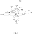
FIG. 1 is a front view illustrating an apparatus for manufacturing an electrode assembly according to an embodiment of the present invention, andFIG. 2 is a plan view illustrating the apparatus for manufacturing the electrode assembly according to an embodiment of the present invention. - Referring to
FIGS. 1 and2 , anapparatus 100 for manufacturing an electrode assembly according to an embodiment of the present invention comprises afirst roller 110 and asecond roller 120 that press astack 10 ofelectrodes 11 and aseparator 12, which are alternately stacked, to combine theelectrodes 11 and theseparator 12 with each other, a firstelastic part 140 provided along an outer circumferential surface of thefirst roller 110, and a firstdeformation prevention roller 150 that prevents the outer circumferential surface of the firstelastic part 140 from being deformed. - Also, the
apparatus 100 for manufacturing the electrode assembly according to an embodiment of the present invention may further comprise a first heater (not shown) that heats thefirst roller 110. - In more detail, the
apparatus 100 for manufacturing the electrode assembly according to an embodiment of the present invention is an apparatus for manufacturing an electrode assembly by pressing thestack 10 of the electrodes and theseparator 12 and combining the electrodes and theseparator 12 with each other. - Here, the electrode assembly may be a power generation element that is chargeable and dischargeable and be accommodated in a battery case to manufacture a secondary battery.
- The
electrode 11 may comprise a positive electrode and a negative electrode. Also, each of the separator separates a positive electrode and a negative electrode from each other to electrically insulate the positive electrode and the negative electrode from each other. - The positive electrode may comprise a positive electrode collector and a positive electrode active material applied to the positive electrode collector. For example, the positive electrode collector may be provided as foil made of an aluminum material, and the positive electrode active material may be made of lithium manganese oxide, lithium cobalt oxide, lithium nickel oxide, lithium iron phosphate, or a compound or mixture thereof containing at least one or more of the above-described materials.
- The negative electrode may comprise a negative electrode collector and a negative electrode active material applied to the negative electrode collector. For example, the negative electrode collector may be provided as foil made of a copper (Cu) or nickel (Ni) material. The negative electrode active material may comprise synthetic graphite, lithium a metal, a lithium alloy, carbon, petroleum coke, activated carbon, graphite, a silicon compound, a tin compound, a titanium compound, or an alloy thereof. Here, the negative electrode active material may further comprise, for example, non-graphite-based SiO (silica) or SiC (silicon carbide).
- The separator may be made of an insulation material, and the positive electrode, the separator, and the negative electrode may be alternately stacked. The
separator 12 may be, for example, a multi-layered film produced by microporous polyethylene, polypropylene, or a combination thereof or a polymer film for solid polymer electrolytes or gel-type polymer electrolytes such as polyvinylidene fluoride, polyethylene oxide, polyacrylonitrile, or polyvinylidene fluoride hexafluoropropylene copolymers. - The
first roller 110 and thesecond roller 120 may press both sides of thestack 10 of theelectrodes 11 and theseparator 12, which are alternately stacked, to combine theelectrodes 11 and theseparator 12 with each other. - Also, each of the
first roller 110 and thesecond roller 120 may be made of steel. Also, thefirst roller 110 and thesecond roller 120 may be formed in, for example, a cylindrical shape to rotate about a central axis thereof. Here, the central axes of thefirst roller 110 and thesecond roller 120 may be parallel to each other. At this time, thefirst roller 110 and thesecond roller 120 may rotate to continuously press thestack 10 that proceeds in a traveling direction G. - Also, the
first roller 110 may be disposed above thestack 10, and thesecond roller 120 may be disposed below thestack 10 to press top and bottom surfaces of thestack 10. - The first
elastic part 140 may be provided along the outer circumferential surface of thefirst roller 110 and may comprise an elastic material. Thus, when pressing thestack 10 through thefirst roller 110, the firstelastic part 140 made of the elastic material may be provided on the outer circumferential surface of thefirst roller 110 to prevent thestack 10 from being impacted and damaged. Particularly, a phenomenon in which an impact is applied to theelectrodes 11 and theseparator 12 at the stepped portion of thestack 10 to destroy theelectrodes 11 or the separator, resulting in a short detect may be prevented from occurring. In addition, according to the related art, when a roller made of a metal material is used, a side portion of anelectrode tab 11a, on which the stepped portion is formed, may not be pressed. However, according to the present invention, the side portion of theelectrode tab 11a may be pressed by the firstelastic part 140 made of the elastic material to improve sealing quality. - Also, the first
elastic part 140 may be formed in a cylindrical shape. - Furthermore, the first
elastic part 140 may be made of, for example, a rubber material. - The first
deformation prevention roller 150 may be provided to be in contact with the outer circumferential surface of the firstelastic part 140 so as to prevent the outer circumferential surface of the firstelastic part 140 from being deformed. - Here, the first
deformation prevention roller 150 may press the outer circumferential surface of the firstelastic part 140 so that the stepped portion is not formed on the outer circumferential surface of the firstelastic part 140. - As a result, when the first
elastic part 140 presses the end of thestack 10 through thefirst roller 110, if a deformed shape such as the stepped portion corresponding to the end of thestack 10 is formed at the firstelastic part 140 made of the elastic material, the firstdeformation prevention roller 150 may press the outer circumferential surface of the firstelastic part 140 to spread a portion at which the stepped portion occurs to form a pressing surface on which the outer circumferential surface of theelastic part 140 is more uniform. Thus, when thestack 10 is pressed through the firstelastic part 140 on which the even pressing surface is formed to seal theelectrodes 11 and theseparator 12 and combine theelectrodes 11 and theseparator 12 with each other, the sealing quality may be improved. - The first
deformation prevention roller 150 may be made of, for example, a steel material. -
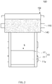
FIG. 3 is a perspective see-through view illustrating an example of a first heater which is mounted on a first roller of an apparatus for manufacturing an electrode assembly according to another embodiment of the present invention. Afirst heater 170 may be provided on afirst roller 110 to heat thefirst roller 110, thereby heating astack 10 through the heatedfirst roller 110. - Here, the
first heater 170 may comprise, for example, aheating wire 171 provided inside thefirst roller 110. At this time, when electricity flows through theheating wire 171, thefirst roller 110 may be heated by resistance heat. Also, thefirst heater 170 may further comprise aheater rod 172 in which theheating wire 171 is accommodated therein. Here, theheating wire 171 may be wound in theheater rod 172 and mounted inside thefirst roller 110. - Hereinafter, an apparatus for manufacturing an electrode assembly according to another embodiment of the present invention will be described.
-
FIG. 4 is a front view illustrating the apparatus for manufacturing the electrode assembly according to another embodiment of the present invention, andFIG. 5 is a bottom view illustrating the apparatus for manufacturing the electrode assembly according to another embodiment of the present invention. - Referring to
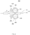
FIGS. 1 and2 , anapparatus 200 for manufacturing an electrode assembly according to another embodiment of the present invention comprises afirst roller 110 and asecond roller 120 that press astack 10 ofelectrodes 11 and aseparator 12, which are alternately stacked, to combine theelectrodes 11 and theseparator 12 with each other, a firstelastic part 140 provided along an outer circumferential surface of thefirst roller 110, a firstdeformation prevention part 150 that prevents the outer circumferential surface of the firstelastic part 140 from being deformed, a secondelastic part 240 provided along an outer circumferential surface of thesecond roller 120, and a seconddeformation prevention roller 260 that prevents the outer circumferential surface of the secondelastic part 240 from being deformed. Also, theapparatus 200 for manufacturing the electrode assembly according to another embodiment of the present invention may further comprise a first heater that heats thefirst roller 110 and a second heater (not shown) that heats thesecond roller 120. - The
apparatus 200 for manufacturing the electrode assembly according to another embodiment of the present invention is different from the apparatus for manufacturing the electrode assembly according to the foregoing embodiment of the present invention in that the secondelastic part 240 and the seconddeformation prevention roller 260 are further provided. Thus, in theapparatus 200 for manufacturing the electrode assembly according to another embodiment of the present invention, contents duplicated with those of the apparatus for manufacturing the electrode assembly according to the foregoing embodiment and the apparatus for manufacturing the electrode assembly according to another embodiment will be omitted or briefly described, and also, only differences therebetween will be described. - In more detail, the
first roller 110 and thesecond roller 120 may press both sides of thestack 10 of theelectrodes 11 and theseparator 12, which are alternately stacked, to combine theelectrodes 11 and theseparator 12 with each other. Also, each of thefirst roller 110 and thesecond roller 120 may be made of steel. Also, thefirst roller 110 may be disposed above thestack 10, and thesecond roller 120 may be disposed below thestack 10 to press top and bottom surfaces of thestack 10. - The first
elastic part 140 may be provided along the outer circumferential surface of thefirst roller 110 and may comprise an elastic material. Here, the firstelastic part 140 may be formed in a cylindrical shape. At this time, the firstelastic part 140 may be made of, for example, a rubber material. - The second
elastic part 240 may be provided along the outer circumferential surface of thesecond roller 120 and may comprise an elastic material. Here, the secondelastic part 240 may be formed in a cylindrical shape. At this time, the secondelastic part 240 may be made of, for example, a rubber material. - Therefore, when pressing the
stack 10 through thefirst roller 110 and thesecond roller 120, the firstelastic part 140 and the secondelastic part 240 are respectively provided on the outer circumferential surfaces of thefirst roller 110 and thesecond roller 120 to effectively prevent upper and lower portion of thestack 10 from being impacted and damaged. - The first
deformation prevention roller 150 may be provided to be in contact with the outer circumferential surface of the firstelastic part 140 so as to prevent the outer circumferential surface of the firstelastic part 140 from being deformed. Also, the firstdeformation prevention roller 150 may press the outer circumferential surface of the firstelastic part 140 so that the stepped portion is not formed on the outer circumferential surface of the firstelastic part 140. Here, the firstdeformation prevention roller 150 may be made of, for example, a steel material. - The second
deformation prevention roller 260 may be provided to be in contact with the outer circumferential surface of the secondelastic part 240 so as to prevent the outer circumferential surface of the secondelastic part 240 from being deformed. Also, the seconddeformation prevention roller 260 may press the outer circumferential surface of the secondelastic part 240 so that the stepped portion is not formed on the outer circumferential surface of the secondelastic part 240. Here, the seconddeformation prevention roller 260 may be made of, for example, a steel material. - Therefore, when the first
elastic part 140 presses the end of thestack 10 through thefirst roller 110 and thesecond roller 120, if a deformed shape such as the stepped portion corresponding to the end of thestack 10 is formed at the firstelastic part 140 and the secondelastic part 240, each of which is made of the elastic material, the firstdeformation prevention roller 150 and the seconddeformation prevention roller 260 may press the outer circumferential surface of the firstelastic part 140 and the secondelastic part 240 to spread a portion at which the stepped portion occurs to form a pressing surface on which each of the outer circumferential surfaces of theelastic part 140 and the secondelastic part 240 is more uniform. As a result, the upper and lower portions of thestack 10 may be pressed to the firstelastic part 140 and the secondelastic part 240, on which the even pressing surfaces are formed, respectively, through thefirst roller 110 and thesecond roller 120 to seal theelectrodes 11 and theseparator 12 so as to combine theelectrodes 11 and theseparator 12 with each other, thereby significantly improving the sealing quality. -
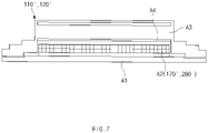
FIG. 6 is a perspective see-through view illustrating an example of first and second heaters which are respectively mounted on first and second rollers of the apparatus for manufacturing the electrode assembly according to another embodiment of the present invention, andFIG. 7 is a cross-sectional view illustrating another example of a main part of the first and second heaters, which are respectively mounted on rollers of the apparatus for manufacturing the electrode assembly according to another embodiment of the present invention. - Referring to
FIGS. 4 and6 , afirst heater 170 may be provided on thefirst roller 110 to heat thefirst roller 110. Thus, heat may be applied to thestack 10 through the heatedfirst roller 110. - A
second heater 280 may be provided on thesecond roller 120 to heat thesecond roller 120. Thus, heat may be applied to thestack 10 through the heatedsecond roller 120. - Here, the
first heater 170 and thesecond heater 280 may comprise, for example,heating wires 171 and 181 provided inside thefirst roller 110 and thesecond roller 120, respectively. At this time, when electricity flows through theheating wires 171 and 181, thefirst roller 110 and thesecond roller 120 may be heated by resistance heat. Also, thefirst heater 170 and thesecond heater 280 may further compriseheater rods heating wires heating wires heater rods first roller 110 and thesecond roller 120, respectively. - Referring to
FIGS. 4 and7 , each of a first heater 170' and a second heater 280' may be provided as an induction heating heater as another example. At this time, each of the first roll 110' and the second roller 120' may comprise a shaft A1 provided at a center thereof, an induction coil A2 wound around an outer circumferential surface of the shaft A1, and an outer cylinder A3 provided on an outer circumferential surface thereof. Here, when power is supplied to the induction coil A3, a magnetic flux crossing the outer cylinder A3 of the first roller 110' and the second roller 120' is generated, and the magnetic flux generates an eddy current in the outer cylinder A3 to generate a current flow such as an equivalent circuit, thereby heating the outer cylinder A3. At this time, heating of an initial heating portion A4 in the outer cylinder A3 starts to heat the entire outer cylinder A3. Therefore, the first roller 110' and the second roller 120' are heated in the induction heating manner, and thus, the inside and outside of the whole rollers may be heated simultaneously to maintain a temperature deviation within a temperature of 1°C. Also, a heating time (about 15 minutes) is fast, and there is no over-heating when stopped. - While the present invention has been particularly shown and described with reference to exemplary embodiments thereof, it is to be understood that the scope of the present invention is not limited to the apparatus for manufacturing the electrode assembly according to the present invention. It will be understood by those of ordinary skill in the art that various changes in form and details may be made therein without departing from the spirit and scope of the present invention.
- Furthermore, the scope of protection of the present invention will be clarified by the appended claims.
-
- 10: Stack
- 11: Electrode
- 11a: Electrode tab
- 12: Separator
- 100, 200: Apparatus for manufacturing electrode assembly
- 110: First roller
- 120: Second roller
- 140: First elastic part
- 150: First deformation prevention roller
- 260: Second deformation prevention roller
- 240: Second elastic part
- G: Traveling direction
Claims (12)
- An apparatus for manufacturing an electrode assembly, the apparatus comprising:a first roller and a second roller, which press both sides of a stack, in which electrodes and a separator are alternately stacked;a first elastic part provided along an outer circumferential surface of the first roller and comprising an elastic material; anda first deformation prevention roller provided to be in contact with an outer circumferential surface of the first elastic part so as to prevent the outer circumferential surface of the first elastic part from being deformed.
- The apparatus of claim 1, wherein the first deformation prevention roller presses the outer circumferential surface of the first elastic part so that a stepped portion is not formed on the outer circumferential surface of the first elastic part.
- The apparatus of claim 1, wherein the first elastic part is formed in a cylindrical shape.
- The apparatus of claim 1, wherein the first elastic part is made of a rubber material.
- The apparatus of claim 1, wherein the second roller is made of a steel material.
- The apparatus of claim 3, wherein the first roller is disposed above the stack, and the second roller is disposed below the stack to respectively press top and bottom surfaces of the stack.
- The apparatus of claim 1, wherein the first deformation prevention roller is made of a steel material.
- The apparatus of claim 1, further comprising a first heater provided in the first roller to heat the first roller.
- The apparatus of claim 1, further comprising a second elastic part provided along an outer circumferential surface of the second roller and comprising an elastic material.
- The apparatus of claim 9, further comprising a second deformation prevention roller disposed to be in contact with a portion facing the outer circumferential surface of the second elastic part so as to prevent a stepped portion from being formed on the outer circumferential surface of the second elastic part.
- An electrode assembly manufactured through the apparatus for manufacturing the electrode assembly of any one of claims 1 to 10.
- A secondary battery comprising the electrode assembly manufactured through the apparatus for manufacturing the electrode assembly of any one of claims 1 to 10.
Applications Claiming Priority (2)
| Application Number | Priority Date | Filing Date | Title |
|---|---|---|---|
| KR1020190166055A KR102675004B1 (en) | 2019-12-12 | 2019-12-12 | Electrode assembly manufacturing device, electrode assembly manufactured from thereof and rechargeable battery |
| PCT/KR2020/017823 WO2021118197A1 (en) | 2019-12-12 | 2020-12-08 | Electrode assembly manufacturing device, electrode assembly manufactured thereby, and secondary battery |
Publications (2)
| Publication Number | Publication Date |
|---|---|
| EP4057403A1 true EP4057403A1 (en) | 2022-09-14 |
| EP4057403A4 EP4057403A4 (en) | 2024-02-07 |
Family
ID=76330163
Family Applications (1)
| Application Number | Title | Priority Date | Filing Date |
|---|---|---|---|
| EP20898163.9A Pending EP4057403A4 (en) | 2019-12-12 | 2020-12-08 | DEVICE FOR PRODUCING AN ELECTRODE ARRANGEMENT, ELECTRODE ARRANGEMENT PRODUCED THEREFROM AND SECONDARY BATTERY |
Country Status (5)
| Country | Link |
|---|---|
| US (1) | US12580216B2 (en) |
| EP (1) | EP4057403A4 (en) |
| KR (1) | KR102675004B1 (en) |
| CN (1) | CN114762159A (en) |
| WO (1) | WO2021118197A1 (en) |
Cited By (1)
| Publication number | Priority date | Publication date | Assignee | Title |
|---|---|---|---|---|
| DE102022128222A1 (en) | 2022-10-25 | 2024-04-25 | Körber Technologies Gmbh | Laminating device for laminating multi-layer continuous webs for the production of energy cells |
Families Citing this family (3)
| Publication number | Priority date | Publication date | Assignee | Title |
|---|---|---|---|---|
| US20240128490A1 (en) * | 2021-09-16 | 2024-04-18 | Lg Energy Solution, Ltd. | Apparatus For Manufacturing Secondary Battery And Method For Manufacturing Secondary Battery Using The Same |
| CN115838091A (en) * | 2021-09-18 | 2023-03-24 | 宁德时代新能源科技股份有限公司 | roller assembly |
| KR102839132B1 (en) * | 2024-03-26 | 2025-07-29 | 한국에너지기술연구원 | Method for manufacturing lithium secondary battery electrode and manufacturing device using the same |
Family Cites Families (29)
| Publication number | Priority date | Publication date | Assignee | Title |
|---|---|---|---|---|
| JPH1050300A (en) * | 1996-07-30 | 1998-02-20 | Yamauchi Corp | Press roll for manufacturing thin electrode, press device for manufacturing thin electrode using the roll, and manufacture of thin electrode |
| JPH10228897A (en) * | 1997-02-13 | 1998-08-25 | Matsushita Electric Ind Co Ltd | Method and apparatus for manufacturing battery electrode |
| JP3460933B2 (en) | 1997-08-21 | 2003-10-27 | 東芝電池株式会社 | Electrode element for polymer battery and method for producing the same |
| JPH11176473A (en) | 1997-12-10 | 1999-07-02 | Toshiba Battery Co Ltd | Device for manufacturing electrode element for polymer battery |
| TW496006B (en) | 1999-09-22 | 2002-07-21 | Nisshin Spinning | Electrode structure, and rolling machine |
| JP4465790B2 (en) | 2000-03-30 | 2010-05-19 | ソニー株式会社 | Battery manufacturing method |
| JP3793869B2 (en) | 2000-06-12 | 2006-07-05 | グンゼ株式会社 | Surface smoothness fluorine resin tube and pressure roller |
| EP1542815B8 (en) * | 2002-09-18 | 2009-02-18 | Bathium Canada Inc. | Lamination process and apparatus for alkali metals or alloys thereof |
| JP4044060B2 (en) | 2003-12-09 | 2008-02-06 | シャープ株式会社 | Fixing device cleaning device |
| WO2006073123A1 (en) | 2005-01-06 | 2006-07-13 | Matsushita Electric Industrial Co., Ltd. | Nickel hydrogen storage battery and production method for its cathode |
| JP2008218134A (en) | 2007-03-02 | 2008-09-18 | Matsushita Electric Ind Co Ltd | Electrode group manufacturing equipment |
| JP2009181832A (en) | 2008-01-31 | 2009-08-13 | Panasonic Corp | Non-aqueous secondary battery electrode assembly manufacturing equipment |
| CN102569732B (en) | 2012-03-16 | 2014-07-02 | 天津力神电池股份有限公司 | Method for automatically repairing extreme differences of rolling rollers of battery pole plate |
| KR101528001B1 (en) | 2012-06-22 | 2015-06-10 | 주식회사 엘지화학 | Electrode assembly, manufacture thereof, and secondary batteries including same |
| KR101532730B1 (en) * | 2013-01-16 | 2015-06-30 | 주식회사 엘지화학 | Manufacturing apparatus for electrode assembly |
| KR101480137B1 (en) | 2013-04-01 | 2015-01-07 | (주)피엔티 | Thickness control apparatus for sheet coating |
| JP6127998B2 (en) * | 2014-01-31 | 2017-05-17 | 株式会社豊田自動織機 | Press machine |
| CN105082524B (en) | 2015-08-10 | 2017-07-18 | 苏州市创怡盛实业有限公司 | The roller that roller surface processing method and surface are modified |
| JP6027701B1 (en) * | 2016-05-20 | 2016-11-16 | 大野ロール株式会社 | Roll press machine with wrinkle prevention device and roll press method |
| JP6870233B2 (en) * | 2016-07-29 | 2021-05-12 | 株式会社豊田自動織機 | Electrode manufacturing equipment |
| JP2018206633A (en) | 2017-06-06 | 2018-12-27 | 株式会社豊田自動織機 | Electrode inspection method |
| CN107225069A (en) | 2017-06-09 | 2017-10-03 | 中山松德新材料装备有限公司 | A kind of novel coating machine composite press roller mechanism |
| KR102734489B1 (en) | 2017-11-15 | 2024-11-27 | 주식회사 엘지에너지솔루션 | Rolling Apparatus And Rolling Method For Secondary Battery |
| KR102674095B1 (en) | 2017-11-22 | 2024-06-12 | 주식회사 엘지에너지솔루션 | Electrode Rolling Device and Producing Facility of Electrode Assembly Including the Same |
| KR102287768B1 (en) | 2018-01-29 | 2021-08-10 | 주식회사 엘지에너지솔루션 | Electrode assembly manufacturing method and rechargeable battery manufacturing method |
| KR102446279B1 (en) | 2018-02-13 | 2022-09-22 | 주식회사 엘지에너지솔루션 | Electrode assembly manufacturing method and secondary battery manufacturing method |
| JP7060196B2 (en) | 2018-03-19 | 2022-04-26 | 信越ポリマー株式会社 | Fixing / pressurizing roller, fixing device and image forming device |
| KR102187241B1 (en) | 2018-05-30 | 2020-12-07 | (주)피엔티 | Apparatus for pressing electrode of secondary battery |
| JP7114022B2 (en) | 2018-06-06 | 2022-08-08 | 住友ゴム工業株式会社 | Strip rubber sticking method and strip rubber sticking device |
-
2019
- 2019-12-12 KR KR1020190166055A patent/KR102675004B1/en active Active
-
2020
- 2020-12-08 CN CN202080082304.0A patent/CN114762159A/en active Pending
- 2020-12-08 US US17/783,683 patent/US12580216B2/en active Active
- 2020-12-08 EP EP20898163.9A patent/EP4057403A4/en active Pending
- 2020-12-08 WO PCT/KR2020/017823 patent/WO2021118197A1/en not_active Ceased
Cited By (2)
| Publication number | Priority date | Publication date | Assignee | Title |
|---|---|---|---|---|
| DE102022128222A1 (en) | 2022-10-25 | 2024-04-25 | Körber Technologies Gmbh | Laminating device for laminating multi-layer continuous webs for the production of energy cells |
| WO2024088826A1 (en) * | 2022-10-25 | 2024-05-02 | Körber Technologies Gmbh | Laminating apparatus for laminating multilayer endless webs for producing energy cells |
Also Published As
| Publication number | Publication date |
|---|---|
| KR20210074907A (en) | 2021-06-22 |
| EP4057403A4 (en) | 2024-02-07 |
| US20230105865A1 (en) | 2023-04-06 |
| KR102675004B1 (en) | 2024-06-14 |
| CN114762159A (en) | 2022-07-15 |
| US12580216B2 (en) | 2026-03-17 |
| WO2021118197A1 (en) | 2021-06-17 |
Similar Documents
| Publication | Publication Date | Title |
|---|---|---|
| EP3905417A1 (en) | Method for manufacturing electrode assembly, and electrode and secondary battery manufactured thereby | |
| KR102480958B1 (en) | Rechargeable battery | |
| US12580216B2 (en) | Apparatus for manufacturing electrode assembly, electrode assembly manufactured therethrough, and secondary battery | |
| EP3537497B1 (en) | Secondary battery, manufacturing method therefor, and pressing block for manufacturing secondary battery | |
| JP2025087870A (en) | Cell with Tabless Structure Electrode | |
| US20240055741A1 (en) | Electrode assembly and secondary battery comprising the same | |
| CN209312928U (en) | Electrode assembly | |
| EP4220796B1 (en) | Secondary battery and method for manufacturing the same, and pressing block for manufacturing secondary battery | |
| US20240313266A1 (en) | Secondary Battery | |
| CN103098285A (en) | Secondary lithium battery with multi-directional lead-tab structure | |
| JP7372006B2 (en) | Secondary batteries and devices containing them | |
| KR20230046461A (en) | Electrode assembly manufacturing method and manufacturing device | |
| US11355818B2 (en) | Apparatus and method for manufacturing electrode assembly | |
| JP2024521380A (en) | Rivet structure for electrode terminal, and battery cell, battery pack, and automobile including the same | |
| KR20210140997A (en) | Electrode assembly | |
| EP4164028B1 (en) | Electrode assembly and secondary battery comprising the same | |
| CN114556648B (en) | Method for manufacturing electrode assembly and electrode assembly manufactured by the method | |
| EP4579867A1 (en) | Electrode assembly and secondary battery including same | |
| KR20210012457A (en) | Rechargeable battery manufacturing method, rechargeable battery manufactured from thereof | |
| KR20190075381A (en) | Electrode assembly and rechargeable battery comprising the same |
Legal Events
| Date | Code | Title | Description |
|---|---|---|---|
| STAA | Information on the status of an ep patent application or granted ep patent |
Free format text: STATUS: THE INTERNATIONAL PUBLICATION HAS BEEN MADE |
|
| PUAI | Public reference made under article 153(3) epc to a published international application that has entered the european phase |
Free format text: ORIGINAL CODE: 0009012 |
|
| STAA | Information on the status of an ep patent application or granted ep patent |
Free format text: STATUS: REQUEST FOR EXAMINATION WAS MADE |
|
| 17P | Request for examination filed |
Effective date: 20220609 |
|
| AK | Designated contracting states |
Kind code of ref document: A1 Designated state(s): AL AT BE BG CH CY CZ DE DK EE ES FI FR GB GR HR HU IE IS IT LI LT LU LV MC MK MT NL NO PL PT RO RS SE SI SK SM TR |
|
| DAV | Request for validation of the european patent (deleted) | ||
| DAX | Request for extension of the european patent (deleted) | ||
| A4 | Supplementary search report drawn up and despatched |
Effective date: 20240109 |
|
| RIC1 | Information provided on ipc code assigned before grant |
Ipc: H01M 4/04 20060101ALI20240103BHEP Ipc: H01M 10/0585 20100101ALI20240103BHEP Ipc: H01M 10/04 20060101AFI20240103BHEP |