EP4057392A1 - Negative electrode material and preparation method therefor, battery, and terminal - Google Patents
Negative electrode material and preparation method therefor, battery, and terminal Download PDFInfo
- Publication number
- EP4057392A1 EP4057392A1 EP20892425.8A EP20892425A EP4057392A1 EP 4057392 A1 EP4057392 A1 EP 4057392A1 EP 20892425 A EP20892425 A EP 20892425A EP 4057392 A1 EP4057392 A1 EP 4057392A1
- Authority
- EP
- European Patent Office
- Prior art keywords
- negative electrode
- carbon
- doped
- electrode material
- doped carbon
- Prior art date
- Legal status (The legal status is an assumption and is not a legal conclusion. Google has not performed a legal analysis and makes no representation as to the accuracy of the status listed.)
- Pending
Links
- 239000007773 negative electrode material Substances 0.000 title claims abstract description 109
- 238000002360 preparation method Methods 0.000 title 1
- OKTJSMMVPCPJKN-UHFFFAOYSA-N Carbon Chemical compound [C] OKTJSMMVPCPJKN-UHFFFAOYSA-N 0.000 claims abstract description 158
- 239000003575 carbonaceous material Substances 0.000 claims abstract description 125
- 229910052799 carbon Inorganic materials 0.000 claims abstract description 113
- 239000000126 substance Substances 0.000 claims abstract description 47
- 229910052698 phosphorus Inorganic materials 0.000 claims abstract description 42
- 239000011159 matrix material Substances 0.000 claims abstract description 41
- 229910052760 oxygen Inorganic materials 0.000 claims abstract description 37
- 238000004519 manufacturing process Methods 0.000 claims abstract description 26
- 229910052757 nitrogen Inorganic materials 0.000 claims abstract description 25
- 229910052796 boron Inorganic materials 0.000 claims abstract description 14
- 229910052731 fluorine Inorganic materials 0.000 claims abstract description 14
- 229910052717 sulfur Inorganic materials 0.000 claims abstract description 14
- 238000000034 method Methods 0.000 claims description 62
- 239000002243 precursor Substances 0.000 claims description 39
- 239000002245 particle Substances 0.000 claims description 36
- 239000000463 material Substances 0.000 claims description 33
- 239000011246 composite particle Substances 0.000 claims description 32
- 238000005245 sintering Methods 0.000 claims description 29
- 239000011247 coating layer Substances 0.000 claims description 28
- 239000010410 layer Substances 0.000 claims description 27
- 238000012545 processing Methods 0.000 claims description 26
- 238000003763 carbonization Methods 0.000 claims description 20
- 238000002156 mixing Methods 0.000 claims description 18
- 229910021385 hard carbon Inorganic materials 0.000 claims description 17
- 229910001416 lithium ion Inorganic materials 0.000 claims description 17
- HBBGRARXTFLTSG-UHFFFAOYSA-N Lithium ion Chemical compound [Li+] HBBGRARXTFLTSG-UHFFFAOYSA-N 0.000 claims description 16
- 239000011241 protective layer Substances 0.000 claims description 15
- XLYOFNOQVPJJNP-UHFFFAOYSA-N water Substances O XLYOFNOQVPJJNP-UHFFFAOYSA-N 0.000 claims description 15
- NBIIXXVUZAFLBC-UHFFFAOYSA-N Phosphoric acid Chemical compound OP(O)(O)=O NBIIXXVUZAFLBC-UHFFFAOYSA-N 0.000 claims description 14
- ROOXNKNUYICQNP-UHFFFAOYSA-N ammonium persulfate Chemical compound [NH4+].[NH4+].[O-]S(=O)(=O)OOS([O-])(=O)=O ROOXNKNUYICQNP-UHFFFAOYSA-N 0.000 claims description 14
- 238000009656 pre-carbonization Methods 0.000 claims description 12
- 229910021383 artificial graphite Inorganic materials 0.000 claims description 11
- 239000003792 electrolyte Substances 0.000 claims description 11
- MHAJPDPJQMAIIY-UHFFFAOYSA-N Hydrogen peroxide Chemical compound OO MHAJPDPJQMAIIY-UHFFFAOYSA-N 0.000 claims description 10
- 150000001721 carbon Chemical class 0.000 claims description 10
- 229920001940 conductive polymer Polymers 0.000 claims description 10
- 239000011164 primary particle Substances 0.000 claims description 10
- 239000011163 secondary particle Substances 0.000 claims description 10
- 229910001415 sodium ion Inorganic materials 0.000 claims description 10
- FKNQFGJONOIPTF-UHFFFAOYSA-N Sodium cation Chemical compound [Na+] FKNQFGJONOIPTF-UHFFFAOYSA-N 0.000 claims description 9
- XSQUKJJJFZCRTK-UHFFFAOYSA-N Urea Chemical compound NC(N)=O XSQUKJJJFZCRTK-UHFFFAOYSA-N 0.000 claims description 9
- KRKNYBCHXYNGOX-UHFFFAOYSA-N citric acid Chemical compound OC(=O)CC(O)(C(O)=O)CC(O)=O KRKNYBCHXYNGOX-UHFFFAOYSA-N 0.000 claims description 9
- RAXXELZNTBOGNW-UHFFFAOYSA-N imidazole Natural products C1=CNC=N1 RAXXELZNTBOGNW-UHFFFAOYSA-N 0.000 claims description 9
- 229910000147 aluminium phosphate Inorganic materials 0.000 claims description 7
- 229910001870 ammonium persulfate Inorganic materials 0.000 claims description 7
- 229910052732 germanium Inorganic materials 0.000 claims description 7
- GNPVGFCGXDBREM-UHFFFAOYSA-N germanium atom Chemical compound [Ge] GNPVGFCGXDBREM-UHFFFAOYSA-N 0.000 claims description 7
- JUJWROOIHBZHMG-UHFFFAOYSA-N Pyridine Chemical compound C1=CC=NC=C1 JUJWROOIHBZHMG-UHFFFAOYSA-N 0.000 claims description 6
- KAESVJOAVNADME-UHFFFAOYSA-N Pyrrole Chemical compound C=1C=CNC=1 KAESVJOAVNADME-UHFFFAOYSA-N 0.000 claims description 6
- YTPLMLYBLZKORZ-UHFFFAOYSA-N Thiophene Chemical compound C=1C=CSC=1 YTPLMLYBLZKORZ-UHFFFAOYSA-N 0.000 claims description 6
- 229910021393 carbon nanotube Inorganic materials 0.000 claims description 6
- 239000002041 carbon nanotube Substances 0.000 claims description 6
- 238000006243 chemical reaction Methods 0.000 claims description 6
- JKWMSGQKBLHBQQ-UHFFFAOYSA-N diboron trioxide Chemical compound O=BOB=O JKWMSGQKBLHBQQ-UHFFFAOYSA-N 0.000 claims description 6
- PQXKHYXIUOZZFA-UHFFFAOYSA-M lithium fluoride Chemical compound [Li+].[F-] PQXKHYXIUOZZFA-UHFFFAOYSA-M 0.000 claims description 6
- 238000002844 melting Methods 0.000 claims description 6
- 230000008018 melting Effects 0.000 claims description 6
- 238000007500 overflow downdraw method Methods 0.000 claims description 6
- HHVIBTZHLRERCL-UHFFFAOYSA-N sulfonyldimethane Chemical compound CS(C)(=O)=O HHVIBTZHLRERCL-UHFFFAOYSA-N 0.000 claims description 6
- UMGDCJDMYOKAJW-UHFFFAOYSA-N thiourea Chemical compound NC(N)=S UMGDCJDMYOKAJW-UHFFFAOYSA-N 0.000 claims description 6
- JLVVSXFLKOJNIY-UHFFFAOYSA-N Magnesium ion Chemical compound [Mg+2] JLVVSXFLKOJNIY-UHFFFAOYSA-N 0.000 claims description 5
- PTFCDOFLOPIGGS-UHFFFAOYSA-N Zinc dication Chemical compound [Zn+2] PTFCDOFLOPIGGS-UHFFFAOYSA-N 0.000 claims description 5
- 239000006230 acetylene black Substances 0.000 claims description 5
- 238000000498 ball milling Methods 0.000 claims description 5
- 229910021389 graphene Inorganic materials 0.000 claims description 5
- 238000001027 hydrothermal synthesis Methods 0.000 claims description 5
- 229910001425 magnesium ion Inorganic materials 0.000 claims description 5
- 238000001755 magnetron sputter deposition Methods 0.000 claims description 5
- 229910021382 natural graphite Inorganic materials 0.000 claims description 5
- 229920001467 poly(styrenesulfonates) Polymers 0.000 claims description 5
- 229910021384 soft carbon Inorganic materials 0.000 claims description 5
- 238000003980 solgel method Methods 0.000 claims description 5
- 238000004729 solvothermal method Methods 0.000 claims description 5
- 238000007740 vapor deposition Methods 0.000 claims description 5
- CBTAIOOTRCAMBD-UHFFFAOYSA-N 2-ethoxy-2,4,4,6,6-pentafluoro-1,3,5-triaza-2$l^{5},4$l^{5},6$l^{5}-triphosphacyclohexa-1,3,5-triene Chemical compound CCOP1(F)=NP(F)(F)=NP(F)(F)=N1 CBTAIOOTRCAMBD-UHFFFAOYSA-N 0.000 claims description 4
- LJGHYPLBDBRCRZ-UHFFFAOYSA-N 3-(3-aminophenyl)sulfonylaniline Chemical compound NC1=CC=CC(S(=O)(=O)C=2C=C(N)C=CC=2)=C1 LJGHYPLBDBRCRZ-UHFFFAOYSA-N 0.000 claims description 4
- 229920000049 Carbon (fiber) Polymers 0.000 claims description 4
- LZZYPRNAOMGNLH-UHFFFAOYSA-M Cetrimonium bromide Chemical compound [Br-].CCCCCCCCCCCCCCCC[N+](C)(C)C LZZYPRNAOMGNLH-UHFFFAOYSA-M 0.000 claims description 4
- 229920000877 Melamine resin Polymers 0.000 claims description 4
- NPYPAHLBTDXSSS-UHFFFAOYSA-N Potassium ion Chemical compound [K+] NPYPAHLBTDXSSS-UHFFFAOYSA-N 0.000 claims description 4
- JDZCKJOXGCMJGS-UHFFFAOYSA-N [Li].[S] Chemical compound [Li].[S] JDZCKJOXGCMJGS-UHFFFAOYSA-N 0.000 claims description 4
- 239000004917 carbon fiber Substances 0.000 claims description 4
- 239000011248 coating agent Substances 0.000 claims description 4
- 238000000576 coating method Methods 0.000 claims description 4
- 238000001816 cooling Methods 0.000 claims description 4
- 239000003273 ketjen black Substances 0.000 claims description 4
- JDSHMPZPIAZGSV-UHFFFAOYSA-N melamine Chemical compound NC1=NC(N)=NC(N)=N1 JDSHMPZPIAZGSV-UHFFFAOYSA-N 0.000 claims description 4
- 239000002931 mesocarbon microbead Substances 0.000 claims description 4
- 150000002736 metal compounds Chemical class 0.000 claims description 4
- 229910001092 metal group alloy Inorganic materials 0.000 claims description 4
- GKTNLYAAZKKMTQ-UHFFFAOYSA-N n-[bis(dimethylamino)phosphinimyl]-n-methylmethanamine Chemical compound CN(C)P(=N)(N(C)C)N(C)C GKTNLYAAZKKMTQ-UHFFFAOYSA-N 0.000 claims description 4
- 229910001414 potassium ion Inorganic materials 0.000 claims description 4
- 229940037179 potassium ion Drugs 0.000 claims description 4
- 230000001681 protective effect Effects 0.000 claims description 4
- 239000002210 silicon-based material Substances 0.000 claims description 4
- DLYUQMMRRRQYAE-UHFFFAOYSA-N tetraphosphorus decaoxide Chemical compound O1P(O2)(=O)OP3(=O)OP1(=O)OP2(=O)O3 DLYUQMMRRRQYAE-UHFFFAOYSA-N 0.000 claims description 4
- 239000011366 tin-based material Substances 0.000 claims description 4
- IRPGOXJVTQTAAN-UHFFFAOYSA-N 2,2,3,3,3-pentafluoropropanal Chemical compound FC(F)(F)C(F)(F)C=O IRPGOXJVTQTAAN-UHFFFAOYSA-N 0.000 claims description 3
- PWKSKIMOESPYIA-UHFFFAOYSA-N 2-acetamido-3-sulfanylpropanoic acid Chemical compound CC(=O)NC(CS)C(O)=O PWKSKIMOESPYIA-UHFFFAOYSA-N 0.000 claims description 3
- KLZUFWVZNOTSEM-UHFFFAOYSA-K Aluminum fluoride Inorganic materials F[Al](F)F KLZUFWVZNOTSEM-UHFFFAOYSA-K 0.000 claims description 3
- VHUUQVKOLVNVRT-UHFFFAOYSA-N Ammonium hydroxide Chemical compound [NH4+].[OH-] VHUUQVKOLVNVRT-UHFFFAOYSA-N 0.000 claims description 3
- 229910052582 BN Inorganic materials 0.000 claims description 3
- PZNSFCLAULLKQX-UHFFFAOYSA-N Boron nitride Chemical compound N#B PZNSFCLAULLKQX-UHFFFAOYSA-N 0.000 claims description 3
- 239000005696 Diammonium phosphate Substances 0.000 claims description 3
- PIICEJLVQHRZGT-UHFFFAOYSA-N Ethylenediamine Chemical compound NCCN PIICEJLVQHRZGT-UHFFFAOYSA-N 0.000 claims description 3
- FXNMVJXZYJXPOI-UHFFFAOYSA-N FP([N]P(F)(F)=N1)N=P1(F)F Chemical compound FP([N]P(F)(F)=N1)N=P1(F)F FXNMVJXZYJXPOI-UHFFFAOYSA-N 0.000 claims description 3
- GRYLNZFGIOXLOG-UHFFFAOYSA-N Nitric acid Chemical compound O[N+]([O-])=O GRYLNZFGIOXLOG-UHFFFAOYSA-N 0.000 claims description 3
- PMZURENOXWZQFD-UHFFFAOYSA-L Sodium Sulfate Chemical compound [Na+].[Na+].[O-]S([O-])(=O)=O PMZURENOXWZQFD-UHFFFAOYSA-L 0.000 claims description 3
- LFVGISIMTYGQHF-UHFFFAOYSA-N ammonium dihydrogen phosphate Chemical compound [NH4+].OP(O)([O-])=O LFVGISIMTYGQHF-UHFFFAOYSA-N 0.000 claims description 3
- 229910000387 ammonium dihydrogen phosphate Inorganic materials 0.000 claims description 3
- LDDQLRUQCUTJBB-UHFFFAOYSA-N ammonium fluoride Chemical compound [NH4+].[F-] LDDQLRUQCUTJBB-UHFFFAOYSA-N 0.000 claims description 3
- 235000011114 ammonium hydroxide Nutrition 0.000 claims description 3
- KGBXLFKZBHKPEV-UHFFFAOYSA-N boric acid Chemical compound OB(O)O KGBXLFKZBHKPEV-UHFFFAOYSA-N 0.000 claims description 3
- 239000004327 boric acid Substances 0.000 claims description 3
- WUKWITHWXAAZEY-UHFFFAOYSA-L calcium difluoride Chemical compound [F-].[F-].[Ca+2] WUKWITHWXAAZEY-UHFFFAOYSA-L 0.000 claims description 3
- 229910001634 calcium fluoride Inorganic materials 0.000 claims description 3
- 239000004202 carbamide Substances 0.000 claims description 3
- 235000013877 carbamide Nutrition 0.000 claims description 3
- MNNHAPBLZZVQHP-UHFFFAOYSA-N diammonium hydrogen phosphate Chemical compound [NH4+].[NH4+].OP([O-])([O-])=O MNNHAPBLZZVQHP-UHFFFAOYSA-N 0.000 claims description 3
- 229910000388 diammonium phosphate Inorganic materials 0.000 claims description 3
- 235000019838 diammonium phosphate Nutrition 0.000 claims description 3
- UBIJTWDKTYCPMQ-UHFFFAOYSA-N hexachlorophosphazene Chemical compound ClP1(Cl)=NP(Cl)(Cl)=NP(Cl)(Cl)=N1 UBIJTWDKTYCPMQ-UHFFFAOYSA-N 0.000 claims description 3
- 229910001386 lithium phosphate Inorganic materials 0.000 claims description 3
- 235000019837 monoammonium phosphate Nutrition 0.000 claims description 3
- 229910017604 nitric acid Inorganic materials 0.000 claims description 3
- UMJSCPRVCHMLSP-UHFFFAOYSA-N pyridine Natural products COC1=CC=CN=C1 UMJSCPRVCHMLSP-UHFFFAOYSA-N 0.000 claims description 3
- ABTOQLMXBSRXSM-UHFFFAOYSA-N silicon tetrafluoride Chemical compound F[Si](F)(F)F ABTOQLMXBSRXSM-UHFFFAOYSA-N 0.000 claims description 3
- 229910052938 sodium sulfate Inorganic materials 0.000 claims description 3
- 235000011152 sodium sulphate Nutrition 0.000 claims description 3
- YUKQRDCYNOVPGJ-UHFFFAOYSA-N thioacetamide Chemical compound CC(N)=S YUKQRDCYNOVPGJ-UHFFFAOYSA-N 0.000 claims description 3
- DLFVBJFMPXGRIB-UHFFFAOYSA-N thioacetamide Natural products CC(N)=O DLFVBJFMPXGRIB-UHFFFAOYSA-N 0.000 claims description 3
- 229930192474 thiophene Natural products 0.000 claims description 3
- TWQULNDIKKJZPH-UHFFFAOYSA-K trilithium;phosphate Chemical compound [Li+].[Li+].[Li+].[O-]P([O-])([O-])=O TWQULNDIKKJZPH-UHFFFAOYSA-K 0.000 claims description 3
- 239000002002 slurry Substances 0.000 description 45
- 239000000306 component Substances 0.000 description 40
- 229910002804 graphite Inorganic materials 0.000 description 25
- 239000010439 graphite Substances 0.000 description 24
- 150000002500 ions Chemical class 0.000 description 23
- 230000000052 comparative effect Effects 0.000 description 19
- IJGRMHOSHXDMSA-UHFFFAOYSA-N Atomic nitrogen Chemical compound N#N IJGRMHOSHXDMSA-UHFFFAOYSA-N 0.000 description 17
- 239000000843 powder Substances 0.000 description 16
- 238000010298 pulverizing process Methods 0.000 description 16
- 239000010426 asphalt Substances 0.000 description 14
- 238000003756 stirring Methods 0.000 description 11
- 238000010586 diagram Methods 0.000 description 10
- 239000007787 solid Substances 0.000 description 10
- 230000002829 reductive effect Effects 0.000 description 9
- -1 poly(styrenesulfonate) Polymers 0.000 description 7
- 230000007547 defect Effects 0.000 description 6
- 238000006297 dehydration reaction Methods 0.000 description 6
- 230000014759 maintenance of location Effects 0.000 description 6
- OAICVXFJPJFONN-UHFFFAOYSA-N Phosphorus Chemical compound [P] OAICVXFJPJFONN-UHFFFAOYSA-N 0.000 description 5
- VYPSYNLAJGMNEJ-UHFFFAOYSA-N Silicium dioxide Chemical compound O=[Si]=O VYPSYNLAJGMNEJ-UHFFFAOYSA-N 0.000 description 5
- HMDDXIMCDZRSNE-UHFFFAOYSA-N [C].[Si] Chemical compound [C].[Si] HMDDXIMCDZRSNE-UHFFFAOYSA-N 0.000 description 5
- 125000004432 carbon atom Chemical group C* 0.000 description 5
- 239000011294 coal tar pitch Substances 0.000 description 5
- 238000009792 diffusion process Methods 0.000 description 5
- 238000007599 discharging Methods 0.000 description 5
- 239000011574 phosphorus Substances 0.000 description 5
- LIVNPJMFVYWSIS-UHFFFAOYSA-N silicon monoxide Chemical compound [Si-]#[O+] LIVNPJMFVYWSIS-UHFFFAOYSA-N 0.000 description 5
- 229910052814 silicon oxide Inorganic materials 0.000 description 5
- XKRFYHLGVUSROY-UHFFFAOYSA-N Argon Chemical compound [Ar] XKRFYHLGVUSROY-UHFFFAOYSA-N 0.000 description 4
- 229910014572 C—O—P Inorganic materials 0.000 description 4
- 239000007772 electrode material Substances 0.000 description 4
- 238000005469 granulation Methods 0.000 description 4
- 230000003179 granulation Effects 0.000 description 4
- 239000005543 nano-size silicon particle Substances 0.000 description 4
- 238000011056 performance test Methods 0.000 description 4
- 239000007774 positive electrode material Substances 0.000 description 4
- 229910052710 silicon Inorganic materials 0.000 description 4
- 239000010703 silicon Substances 0.000 description 4
- XUIMIQQOPSSXEZ-UHFFFAOYSA-N Silicon Chemical compound [Si] XUIMIQQOPSSXEZ-UHFFFAOYSA-N 0.000 description 3
- ATJFFYVFTNAWJD-UHFFFAOYSA-N Tin Chemical compound [Sn] ATJFFYVFTNAWJD-UHFFFAOYSA-N 0.000 description 3
- 238000004833 X-ray photoelectron spectroscopy Methods 0.000 description 3
- 125000004429 atom Chemical group 0.000 description 3
- QVGXLLKOCUKJST-UHFFFAOYSA-N atomic oxygen Chemical compound [O] QVGXLLKOCUKJST-UHFFFAOYSA-N 0.000 description 3
- 230000009286 beneficial effect Effects 0.000 description 3
- 239000002131 composite material Substances 0.000 description 3
- 238000009826 distribution Methods 0.000 description 3
- 230000004927 fusion Effects 0.000 description 3
- 229910052744 lithium Inorganic materials 0.000 description 3
- 239000000203 mixture Substances 0.000 description 3
- QJGQUHMNIGDVPM-UHFFFAOYSA-N nitrogen group Chemical group [N] QJGQUHMNIGDVPM-UHFFFAOYSA-N 0.000 description 3
- 239000001301 oxygen Substances 0.000 description 3
- 239000003208 petroleum Substances 0.000 description 3
- 238000003860 storage Methods 0.000 description 3
- 239000010409 thin film Substances 0.000 description 3
- UQSXHKLRYXJYBZ-UHFFFAOYSA-N Iron oxide Chemical compound [Fe]=O UQSXHKLRYXJYBZ-UHFFFAOYSA-N 0.000 description 2
- 239000002033 PVDF binder Substances 0.000 description 2
- 229920001609 Poly(3,4-ethylenedioxythiophene) Polymers 0.000 description 2
- 229920000265 Polyparaphenylene Polymers 0.000 description 2
- XLOMVQKBTHCTTD-UHFFFAOYSA-N Zinc monoxide Chemical compound [Zn]=O XLOMVQKBTHCTTD-UHFFFAOYSA-N 0.000 description 2
- HSFWRNGVRCDJHI-UHFFFAOYSA-N alpha-acetylene Natural products C#C HSFWRNGVRCDJHI-UHFFFAOYSA-N 0.000 description 2
- 229910052786 argon Inorganic materials 0.000 description 2
- 210000004027 cell Anatomy 0.000 description 2
- 150000001875 compounds Chemical class 0.000 description 2
- 239000008367 deionised water Substances 0.000 description 2
- 229910021641 deionized water Inorganic materials 0.000 description 2
- 210000001787 dendrite Anatomy 0.000 description 2
- 238000013461 design Methods 0.000 description 2
- YWEUIGNSBFLMFL-UHFFFAOYSA-N diphosphonate Chemical compound O=P(=O)OP(=O)=O YWEUIGNSBFLMFL-UHFFFAOYSA-N 0.000 description 2
- 238000002149 energy-dispersive X-ray emission spectroscopy Methods 0.000 description 2
- 238000005516 engineering process Methods 0.000 description 2
- 238000000605 extraction Methods 0.000 description 2
- 239000007770 graphite material Substances 0.000 description 2
- AMWRITDGCCNYAT-UHFFFAOYSA-L hydroxy(oxo)manganese;manganese Chemical compound [Mn].O[Mn]=O.O[Mn]=O AMWRITDGCCNYAT-UHFFFAOYSA-L 0.000 description 2
- 239000011295 pitch Substances 0.000 description 2
- 229920000553 poly(phenylenevinylene) Polymers 0.000 description 2
- 229920001197 polyacetylene Polymers 0.000 description 2
- 229920000767 polyaniline Polymers 0.000 description 2
- 229920000128 polypyrrole Polymers 0.000 description 2
- 229920000123 polythiophene Polymers 0.000 description 2
- 229920002981 polyvinylidene fluoride Polymers 0.000 description 2
- 230000008439 repair process Effects 0.000 description 2
- 239000002904 solvent Substances 0.000 description 2
- 238000010998 test method Methods 0.000 description 2
- 238000012360 testing method Methods 0.000 description 2
- 238000001291 vacuum drying Methods 0.000 description 2
- ZOXJGFHDIHLPTG-UHFFFAOYSA-N Boron Chemical compound [B] ZOXJGFHDIHLPTG-UHFFFAOYSA-N 0.000 description 1
- 229910001339 C alloy Inorganic materials 0.000 description 1
- RYGMFSIKBFXOCR-UHFFFAOYSA-N Copper Chemical compound [Cu] RYGMFSIKBFXOCR-UHFFFAOYSA-N 0.000 description 1
- QPLDLSVMHZLSFG-UHFFFAOYSA-N Copper oxide Chemical compound [Cu]=O QPLDLSVMHZLSFG-UHFFFAOYSA-N 0.000 description 1
- 239000005751 Copper oxide Substances 0.000 description 1
- MBMLMWLHJBBADN-UHFFFAOYSA-N Ferrous sulfide Chemical compound [Fe]=S MBMLMWLHJBBADN-UHFFFAOYSA-N 0.000 description 1
- YCKRFDGAMUMZLT-UHFFFAOYSA-N Fluorine atom Chemical compound [F] YCKRFDGAMUMZLT-UHFFFAOYSA-N 0.000 description 1
- 229910000927 Ge alloy Inorganic materials 0.000 description 1
- UFHFLCQGNIYNRP-UHFFFAOYSA-N Hydrogen Chemical compound [H][H] UFHFLCQGNIYNRP-UHFFFAOYSA-N 0.000 description 1
- 229910001290 LiPF6 Inorganic materials 0.000 description 1
- WHXSMMKQMYFTQS-UHFFFAOYSA-N Lithium Chemical compound [Li] WHXSMMKQMYFTQS-UHFFFAOYSA-N 0.000 description 1
- SECXISVLQFMRJM-UHFFFAOYSA-N N-Methylpyrrolidone Chemical compound CN1CCCC1=O SECXISVLQFMRJM-UHFFFAOYSA-N 0.000 description 1
- 229910019398 NaPF6 Inorganic materials 0.000 description 1
- 229910004856 P—O—P Inorganic materials 0.000 description 1
- 229910000676 Si alloy Inorganic materials 0.000 description 1
- 229910001128 Sn alloy Inorganic materials 0.000 description 1
- KEAYESYHFKHZAL-UHFFFAOYSA-N Sodium Chemical compound [Na] KEAYESYHFKHZAL-UHFFFAOYSA-N 0.000 description 1
- NINIDFKCEFEMDL-UHFFFAOYSA-N Sulfur Chemical compound [S] NINIDFKCEFEMDL-UHFFFAOYSA-N 0.000 description 1
- RTAQQCXQSZGOHL-UHFFFAOYSA-N Titanium Chemical compound [Ti] RTAQQCXQSZGOHL-UHFFFAOYSA-N 0.000 description 1
- KCFIHQSTJSCCBR-UHFFFAOYSA-N [C].[Ge] Chemical compound [C].[Ge] KCFIHQSTJSCCBR-UHFFFAOYSA-N 0.000 description 1
- JFBZPFYRPYOZCQ-UHFFFAOYSA-N [Li].[Al] Chemical compound [Li].[Al] JFBZPFYRPYOZCQ-UHFFFAOYSA-N 0.000 description 1
- ZVLDJSZFKQJMKD-UHFFFAOYSA-N [Li].[Si] Chemical compound [Li].[Si] ZVLDJSZFKQJMKD-UHFFFAOYSA-N 0.000 description 1
- YZSKZXUDGLALTQ-UHFFFAOYSA-N [Li][C] Chemical compound [Li][C] YZSKZXUDGLALTQ-UHFFFAOYSA-N 0.000 description 1
- QWJYDTCSUDMGSU-UHFFFAOYSA-N [Sn].[C] Chemical compound [Sn].[C] QWJYDTCSUDMGSU-UHFFFAOYSA-N 0.000 description 1
- 229910045601 alloy Inorganic materials 0.000 description 1
- 239000000956 alloy Substances 0.000 description 1
- 229910003481 amorphous carbon Inorganic materials 0.000 description 1
- 230000002238 attenuated effect Effects 0.000 description 1
- 230000015572 biosynthetic process Effects 0.000 description 1
- 239000003610 charcoal Substances 0.000 description 1
- 238000005253 cladding Methods 0.000 description 1
- 229910000428 cobalt oxide Inorganic materials 0.000 description 1
- IVMYJDGYRUAWML-UHFFFAOYSA-N cobalt(ii) oxide Chemical compound [Co]=O IVMYJDGYRUAWML-UHFFFAOYSA-N 0.000 description 1
- 239000011889 copper foil Substances 0.000 description 1
- 229910000431 copper oxide Inorganic materials 0.000 description 1
- 239000008358 core component Substances 0.000 description 1
- GSQKXUNYYCYYKT-UHFFFAOYSA-N cyclo-trialuminium Chemical compound [Al]1[Al]=[Al]1 GSQKXUNYYCYYKT-UHFFFAOYSA-N 0.000 description 1
- 238000011161 development Methods 0.000 description 1
- 230000000694 effects Effects 0.000 description 1
- 238000000835 electrochemical detection Methods 0.000 description 1
- 238000004880 explosion Methods 0.000 description 1
- 239000011737 fluorine Substances 0.000 description 1
- YFKPABFAJKUPTN-UHFFFAOYSA-N germanium lithium Chemical compound [Li].[Ge] YFKPABFAJKUPTN-UHFFFAOYSA-N 0.000 description 1
- YBMRDBCBODYGJE-UHFFFAOYSA-N germanium oxide Inorganic materials O=[Ge]=O YBMRDBCBODYGJE-UHFFFAOYSA-N 0.000 description 1
- 239000011307 graphite pitch Substances 0.000 description 1
- 229910003474 graphite-silicon composite material Inorganic materials 0.000 description 1
- 239000001307 helium Substances 0.000 description 1
- 229910052734 helium Inorganic materials 0.000 description 1
- SWQJXJOGLNCZEY-UHFFFAOYSA-N helium atom Chemical compound [He] SWQJXJOGLNCZEY-UHFFFAOYSA-N 0.000 description 1
- 239000001257 hydrogen Substances 0.000 description 1
- 229910052739 hydrogen Inorganic materials 0.000 description 1
- 238000009776 industrial production Methods 0.000 description 1
- 230000002427 irreversible effect Effects 0.000 description 1
- UIDWHMKSOZZDAV-UHFFFAOYSA-N lithium tin Chemical compound [Li].[Sn] UIDWHMKSOZZDAV-UHFFFAOYSA-N 0.000 description 1
- VNWKTOKETHGBQD-UHFFFAOYSA-N methane Chemical compound C VNWKTOKETHGBQD-UHFFFAOYSA-N 0.000 description 1
- 239000012046 mixed solvent Substances 0.000 description 1
- CWQXQMHSOZUFJS-UHFFFAOYSA-N molybdenum disulfide Chemical compound S=[Mo]=S CWQXQMHSOZUFJS-UHFFFAOYSA-N 0.000 description 1
- 229910000476 molybdenum oxide Inorganic materials 0.000 description 1
- 229910000480 nickel oxide Inorganic materials 0.000 description 1
- 238000005457 optimization Methods 0.000 description 1
- 230000003647 oxidation Effects 0.000 description 1
- 238000007254 oxidation reaction Methods 0.000 description 1
- PVADDRMAFCOOPC-UHFFFAOYSA-N oxogermanium Chemical compound [Ge]=O PVADDRMAFCOOPC-UHFFFAOYSA-N 0.000 description 1
- PQQKPALAQIIWST-UHFFFAOYSA-N oxomolybdenum Chemical compound [Mo]=O PQQKPALAQIIWST-UHFFFAOYSA-N 0.000 description 1
- GNRSAWUEBMWBQH-UHFFFAOYSA-N oxonickel Chemical compound [Ni]=O GNRSAWUEBMWBQH-UHFFFAOYSA-N 0.000 description 1
- 229910021426 porous silicon Inorganic materials 0.000 description 1
- 229920005989 resin Polymers 0.000 description 1
- 239000011347 resin Substances 0.000 description 1
- 230000002441 reversible effect Effects 0.000 description 1
- 238000007086 side reaction Methods 0.000 description 1
- 239000002153 silicon-carbon composite material Substances 0.000 description 1
- 239000011593 sulfur Substances 0.000 description 1
- 230000008961 swelling Effects 0.000 description 1
- XOLBLPGZBRYERU-UHFFFAOYSA-N tin dioxide Chemical compound O=[Sn]=O XOLBLPGZBRYERU-UHFFFAOYSA-N 0.000 description 1
- 229910001887 tin oxide Inorganic materials 0.000 description 1
- 239000011787 zinc oxide Substances 0.000 description 1
Images



Classifications
-
- H—ELECTRICITY
- H01—ELECTRIC ELEMENTS
- H01M—PROCESSES OR MEANS, e.g. BATTERIES, FOR THE DIRECT CONVERSION OF CHEMICAL ENERGY INTO ELECTRICAL ENERGY
- H01M4/00—Electrodes
- H01M4/02—Electrodes composed of, or comprising, active material
- H01M4/36—Selection of substances as active materials, active masses, active liquids
- H01M4/362—Composites
- H01M4/366—Composites as layered products
-
- C—CHEMISTRY; METALLURGY
- C01—INORGANIC CHEMISTRY
- C01B—NON-METALLIC ELEMENTS; COMPOUNDS THEREOF; METALLOIDS OR COMPOUNDS THEREOF NOT COVERED BY SUBCLASS C01C
- C01B32/00—Carbon; Compounds thereof
- C01B32/20—Graphite
-
- H—ELECTRICITY
- H01—ELECTRIC ELEMENTS
- H01M—PROCESSES OR MEANS, e.g. BATTERIES, FOR THE DIRECT CONVERSION OF CHEMICAL ENERGY INTO ELECTRICAL ENERGY
- H01M4/00—Electrodes
- H01M4/02—Electrodes composed of, or comprising, active material
- H01M4/36—Selection of substances as active materials, active masses, active liquids
- H01M4/58—Selection of substances as active materials, active masses, active liquids of inorganic compounds other than oxides or hydroxides, e.g. sulfides, selenides, tellurides, halogenides or LiCoFy; of polyanionic structures, e.g. phosphates, silicates or borates
- H01M4/583—Carbonaceous material, e.g. graphite-intercalation compounds or CFx
-
- C—CHEMISTRY; METALLURGY
- C01—INORGANIC CHEMISTRY
- C01B—NON-METALLIC ELEMENTS; COMPOUNDS THEREOF; METALLOIDS OR COMPOUNDS THEREOF NOT COVERED BY SUBCLASS C01C
- C01B32/00—Carbon; Compounds thereof
-
- H—ELECTRICITY
- H01—ELECTRIC ELEMENTS
- H01M—PROCESSES OR MEANS, e.g. BATTERIES, FOR THE DIRECT CONVERSION OF CHEMICAL ENERGY INTO ELECTRICAL ENERGY
- H01M10/00—Secondary cells; Manufacture thereof
- H01M10/05—Accumulators with non-aqueous electrolyte
- H01M10/052—Li-accumulators
- H01M10/0525—Rocking-chair batteries, i.e. batteries with lithium insertion or intercalation in both electrodes; Lithium-ion batteries
-
- H—ELECTRICITY
- H01—ELECTRIC ELEMENTS
- H01M—PROCESSES OR MEANS, e.g. BATTERIES, FOR THE DIRECT CONVERSION OF CHEMICAL ENERGY INTO ELECTRICAL ENERGY
- H01M10/00—Secondary cells; Manufacture thereof
- H01M10/05—Accumulators with non-aqueous electrolyte
- H01M10/054—Accumulators with insertion or intercalation of metals other than lithium, e.g. with magnesium or aluminium
-
- H—ELECTRICITY
- H01—ELECTRIC ELEMENTS
- H01M—PROCESSES OR MEANS, e.g. BATTERIES, FOR THE DIRECT CONVERSION OF CHEMICAL ENERGY INTO ELECTRICAL ENERGY
- H01M12/00—Hybrid cells; Manufacture thereof
- H01M12/08—Hybrid cells; Manufacture thereof composed of a half-cell of a fuel-cell type and a half-cell of the secondary-cell type
-
- H—ELECTRICITY
- H01—ELECTRIC ELEMENTS
- H01M—PROCESSES OR MEANS, e.g. BATTERIES, FOR THE DIRECT CONVERSION OF CHEMICAL ENERGY INTO ELECTRICAL ENERGY
- H01M4/00—Electrodes
- H01M4/02—Electrodes composed of, or comprising, active material
- H01M4/04—Processes of manufacture in general
- H01M4/0471—Processes of manufacture in general involving thermal treatment, e.g. firing, sintering, backing particulate active material, thermal decomposition, pyrolysis
-
- H—ELECTRICITY
- H01—ELECTRIC ELEMENTS
- H01M—PROCESSES OR MEANS, e.g. BATTERIES, FOR THE DIRECT CONVERSION OF CHEMICAL ENERGY INTO ELECTRICAL ENERGY
- H01M4/00—Electrodes
- H01M4/02—Electrodes composed of, or comprising, active material
- H01M4/13—Electrodes for accumulators with non-aqueous electrolyte, e.g. for lithium-accumulators; Processes of manufacture thereof
- H01M4/133—Electrodes based on carbonaceous material, e.g. graphite-intercalation compounds or CFx
-
- H—ELECTRICITY
- H01—ELECTRIC ELEMENTS
- H01M—PROCESSES OR MEANS, e.g. BATTERIES, FOR THE DIRECT CONVERSION OF CHEMICAL ENERGY INTO ELECTRICAL ENERGY
- H01M4/00—Electrodes
- H01M4/02—Electrodes composed of, or comprising, active material
- H01M4/13—Electrodes for accumulators with non-aqueous electrolyte, e.g. for lithium-accumulators; Processes of manufacture thereof
- H01M4/134—Electrodes based on metals, Si or alloys
-
- H—ELECTRICITY
- H01—ELECTRIC ELEMENTS
- H01M—PROCESSES OR MEANS, e.g. BATTERIES, FOR THE DIRECT CONVERSION OF CHEMICAL ENERGY INTO ELECTRICAL ENERGY
- H01M4/00—Electrodes
- H01M4/02—Electrodes composed of, or comprising, active material
- H01M4/13—Electrodes for accumulators with non-aqueous electrolyte, e.g. for lithium-accumulators; Processes of manufacture thereof
- H01M4/139—Processes of manufacture
- H01M4/1393—Processes of manufacture of electrodes based on carbonaceous material, e.g. graphite-intercalation compounds or CFx
-
- H—ELECTRICITY
- H01—ELECTRIC ELEMENTS
- H01M—PROCESSES OR MEANS, e.g. BATTERIES, FOR THE DIRECT CONVERSION OF CHEMICAL ENERGY INTO ELECTRICAL ENERGY
- H01M4/00—Electrodes
- H01M4/02—Electrodes composed of, or comprising, active material
- H01M4/36—Selection of substances as active materials, active masses, active liquids
-
- H—ELECTRICITY
- H01—ELECTRIC ELEMENTS
- H01M—PROCESSES OR MEANS, e.g. BATTERIES, FOR THE DIRECT CONVERSION OF CHEMICAL ENERGY INTO ELECTRICAL ENERGY
- H01M4/00—Electrodes
- H01M4/02—Electrodes composed of, or comprising, active material
- H01M4/36—Selection of substances as active materials, active masses, active liquids
- H01M4/362—Composites
-
- H—ELECTRICITY
- H01—ELECTRIC ELEMENTS
- H01M—PROCESSES OR MEANS, e.g. BATTERIES, FOR THE DIRECT CONVERSION OF CHEMICAL ENERGY INTO ELECTRICAL ENERGY
- H01M4/00—Electrodes
- H01M4/02—Electrodes composed of, or comprising, active material
- H01M4/36—Selection of substances as active materials, active masses, active liquids
- H01M4/362—Composites
- H01M4/364—Composites as mixtures
-
- H—ELECTRICITY
- H01—ELECTRIC ELEMENTS
- H01M—PROCESSES OR MEANS, e.g. BATTERIES, FOR THE DIRECT CONVERSION OF CHEMICAL ENERGY INTO ELECTRICAL ENERGY
- H01M4/00—Electrodes
- H01M4/02—Electrodes composed of, or comprising, active material
- H01M4/36—Selection of substances as active materials, active masses, active liquids
- H01M4/38—Selection of substances as active materials, active masses, active liquids of elements or alloys
-
- H—ELECTRICITY
- H01—ELECTRIC ELEMENTS
- H01M—PROCESSES OR MEANS, e.g. BATTERIES, FOR THE DIRECT CONVERSION OF CHEMICAL ENERGY INTO ELECTRICAL ENERGY
- H01M4/00—Electrodes
- H01M4/02—Electrodes composed of, or comprising, active material
- H01M4/36—Selection of substances as active materials, active masses, active liquids
- H01M4/38—Selection of substances as active materials, active masses, active liquids of elements or alloys
- H01M4/386—Silicon or alloys based on silicon
-
- H—ELECTRICITY
- H01—ELECTRIC ELEMENTS
- H01M—PROCESSES OR MEANS, e.g. BATTERIES, FOR THE DIRECT CONVERSION OF CHEMICAL ENERGY INTO ELECTRICAL ENERGY
- H01M4/00—Electrodes
- H01M4/02—Electrodes composed of, or comprising, active material
- H01M4/36—Selection of substances as active materials, active masses, active liquids
- H01M4/58—Selection of substances as active materials, active masses, active liquids of inorganic compounds other than oxides or hydroxides, e.g. sulfides, selenides, tellurides, halogenides or LiCoFy; of polyanionic structures, e.g. phosphates, silicates or borates
- H01M4/5825—Oxygenated metallic salts or polyanionic structures, e.g. borates, phosphates, silicates, olivines
-
- H—ELECTRICITY
- H01—ELECTRIC ELEMENTS
- H01M—PROCESSES OR MEANS, e.g. BATTERIES, FOR THE DIRECT CONVERSION OF CHEMICAL ENERGY INTO ELECTRICAL ENERGY
- H01M4/00—Electrodes
- H01M4/02—Electrodes composed of, or comprising, active material
- H01M4/36—Selection of substances as active materials, active masses, active liquids
- H01M4/58—Selection of substances as active materials, active masses, active liquids of inorganic compounds other than oxides or hydroxides, e.g. sulfides, selenides, tellurides, halogenides or LiCoFy; of polyanionic structures, e.g. phosphates, silicates or borates
- H01M4/583—Carbonaceous material, e.g. graphite-intercalation compounds or CFx
- H01M4/587—Carbonaceous material, e.g. graphite-intercalation compounds or CFx for inserting or intercalating light metals
-
- H—ELECTRICITY
- H01—ELECTRIC ELEMENTS
- H01M—PROCESSES OR MEANS, e.g. BATTERIES, FOR THE DIRECT CONVERSION OF CHEMICAL ENERGY INTO ELECTRICAL ENERGY
- H01M4/00—Electrodes
- H01M4/02—Electrodes composed of, or comprising, active material
- H01M4/62—Selection of inactive substances as ingredients for active masses, e.g. binders, fillers
-
- H—ELECTRICITY
- H01—ELECTRIC ELEMENTS
- H01M—PROCESSES OR MEANS, e.g. BATTERIES, FOR THE DIRECT CONVERSION OF CHEMICAL ENERGY INTO ELECTRICAL ENERGY
- H01M4/00—Electrodes
- H01M4/02—Electrodes composed of, or comprising, active material
- H01M4/62—Selection of inactive substances as ingredients for active masses, e.g. binders, fillers
- H01M4/624—Electric conductive fillers
-
- H—ELECTRICITY
- H01—ELECTRIC ELEMENTS
- H01M—PROCESSES OR MEANS, e.g. BATTERIES, FOR THE DIRECT CONVERSION OF CHEMICAL ENERGY INTO ELECTRICAL ENERGY
- H01M4/00—Electrodes
- H01M4/02—Electrodes composed of, or comprising, active material
- H01M4/62—Selection of inactive substances as ingredients for active masses, e.g. binders, fillers
- H01M4/624—Electric conductive fillers
- H01M4/625—Carbon or graphite
-
- C—CHEMISTRY; METALLURGY
- C01—INORGANIC CHEMISTRY
- C01P—INDEXING SCHEME RELATING TO STRUCTURAL AND PHYSICAL ASPECTS OF SOLID INORGANIC COMPOUNDS
- C01P2006/00—Physical properties of inorganic compounds
- C01P2006/80—Compositional purity
-
- H—ELECTRICITY
- H01—ELECTRIC ELEMENTS
- H01M—PROCESSES OR MEANS, e.g. BATTERIES, FOR THE DIRECT CONVERSION OF CHEMICAL ENERGY INTO ELECTRICAL ENERGY
- H01M4/00—Electrodes
- H01M4/02—Electrodes composed of, or comprising, active material
- H01M2004/026—Electrodes composed of, or comprising, active material characterised by the polarity
- H01M2004/027—Negative electrodes
-
- Y—GENERAL TAGGING OF NEW TECHNOLOGICAL DEVELOPMENTS; GENERAL TAGGING OF CROSS-SECTIONAL TECHNOLOGIES SPANNING OVER SEVERAL SECTIONS OF THE IPC; TECHNICAL SUBJECTS COVERED BY FORMER USPC CROSS-REFERENCE ART COLLECTIONS [XRACs] AND DIGESTS
- Y02—TECHNOLOGIES OR APPLICATIONS FOR MITIGATION OR ADAPTATION AGAINST CLIMATE CHANGE
- Y02E—REDUCTION OF GREENHOUSE GAS [GHG] EMISSIONS, RELATED TO ENERGY GENERATION, TRANSMISSION OR DISTRIBUTION
- Y02E60/00—Enabling technologies; Technologies with a potential or indirect contribution to GHG emissions mitigation
- Y02E60/10—Energy storage using batteries
Definitions
- Embodiments of the present invention relate to the field of lithium-ion battery technologies, and in particular, to a negative electrode material, a production method thereof, a battery, and a terminal.
- a main solution in the industry is to improve a fast charging capability of the battery by using a circuit design.
- the fast charging capability is improved to some extent. For example, fast charging in which the battery is charged to 80% of capacity in 30 minutes is implemented.
- a charging current is larger. In this case, a higher requirement is imposed on fast charging performance of a negative electrode material of the battery.
- embodiments of the present invention provide a negative electrode material, where the negative electrode material includes a doped carbon material, and a part of doping elements in the doped carbon material form C-Ma-Mb chemical bonds with a carbon-based matrix, so that fast charging performance of the negative electrode material is effectively improved, and a problem of poor fast charging performance of an existing negative electrode material is resolved to some extent.
- a first aspect of embodiments of the present invention provides a negative electrode material, including a doped carbon material, where the doped carbon material includes a carbon-based matrix and doping elements doped in the carbon-based matrix, the doping elements include at least two of B, N, O, P, S, and F, at least a part of the doping elements form C-Ma-Mb chemical bonds with the carbon-based matrix, and Ma and Mb represent two different types of doping elements.
- the carbon-based matrix includes one or more of artificial graphite, natural graphite, hard carbon, soft carbon, mesocarbon microbeads, carbon nanotubes, graphene, carbon fibers, active carbon, porous carbon, acetylene black, and Ketjen black.
- a mass content of the doping elements in the doped carbon material is less than or equal to 5%. Specifically, the mass content of the doping elements ranges from 0.1% to 5%.
- a median particle diameter of the doped carbon material ranges from 1 nm to 30 ⁇ m.
- the negative electrode material includes primary particles or secondary particles of the doped carbon material.
- a median particle diameter of the primary particle of the doped carbon material may range from 1 ⁇ m to 10 ⁇ m, and a median particle diameter of the secondary particle of the doped carbon material may range from 3 ⁇ m to 30 ⁇ m.
- the negative electrode material further includes a protective layer disposed on a surface of the primary particle or the secondary particle of the doped carbon material, and the protective layer includes a carbon layer and/or a conductive polymer layer.
- the negative electrode material further includes other negative electrode active components, and the doped carbon material is composited with the other negative electrode active components to form composite particles.
- the other negative electrode active components include one or more of a carbon-based material, a silicon-based material, a tin-based material, a germanium-based material, a metal compound, and a metal alloy.
- the doped carbon material and the other negative electrode active components are evenly distributed in the composite particles.
- the negative electrode material further includes a protective layer disposed on a surface of the composite particle, and the protective layer includes a carbon layer and/or a conductive polymer layer.
- the composite particle includes a core that includes the other negative electrode active components, and a coating layer disposed on a surface of the core, and the coating layer includes the doped carbon material.
- a thickness of the coating layer ranges from 1 nm to 100 nm.
- a mass ratio of the coating layer to the core ranges from 0.1:100 to 5:100.
- the negative electrode material provided in the first aspect of embodiments of the present invention includes the doped carbon material, and at least a part of the doping elements in the doped carbon material form the C-Ma-Mb chemical bonds with the carbon-based matrix. Because the C-Ma-Mb chemical bonds are formed, a distance between carbon layers is increased, so that a transport path of active ions is broadened, resistance of diffusion and transport of the ions between the layers is reduced, and fast charging performance of the material is improved. In addition, because Ma-Mb and C atoms form bonds, a quantity of vacancy defects on a carbon lattice is reduced, and a graphitization-like degree of the material is improved, so that conducting performance and initial coulombic efficiency of the material are improved. Furthermore, because the doping elements Ma and Mb are introduced, a quantity of binding and storage sites of the active ions is increased, and a specific capacity of the negative electrode material is improved.
- an embodiment of the present invention further provides a production method of a negative electrode material, including:
- the foregoing production method further includes: mixing, granulating, sintering, and crushing the doped carbon material and other negative electrode active components, to obtain composite particles formed after the doped carbon material is composited with the other negative electrode active components, where the doped carbon material and the other negative electrode active components are evenly distributed in the composite particles.
- the foregoing production method further includes: mixing, sintering in an inert atmosphere, and crushing the doped carbon material and the other negative electrode active components, to obtain composite particles formed after the doped carbon material is composited with the other negative electrode active components, where the composite particle includes a core that includes the other negative electrode active components, and a coating layer coating a surface of the core, and the coating layer includes the doped carbon material.
- the doping element source includes at least two types of elements of B, N, O, P, S, and F.
- the doping element source is selected from one or more of phosphoric acid, lithium phosphate, nitric acid, citric acid, performic acid, phosphorus pentoxide, ethylenediamine, ammonium dihydrogen phosphate, diammonium phosphate, urea, ammonia water, hydrogen peroxide, melamine, boric acid, boron trioxide, boron nitride, sulfonated polystyrene, thioacetamide, ammonium persulfate, thiourea, sodium sulfate, lithium fluoride, pyrrole, pyridine, thiophene, imidazole, silicon tetrafluoride, aluminum fluoride, calcium fluoride, phosphazene, pentafluorocyclotriphosphazene, ethoxy (pentafluoro) cyclotriphosphazene, hexachlorocyclotriphosphazene
- the method for mixing a carbon source precursor and a doping element source includes one or more of a physical ball milling method, a low-temperature melting method, a mechanical fusion method, a high-temperature sintering method, an epitaxial growth method, a vapor deposition method, a magnetron sputtering method, a sol-gel method, a microwave reaction method, a hydrothermal method, and a solvothermal method.
- the specific operation of mixing a carbon source precursor and a doping element source, and enabling the carbon source precursor and the doping element source to react at 100 °C to 180°C is as follows: dispersing the carbon source precursor and the doping element source in water, and enabling the carbon source precursor and the doping element source to react at 100 °C to 180°C for 4 to 18 hours.
- the production method provided in the second aspect of embodiments of the present invention has a simple process, is easy to control, and is suitable for industrial production.
- a third aspect of embodiments of the present invention provides a battery, including a positive electrode plate, a negative electrode plate, a separator, and an electrolyte.
- the negative electrode plate includes a negative electrode active material, and the negative electrode active material includes the negative electrode material according to the first aspect of the present invention.
- the battery includes a lithium-ion battery, a sodium-ion battery, a potassium-ion battery, a magnesium-ion battery, a zinc-ion battery, a lithium-sulfur battery, an aluminum-ion battery, or a lithium-air battery.
- the battery provided in this embodiment of the present invention has good fast charging performance, so that a life problem of an existing battery is resolved to some extent.
- An embodiment of the present invention further provides a terminal, including a terminal housing, and a circuit board and a battery that are located inside the terminal housing, where the battery is electrically connected to the circuit board to supply power to the circuit board, and the battery includes the battery according to the third aspect of embodiments of the present invention.
- Embodiments of the present invention provide a negative electrode material, and the negative electrode material may be used to manufacture a negative electrode of a rechargeable battery.
- the rechargeable battery may be a lithium-ion battery, a sodium-ion battery, a potassium-ion battery, a magnesium-ion battery, a zinc-ion battery, a lithium-sulfur battery, an aluminum-ion battery, a lithium-air battery, or the like.
- core components of a lithium-ion battery include a positive electrode material 101, a negative electrode material 102, an electrolyte 103, a separator 104, and a corresponding connection accessory and loop.
- the positive electrode material 101 and the negative electrode material 102 may be used to extract/insert lithium ions to store and release energy.
- the electrolyte acts as a carrier for transporting the lithium ions between a positive electrode and a negative electrode.
- the separator 104 may allow the lithium ions to pass through, but is not conductive, so that the positive electrode and the negative electrode are separated to avoid a short circuit.
- a charging and discharging mechanism of a rechargeable battery is as follows: During charging, active ions (Li + , Na + , K + , Mg 2+ , Zn 2+ , Al 3+ , and the like) are extracted from a lattice of the positive electrode material, and enter a lattice of the negative electrode material after passing through the electrolyte. During discharging, the active ions are extracted from the negative electrode material, and enter the lattice of the positive electrode material after passing through the electrolyte.
- active ions Li + , Na + , K + , Mg 2+ , Zn 2+ , Al 3+ , and the like
- a graphite-based electrode material or a silicon-carbon electrode material has a limited capability to receive the active ions, and the active ions may finally form dendrites. Consequently, a battery capacity and cycle performance are attenuated, and a safety risk may be caused in a serious case.
- the active ions are lithium ions or sodium ions
- a current electrode material is far from meeting an application scenario in which charging is performed by using a large current. Therefore, an electrode material that has super-fast charging capability needs to be developed.
- a negative electrode material provided in an embodiment of the present invention includes a doped carbon material 10.
- the doped carbon material 10 includes a carbon-based matrix 1 and doping elements 2 doped in the carbon-based matrix 1.
- the doping elements 2 include at least two of B, N, O, P, S, and F. At least a part of the doping elements 2 form C-Ma-Mb chemical bonds with the carbon-based matrix 1. Ma and Mb represent two different types of doping elements 2.
- the C-Ma-Mb chemical bond indicates that Ma forms a chemical bond with C, and Ma forms a chemical bond with Mb.
- a specific bonding manner and a specific configuration are not limited. Single-bond bonding, double-bond bonding, or three-bond bonding may exist. In other words, C-Ma-Mb only indicates that C, Ma, and Mb have a bonding relationship.
- FIG. 3 is a schematic diagram of forming C-Ma-Mb chemical bonds by doping elements and a carbon-based matrix.
- Ma and Mb may be any two different elements that are of B, N, O, P, S, and F, and that may form a chemical bond.
- C-Ma-Mb may be specifically C-P-O, C-O-P, C-N-F, C-P-N, C-S-O, C-S-P, C-N-O, C-N-B, C-N-P, C-N-S, C-B-O, C-N-O, and the like.
- the doped carbon material 10 in this embodiment of the present invention may include one or more types of C-Ma-Mb chemical bonds.
- two types of chemical bonds C-P-O and C-P-N may be included.
- two types of chemical bonds C-P-O and C-N-B may be included.
- two types of chemical bonds C-P-O and C-P-S may be included, or two types of chemical bonds C-P-O and C-S-O may be included.
- other two types of C-Ma-Mb chemical bonds may be included, or three, four, or more types of C-Ma-Mb chemical bonds may be included.
- the doping elements 2 doped in the carbon-based matrix 1 do not necessarily all form the C-Ma-Mb chemical bonds, and some doping elements may form C-Ma or C-Mb chemical bonds with the carbon-based matrix.
- a proportion of a mass of doping elements, forming the C-Ma-Mb chemical bonds, to a total mass of the doping elements is greater than 50%.
- the proportion of the mass of the doping elements, forming the C-Ma-Mb chemical bonds, to the total mass of the doping elements may be 60%, 70%, 80%, 90%, or greater than 90%.
- the carbon-based matrix 1 may be one or more of artificial graphite, natural graphite, hard carbon, soft carbon, mesocarbon microbeads, carbon nanotubes, graphene, carbon fibers, active carbon, porous carbon, acetylene black, and Ketjen black.
- the doping elements based on different electronegativity of the doping elements (boron B 2.04, phosphorus P 2.19, carbon C 2.55, sulfur S 2.58, nitrogen N 3.04, oxygen O 3.44, and fluorine F 3.98), the doping elements have different capabilities to attract electrons in a compound.
- C-Ma-Mb bonds of C-Ma-Mb (for example, C-P-O, C-O-P, C-N-F, C-P-N, C-S-O, C-S-P, C-N-O, C-N-B, C-N-P, C-N-S, C-B-O, or C-N-O). Bonding between Ma and carbon atoms protects unstable active oxidation sites on a surface of a carbon lattice, so that integrity of the carbon lattice and chemical stability of the surface of the carbon lattice are improved.
- doping atoms that have a large radius in the carbon lattice and C-Ma-Mb jointly broaden a distance between carbon layers, and C-Ma-Mb repairs defects on the carbon lattice, so that a graphitization-like degree is improved, and a microcrystalline structure of the carbon material is optimized.
- C-Ma-Mb because doping elements whose electronegativity is greater than 2.55 exist in C-Ma-Mb, wettability of solvated active ions to the carbon lattice may be improved, to facilitate fast transport of the ions in an interface. Therefore, existence of C-Ma-Mb optimizes a chemical property of the surface of the carbon lattice and the microcrystalline structure of carbon, so that electrochemical performance is significantly improved.
- the C-Ma-Mb chemical bond only indicates that Ma forms a chemical bond with C, and Ma forms a chemical bond with Mb, but a specific configuration is not limited.
- the C-P-O configuration is a metastable configuration, and has a second-highest content.
- unstable configurations C 3 -P and C-O-P may further exist in the carbon lattice, but have a small content.
- a mass content of the doping elements in the doped carbon material 10 is less than or equal to 5%. In an implementation of the present invention, the mass content of the doping elements ranges from 0.1% to 5%. In another implementation of the present invention, the mass content of the doping elements ranges from 2% to 4%.
- a doping amount is greater than 5%, initial coulombic efficiency of the negative electrode material is greatly affected. When elements with a proper amount are doped, fast charging performance of the carbon-based matrix can be improved without greatly affecting initial coulombic efficiency.
- a median particle diameter of the doped carbon material ranges from 1 nm to 30 ⁇ m.
- a doped carbon material that has a suitable particle diameter size may be selected based on a specific application manner.
- the doped carbon material may be primary particles or secondary particles.
- a median particle diameter of the primary particle of the doped carbon material may range from 1 ⁇ m to 10 ⁇ m, and a median particle diameter of the secondary particle of the doped carbon material may range from 3 ⁇ m to 30 ⁇ m.
- the doped carbon material included in the negative electrode material is not limited.
- the doped carbon material may be directly used as the negative electrode material to produce a negative electrode.
- the doped carbon material may be composited with other negative electrode active components to form composite particles, and then a negative electrode is produced.
- a specific manner in which the doped carbon material is composited with the other negative electrode active components to form the composite particles may be as follows: The doped carbon material and the other negative electrode active components are evenly mixed and then granulated to obtain the composite particles; or the other negative electrode active components may be used as a core, and the doped carbon material may be used as a housing to coat a surface of the core.
- simple physical mixing may be performed on the doped carbon material in this embodiment of the present invention and the other negative electrode active materials to produce a negative electrode.
- the negative electrode material includes the primary particles or the secondary particles of the doped carbon material.
- the doped carbon material is directly used as the negative electrode material to produce a negative electrode.
- the negative electrode material may further include a protective layer disposed on a surface of the primary particle or the secondary particle of the doped carbon material, and the protective layer may be a carbon layer and/or a conductive polymer layer.
- a material of the carbon layer may be specifically soft carbon, hard carbon, amorphous carbon, carbon nanotubes, and graphene that are obtained by decomposing a carbon source, and a compound including one or more thereof.
- a conductive polymer of the conductive polymer layer may be but not limited to one or more of polyacetylene, polypyrrole, polythiophene, poly (3,4-ethylenedioxythiophene)/poly(styrenesulfonate), polyaniline, polyphenylene, and poly(phenylenevinylene).
- a thickness of the protective layer may range from 5 nm to 50 nm, and further, may range from 10 nm to 20 nm. The protective layer can avoid excessive surface side effects caused because an electrolyte is in direct contact with the doped carbon material, to reduce an irreversible capacity and a loss of active ions in a battery, and may further increase an electronic conducting capability of the material, and improve fast charging performance of the material.
- the negative electrode material further includes other negative electrode active components
- the doped carbon material is composited with the other negative electrode active components to form composite particles.
- the doped carbon material and the other negative electrode active components are evenly distributed in the composite particles.
- a mass ratio of the other negative electrode active materials to the doped carbon material may be selected based on an actual case.
- a median particle diameter of the doped carbon material ranges from 1 nm to 30 ⁇ m. In a specific implementation, the median particle diameter of the doped carbon material in the composite particles ranges from 50 nm to 10 ⁇ m. Further, the median particle diameter of the doped carbon material may range from 100 nm to 8 ⁇ m.
- the doped carbon material in the composite particles, may be composited with the other negative electrode active components by using asphalt as a connection medium, and the asphalt is sintered to form carbon.
- the composite particles further include a carbon material that connects the doped carbon material and the other negative electrode active components.
- the negative electrode material may further include a protective layer disposed on a surface of the composite particle, and the protective layer may be a carbon layer and/or a conductive polymer layer.
- the protective layer is as previously described, and details are not described herein again.
- the negative electrode material further includes other negative electrode active components
- the doped carbon material is composited with the other negative electrode active components to form composite particles.
- the composite particle includes a core that includes the other negative electrode active components, and a coating layer disposed on a surface of the core.
- the coating layer includes the doped carbon material.
- a thickness of the coating layer may range from 1 nm to 100 nm. Further, the thickness of the coating layer may range from 10 nm to 100 nm, 20 nm to 80 nm, or 50 nm to 70 nm.
- a mass ratio of the coating layer to the core may range from 0.1:100 to 5:100.
- the mass ratio of the coating layer to the core may range from 1:100 to 4:100. In some other embodiments, the mass ratio of the cladding layer to the core may range from 2:100 to 3:100.
- a suitable amount of coating may improve fast charging performance of the material and alleviate a side reaction between the material and the electrolyte without affecting a capacity and initial coulombic efficiency of the material.
- the coating layer may include only the doped carbon material, or may include both the doped carbon material and a conductive polymer.
- the conductive polymer may be but not limited to one or more of polyacetylene, polypyrrole, polythiophene, poly (3,4-ethylenedioxythiophene)/poly(styrenesulfonate), polyaniline, polyphenylene, and poly(phenylenevinylene).
- the doped carbon material as a material of the coating layer may have a median particle diameter ranging from 1 nm to 50 nm. A doped carbon material that has a small particle diameter is selected to produce the coating layer, so that the thickness and surface morphology of the coating layer can be better controlled, and a specific surface area of the material can be reduced.
- the other negative electrode active components mentioned in this embodiment of the present invention may be one or more of a carbon-based material, a silicon-based material, a tin-based material, a germanium-based material, a metal compound, and a metal alloy.
- the carbon-based material may be one or more of artificial graphite (AG), natural graphite (NG), hard carbon (HC), soft carbon, mesocarbon microbeads (CMCB), carbon nanotubes (CNT), graphene, carbon fibers, active carbon, porous carbon, acetylene black (AB), and Ketjen black.
- the silicon-based material may be one or more of silicon (including nano-silicon, micron-silicon, and the like), silicon oxide, silicon monoxide (SiOx, where 0.3 ⁇ x ⁇ 1.7), a silicon-carbon composite (Si/C), porous silicon, and thin-film silicon.
- the tin-based material may be one or more of metallic tin (Sn), tin carbon (Sn/C), porous tin, and thin-film tin.
- the germanium-based material may be one or more of metallic germanium (Ge), germanium carbon (Ge/C), porous germanium, and thin-film germanium.
- the metal compound may be one or more of nickel oxide, iron oxide, cobalt oxide, manganese oxide, zinc oxide, copper oxide, tin oxide, germanium oxide, molybdenum oxide, molybdenum sulfide, iron sulfide, and lithium titanate.
- the metal alloy may be one or more of lithium metal, lithiumaluminum alloy, lithium-tin alloy, lithium-silicon alloy, lithium-germanium alloy, and lithium-carbon alloy.
- the negative electrode material in this embodiment of the present invention includes the doped carbon material, and the doping elements in the doped carbon material form the C-Ma-Mb chemical bonds with the carbon-based matrix. Therefore, the negative electrode material has the following beneficial effects: (1) In C-Ma-Mb, because Ma and C atoms form bonds, a quantity of vacancy defects on the carbon lattice is reduced, and the graphitization-like degree of the material is improved, so that conducting performance and initial coulombic efficiency of the material are improved.
- C-Ma-Mb exists in the carbon lattice or an edge, so that the distance between the carbon layers is increased, a transport path of active ions is broadened, resistance of diffusion and transport of the ions between the layers is reduced, and fast charging performance of the material is improved.
- the doping elements whose electronegativity is greater than 2.55 exist in C-Ma-Mb, surface wettability of the material may be improved, so that the ions are transported more smoothly, interface impedance and diffusion impedance are greatly reduced, a stable working voltage window of an electrode is improved, and fast charging performance of the material is improved.
- Ma and Mb in C-Ma-Mb are introduced, a quantity of binding and storage sites of the active ions is increased, and a specific capacity of the negative electrode material is improved.
- an embodiment of the present invention further provides a production method of a negative electrode material, including:
- the carbon source precursor in step (1), may be a material in which a mass content of carbon elements ranges from 80% to 99%, a mass content of hydrogen elements ranges from 1% to 15%, and a mass content of oxygen elements ranges from 0% to 5%.
- a softening point of the carbon source precursor is less than 200°C.
- a median particle diameter D50 of the carbon source precursor may range from 2 ⁇ m to 15 ⁇ m, and a maximum particle diameter Dmax thereof is less than 70 ⁇ m.
- the carbon source precursor may be selected from at least one of graphite and coal tar pitch, petroleum asphalt, or modified Courmarone resin whose softening point is greater than 200°C.
- the doping element source includes at least two types of elements of B, N, O, P, S, and F.
- the doping element source may be a substance, and the substance includes at least two types of elements of B, N, O, P, S, and F.
- two or more substances may be combined to include at least two types of elements of B, N, O, P, S, and F.
- the doping element source may be selected from one or more of phosphoric acid, lithium phosphate, nitric acid, citric acid, performic acid, phosphorus pentoxide, ethylenediamine, ammonium dihydrogen phosphate, diammonium phosphate, urea, ammonia water, hydrogen peroxide, melamine, boric acid, boron trioxide, boron nitride, sulfonated polystyrene, thioacetamide, ammonium persulfate, thiourea, sodium sulfate, lithium fluoride, pyrrole, pyridine, thiophene, imidazole, silicon tetrafluoride, aluminum fluoride, calcium fluoride, phosphazene, pentafluorocyclotriphosphazene, ethoxy (pentafluoro) cyclotriphosphazene, hexachlorocyclotriphosphazene, hex
- the method for mixing a carbon source precursor and a doping element source includes one or more of a physical ball milling method, a low-temperature melting method, a mechanical fusion method, a high-temperature sintering method, an epitaxial growth method, a vapor deposition method, a magnetron sputtering method, a sol-gel method, a microwave reaction method, a hydrothermal method, and a solvothermal method.
- deionized water may be used as a solvent to stir and mix the carbon source precursor and the doping element source at a high speed, and a mass ratio of the carbon source precursor to the deionized water ranges from 30:100 to 60:100.
- step (1) the specific operation of mixing a carbon source precursor and a doping element source, and enabling the carbon source precursor and the doping element source to react at 100°C to 180°C is as follows: dispersing the carbon source precursor and the doping element source in water, and performing a dehydration reaction on the carbon source precursor and the doping element source at 100°C to 180°C for 4 to 18 hours.
- doping elements are deposited on a surface of the carbon source precursor, and are diffused into the carbon source as the reaction proceeds, to form bonds with carbon atoms.
- a temperature for low-temperature pre-carbonization may be specifically 500°C, 600°C, 700°C, or 800°C
- time for low-temperature pre-carbonization may range from 1 hour to 3 hours
- a content of volatile components of a product obtained after low-temperature pre-carbonization may be controlled between 3% and 8%.
- a temperature for high-temperature carbonization may range from 900 °C to 1150°C.
- the temperature for high-temperature carbonization may be 900 °C, 950 °C, 1000°C, 1100°C, or 1150°C.
- Time for high-temperature carbonization may range from 2 hours to 10 hours.
- High-temperature carbonization processing is performed under a vacuum of 1 Pa to 1000 Pa. Specifically, a vacuum carbonization furnace may be used. Low-temperature pre-carbonization may remove most volatile components. Performing high-temperature carbonization processing under the vacuum helps an unstable configuration that is in a carbon lattice and that includes doping elements evolve into a stable configuration.
- a configuration that includes phosphorus is used as an example.
- a mesh net may be used based on an actual case. For example, a standard mesh net that has more than 80 meshes may be used.
- the modified carbon source precursor may be cooled to 0°C to 80°C.
- a median particle diameter D50 of the doped carbon material ranges from 1 nm to 30 ⁇ m, a maximum particle diameter Dmax thereof is less than 90 ⁇ m, and a content of the doping elements is below 5%.
- the doped carbon material that is produced in step (2) and that has a large particle diameter may be pulverized to a material that has a target particle diameter.
- a specific pulverization method may be but not limited to airflow pulverization classification and mechanical pulverization classification.
- the foregoing production method may further include: mixing, sintering in an inert atmosphere, and crushing the doped carbon material and other negative electrode active components, to obtain composite particles formed after the doped carbon material is composited with the other negative electrode active components.
- the composite particle includes a core that includes the other negative electrode active components, and a coating layer coating a surface of the core.
- the coating layer includes the doped carbon material.
- a doped carbon material whose median particle diameter ranges from 1 nm to 50 nm may be selected to be mixed with the other negative electrode active components.
- the method for mixing the doped carbon material and other negative electrode active components may be a physical ball milling method, a low-temperature melting method, a mechanical fusion method, a high-temperature sintering method, an epitaxial growth method, a vapor deposition method, a magnetron sputtering method, a sol-gel method, a microwave reaction method, a hydrothermal method, and a solvothermal method.
- a step of using the mechanical fusion method is as follows: The doped carbon material and the other negative electrode active components that serve as the core are placed into a fusion machine to be stirred and mixed at a high speed. A stirring speed is 10 revolutions per minute to 2000 revolutions per minute, and stirring time is 0.1 hour to 12 hours.
- the foregoing production method may further include: mixing, granulating, sintering, and crushing the doped carbon material and other negative electrode active components, to obtain composite particles formed after the doped carbon material is composited with the other negative electrode active components.
- the doped carbon material and the other negative electrode active components are evenly distributed in the composite particles.
- a doped carbon material whose median particle diameter ranges from 50 nm to 10 ⁇ m may be selected to be mixed with the other negative electrode active components.
- a small amount of asphalt may be added as a connection medium. In a sintering process, the asphalt is carbonized into carbon, and the asphalt plays a role of bonding and granulation.
- the method for mixing the doped carbon material and other negative electrode active components may be a physical ball milling method, a low-temperature melting method, a mechanical fusion method, a high-temperature sintering method, an epitaxial growth method, a vapor deposition method, a magnetron sputtering method, a sol-gel method, a microwave reaction method, a hydrothermal method, and a solvothermal method.
- a step of using the low-temperature melting method is as follows: The doped carbon material and the other negative electrode active component are placed into a high-speed mixer to be stirred and mixed. A stirring speed is 10 revolutions per minute to 1000 revolutions per minute, and stirring time is 0.1 hour to 12 hours.
- asphalt for granulation processing, asphalt may be added into a high-speed mixer, and temperature programming is performed for granulation.
- a temperature rise speed may be 1°C per minute to 10°C per minute.
- a temperature may be 150°C to 500°C.
- a softening point of the asphalt is 50°C to 200°C.
- a median particle diameter D50 of the asphalt is 2 ⁇ m to 15 ⁇ m, and a maximum particle diameter Dmax thereof is less than 70 ⁇ m.
- a carbonization furnace may be used, a temperature may be 300°C to 800°C, and sintering time may be 2 hours to 10 hours.
- airflow pulverization classification and/or mechanical pulverization classification may be used to perform crushing processing in the foregoing production method.
- the protective atmosphere and the inert atmosphere in the foregoing production method may be specifically at least one of nitrogen, helium, and argon.
- An embodiment of the present invention further provides a battery, including a positive electrode plate, a negative electrode plate, a separator, and an electrolyte.
- the negative electrode plate includes a negative electrode active material, and the negative electrode active material includes the foregoing negative electrode material provided in embodiments of the present invention.
- the battery may be a lithium-ion battery, a sodium-ion battery, a potassium-ion battery, a magnesium-ion battery, a zinc-ion battery, a lithium-sulfur battery, an aluminum-ion battery, or a lithium-air battery.
- the foregoing battery may be used in a terminal consumer product, such as a mobile phone, a tablet computer, a portable computer, a notebook computer, and another wearable or movable electronic device.
- an embodiment of the present invention further provides a terminal 200.
- the terminal 200 may be a mobile phone, or may be an electronic product such as a tablet computer, a notebook computer, a portable computer, and a smart wearable product.
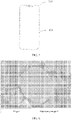
- the terminal 200 includes a housing 201 assembled on an outer side of the terminal, and a circuit board and a battery (not shown in the figure) that are located inside the housing 201.
- the battery and the circuit board are electrically connected to supply power to the circuit board.
- the battery is the battery provided in the foregoing embodiments of the present invention.
- the housing 201 may include a front housing assembled on a front side of the terminal and a rear cover assembled on a rear side. The battery may be fastened to an inner side of the rear cover.
- Embodiments of the present invention are further described below by using a plurality of embodiments.
- a production method of a negative electrode material includes the following steps: Graphite AG powder whose median particle diameter D50 is 5 ⁇ m, hydrogen peroxide, phosphoric acid, and ammonium persulfate are mixed and dispersed in water based on a mass ratio of 10:1:2:1, to produce slurry whose solid content is 45%, and a dehydration reaction is performed on the slurry at 150°C for 8 hours. Then, a temperature of the slurry rises to 550°C at a speed of 3 °C/min under protection of nitrogen, and low-temperature pre-carbonization processing is performed on the slurry for 2 hours.
- the slurry After being cooled to a room temperature, the slurry is transferred to a vacuum furnace, and a vacuum degree is adjusted to be within 10 Pa. Next, the temperature of the slurry rises to 1050°C at a speed of 2°C/min, and high-temperature carbonization processing is performed on the slurry for 4 hours. After being cooled to the room temperature, the slurry passes through a standard mesh net that has 300 meshes, to obtain a graphite negative electrode material doped with both P and O. In the negative electrode material, the P and O elements form C-P-O chemical bonds with a graphite matrix.
- FIG. 6 is a cross-sectional SEM view of a graphite negative electrode material that is doped with both P and O and that is produced in Embodiment 1 of the present invention. As shown in the figure, a cross-sectional structure of the material is flat, and there is no hole inside the material.
- FIG. 7 is a diagram of distribution of P elements of a graphite negative electrode material that is doped with both P and O and that is produced in Embodiment 1 of the present invention. It may be learned from the figure that the P elements are evenly doped in the graphite negative electrode material.
- a production method of a negative electrode material includes the following steps: Petroleum asphalt whose softening point is 280 °C is produced, by using an airflow pulverization classifier, into asphalt powder whose median particle diameter D50 is 5 ⁇ m.
- the obtained asphalt powder, ammonium persulfate, phosphoric acid, and phosphazene are mixed and dispersed in water based on a mass ratio of 10:1:2:1, to produce slurry whose solid content is 50%, and a dehydration reaction is performed on the slurry at 180°C for 4 hours.
- a temperature of the slurry rises to 600°C at a speed of 3°C/min under protection of nitrogen, and low-temperature pre-carbonization processing is performed on the slurry for 1 hour.
- the slurry is transferred to a vacuum furnace, and a vacuum degree is adjusted to be within 10 Pa.
- the temperature of the slurry rises to 1000°C at a speed of 2°C/min, and high-temperature carbonization processing is performed on the slurry for 6 hours.
- the slurry passes through a standard mesh net that has 300 meshes, to obtain a hard-carbon negative electrode material doped with P, O, and N.
- the P, O, and N elements form C-P-O and C-P-N chemical bonds with a hard-carbon matrix.
- a production method of a negative electrode material includes the following steps:
- a production method of a negative electrode material includes the following steps:
- a production method of a negative electrode material includes the following steps:
- Graphite AG powder is dispersed in water to produce slurry whose solid content is 45%, and a graphite negative electrode material in Comparative example 1 is produced based on a method the same as the method in Embodiment 1.
- Petroleum asphalt whose softening point is 280 °C is produced, by using an airflow pulverization classifier, into powder whose median particle diameter D50 is 5 ⁇ m.
- the obtained powder is dispersed in water to produce slurry whose solid content is 50%, and a hard-carbon negative electrode material in Comparative example 2 is produced based on a method the same as the method in Embodiment 2.
- Coal tar pitch whose softening point is 250°C is produced, by using an airflow pulverization classifier, into powder whose median particle diameter D50 is 5 ⁇ m.
- the obtained powder is dispersed in water to produce slurry whose solid content is 45%, and a silicon carbon/graphite negative electrode material having a coating layer in Comparative example 3 is produced based on a method the same as the method in Embodiment 3.
- Coal tar pitch whose softening point is 280°C is produced, by using an airflow pulverization classifier, into powder whose median particle diameter D50 is 5 ⁇ m.
- the obtained powder is dispersed in water to produce slurry whose solid content is 55%, and a silicon oxide/graphite negative electrode material having a coating layer in Comparative example 4 is produced based on a method the same as the method in Embodiment 4.
- Graphite AG powder whose median particle diameter D50 is 8 ⁇ m is dispersed in water to produce slurry whose solid content is 55%, and a nano-silicon/graphite composite negative electrode material in Comparative example 5 is produced based on a method the same as the method in Embodiment 5.
- a half-cell test method is used to respectively perform a first charging and discharging performance test and a rate test on a lithium-ion battery and a sodium-ion battery in which the negative electrode materials in Embodiments 1 to 5 of the present invention and Comparative examples 1 to 5 of the present invention are used. Results are listed in Table 1 and Table 2.
- the half-cell test method is as follows: A polyvinylidene fluoride solution whose mass fraction is 6% to 7% is produced by using N-methylpyrrolidone as a solvent.
- the negative electrode material, polyvinylidene fluoride, and conductive carbon black are evenly mixed based on a mass ratio of 80:10:10, and are coated on copper foil.
- a coated electrode plate is placed into a vacuum drying oven with a temperature of 90 °C for vacuum drying for 4 hours, and then rolled to a plate with a surface density of 4 mg/cm 2 for later use.
- a 2032-type button cell is assembled in a glove box filled with argon.
- a charging and discharging voltage ranges from 5 mV to 3.0 V
- a lithium-extraction capacity at 0.1C and corresponding initial coulombic efficiency are tested, and fast charging performance at 1C, 2C, and 3C is tested.
- a battery in which a negative electrode material including a doped carbon material is used has high initial coulombic efficiency and good fast charging performance.
- the negative electrode material in embodiments of the present invention includes the doped carbon material, and the doped carbon material includes at least two types of doping elements.
- the at least two types of doping elements form C-Ma-Mb chemical bonds with a carbon-based matrix, and formation of the C-Ma-Mb chemical bonds has the following beneficial effects: (1) In C-Ma-Mb, because Ma and C atoms form bonds, a quantity of vacancy defects on a carbon lattice is reduced, and a graphitization-like degree of the material is improved, so that conducting performance and initial coulombic efficiency of the material are improved.
- C-Ma-Mb exists in the carbon lattice or an edge, and due to a large radius of a doping atom, a distance between carbon layers is increased, a transport path of active ions is broadened, resistance of diffusion and transport of the ions between the layers is reduced, and fast charging performance of the material is improved.
- the doping elements whose electronegativity is greater than 2.55 exist in C-Ma-Mb, surface wettability of the material is greatly improved, so that the ions are transported more smoothly, interface impedance and diffusion impedance are greatly reduced, and fast charging performance of the material is improved.
- Ma and Mb in C-Ma-Mb are introduced, a quantity of binding and storage sites of the active ions is increased, and a specific capacity of the material is improved.
- the negative electrode material in Comparative examples 1 to 5 is an undoped carbon material.
- a large quantity of active ions are consumed in the first charging process, and low coulombic efficiency and poor rate performance are exhibited. This is not conducive to fast charging.
Landscapes
- Chemical & Material Sciences (AREA)
- Chemical Kinetics & Catalysis (AREA)
- Electrochemistry (AREA)
- General Chemical & Material Sciences (AREA)
- Engineering & Computer Science (AREA)
- Manufacturing & Machinery (AREA)
- Inorganic Chemistry (AREA)
- Composite Materials (AREA)
- Materials Engineering (AREA)
- Organic Chemistry (AREA)
- Life Sciences & Earth Sciences (AREA)
- General Life Sciences & Earth Sciences (AREA)
- Geology (AREA)
- Crystallography & Structural Chemistry (AREA)
- Battery Electrode And Active Subsutance (AREA)
Abstract
Description
- This application claims priority to
Chinese Patent Application No. 201911171298.1, filed with China National Intellectual Property Administration on November 25, 2019 - Embodiments of the present invention relate to the field of lithium-ion battery technologies, and in particular, to a negative electrode material, a production method thereof, a battery, and a terminal.
- With development of the Internet and popularity of portable electronic devices, people increasingly depend on smart mobile electronic devices, and a life problem of a battery becomes increasingly prominent. A most common idea is to lengthen a life of the battery by increasing a capacity of the battery, and a fast charging technology is a more proper solution to the life problem. For fast charging, currently, a main solution in the industry is to improve a fast charging capability of the battery by using a circuit design. With the circuit design, the fast charging capability is improved to some extent. For example, fast charging in which the battery is charged to 80% of capacity in 30 minutes is implemented. However, to implement faster charging, or even fast charging at a minute level, a charging current is larger. In this case, a higher requirement is imposed on fast charging performance of a negative electrode material of the battery. However, currently, for either a conventional graphite negative electrode material or a novel high-capacity silicon-based negative electrode material, due to a limitation caused by an intrinsic structure of the material, when the charging current is excessively large, active ions (such as lithium ions) diffuse slowly, and dendrites are very easily formed. Consequently, cell swelling and cycle attenuation are caused, and even fire and explosion are caused in a serious case. Therefore, to implement faster charging, a novel fast charging negative electrode material needs to be developed when an energy density is not lost.
- In view of this, embodiments of the present invention provide a negative electrode material, where the negative electrode material includes a doped carbon material, and a part of doping elements in the doped carbon material form C-Ma-Mb chemical bonds with a carbon-based matrix, so that fast charging performance of the negative electrode material is effectively improved, and a problem of poor fast charging performance of an existing negative electrode material is resolved to some extent.
- Specifically, a first aspect of embodiments of the present invention provides a negative electrode material, including a doped carbon material, where the doped carbon material includes a carbon-based matrix and doping elements doped in the carbon-based matrix, the doping elements include at least two of B, N, O, P, S, and F, at least a part of the doping elements form C-Ma-Mb chemical bonds with the carbon-based matrix, and Ma and Mb represent two different types of doping elements.
- In an implementation of the present invention, the carbon-based matrix includes one or more of artificial graphite, natural graphite, hard carbon, soft carbon, mesocarbon microbeads, carbon nanotubes, graphene, carbon fibers, active carbon, porous carbon, acetylene black, and Ketjen black.
- In an implementation of the present invention, a mass content of the doping elements in the doped carbon material is less than or equal to 5%. Specifically, the mass content of the doping elements ranges from 0.1% to 5%.
- In an implementation of the present invention, a median particle diameter of the doped carbon material ranges from 1 nm to 30 µm.
- In an implementation of the present invention, the negative electrode material includes primary particles or secondary particles of the doped carbon material. A median particle diameter of the primary particle of the doped carbon material may range from 1 µm to 10 µm, and a median particle diameter of the secondary particle of the doped carbon material may range from 3 µm to 30 µm.
- In an implementation of the present invention, the negative electrode material further includes a protective layer disposed on a surface of the primary particle or the secondary particle of the doped carbon material, and the protective layer includes a carbon layer and/or a conductive polymer layer.
- In another implementation of the present invention, the negative electrode material further includes other negative electrode active components, and the doped carbon material is composited with the other negative electrode active components to form composite particles.
- In an implementation of the present invention, the other negative electrode active components include one or more of a carbon-based material, a silicon-based material, a tin-based material, a germanium-based material, a metal compound, and a metal alloy.
- In a specific implementation of the present invention, the doped carbon material and the other negative electrode active components are evenly distributed in the composite particles.
- In an implementation of the present invention, the negative electrode material further includes a protective layer disposed on a surface of the composite particle, and the protective layer includes a carbon layer and/or a conductive polymer layer.
- In another specific implementation of the present invention, the composite particle includes a core that includes the other negative electrode active components, and a coating layer disposed on a surface of the core, and the coating layer includes the doped carbon material.
- In an implementation of the present invention, a thickness of the coating layer ranges from 1 nm to 100 nm.
- In an implementation of the present invention, a mass ratio of the coating layer to the core ranges from 0.1:100 to 5:100.
- The negative electrode material provided in the first aspect of embodiments of the present invention includes the doped carbon material, and at least a part of the doping elements in the doped carbon material form the C-Ma-Mb chemical bonds with the carbon-based matrix. Because the C-Ma-Mb chemical bonds are formed, a distance between carbon layers is increased, so that a transport path of active ions is broadened, resistance of diffusion and transport of the ions between the layers is reduced, and fast charging performance of the material is improved. In addition, because Ma-Mb and C atoms form bonds, a quantity of vacancy defects on a carbon lattice is reduced, and a graphitization-like degree of the material is improved, so that conducting performance and initial coulombic efficiency of the material are improved. Furthermore, because the doping elements Ma and Mb are introduced, a quantity of binding and storage sites of the active ions is increased, and a specific capacity of the negative electrode material is improved.
- According to a second aspect, an embodiment of the present invention further provides a production method of a negative electrode material, including:
- mixing a carbon source precursor and a doping element source, and enabling the carbon source precursor and the doping element source to react at 100°C to 180°C, to obtain a modified carbon source precursor; and
- performing low-temperature pre-carbonization processing on the obtained modified carbon source precursor in a protective atmosphere at 500 °C to 800 °C, and then performing high-temperature carbonization processing on the obtained modified carbon source precursor at 900 °C to 1150°C, to obtain a doped carbon material after cooling, where the doped carbon material includes a carbon-based matrix and doping elements doped in the carbon-based matrix, the doping elements include at least two of B, N, O, P, S, and F, at least a part of the doping elements form C-Ma-Mb chemical bonds with the carbon-based matrix, and Ma and Mb represent two different types of doping elements.
- In an implementation of the present invention, the foregoing production method further includes: mixing, granulating, sintering, and crushing the doped carbon material and other negative electrode active components, to obtain composite particles formed after the doped carbon material is composited with the other negative electrode active components, where the doped carbon material and the other negative electrode active components are evenly distributed in the composite particles.
- In an implementation of the present invention, the foregoing production method further includes: mixing, sintering in an inert atmosphere, and crushing the doped carbon material and the other negative electrode active components, to obtain composite particles formed after the doped carbon material is composited with the other negative electrode active components, where the composite particle includes a core that includes the other negative electrode active components, and a coating layer coating a surface of the core, and the coating layer includes the doped carbon material.
- In an implementation of the present invention, the doping element source includes at least two types of elements of B, N, O, P, S, and F.
- In this implementation of the present invention, the doping element source is selected from one or more of phosphoric acid, lithium phosphate, nitric acid, citric acid, performic acid, phosphorus pentoxide, ethylenediamine, ammonium dihydrogen phosphate, diammonium phosphate, urea, ammonia water, hydrogen peroxide, melamine, boric acid, boron trioxide, boron nitride, sulfonated polystyrene, thioacetamide, ammonium persulfate, thiourea, sodium sulfate, lithium fluoride, pyrrole, pyridine, thiophene, imidazole, silicon tetrafluoride, aluminum fluoride, calcium fluoride, phosphazene, pentafluorocyclotriphosphazene, ethoxy (pentafluoro) cyclotriphosphazene, hexachlorocyclotriphosphazene, hexadecyl trimethyl ammonium bromide, dimethyl sulfone, L-cysteine, and ammonia hydrogen fluoride.
- In an implementation of the present invention, the method for mixing a carbon source precursor and a doping element source includes one or more of a physical ball milling method, a low-temperature melting method, a mechanical fusion method, a high-temperature sintering method, an epitaxial growth method, a vapor deposition method, a magnetron sputtering method, a sol-gel method, a microwave reaction method, a hydrothermal method, and a solvothermal method.
- In an implementation of the present invention, the specific operation of mixing a carbon source precursor and a doping element source, and enabling the carbon source precursor and the doping element source to react at 100 °C to 180°C is as follows:
dispersing the carbon source precursor and the doping element source in water, and enabling the carbon source precursor and the doping element source to react at 100 °C to 180°C for 4 to 18 hours. - The production method provided in the second aspect of embodiments of the present invention has a simple process, is easy to control, and is suitable for industrial production.
- A third aspect of embodiments of the present invention provides a battery, including a positive electrode plate, a negative electrode plate, a separator, and an electrolyte. The negative electrode plate includes a negative electrode active material, and the negative electrode active material includes the negative electrode material according to the first aspect of the present invention.
- In an implementation of the present invention, the battery includes a lithium-ion battery, a sodium-ion battery, a potassium-ion battery, a magnesium-ion battery, a zinc-ion battery, a lithium-sulfur battery, an aluminum-ion battery, or a lithium-air battery.
- The battery provided in this embodiment of the present invention has good fast charging performance, so that a life problem of an existing battery is resolved to some extent.
- An embodiment of the present invention further provides a terminal, including a terminal housing, and a circuit board and a battery that are located inside the terminal housing, where the battery is electrically connected to the circuit board to supply power to the circuit board, and the battery includes the battery according to the third aspect of embodiments of the present invention.
-
-
FIG. 1 is a schematic diagram of a structure of a lithium-ion battery according to an embodiment of the present invention; -
FIG. 2 is a schematic diagram of a structure of a dopedcarbon material 10 according to an embodiment of the present invention; -
FIG. 3 is a schematic diagram of forming C-Ma-Mb chemical bonds by doping elements and a carbon-based matrix according to an embodiment of the present invention; -
FIG. 4A and FIG. 4B are respectively schematic working diagrams of an existing undoped carbon material and a doped carbon material according to an embodiment of the present invention during charging; -
FIG. 5 is a schematic diagram of a structure of a terminal according to an embodiment of the present invention; -
FIG. 6 is a cross-sectional SEM (Scanning Electron Microscope, scanning electron microscope) view of a graphite negative electrode material doped with both P and O according toEmbodiment 1 of the present invention; -
FIG. 7 is a diagram of distribution of P elements of a graphite negative electrode material doped with both P and O in EDS (Energy Dispersive X-Ray Spectroscopy, energy dispersive X-ray spectroscopy) according toEmbodiment 1 of the present invention; and -
FIG. 8 is an XPS (X-ray Photoelectron Spectroscopy, X-ray photoelectron spectroscopy) view of a graphite negative electrode material doped with both P and O according toEmbodiment 1 of the present invention. - The following describes embodiments of the present invention with reference to the accompanying drawings in embodiments of the present invention.
- Embodiments of the present invention provide a negative electrode material, and the negative electrode material may be used to manufacture a negative electrode of a rechargeable battery. The rechargeable battery may be a lithium-ion battery, a sodium-ion battery, a potassium-ion battery, a magnesium-ion battery, a zinc-ion battery, a lithium-sulfur battery, an aluminum-ion battery, a lithium-air battery, or the like.
- As shown in
FIG. 1 , core components of a lithium-ion battery include apositive electrode material 101, anegative electrode material 102, anelectrolyte 103, aseparator 104, and a corresponding connection accessory and loop. Thepositive electrode material 101 and thenegative electrode material 102 may be used to extract/insert lithium ions to store and release energy. The electrolyte acts as a carrier for transporting the lithium ions between a positive electrode and a negative electrode. Theseparator 104 may allow the lithium ions to pass through, but is not conductive, so that the positive electrode and the negative electrode are separated to avoid a short circuit. A charging and discharging mechanism of a rechargeable battery is as follows: During charging, active ions (Li+, Na+, K+, Mg2+, Zn2+, Al3+, and the like) are extracted from a lattice of the positive electrode material, and enter a lattice of the negative electrode material after passing through the electrolyte. During discharging, the active ions are extracted from the negative electrode material, and enter the lattice of the positive electrode material after passing through the electrolyte. When a charging current is excessively large, due to a small distance between layers, a graphite-based electrode material or a silicon-carbon electrode material has a limited capability to receive the active ions, and the active ions may finally form dendrites. Consequently, a battery capacity and cycle performance are attenuated, and a safety risk may be caused in a serious case. Especially, when the active ions are lithium ions or sodium ions, a current electrode material is far from meeting an application scenario in which charging is performed by using a large current. Therefore, an electrode material that has super-fast charging capability needs to be developed. - As shown in
FIG. 2 , a negative electrode material provided in an embodiment of the present invention includes a dopedcarbon material 10. The dopedcarbon material 10 includes a carbon-basedmatrix 1 anddoping elements 2 doped in the carbon-basedmatrix 1. Thedoping elements 2 include at least two of B, N, O, P, S, and F. At least a part of thedoping elements 2 form C-Ma-Mb chemical bonds with the carbon-basedmatrix 1. Ma and Mb represent two different types ofdoping elements 2. - In an implementation of the present invention, the C-Ma-Mb chemical bond indicates that Ma forms a chemical bond with C, and Ma forms a chemical bond with Mb. A specific bonding manner and a specific configuration are not limited. Single-bond bonding, double-bond bonding, or three-bond bonding may exist. In other words, C-Ma-Mb only indicates that C, Ma, and Mb have a bonding relationship.
FIG. 3 is a schematic diagram of forming C-Ma-Mb chemical bonds by doping elements and a carbon-based matrix. In C-Ma-Mb, Ma and Mb may be any two different elements that are of B, N, O, P, S, and F, and that may form a chemical bond. For example, C-Ma-Mb may be specifically C-P-O, C-O-P, C-N-F, C-P-N, C-S-O, C-S-P, C-N-O, C-N-B, C-N-P, C-N-S, C-B-O, C-N-O, and the like. The dopedcarbon material 10 in this embodiment of the present invention may include one or more types of C-Ma-Mb chemical bonds. For example, in an implementation of the present invention, two types of chemical bonds C-P-O and C-P-N may be included. In another implementation of the present invention, two types of chemical bonds C-P-O and C-N-B may be included. In another implementation of the present invention, two types of chemical bonds C-P-O and C-P-S may be included, or two types of chemical bonds C-P-O and C-S-O may be included. Certainly, in another implementation of the present invention, other two types of C-Ma-Mb chemical bonds may be included, or three, four, or more types of C-Ma-Mb chemical bonds may be included. - It should be noted that, in an implementation of the present invention, the
doping elements 2 doped in the carbon-basedmatrix 1 do not necessarily all form the C-Ma-Mb chemical bonds, and some doping elements may form C-Ma or C-Mb chemical bonds with the carbon-based matrix. In an implementation of the present invention, optionally, a proportion of a mass of doping elements, forming the C-Ma-Mb chemical bonds, to a total mass of the doping elements is greater than 50%. Specifically, the proportion of the mass of the doping elements, forming the C-Ma-Mb chemical bonds, to the total mass of the doping elements may be 60%, 70%, 80%, 90%, or greater than 90%. - In an implementation of the present invention, the carbon-based
matrix 1 may be one or more of artificial graphite, natural graphite, hard carbon, soft carbon, mesocarbon microbeads, carbon nanotubes, graphene, carbon fibers, active carbon, porous carbon, acetylene black, and Ketjen black. - In an implementation of the present invention, based on different electronegativity of the doping elements (boron B 2.04, phosphorus P 2.19, carbon C 2.55, sulfur S 2.58, nitrogen N 3.04, oxygen O 3.44, and fluorine F 3.98), the doping elements have different capabilities to attract electrons in a compound. When a difference between electronegativity of different doping elements is less than 2.0, covalent bonds are formed between atoms in corresponding doping elements, to obtain stable bonds of C-Ma-Mb (for example, C-P-O, C-O-P, C-N-F, C-P-N, C-S-O, C-S-P, C-N-O, C-N-B, C-N-P, C-N-S, C-B-O, or C-N-O). Bonding between Ma and carbon atoms protects unstable active oxidation sites on a surface of a carbon lattice, so that integrity of the carbon lattice and chemical stability of the surface of the carbon lattice are improved. In addition, doping atoms that have a large radius in the carbon lattice and C-Ma-Mb jointly broaden a distance between carbon layers, and C-Ma-Mb repairs defects on the carbon lattice, so that a graphitization-like degree is improved, and a microcrystalline structure of the carbon material is optimized. In addition, because doping elements whose electronegativity is greater than 2.55 exist in C-Ma-Mb, wettability of solvated active ions to the carbon lattice may be improved, to facilitate fast transport of the ions in an interface. Therefore, existence of C-Ma-Mb optimizes a chemical property of the surface of the carbon lattice and the microcrystalline structure of carbon, so that electrochemical performance is significantly improved.
- It should be noted that, in this embodiment of the present invention, the C-Ma-Mb chemical bond only indicates that Ma forms a chemical bond with C, and Ma forms a chemical bond with Mb, but a specific configuration is not limited. A C-P-O chemical bond is used as an example, and the C-P-O chemical bond may specifically include three types of configurations: C3-P=O, C2-P=O(-O), and C-P-O. The C3-P=O configuration has highest stability, and is a main configuration existing in the carbon lattice. The C-P-O configuration is a metastable configuration, and has a second-highest content. A trigonal pyramidal configuration such as the C3-P=O configuration is conducive to broadening the distance between the layers, and may repair vacancy defects to improve the graphitization-like degree, so as to optimize a carbon-based microcrystalline structure, facilitate fast transport of the ions in the interface, and finally significantly improve electrochemical performance.
FIG. 4A and FIG. 4B are respectively schematic working diagrams of an existing undoped carbon material and a doped carbon material according to an embodiment of the present invention during. As shown in the figures, in the doped carbon material provided in this embodiment of the present invention, existence of C3-P=O broadens the distance between the carbon layers, and facilitates transport of the ions. The C3-P=O configuration may play a positive role in improving surface wettability, rate performance, a reversible fast charging/discharging capability, a specific capacitance, and the like of the material. Certainly, when phosphorus and oxygen are doped in the carbon-based matrix, unstable configurations C3-P and C-O-P may further exist in the carbon lattice, but have a small content. - In an implementation of the present invention, a mass content of the doping elements in the doped
carbon material 10 is less than or equal to 5%. In an implementation of the present invention, the mass content of the doping elements ranges from 0.1% to 5%. In another implementation of the present invention, the mass content of the doping elements ranges from 2% to 4%. When a doping amount is greater than 5%, initial coulombic efficiency of the negative electrode material is greatly affected. When elements with a proper amount are doped, fast charging performance of the carbon-based matrix can be improved without greatly affecting initial coulombic efficiency. - In an implementation of the present invention, a median particle diameter of the doped carbon material ranges from 1 nm to 30 µm. Specifically, a doped carbon material that has a suitable particle diameter size may be selected based on a specific application manner. The doped carbon material may be primary particles or secondary particles. A median particle diameter of the primary particle of the doped carbon material may range from 1 µm to 10 µm, and a median particle diameter of the secondary particle of the doped carbon material may range from 3 µm to 30 µm.
- An existence form of the doped carbon material included in the negative electrode material provided in this embodiment of the present invention is not limited. In some embodiments of the present invention, the doped carbon material may be directly used as the negative electrode material to produce a negative electrode. In some other embodiments of the present invention, the doped carbon material may be composited with other negative electrode active components to form composite particles, and then a negative electrode is produced. A specific manner in which the doped carbon material is composited with the other negative electrode active components to form the composite particles may be as follows: The doped carbon material and the other negative electrode active components are evenly mixed and then granulated to obtain the composite particles; or the other negative electrode active components may be used as a core, and the doped carbon material may be used as a housing to coat a surface of the core. Certainly, simple physical mixing may be performed on the doped carbon material in this embodiment of the present invention and the other negative electrode active materials to produce a negative electrode.
- In an implementation of the present invention, the negative electrode material includes the primary particles or the secondary particles of the doped carbon material. In other words, the doped carbon material is directly used as the negative electrode material to produce a negative electrode. In this implementation, to improve performance of the negative electrode material, the negative electrode material may further include a protective layer disposed on a surface of the primary particle or the secondary particle of the doped carbon material, and the protective layer may be a carbon layer and/or a conductive polymer layer. In some embodiments, a material of the carbon layer may be specifically soft carbon, hard carbon, amorphous carbon, carbon nanotubes, and graphene that are obtained by decomposing a carbon source, and a compound including one or more thereof. A conductive polymer of the conductive polymer layer may be but not limited to one or more of polyacetylene, polypyrrole, polythiophene, poly (3,4-ethylenedioxythiophene)/poly(styrenesulfonate), polyaniline, polyphenylene, and poly(phenylenevinylene). A thickness of the protective layer may range from 5 nm to 50 nm, and further, may range from 10 nm to 20 nm. The protective layer can avoid excessive surface side effects caused because an electrolyte is in direct contact with the doped carbon material, to reduce an irreversible capacity and a loss of active ions in a battery, and may further increase an electronic conducting capability of the material, and improve fast charging performance of the material.
- In another implementation of the present invention, the negative electrode material further includes other negative electrode active components, and the doped carbon material is composited with the other negative electrode active components to form composite particles. The doped carbon material and the other negative electrode active components are evenly distributed in the composite particles. A mass ratio of the other negative electrode active materials to the doped carbon material may be selected based on an actual case.
- In an implementation of the present invention, in the composite particles formed by the doped carbon material and the other negative electrode active components, a median particle diameter of the doped carbon material ranges from 1 nm to 30 µm. In a specific implementation, the median particle diameter of the doped carbon material in the composite particles ranges from 50 nm to 10 µm. Further, the median particle diameter of the doped carbon material may range from 100 nm to 8 µm.
- In a specific implementation of the present invention, in the composite particles, the doped carbon material may be composited with the other negative electrode active components by using asphalt as a connection medium, and the asphalt is sintered to form carbon. In other words, the composite particles further include a carbon material that connects the doped carbon material and the other negative electrode active components.
- In some implementations of the present invention, the negative electrode material may further include a protective layer disposed on a surface of the composite particle, and the protective layer may be a carbon layer and/or a conductive polymer layer. The protective layer is as previously described, and details are not described herein again.
- In another implementation of the present invention, the negative electrode material further includes other negative electrode active components, and the doped carbon material is composited with the other negative electrode active components to form composite particles. The composite particle includes a core that includes the other negative electrode active components, and a coating layer disposed on a surface of the core. The coating layer includes the doped carbon material. A thickness of the coating layer may range from 1 nm to 100 nm. Further, the thickness of the coating layer may range from 10 nm to 100 nm, 20 nm to 80 nm, or 50 nm to 70 nm. A mass ratio of the coating layer to the core may range from 0.1:100 to 5:100. In some embodiments of the present invention, the mass ratio of the coating layer to the core may range from 1:100 to 4:100. In some other embodiments, the mass ratio of the cladding layer to the core may range from 2:100 to 3:100. A suitable amount of coating may improve fast charging performance of the material and alleviate a side reaction between the material and the electrolyte without affecting a capacity and initial coulombic efficiency of the material. In an implementation of the present invention, the coating layer may include only the doped carbon material, or may include both the doped carbon material and a conductive polymer. The conductive polymer may be but not limited to one or more of polyacetylene, polypyrrole, polythiophene, poly (3,4-ethylenedioxythiophene)/poly(styrenesulfonate), polyaniline, polyphenylene, and poly(phenylenevinylene). In some implementations of the present invention, the doped carbon material as a material of the coating layer may have a median particle diameter ranging from 1 nm to 50 nm. A doped carbon material that has a small particle diameter is selected to produce the coating layer, so that the thickness and surface morphology of the coating layer can be better controlled, and a specific surface area of the material can be reduced.
- The other negative electrode active components mentioned in this embodiment of the present invention may be one or more of a carbon-based material, a silicon-based material, a tin-based material, a germanium-based material, a metal compound, and a metal alloy. Specifically, the carbon-based material may be one or more of artificial graphite (AG), natural graphite (NG), hard carbon (HC), soft carbon, mesocarbon microbeads (CMCB), carbon nanotubes (CNT), graphene, carbon fibers, active carbon, porous carbon, acetylene black (AB), and Ketjen black. The silicon-based material may be one or more of silicon (including nano-silicon, micron-silicon, and the like), silicon oxide, silicon monoxide (SiOx, where 0.3<x<1.7), a silicon-carbon composite (Si/C), porous silicon, and thin-film silicon. The tin-based material may be one or more of metallic tin (Sn), tin carbon (Sn/C), porous tin, and thin-film tin. The germanium-based material may be one or more of metallic germanium (Ge), germanium carbon (Ge/C), porous germanium, and thin-film germanium. The metal compound may be one or more of nickel oxide, iron oxide, cobalt oxide, manganese oxide, zinc oxide, copper oxide, tin oxide, germanium oxide, molybdenum oxide, molybdenum sulfide, iron sulfide, and lithium titanate. The metal alloy may be one or more of lithium metal, lithiumaluminum alloy, lithium-tin alloy, lithium-silicon alloy, lithium-germanium alloy, and lithium-carbon alloy.
- The negative electrode material in this embodiment of the present invention includes the doped carbon material, and the doping elements in the doped carbon material form the C-Ma-Mb chemical bonds with the carbon-based matrix. Therefore, the negative electrode material has the following beneficial effects: (1) In C-Ma-Mb, because Ma and C atoms form bonds, a quantity of vacancy defects on the carbon lattice is reduced, and the graphitization-like degree of the material is improved, so that conducting performance and initial coulombic efficiency of the material are improved. (2) C-Ma-Mb exists in the carbon lattice or an edge, so that the distance between the carbon layers is increased, a transport path of active ions is broadened, resistance of diffusion and transport of the ions between the layers is reduced, and fast charging performance of the material is improved. (3) Because the doping elements whose electronegativity is greater than 2.55 exist in C-Ma-Mb, surface wettability of the material may be improved, so that the ions are transported more smoothly, interface impedance and diffusion impedance are greatly reduced, a stable working voltage window of an electrode is improved, and fast charging performance of the material is improved. (4) Because Ma and Mb in C-Ma-Mb are introduced, a quantity of binding and storage sites of the active ions is increased, and a specific capacity of the negative electrode material is improved.
- Correspondingly, an embodiment of the present invention further provides a production method of a negative electrode material, including:
- Step (1): Mix a carbon source precursor and a doping element source, and enable the carbon source precursor and the doping element source to react at 100°C to 180°C, to obtain a modified carbon source precursor.
- Step (2): Perform low-temperature pre-carbonization processing on the obtained modified carbon source precursor in a protective atmosphere at 500 °C to 800 °C, and then perform high-temperature carbonization processing on the obtained modified carbon source precursor at 900 °C to 1150°C, to obtain a doped carbon material after cooling, where the doped carbon material includes a carbon-based matrix and doping elements doped in the carbon-based matrix, the doping elements include at least two of B, N, O, P, S, and F, at least a part of the doping elements form C-Ma-Mb chemical bonds with the carbon-based matrix, and Ma and Mb represent two different types of doping elements.
- In an implementation of the present invention, in step (1), the carbon source precursor may be a material in which a mass content of carbon elements ranges from 80% to 99%, a mass content of hydrogen elements ranges from 1% to 15%, and a mass content of oxygen elements ranges from 0% to 5%. A softening point of the carbon source precursor is less than 200°C. A median particle diameter D50 of the carbon source precursor may range from 2 µm to 15 µm, and a maximum particle diameter Dmax thereof is less than 70 µm. Specifically, the carbon source precursor may be selected from at least one of graphite and coal tar pitch, petroleum asphalt, or modified Courmarone resin whose softening point is greater than 200°C.
- In step (1), the doping element source includes at least two types of elements of B, N, O, P, S, and F. The doping element source may be a substance, and the substance includes at least two types of elements of B, N, O, P, S, and F. Alternatively, two or more substances may be combined to include at least two types of elements of B, N, O, P, S, and F. Specifically, the doping element source may be selected from one or more of phosphoric acid, lithium phosphate, nitric acid, citric acid, performic acid, phosphorus pentoxide, ethylenediamine, ammonium dihydrogen phosphate, diammonium phosphate, urea, ammonia water, hydrogen peroxide, melamine, boric acid, boron trioxide, boron nitride, sulfonated polystyrene, thioacetamide, ammonium persulfate, thiourea, sodium sulfate, lithium fluoride, pyrrole, pyridine, thiophene, imidazole, silicon tetrafluoride, aluminum fluoride, calcium fluoride, phosphazene, pentafluorocyclotriphosphazene, ethoxy (pentafluoro) cyclotriphosphazene, hexachlorocyclotriphosphazene, hexadecyl trimethyl ammonium bromide, dimethyl sulfone, L-cysteine, and ammonia hydrogen fluoride. Amass ratio of the doping element source to the carbon source precursor may range from 5:100 to 30:100.
- In step (1), the method for mixing a carbon source precursor and a doping element source includes one or more of a physical ball milling method, a low-temperature melting method, a mechanical fusion method, a high-temperature sintering method, an epitaxial growth method, a vapor deposition method, a magnetron sputtering method, a sol-gel method, a microwave reaction method, a hydrothermal method, and a solvothermal method. In a specific embodiment of the present invention, deionized water may be used as a solvent to stir and mix the carbon source precursor and the doping element source at a high speed, and a mass ratio of the carbon source precursor to the deionized water ranges from 30:100 to 60:100.
- In step (1), the specific operation of mixing a carbon source precursor and a doping element source, and enabling the carbon source precursor and the doping element source to react at 100°C to 180°C is as follows:
dispersing the carbon source precursor and the doping element source in water, and performing a dehydration reaction on the carbon source precursor and the doping element source at 100°C to 180°C for 4 to 18 hours. In this step, doping elements are deposited on a surface of the carbon source precursor, and are diffused into the carbon source as the reaction proceeds, to form bonds with carbon atoms. - In an implementation of the present invention, in step (2), a temperature for low-temperature pre-carbonization may be specifically 500°C, 600°C, 700°C, or 800°C, time for low-temperature pre-carbonization may range from 1 hour to 3 hours, and a content of volatile components of a product obtained after low-temperature pre-carbonization may be controlled between 3% and 8%. A temperature for high-temperature carbonization may range from 900 °C to 1150°C. Specifically, the temperature for high-temperature carbonization may be 900 °C, 950 °C, 1000°C, 1100°C, or 1150°C. Time for high-temperature carbonization may range from 2 hours to 10 hours. High-temperature carbonization processing is performed under a vacuum of 1 Pa to 1000 Pa. Specifically, a vacuum carbonization furnace may be used. Low-temperature pre-carbonization may remove most volatile components. Performing high-temperature carbonization processing under the vacuum helps an unstable configuration that is in a carbon lattice and that includes doping elements evolve into a stable configuration. A configuration that includes phosphorus is used as an example. In a process of high-temperature carbonization processing, unstable C3-P and CO-P configurations are transformed into more stable C3-P=O configurations and a small portion of metastable C-P-O configurations. The C3-P=O configurations enable the carbon lattice to become more ordered and complete, and increase a distance between layers. Optimization of the phosphorus configuration enables a chemical property of a surface of the carbon-based matrix to be more stable, and also effectively improves electrochemical performance of the material.
- In step (2), after high-temperature carbonization processing and cooling, a mesh net may be used based on an actual case. For example, a standard mesh net that has more than 80 meshes may be used. The modified carbon source precursor may be cooled to 0°C to 80°C.
- In step (2), a median particle diameter D50 of the doped carbon material ranges from 1 nm to 30 µm, a maximum particle diameter Dmax thereof is less than 90 µm, and a content of the doping elements is below 5%. The doped carbon material that is produced in step (2) and that has a large particle diameter may be pulverized to a material that has a target particle diameter. A specific pulverization method may be but not limited to airflow pulverization classification and mechanical pulverization classification.
- In some embodiments of the present invention, the foregoing production method may further include: mixing, sintering in an inert atmosphere, and crushing the doped carbon material and other negative electrode active components, to obtain composite particles formed after the doped carbon material is composited with the other negative electrode active components. The composite particle includes a core that includes the other negative electrode active components, and a coating layer coating a surface of the core. The coating layer includes the doped carbon material. A doped carbon material whose median particle diameter ranges from 1 nm to 50 nm may be selected to be mixed with the other negative electrode active components.
- In an implementation of the present invention, the method for mixing the doped carbon material and other negative electrode active components may be a physical ball milling method, a low-temperature melting method, a mechanical fusion method, a high-temperature sintering method, an epitaxial growth method, a vapor deposition method, a magnetron sputtering method, a sol-gel method, a microwave reaction method, a hydrothermal method, and a solvothermal method. In a specific embodiment of the present invention, a step of using the mechanical fusion method is as follows: The doped carbon material and the other negative electrode active components that serve as the core are placed into a fusion machine to be stirred and mixed at a high speed. A stirring speed is 10 revolutions per minute to 2000 revolutions per minute, and stirring time is 0.1 hour to 12 hours.
- In some other embodiments of the present invention, the foregoing production method may further include: mixing, granulating, sintering, and crushing the doped carbon material and other negative electrode active components, to obtain composite particles formed after the doped carbon material is composited with the other negative electrode active components. The doped carbon material and the other negative electrode active components are evenly distributed in the composite particles. In some implementations of the present invention, a doped carbon material whose median particle diameter ranges from 50 nm to 10 µm may be selected to be mixed with the other negative electrode active components. In an implementation of the present invention, in a granulating process, a small amount of asphalt may be added as a connection medium. In a sintering process, the asphalt is carbonized into carbon, and the asphalt plays a role of bonding and granulation.
- In an implementation of the present invention, the method for mixing the doped carbon material and other negative electrode active components may be a physical ball milling method, a low-temperature melting method, a mechanical fusion method, a high-temperature sintering method, an epitaxial growth method, a vapor deposition method, a magnetron sputtering method, a sol-gel method, a microwave reaction method, a hydrothermal method, and a solvothermal method. In a specific embodiment of the present invention, a step of using the low-temperature melting method is as follows: The doped carbon material and the other negative electrode active component are placed into a high-speed mixer to be stirred and mixed. A stirring speed is 10 revolutions per minute to 1000 revolutions per minute, and stirring time is 0.1 hour to 12 hours.
- In an implementation of the present invention, for granulation processing, asphalt may be added into a high-speed mixer, and temperature programming is performed for granulation. A temperature rise speed may be 1°C per minute to 10°C per minute. A temperature may be 150°C to 500°C. A softening point of the asphalt is 50°C to 200°C. A median particle diameter D50 of the asphalt is 2 µm to 15 µm, and a maximum particle diameter Dmax thereof is less than 70 µm.
- In an implementation of the present invention, for sintering processing in the foregoing production method, a carbonization furnace may be used, a temperature may be 300°C to 800°C, and sintering time may be 2 hours to 10 hours.
- In an implementation of the present invention, airflow pulverization classification and/or mechanical pulverization classification may be used to perform crushing processing in the foregoing production method.
- In an implementation of the present invention, the protective atmosphere and the inert atmosphere in the foregoing production method may be specifically at least one of nitrogen, helium, and argon.
- An embodiment of the present invention further provides a battery, including a positive electrode plate, a negative electrode plate, a separator, and an electrolyte. The negative electrode plate includes a negative electrode active material, and the negative electrode active material includes the foregoing negative electrode material provided in embodiments of the present invention. The battery may be a lithium-ion battery, a sodium-ion battery, a potassium-ion battery, a magnesium-ion battery, a zinc-ion battery, a lithium-sulfur battery, an aluminum-ion battery, or a lithium-air battery. The foregoing battery may be used in a terminal consumer product, such as a mobile phone, a tablet computer, a portable computer, a notebook computer, and another wearable or movable electronic device.
- As shown in
FIG. 5 , an embodiment of the present invention further provides a terminal 200. The terminal 200 may be a mobile phone, or may be an electronic product such as a tablet computer, a notebook computer, a portable computer, and a smart wearable product. The terminal 200 includes ahousing 201 assembled on an outer side of the terminal, and a circuit board and a battery (not shown in the figure) that are located inside thehousing 201. The battery and the circuit board are electrically connected to supply power to the circuit board. The battery is the battery provided in the foregoing embodiments of the present invention. Thehousing 201 may include a front housing assembled on a front side of the terminal and a rear cover assembled on a rear side. The battery may be fastened to an inner side of the rear cover. - Embodiments of the present invention are further described below by using a plurality of embodiments.
- A production method of a negative electrode material includes the following steps:
Graphite AG powder whose median particle diameter D50 is 5 µm, hydrogen peroxide, phosphoric acid, and ammonium persulfate are mixed and dispersed in water based on a mass ratio of 10:1:2:1, to produce slurry whose solid content is 45%, and a dehydration reaction is performed on the slurry at 150°C for 8 hours. Then, a temperature of the slurry rises to 550°C at a speed of 3 °C/min under protection of nitrogen, and low-temperature pre-carbonization processing is performed on the slurry for 2 hours. After being cooled to a room temperature, the slurry is transferred to a vacuum furnace, and a vacuum degree is adjusted to be within 10 Pa. Next, the temperature of the slurry rises to 1050°C at a speed of 2°C/min, and high-temperature carbonization processing is performed on the slurry for 4 hours. After being cooled to the room temperature, the slurry passes through a standard mesh net that has 300 meshes, to obtain a graphite negative electrode material doped with both P and O. In the negative electrode material, the P and O elements form C-P-O chemical bonds with a graphite matrix. -
FIG. 6 is a cross-sectional SEM view of a graphite negative electrode material that is doped with both P and O and that is produced inEmbodiment 1 of the present invention. As shown in the figure, a cross-sectional structure of the material is flat, and there is no hole inside the material.FIG. 7 is a diagram of distribution of P elements of a graphite negative electrode material that is doped with both P and O and that is produced inEmbodiment 1 of the present invention. It may be learned from the figure that the P elements are evenly doped in the graphite negative electrode material.FIG. 8 is a diagram of distribution of phosphorus configurations of a graphite negative electrode material that is doped with both P and O and that is produced inEmbodiment 1 of the present invention. As shown inFIG. 8 , in the negative electrode material, C3-P=O configurations are most widely distributed, C-P-O configurations are second widely distributed, and C-O-P configurations and C3-P configurations are few. - A production method of a negative electrode material includes the following steps:
Petroleum asphalt whose softening point is 280 °C is produced, by using an airflow pulverization classifier, into asphalt powder whose median particle diameter D50 is 5 µm.The obtained asphalt powder, ammonium persulfate, phosphoric acid, and phosphazene are mixed and dispersed in water based on a mass ratio of 10:1:2:1, to produce slurry whose solid content is 50%, and a dehydration reaction is performed on the slurry at 180°C for 4 hours. Then, a temperature of the slurry rises to 600°C at a speed of 3°C/min under protection of nitrogen, and low-temperature pre-carbonization processing is performed on the slurry for 1 hour. After being cooled to a room temperature, the slurry is transferred to a vacuum furnace, and a vacuum degree is adjusted to be within 10 Pa. Next, the temperature of the slurry rises to 1000°C at a speed of 2°C/min, and high-temperature carbonization processing is performed on the slurry for 6 hours. After being cooled to the room temperature, the slurry passes through a standard mesh net that has 300 meshes, to obtain a hard-carbon negative electrode material doped with P, O, and N. In the negative electrode material, the P, O, and N elements form C-P-O and C-P-N chemical bonds with a hard-carbon matrix. - A production method of a negative electrode material includes the following steps:
- (1) Coal tar pitch whose softening point is 250 °C is produced, by using an airflow pulverization classifier, into powder whose median particle diameter D50 is 5 µ m. The obtained pitch powder, hydrogen peroxide, performic acid, and phosphoric acid are mixed and dispersed in water based on a mass ratio of 10:1:1:2, to produce slurry whose solid content is 45%, and a dehydration reaction is performed on the slurry at 180°C for 4 hours. Then, a temperature of the slurry rises to 600°C at a speed of 3°C/min under protection of nitrogen, and low-temperature pre-carbonization processing is performed on the slurry for 1 hour. After being cooled to a room temperature, the slurry is transferred to a vacuum furnace, and a vacuum degree is adjusted to be within 10 Pa. Next, the temperature of the slurry rises to 1000°C at a speed of 2°C/min, and high-temperature carbonization processing is performed on the slurry for 6 hours. After being cooled to the room temperature, the slurry passes through a standard mesh net that has 300 meshes, to obtain a hard-carbon material doped with both P and O. The P and O elements form C-P-O chemical bonds with a carbon matrix.
- (2) The hard-carbon material that is doped with both P and O and that is obtained in step (1) is pulverized by using an airflow pulverization method, so that D50 is 1 µm. Then, the hard-carbon material and a silicon carbon/graphite composite material SiC/AG (a capacity per gram is 500 mAh/g) are placed into a fusion machine to be stirred and mixed at a high speed. A stirring speed is 1000 revolutions per minute, and stirring time is 1 hour.
- (3) A product obtained in step (2) is placed into a carbonization furnace for sintering processing. A sintering temperature is 800°C, sintering time is 3 hours, and a sintering atmosphere is nitrogen.
- (4) A sintering product in step (3) is pulverized by using a mechanical pulverization method, so that D50 is 12 µm, to obtain a silicon carbon/graphite negative electrode material that has a doped carbon material coating layer. The negative electrode material includes a silicon carbon/graphite core, and a hard-carbon material that is doped with both P and O and that coats a surface of the core.
- A production method of a negative electrode material includes the following steps:
- (1) Coal tar pitch whose softening point is 280 °C is produced, by using an airflow pulverization classifier, into powder whose median particle diameter D50 is 5 µm. The obtained pitch powder, ammonium persulfate, ethoxy (pentafluoro) cyclotriphosphazene, and hexadecyl trimethyl ammonium bromide are mixed and dispersed in water based on a mass ratio of 10:1:2:1, to produce slurry whose solid content is 55%, and a dehydration reaction is performed on the slurry at 150°C for 8 hours. Then, a temperature of the slurry rises to 550°C at speed of 3°C/min under protection of nitrogen, and low-temperature pre-carbonization processing is performed on the slurry for 2 hours. After being cooled to a room temperature, the slurry is transferred to a vacuum furnace, and a vacuum degree is adjusted to be within 10 Pa. Next, the temperature of the slurry rises to 1050°C at speed of 2°C/min, and high-temperature carbonization processing is performed on the slurry for 4 hours. After being cooled to the room temperature, the slurry passes through a standard mesh net that has 300 meshes, to obtain a hard-carbon material doped with both P and O. The P and O elements form C-P-O chemical bonds with a carbon matrix;
- (2) The hard-carbon material that is doped with both P and O and that is obtained in step (1) is pulverized by using an airflow pulverization method, so that D50 is 0.5 µm. Then the hard-carbon material and a silicon oxide/graphite composite material SiO/AG (a capacity per gram is 500 mAh/g) are placed into a fusion machine to be stirred and mixed at a high speed. A stirring speed is 2000 revolutions per minute, and stirring time is 0.5 hour.
- (3) A product obtained in step (2) is placed into a carbonization furnace for sintering processing. A sintering temperature is 600°C, sintering time is 3 hours, and a sintering atmosphere is nitrogen.
- (4) A sintering product obtained in step (3) is pulverized by using a mechanical pulverization method, so that D50 is 15 µm, to obtain a silicon oxide/graphite negative electrode material that has a doped carbon material coating layer. The negative electrode material includes a silicon oxide/graphite core, and a hard-carbon material that is doped with both P and O and that coats a surface of the core.
- A production method of a negative electrode material includes the following steps:
- (1) Graphite AG powder whose median particle diameter D50 is 8 µm, ammonium persulfate, phosphoric acid, and melamine are mixed and dispersed in water based on a mass ratio of 10:1:2:1, to produce slurry whose solid content is 55%, and a dehydration reaction is performed on the slurry at 180°C for 4 hours. Then, a temperature of the slurry rises to 650 °C at a speed of 3 °C/min under protection of nitrogen, and low-temperature pre-carbonization processing is performed on the slurry for 1 hour. After being cooled to a room temperature, the slurry is transferred to a vacuum furnace, and a vacuum degree is adjusted to be within 10 Pa. Next, the temperature of the slurry rises to 1050°C at a speed of 2°C/min, and high-temperature carbonization processing is performed on the slurry for 4 hours. After being cooled to the room temperature, the slurry passes through a standard mesh net that has 300 meshes, to obtain a graphite material doped with both P and O. The P and O elements form C-P-O chemical bonds with a graphite matrix.
- (2) The graphite material obtained in step (1) and nano-silicon (a particle diameter is 100 nm) are placed into a high-speed mixer for mixing. A stirring speed is 1000 revolutions per minute, and stirring time is 1 hour.
- (3) Asphalt whose softening point is 200°C and median particle diameter D50 is 3 µm is added into the mixture obtained in step (2), and temperature programming is performed for granulation. A temperature rise speed is 3°C per minute, and a temperature rises to 500°C.
- (4) A product obtained in step (3) is placed into a carbonization furnace for sintering processing. A sintering temperature is 800°C, sintering time is 3 hours, and a sintering atmosphere is nitrogen.
- (5) A sintering product in step (4) is pulverized by using a mechanical pulverization method, so that D50 is 12 µm, to obtain a graphite composite negative electrode material doped with nano-silicon/both P and O.
- Graphite AG powder is dispersed in water to produce slurry whose solid content is 45%, and a graphite negative electrode material in Comparative example 1 is produced based on a method the same as the method in
Embodiment 1. - Petroleum asphalt whose softening point is 280 °C is produced, by using an airflow pulverization classifier, into powder whose median particle diameter D50 is 5 µm. The obtained powder is dispersed in water to produce slurry whose solid content is 50%, and a hard-carbon negative electrode material in Comparative example 2 is produced based on a method the same as the method in
Embodiment 2. - Coal tar pitch whose softening point is 250°C is produced, by using an airflow pulverization classifier, into powder whose median particle diameter D50 is 5 µm. The obtained powder is dispersed in water to produce slurry whose solid content is 45%, and a silicon carbon/graphite negative electrode material having a coating layer in Comparative example 3 is produced based on a method the same as the method in Embodiment 3.
- Coal tar pitch whose softening point is 280°C is produced, by using an airflow pulverization classifier, into powder whose median particle diameter D50 is 5 µm. The obtained powder is dispersed in water to produce slurry whose solid content is 55%, and a silicon oxide/graphite negative electrode material having a coating layer in Comparative example 4 is produced based on a method the same as the method in Embodiment 4.
- Graphite AG powder whose median particle diameter D50 is 8 µm is dispersed in water to produce slurry whose solid content is 55%, and a nano-silicon/graphite composite negative electrode material in Comparative example 5 is produced based on a method the same as the method in Embodiment 5.
- To strongly support beneficial effects brought by technical solutions of embodiments of the present invention, a half-cell test method is used to respectively perform a first charging and discharging performance test and a rate test on a lithium-ion battery and a sodium-ion battery in which the negative electrode materials in
Embodiments 1 to 5 of the present invention and Comparative examples 1 to 5 of the present invention are used. Results are listed in Table 1 and Table 2. The half-cell test method is as follows: A polyvinylidene fluoride solution whose mass fraction is 6% to 7% is produced by using N-methylpyrrolidone as a solvent. The negative electrode material, polyvinylidene fluoride, and conductive carbon black are evenly mixed based on a mass ratio of 80:10:10, and are coated on copper foil. A coated electrode plate is placed into a vacuum drying oven with a temperature of 90 °C for vacuum drying for 4 hours, and then rolled to a plate with a surface density of 4 mg/cm2 for later use. Next, a 2032-type button cell is assembled in a glove box filled with argon. An electrochemical performance test is performed on the assembled half-cell in an electrochemical detection system by using a three-component mixed solvent of 1 mol/L LiPF6 (a lithium-ion battery) or 1 mol/L NaPF6 (a sodium-ion battery) as an electrolyte based on EC:DMC:EMC=1:1:1 (a volume ratio), and by using a lithium metal plate (the lithium-ion battery) or a sodium metal plate (the sodium-ion battery) as a counter electrode. A charging and discharging voltage ranges from 5 mV to 3.0 V A lithium-extraction capacity at 0.1C and corresponding initial coulombic efficiency are tested, and fast charging performance at 1C, 2C, and 3C is tested.Table 1 Performance test results of lithium-ion batteries in which different negative electrode materials are used No. 0.1C lithium-extraction specific capacity mAh/g Initial coulombic efficiency (%) 1C/0.1C capacity retention rate % 2C/0.1C capacity retention rate % 3C/0.1C capacity retention rate % Embodiment 1 352 92 90 85 75 Embodiment 2555 84 95 92 85 Embodiment 3 510 91 92 88 80 Embodiment 4 505 90 88 82 70 Embodiment 5 1200 86 86 80 65 Comparative example 1 350 90 50 15 8 Comparative example 2 450 72 70 50 20 Comparative example 3 499 90 45 12 5 Comparative example 4 495 89 43 12 6 Comparative example 5 1100 82 40 8 5 Table 2 Performance test results of sodium-ion batteries in which different negative electrode materials are used No. 0.1C sodiumextraction specific capacity mAh/g Initial coulombic efficiency (%) 1C/0.1C capacity retention rate % 2C/0.1C capacity retention rate % 3C/0.1C capacity retention rate % Embodiment 2 350 85 95 90 80 Comparative example 2 250 70 85 80 70 - The above test results indicate that, compared with Comparative examples 1 to 5, in embodiments of the present invention, a battery in which a negative electrode material including a doped carbon material is used has high initial coulombic efficiency and good fast charging performance. A reason is that the negative electrode material in embodiments of the present invention includes the doped carbon material, and the doped carbon material includes at least two types of doping elements. The at least two types of doping elements form C-Ma-Mb chemical bonds with a carbon-based matrix, and formation of the C-Ma-Mb chemical bonds has the following beneficial effects: (1) In C-Ma-Mb, because Ma and C atoms form bonds, a quantity of vacancy defects on a carbon lattice is reduced, and a graphitization-like degree of the material is improved, so that conducting performance and initial coulombic efficiency of the material are improved. (2) C-Ma-Mb exists in the carbon lattice or an edge, and due to a large radius of a doping atom, a distance between carbon layers is increased, a transport path of active ions is broadened, resistance of diffusion and transport of the ions between the layers is reduced, and fast charging performance of the material is improved. (3) Because the doping elements whose electronegativity is greater than 2.55 exist in C-Ma-Mb, surface wettability of the material is greatly improved, so that the ions are transported more smoothly, interface impedance and diffusion impedance are greatly reduced, and fast charging performance of the material is improved. (4) Because Ma and Mb in C-Ma-Mb are introduced, a quantity of binding and storage sites of the active ions is increased, and a specific capacity of the material is improved.
- However, the negative electrode material in Comparative examples 1 to 5 is an undoped carbon material. A specified quantity of defect sites exist on a carbon lattice, a distance between carbon microcrystalline layers is small, and an electrolyte has poor wettability. As a result, a large quantity of active ions are consumed in the first charging process, and low coulombic efficiency and poor rate performance are exhibited. This is not conducive to fast charging.
Claims (24)
- A negative electrode material, comprising a doped carbon material, wherein the doped carbon material comprises a carbon-based matrix and doping elements doped in the carbon-based matrix, the doping elements comprise at least two of B, N, O, P, S, and F, at least a part of the doping elements form C-Ma-Mb chemical bonds with the carbon-based matrix, and Ma and Mb represent two different types of doping elements.
- The negative electrode material according to claim 1, wherein the carbon-based matrix comprises one or more of artificial graphite, natural graphite, hard carbon, soft carbon, mesocarbon microbeads, carbon nanotubes, graphene, carbon fibers, active carbon, porous carbon, acetylene black, and Ketjen black.
- The negative electrode material according to claim 1, wherein a mass content of the doping elements in the doped carbon material is less than or equal to 5%.
- The negative electrode material according to claim 1, wherein a median particle diameter of the doped carbon material ranges from 1 nm to 30 µm.
- The negative electrode material according to claim 1, wherein the negative electrode material is composed of primary particles or secondary particles of the doped carbon material.
- The negative electrode material according to claim 5, wherein a median particle diameter of the primary particle of the doped carbon material ranges from 1 µm to 10 µm, and a median particle diameter of the secondary particle of the doped carbon material ranges from 3 µm to 30 µm.
- The negative electrode material according to claim 5, wherein the negative electrode material further comprises a protective layer disposed on a surface of the primary particle or the secondary particle of the doped carbon material, and the protective layer comprises a carbon layer and/or a conductive polymer layer.
- The negative electrode material according to claim 1, wherein the negative electrode material further comprisesw, and the doped carbon material is composited with the other negative electrode active components to form composite particles.
- The negative electrode material according to claim 8, wherein the other negative electrode active components comprise one or more of a carbon-based material, a silicon-based material, a tin-based material, a germanium-based material, a metal compound, and a metal alloy.
- The negative electrode material according to claim 8, wherein the doped carbon material and the other negative electrode active components are evenly distributed in the composite particles.
- The negative electrode material according to claim 10, wherein the negative electrode material further comprises a protective layer disposed on a surface of the composite particle, and the protective layer comprises a carbon layer and/or a conductive polymer layer.
- The negative electrode material according to claim 8, wherein the composite particle comprises a core that is composed of the other negative electrode active components, and a coating layer disposed on a surface of the core, and the coating layer comprises the doped carbon material.
- The negative electrode material according to claim 12, wherein a thickness of the coating layer ranges from 1 nm to 100 nm.
- The negative electrode material according to claim 12, wherein a mass ratio of the coating layer to the core ranges from 0.1:100 to 5:100.
- A production method of a negative electrode material, comprising:mixing a carbon source precursor and a doping element source, and enabling the carbon source precursor and the doping element source to react at 100°C to 180°C, to obtain a modified carbon source precursor; andperforming low-temperature pre-carbonization processing on the obtained modified carbon source precursor in a protective atmosphere at 500 °C to 800 °C, and then performing high-temperature carbonization processing on the obtained modified carbon source precursor at 900°C to 1150°C, to obtain a doped carbon material after cooling, wherein the doped carbon material comprises a carbon-based matrix and doping elements doped in the carbon-based matrix, the doping elements comprise at least two of B, N, O, P, S, and F, at least a part of the doping elements form C-Ma-Mb chemical bonds with the carbon-based matrix, and Ma and Mb represent two different types of doping elements.
- The production method according to claim 15, further comprising: mixing, granulating, sintering, and crushing the doped carbon material and other negative electrode active components, to obtain composite particles formed after the doped carbon material is composited with the other negative electrode active components, wherein the doped carbon material and the other negative electrode active components are evenly distributed in the composite particles.
- The production method according to claim 15, further comprising: mixing, sintering in an inert atmosphere, and crushing the doped carbon material and other negative electrode active components, to obtain composite particles formed after the doped carbon material is composited with the other negative electrode active components, wherein the composite particle comprises a core that is composed of the other negative electrode active components, and a coating layer coating a surface of the core, and the coating layer comprises the doped carbon material.
- The production method according to claim 15, wherein the doping element source comprises at least two types of elements of B, N, O, P, S, and F.
- The production method according to claim 18, wherein the doping element source is selected from one or more of phosphoric acid, lithium phosphate, nitric acid, citric acid, performic acid, phosphorus pentoxide, ethylenediamine, ammonium dihydrogen phosphate, diammonium phosphate, urea, ammonia water, hydrogen peroxide, melamine, boric acid, boron trioxide, boron nitride, sulfonated polystyrene, thioacetamide, ammonium persulfate, thiourea, sodium sulfate, lithium fluoride, pyrrole, pyridine, thiophene, imidazole, silicon tetrafluoride, aluminum fluoride, calcium fluoride, phosphazene, pentafluorocyclotriphosphazene, ethoxy (pentafluoro) cyclotriphosphazene, hexachlorocyclotriphosphazene, hexadecyl trimethyl ammonium bromide, dimethyl sulfone, L-cysteine, and ammonia hydrogen fluoride.
- The production method according to claim 15, wherein the method for mixing a carbon source precursor and a doping element source comprises one or more of a physical ball milling method, a low-temperature melting method, a mechanical fusion method, a high-temperature sintering method, an epitaxial growth method, a vapor deposition method, a magnetron sputtering method, a sol-gel method, a microwave reaction method, a hydrothermal method, and a solvothermal method.
- The production method according to claim 15, wherein the specific operation of mixing a carbon source precursor and a doping element source, and enabling the carbon source precursor and the doping element source to react at 100°C to 180°C is as follows:
dispersing the carbon source precursor and the doping element source in water, and enabling the carbon source precursor and the doping element source to react at 100°C to 180°C for 4 to 18 hours. - A battery, comprising a positive electrode plate, a negative electrode plate, a separator, and an electrolyte, wherein the negative electrode plate comprises a negative electrode active material, and the negative electrode active material comprises the negative electrode material according to any one of claims 1 to 14.
- The battery according to claim 22, wherein the battery comprises a lithium-ion battery, a sodium-ion battery, a potassium-ion battery, a magnesium-ion battery, a zinc-ion battery, a lithium-sulfur battery, an aluminum-ion battery, or a lithium-air battery.
- A terminal, comprising a terminal housing, and a circuit board and a battery that are located inside the terminal housing, wherein the battery is electrically connected to the circuit board to supply power to the circuit board, and the battery comprises the battery according to either of claims 22 and 23.
Applications Claiming Priority (2)
| Application Number | Priority Date | Filing Date | Title |
|---|---|---|---|
| CN201911171298.1A CN112838197B (en) | 2019-11-25 | 2019-11-25 | Cathode material and preparation method thereof, battery and terminal |
| PCT/CN2020/130864 WO2021104201A1 (en) | 2019-11-25 | 2020-11-23 | Negative electrode material and preparation method therefor, battery, and terminal |
Publications (2)
| Publication Number | Publication Date |
|---|---|
| EP4057392A1 true EP4057392A1 (en) | 2022-09-14 |
| EP4057392A4 EP4057392A4 (en) | 2023-08-23 |
Family
ID=75922368
Family Applications (1)
| Application Number | Title | Priority Date | Filing Date |
|---|---|---|---|
| EP20892425.8A Pending EP4057392A4 (en) | 2019-11-25 | 2020-11-23 | Negative electrode material and preparation method therefor, battery, and terminal |
Country Status (4)
| Country | Link |
|---|---|
| US (1) | US20220285685A1 (en) |
| EP (1) | EP4057392A4 (en) |
| CN (2) | CN116190596A (en) |
| WO (1) | WO2021104201A1 (en) |
Families Citing this family (59)
| Publication number | Priority date | Publication date | Assignee | Title |
|---|---|---|---|---|
| CN113517442B (en) * | 2021-06-07 | 2023-03-24 | 宁德新能源科技有限公司 | Negative electrode material, electrochemical device, and electronic device |
| CN113506868B (en) * | 2021-06-28 | 2023-06-30 | 山东玉皇新能源科技有限公司 | Nonmetal-doped hard carbon negative electrode material and preparation method thereof |
| CN113540447B (en) * | 2021-06-29 | 2022-04-19 | 暨南大学 | Preparation and application of ultra-long cycle polyatomic doping hollow carbon electrode material |
| CN115566151B (en) * | 2021-07-02 | 2026-03-03 | 湖南中科星城石墨有限公司 | Graphite negative electrode material and preparation method and application thereof |
| CN113659143A (en) * | 2021-08-06 | 2021-11-16 | 东莞市创明电池技术有限公司 | Preparation method of negative electrode material of sodium ion battery, negative electrode material and sodium ion battery |
| CN115706211A (en) * | 2021-08-12 | 2023-02-17 | 贝特瑞新材料集团股份有限公司 | Negative electrode material, preparation method thereof and lithium ion battery |
| CN113809314B (en) * | 2021-08-16 | 2023-01-31 | 北京科技大学 | Preparation method and application of porous silicon carbon or germanium carbon material |
| CN113690420B (en) * | 2021-08-26 | 2023-03-03 | 厦门大学 | A nitrogen-sulfur-doped silicon-carbon composite material and its preparation method and application |
| CN113707863B (en) * | 2021-08-26 | 2023-04-14 | 蜂巢能源科技有限公司 | A kind of hard carbon composite material and its preparation method and application |
| US20230147558A1 (en) * | 2021-11-09 | 2023-05-11 | Microvast Power Systems Co., Ltd. | Negative electrode material and method of preparing the same |
| CN114094103B (en) * | 2021-11-16 | 2024-05-03 | 江苏超电新能源科技发展有限公司 | Preparation method and application of fluorine and sulfur doped lithium battery electrode conductive agent material |
| CN116177519B (en) * | 2021-11-29 | 2025-10-17 | 深圳市贝特瑞新能源技术研究院有限公司 | Carbon negative electrode material, preparation method and application thereof |
| CN116178442A (en) * | 2021-11-29 | 2023-05-30 | 宁德国泰华荣新材料有限公司 | A kind of preparation method of (2,2,2-trifluoroethoxy) pentafluorocyclotriphosphazene |
| CN114497546A (en) * | 2021-12-28 | 2022-05-13 | 贝特瑞新材料集团股份有限公司 | Graphite negative electrode material, preparation method thereof and lithium ion battery |
| CN114388805B (en) * | 2021-12-30 | 2024-04-30 | 华南师范大学 | Manganous fluoride-carbon composite material and preparation method and application thereof |
| CN114497451B (en) * | 2022-01-28 | 2024-03-19 | 上海兰钧新能源科技有限公司 | Negative electrode sheet and preparation method and application thereof |
| CN114583137B (en) * | 2022-03-17 | 2023-10-24 | 华中科技大学 | A method for sulfur-doped phosphorus modification on carbon surface and its application |
| CN114678512B (en) * | 2022-03-22 | 2023-10-13 | 惠州亿纬锂能股份有限公司 | Negative electrode material, preparation method thereof and battery |
| CN114914420B (en) * | 2022-05-17 | 2023-12-05 | 长沙理工大学 | Double-modified lithium ion battery anode material and preparation method thereof |
| CN114975890A (en) * | 2022-06-22 | 2022-08-30 | 湖北亿纬动力有限公司 | A kind of graphite material for negative pole piece, preparation method thereof, and lithium ion battery containing the same |
| CN115172701B (en) * | 2022-07-12 | 2024-11-26 | 西北大学 | Anion-regulated silicon-based microaggregate negative electrode material and preparation method and use thereof |
| CN115101814B (en) * | 2022-08-24 | 2022-12-09 | 宁德新能源科技有限公司 | Electrochemical device and electronic device |
| CN115414874B (en) * | 2022-08-31 | 2023-07-14 | 安普瑞斯(无锡)有限公司 | Multiple polyatomic co-doped carbon aerogel and preparation method and application thereof |
| CN115566145A (en) * | 2022-09-30 | 2023-01-03 | 江苏传艺钠离子电池研究院有限公司 | Preparation method of sodium ion battery cathode material and sodium ion battery |
| CN115332538B (en) * | 2022-10-12 | 2023-04-07 | 宁德新能源科技有限公司 | Hard carbon material, preparation method thereof, electrochemical device and electronic device |
| CN115692692B (en) * | 2022-11-04 | 2025-11-07 | 惠州锂威新能源科技有限公司 | Negative electrode active material, preparation method thereof and lithium ion battery |
| CN115611264A (en) * | 2022-11-10 | 2023-01-17 | 泰安市法拉第能源科技有限公司 | Asphalt-based hard carbon negative electrode material, preparation method thereof and sodium ion battery |
| CN116177523B (en) * | 2022-12-13 | 2025-07-15 | 赣州立探新能源科技有限公司 | A modified non-graphite carbon material and its preparation method and application |
| CN116022802B (en) * | 2022-12-15 | 2024-06-18 | 广州大学 | A non-metallic high entropy compound and its preparation method and application |
| CN115966667A (en) * | 2022-12-15 | 2023-04-14 | 天津巴莫科技有限责任公司 | Lithium-rich manganese-based cathode material and its preparation method and application |
| CN116130600A (en) * | 2022-12-21 | 2023-05-16 | 广州市融成锂能锂电池有限公司 | Stirring electrode negative electrode slurry based on ice block solvent and preparation method thereof |
| CN116789099A (en) * | 2022-12-27 | 2023-09-22 | 昆明理工大学 | Method for preparing hard carbon material by using anthracite and application thereof |
| CN116014105B (en) * | 2023-01-10 | 2025-07-25 | 西安交通大学 | Sulfur host material of lithium-sulfur battery and preparation method and application thereof |
| CN116154129A (en) * | 2023-02-07 | 2023-05-23 | 深圳市德方创域新能源科技有限公司 | Negative electrode material and preparation method thereof, negative electrode sheet, secondary battery |
| CN116395697A (en) * | 2023-04-10 | 2023-07-07 | 陕西科技大学 | A kind of double metal doped silicon carbon material, preparation method and application |
| CN116979026A (en) * | 2023-05-06 | 2023-10-31 | 宁德时代新能源科技股份有限公司 | Negative electrode plate, preparation method thereof, battery cell, battery and power utilization device |
| CN116654895B (en) * | 2023-05-31 | 2024-01-23 | 青岛新泰和纳米科技有限公司 | Phosphorus-tin co-doped hard carbon negative electrode material and preparation method thereof |
| CN116613300B (en) * | 2023-07-18 | 2023-09-22 | 成都锂能科技有限公司 | A coal-based carbonized sodium battery negative electrode material, its preparation method, and a sodium-ion battery containing the same |
| CN116715327B (en) * | 2023-07-25 | 2025-07-04 | 东华理工大学 | Preparation method of sulfonic acid functionalized N, P and B co-doped carbon material uranium electric adsorbent |
| CN116885174B (en) * | 2023-09-08 | 2024-01-23 | 浙江华宇钠电新能源科技有限公司 | Mixed doped carbon material and use thereof in sodium ion battery material for vehicles |
| CN117361495A (en) * | 2023-10-23 | 2024-01-09 | 广东工业大学 | A kind of porous carbon composite material, flexible electrode and preparation method and application thereof |
| CN117352727B (en) * | 2023-10-31 | 2024-12-10 | 深圳贝特瑞钠电新材料科技有限公司 | Negative electrode material and preparation method thereof, sodium ion battery |
| CN119833581A (en) * | 2023-12-14 | 2025-04-15 | 宁德时代新能源科技股份有限公司 | Silicon-carbon composite material and preparation method thereof, negative electrode sheet, secondary battery and device |
| CN117878387A (en) * | 2023-12-18 | 2024-04-12 | 雄安稀土功能材料创新中心有限公司 | Solid electrolyte material, preparation method, electrolyte layer and lithium ion battery |
| CN117832431B (en) * | 2023-12-25 | 2024-12-24 | 宁波倍特瑞新能源科技有限公司 | A lithium battery negative electrode material and preparation method thereof |
| CN118248874B (en) * | 2024-01-17 | 2024-09-24 | 碳一(安徽)钠电材料有限公司 | A hard carbon composite material and its preparation method and application |
| CN118255344A (en) * | 2024-03-26 | 2024-06-28 | 四川杉杉新材料有限公司 | Heteroatom doped coal-based hard carbon negative electrode material and preparation method and application thereof, battery |
| CN118306988A (en) * | 2024-04-26 | 2024-07-09 | 深圳珈钠能源科技有限公司 | Sodium ion battery hard carbon negative electrode material rich in broad-layer graphite microcrystals and preparation method thereof |
| CN118108211B (en) * | 2024-04-29 | 2024-07-12 | 浙江华宇钠电新能源科技有限公司 | Phosphorus-doped hard carbon negative electrode material, preparation method thereof and vehicle |
| CN118218587B (en) * | 2024-05-23 | 2024-08-02 | 河北奥冠电源有限责任公司 | N, P co-doped carbon-based composite material, preparation method thereof and application thereof in lead-carbon battery |
| CN118448616B (en) * | 2024-05-23 | 2025-11-07 | 泰苓科技(湖州)有限公司 | Preparation method and application of high specific energy and long-life composite anode material |
| CN118630204B (en) * | 2024-06-12 | 2025-11-11 | 比亚迪股份有限公司 | Negative electrode active material, preparation method and application thereof |
| CN118851172B (en) * | 2024-07-12 | 2025-11-18 | 烟台先进材料与绿色制造山东省实验室 | Multi-element doped porous carbon and its preparation method, silicon-carbon anode material and its preparation method and application |
| KR102950469B1 (en) * | 2024-08-30 | 2026-04-08 | 경상국립대학교산학협력단 | Anode Material for Lithium-Ion Batteries Including Fluorine and Nitrogen Co-Doped Carbon Conductive Agent, Method for Manufacturing the Same, and Lithium-Ion Batteries |
| CN118851772B (en) * | 2024-09-25 | 2025-02-07 | 苏州元脑智能科技有限公司 | Calcium fluoride doped silicon carbide preparation method, calcium fluoride doped silicon carbide, heat dissipation component and electronic equipment |
| CN119324219B (en) * | 2024-12-18 | 2025-05-13 | 惠州市豪鹏科技有限公司 | Graphite anode material, preparation method thereof, anode sheet and electrochemical device |
| CN119706795A (en) * | 2024-12-23 | 2025-03-28 | 万华化学集团股份有限公司 | A carbon material and its preparation method and application |
| CN120033305A (en) * | 2025-01-17 | 2025-05-23 | 宁德时代新能源科技股份有限公司 | Lithium ion secondary battery and its preparation method, power device and application |
| CN119660715B (en) * | 2025-01-26 | 2026-03-27 | 孝感楚能新能源创新科技有限公司 | A hard carbon anode material, its preparation method and application |
Family Cites Families (15)
| Publication number | Priority date | Publication date | Assignee | Title |
|---|---|---|---|---|
| US5294498A (en) * | 1991-03-02 | 1994-03-15 | Sony Corporation | Anode material, method for producing it and non-aqueous electrolyte cell employing such anode materials |
| CN103618071A (en) * | 2013-11-14 | 2014-03-05 | 中国科学院广州能源研究所 | Carbon-silicon composite negative electrode material of lithium ion battery and preparation method thereof |
| CN103887505A (en) * | 2014-04-14 | 2014-06-25 | 中南大学 | Application of functional carbon material and high-hydrogen-evolution substance doped functional carbon material |
| CN109119603B (en) * | 2014-04-29 | 2022-08-09 | 华为技术有限公司 | Composite negative electrode material, preparation method thereof, lithium ion secondary battery negative electrode piece and lithium ion secondary battery |
| CN104003368B (en) * | 2014-05-06 | 2016-05-11 | 北京理工大学 | A kind of porous phosphorus-nitrogen co-doped material with carbon element and preparation method thereof |
| CN104528703B (en) * | 2014-12-29 | 2017-02-01 | 中国科学院宁波材料技术与工程研究所 | Preparation method of nitrogen/phosphorus-codoped graphene |
| CN105932234A (en) * | 2016-05-05 | 2016-09-07 | 华东师范大学 | Doped porous carbon spheres used for negative electrode material of sodium ion battery and preparation method for doped porous carbon spheres |
| CN106025195B (en) * | 2016-05-12 | 2018-06-26 | 陕西科技大学 | A kind of preparation method of the sodium-ion battery carbon material used as anode containing multistage pore-size distribution |
| CN105810914B (en) * | 2016-05-13 | 2018-02-27 | 中南大学 | A kind of sodium-ion battery sulfur doping porous carbon materials and preparation method thereof |
| CN107221459A (en) * | 2017-05-27 | 2017-09-29 | 中国石油大学(北京) | A kind of nitrogen-phosphor codoping graphene and preparation method and application |
| CN107706360A (en) * | 2017-07-25 | 2018-02-16 | 深圳市沃特玛电池有限公司 | A kind of preparation method of composite cathode material for lithium ion cell |
| KR102278996B1 (en) * | 2017-10-27 | 2021-07-20 | 주식회사 엘지에너지솔루션 | Silicon-carbon composite, and lithium secondary battery comprising the same |
| CN108493424B (en) * | 2018-04-11 | 2020-11-03 | 中科锂电新能源有限公司 | A kind of nitrogen, phosphorus, sulfur co-doped composite carbon material, its preparation method and lithium ion battery |
| CN109970043B (en) * | 2019-04-08 | 2020-11-27 | 中国石油大学(华东) | Nitrogen-phosphorus co-doped carbon nanosheet and preparation method thereof, electrode for alkali metal ion battery, alkali metal ion battery and electric device |
| CN110085822B (en) * | 2019-04-18 | 2020-12-08 | 江苏理工学院 | A kind of F-N-C composite material and its preparation method and application |
-
2019
- 2019-11-25 CN CN202211670974.1A patent/CN116190596A/en active Pending
- 2019-11-25 CN CN201911171298.1A patent/CN112838197B/en active Active
-
2020
- 2020-11-23 EP EP20892425.8A patent/EP4057392A4/en active Pending
- 2020-11-23 WO PCT/CN2020/130864 patent/WO2021104201A1/en not_active Ceased
-
2022
- 2022-05-24 US US17/752,005 patent/US20220285685A1/en active Pending
Also Published As
| Publication number | Publication date |
|---|---|
| CN112838197A (en) | 2021-05-25 |
| CN112838197B (en) | 2022-12-27 |
| EP4057392A4 (en) | 2023-08-23 |
| CN116190596A (en) | 2023-05-30 |
| US20220285685A1 (en) | 2022-09-08 |
| WO2021104201A1 (en) | 2021-06-03 |
Similar Documents
| Publication | Publication Date | Title |
|---|---|---|
| US20220285685A1 (en) | Negative electrode material, production method thereof, battery, and terminal | |
| KR102192087B1 (en) | Anode active material, lithium battery comprising the same, and preparation method thereof | |
| KR101749187B1 (en) | Negative active material and negative electrode and lithium battery containing the material, and method for manufacturing the material | |
| KR102285149B1 (en) | Negative active material and lithium battery containing the material | |
| CN107710463A (en) | Positive electrode for lithium-sulfur battery, manufacturing method thereof, and lithium-sulfur battery comprising same | |
| CN103999266B (en) | active material for battery pack | |
| KR20030081160A (en) | Battery | |
| US12531232B2 (en) | Three-dimensional composite metallic lithium negative electrode, metallic lithium battery and apparatus | |
| US20240379961A1 (en) | Core-shell cathode lithium-supplementing additive, preparation method therefor and application thereof | |
| EP4435898A1 (en) | Positive electrode lithium supplement additive and preparation method therefor, positive sheet, and secondary battery | |
| US20200227741A1 (en) | Cathode material and electrochemical device including cathode material | |
| US20260031350A1 (en) | Positive electrode active material and preparation method therefor, positive electrode plate, battery, and electrical apparatus | |
| KR20220075740A (en) | Metal-Carbon Composite Anode material for lithium secondary battery, method for manufacturing the same and lithium secondary battery comprising the same | |
| KR20220088221A (en) | Metal-Carbon Composite Anode material for lithium secondary battery, method for manufacturing the same and lithium secondary battery comprising the same | |
| KR102415162B1 (en) | A manufacturing method of sulfur-selenium-carbon complex, a cathode for lithium secondary battery comprising the sulfur-selenium-carbon complex manufactured by the same, and lithium sulfur-selenium battery comprising the same | |
| CN113921801A (en) | Lithium-supplementing material, positive electrode material, and lithium ion secondary battery | |
| WO2024244388A1 (en) | Phosphate composite positive electrode active material and preparation method therefor, positive electrode sheet, battery cell, battery and electric device | |
| CN114678512B (en) | Negative electrode material, preparation method thereof and battery | |
| CN115732675B (en) | Lithium ion battery positive electrode material, preparation method thereof, lithium ion battery and electronic equipment | |
| KR102483066B1 (en) | Composite material comprising selenium, method of fabricating of the same, lithium ion and lithium selenium secondary battery and lithium ion capacitor comprising the same | |
| WO2025185439A1 (en) | Negative electrode active particle, preparation method therefor, negative electrode sheet, battery, and electronic device | |
| KR101587882B1 (en) | Manufacturing method of carbon-coated NbO₂ as negative electrode active material for lithium ion secondary battery | |
| Wang et al. | Coassembly of Ultrathin Lithium with Dual Lithium-Free Electrodes for Long-Lasting Sulfurized Polyacrylonitrile Batteries | |
| KR101895902B1 (en) | Positive active material for rechargeable lithium battery, method of preparing the same, and rechargeable lithium battery including the same | |
| KR102480473B1 (en) | Lithium secondary battery and method of fabricating the same |
Legal Events
| Date | Code | Title | Description |
|---|---|---|---|
| STAA | Information on the status of an ep patent application or granted ep patent |
Free format text: STATUS: THE INTERNATIONAL PUBLICATION HAS BEEN MADE |
|
| PUAI | Public reference made under article 153(3) epc to a published international application that has entered the european phase |
Free format text: ORIGINAL CODE: 0009012 |
|
| STAA | Information on the status of an ep patent application or granted ep patent |
Free format text: STATUS: REQUEST FOR EXAMINATION WAS MADE |
|
| 17P | Request for examination filed |
Effective date: 20220607 |
|
| AK | Designated contracting states |
Kind code of ref document: A1 Designated state(s): AL AT BE BG CH CY CZ DE DK EE ES FI FR GB GR HR HU IE IS IT LI LT LU LV MC MK MT NL NO PL PT RO RS SE SI SK SM TR |
|
| DAV | Request for validation of the european patent (deleted) | ||
| DAX | Request for extension of the european patent (deleted) | ||
| RIC1 | Information provided on ipc code assigned before grant |
Ipc: H01M 12/08 20060101ALI20230404BHEP Ipc: H01M 10/054 20100101ALI20230404BHEP Ipc: H01M 10/0525 20100101ALI20230404BHEP Ipc: H01M 4/62 20060101ALI20230404BHEP Ipc: H01M 4/583 20100101ALI20230404BHEP Ipc: H01M 4/38 20060101ALI20230404BHEP Ipc: H01M 4/36 20060101ALI20230404BHEP Ipc: C01B 32/20 20170101ALI20230404BHEP Ipc: C01B 32/00 20170101ALI20230404BHEP Ipc: H01M 4/1393 20100101ALI20230404BHEP Ipc: H01M 4/133 20100101ALI20230404BHEP Ipc: H01M 4/587 20100101AFI20230404BHEP |
|
| A4 | Supplementary search report drawn up and despatched |
Effective date: 20230721 |
|
| RIC1 | Information provided on ipc code assigned before grant |
Ipc: H01M 12/08 20060101ALI20230717BHEP Ipc: H01M 10/054 20100101ALI20230717BHEP Ipc: H01M 10/0525 20100101ALI20230717BHEP Ipc: H01M 4/62 20060101ALI20230717BHEP Ipc: H01M 4/583 20100101ALI20230717BHEP Ipc: H01M 4/38 20060101ALI20230717BHEP Ipc: H01M 4/36 20060101ALI20230717BHEP Ipc: C01B 32/20 20170101ALI20230717BHEP Ipc: C01B 32/00 20170101ALI20230717BHEP Ipc: H01M 4/1393 20100101ALI20230717BHEP Ipc: H01M 4/133 20100101ALI20230717BHEP Ipc: H01M 4/587 20100101AFI20230717BHEP |