EP4057337B1 - Electronic device adopting heat dissipation structure - Google Patents
Electronic device adopting heat dissipation structure Download PDFInfo
- Publication number
- EP4057337B1 EP4057337B1 EP22152268.3A EP22152268A EP4057337B1 EP 4057337 B1 EP4057337 B1 EP 4057337B1 EP 22152268 A EP22152268 A EP 22152268A EP 4057337 B1 EP4057337 B1 EP 4057337B1
- Authority
- EP
- European Patent Office
- Prior art keywords
- substrate
- electronic device
- disposed
- heat dissipation
- layer
- Prior art date
- Legal status (The legal status is an assumption and is not a legal conclusion. Google has not performed a legal analysis and makes no representation as to the accuracy of the status listed.)
- Active
Links
Images



Classifications
-
- H—ELECTRICITY
- H10—SEMICONDUCTOR DEVICES; ELECTRIC SOLID-STATE DEVICES NOT OTHERWISE PROVIDED FOR
- H10W—GENERIC PACKAGES, INTERCONNECTIONS, CONNECTORS OR OTHER CONSTRUCTIONAL DETAILS OF DEVICES COVERED BY CLASS H10
- H10W40/00—Arrangements for thermal protection or thermal control
- H10W40/10—Arrangements for heating
-
- H—ELECTRICITY
- H10—SEMICONDUCTOR DEVICES; ELECTRIC SOLID-STATE DEVICES NOT OTHERWISE PROVIDED FOR
- H10W—GENERIC PACKAGES, INTERCONNECTIONS, CONNECTORS OR OTHER CONSTRUCTIONAL DETAILS OF DEVICES COVERED BY CLASS H10
- H10W40/00—Arrangements for thermal protection or thermal control
- H10W40/70—Fillings or auxiliary members in containers or in encapsulations for thermal protection or control
-
- H—ELECTRICITY
- H10—SEMICONDUCTOR DEVICES; ELECTRIC SOLID-STATE DEVICES NOT OTHERWISE PROVIDED FOR
- H10W—GENERIC PACKAGES, INTERCONNECTIONS, CONNECTORS OR OTHER CONSTRUCTIONAL DETAILS OF DEVICES COVERED BY CLASS H10
- H10W74/00—Encapsulations, e.g. protective coatings
- H10W74/10—Encapsulations, e.g. protective coatings characterised by their shape or disposition
- H10W74/111—Encapsulations, e.g. protective coatings characterised by their shape or disposition the semiconductor body being completely enclosed
- H10W74/121—Encapsulations, e.g. protective coatings characterised by their shape or disposition the semiconductor body being completely enclosed by multiple encapsulations, e.g. by a thin protective coating and a thick encapsulation
-
- H—ELECTRICITY
- H10—SEMICONDUCTOR DEVICES; ELECTRIC SOLID-STATE DEVICES NOT OTHERWISE PROVIDED FOR
- H10W—GENERIC PACKAGES, INTERCONNECTIONS, CONNECTORS OR OTHER CONSTRUCTIONAL DETAILS OF DEVICES COVERED BY CLASS H10
- H10W76/00—Containers; Fillings or auxiliary members therefor; Seals
- H10W76/40—Fillings or auxiliary members in containers, e.g. centering rings
- H10W76/42—Fillings
- H10W76/47—Solid or gel fillings
-
- H—ELECTRICITY
- H10—SEMICONDUCTOR DEVICES; ELECTRIC SOLID-STATE DEVICES NOT OTHERWISE PROVIDED FOR
- H10W—GENERIC PACKAGES, INTERCONNECTIONS, CONNECTORS OR OTHER CONSTRUCTIONAL DETAILS OF DEVICES COVERED BY CLASS H10
- H10W76/00—Containers; Fillings or auxiliary members therefor; Seals
- H10W76/10—Containers or parts thereof
- H10W76/12—Containers or parts thereof characterised by their shape
Definitions
- the disclosure relates to an electronic device, and more particularly to an electronic device that adopts a heat dissipation structure for dissipating heat from a heat-generating structure.
- a liquid metal is a metal or a metal alloy that is in a liquid state at room temperature due to its low melting point or that is in a liquid state when heated to its melting point.
- liquid metal include gallium indium tin alloy, indium bismuth tin alloy, and indium bismuth zinc alloy.
- Liquid metals have high stability and exceptional thermal and electrical conductivity. Moreover, the specific heat capacity and thermal conductivity of the liquid metals are much higher than those of the traditional silicone conductive pastes, so that they are now used as a thermal conductive agent between a heat source and heat-dissipating fins.
- Aluminum or copper is often used as the main material for heat-dissipating fins.
- aluminum is easily corroded by gallium in the liquid metal, resulting in the damage of the heat-dissipating fins and losing the thermal conductivity of the liquid metal.
- copper has a much stable electron configuration due to the 10 electrons in its 3d orbital, and thus, copper does not corrode as easily as aluminum when in contact with gallium. Referring to FIG. 1 , in actual practice, after a period of time and under high temperature, copper can still react with gallium to form a needle-like intermetallic compound CuGa, which is also known as liquid metal dry-out.
- CN211982421U discloses a heat dissipation device including a heat sink, and a liquid metal layer arranged between the heat source and the heat sink, and the heat sink includes a sheet body facing the heat source, and an anti-corrosion metal layer plated on the sheet body. The liquid metal layer is attached to the anti-corrosion metal layer of the heat sink.
- WO2020162417 discloses a structure in which a metal having fluidity is utilized as a heat conductive material. In this structure, a heat conductive material is prevented from invading an unintended region even when a positional change of a semiconductor device occurs or a vibration occurs.
- an object of the present disclosure is to provide an electronic device that adopts a heat dissipation structure and that can alleviate at least one of the drawbacks of the prior art.
- an electronic device that includes a heat-generating structure and a heat dissipation structure.
- the heat-generating structure includes a substrate, an electronic component disposed on the substrate, and at least one electronic element disposed on the substrate and spaced apart from the electronic component.
- the heat dissipation structure includes a heat dissipation unit, a liquid metal layer, a blocking member, a fixing adhesive, an insulation layer, and a cushioning adhesive.
- the heat dissipation unit includes a heat dissipation body and an anti-corrosion layer formed on the heat dissipation body.
- the liquid metal layer is disposed between the electronic component and the heat dissipation body, and abuts against the anti-corrosion layer.
- the blocking member is disposed between the substrate and the anti-corrosion layer, is connected to the substrate, and surrounds the liquid metal layer and the electronic component.
- the fixing adhesive is disposed on the substrate, and is located between the electronic component and the blocking member.
- the insulation layer is disposed between the substrate and the anti-corrosion layer.
- the cushioning adhesive is disposed between the blocking member and the anti-corrosion layer.
- An insulation glue is disposed between said insulation layer and said substrate and encapsulating said at least one electronic element, wherein said insulation layer extends from said blocking member to said fixing adhesive and covers said insulation glue, and said cushioning adhesive is clamped between said insulation layer and said anti-corrosion layer.
- a first embodiment of an electronic device 3 includes a heat-generating structure 2, and a heat dissipation structure 1 for dissipating heat from the heat-generating structure 2.
- the heat-generating structure 2 includes a substrate 21, an electronic component 22 disposed on the substrate 21, and a plurality of electronic elements 23 disposed on the substrate 1 and spaced apart from the electronic component 22.
- the heat-generating structure 2 may be, for example, but not limited to, a central processing unit (CPU) or a graphics processing unit (GPU).
- the substrate 21 includes a printed circuit layer 211 located on top thereof, but is not limited thereto.
- the electronic elements 23 may be capacitors or other components.
- the heat dissipation structure 1 includes a liquid metal layer 11, a heat dissipation unit 12, a blocking member 13, a fixing adhesive 15, an insulation layer 14, and a cushioning adhesive 16.
- the heat dissipation unit 12 includes a heat dissipation body 121 parallel to the substrate 21, and an anti-corrosion layer 122 formed on the heat dissipation body 121.
- the liquid metal layer 11 is disposed between the electronic component 22 and the heat dissipation body 121, and abuts against the anti-corrosion layer 122.
- the liquid metal layer 11 is coated on the electronic component 22, but is not limited thereto.
- the liquid metal layer 11 may be coated on the anti-corrosion layer 122 or on both of the electronic component 22 and the anti-corrosion layer 122, as long as the liquid metal layer 11 is disposed between the heat-generating structure 2 and the heat dissipation unit 12.
- the heat dissipation body 121 may be made of, but not limited to, copper, aluminum, and alloys thereof.
- the anti-corrosion layer 122 may be made of, for example, one of a metallic material including nickel plated metal, gold, electroless nickel electroless palladium immersion gold (ENEPIG), silver, and stainless steel, or one of a non-metallic material including graphite and ceramic.
- the blocking member 13 is disposed between the substrate 21 and the anti-corrosion layer 122, is connected to the substrate 21, and surrounds and is spaced apart from the electronic component 22.
- the blocking member 13 may be connected to the substrate 21 by adhesion, latching, or integrally forming with the substrate 21.
- the electronic elements 23 are disposed between the electronic component 22 and the blocking member 13.
- the fixing adhesive 15 is disposed on the substrate 21, and is located between the electronic component 22 and the blocking member 13.
- the fixing adhesive 15 may be, for example, a single-sided adhesive, a double-sided adhesive, or other polymeric materials.
- the insulation layer 14 is disposed between the substrate 21 and the anti-corrosion layer 122.
- the insulation layer 14 extends from the blocking member 13 to the fixing adhesive 15, and covers the electronic elements 23.
- the insulation layer 14 has an outer peripheral edge clamped between the blocking member 13 and the cushioning adhesive 16, and an inner peripheral edge connected to an outer surface of the electronic component 22 and abutting against a top side of the fixing adhesive 15.
- the insulation layer 14 is a polymeric material, and may be provided with a single-sided adhesive at a side facing the substrate 21.
- the cushioning adhesive 16 is disposed between the blocking member 13 and the anti-corrosion layer 122. Specifically, the cushioning adhesive 16 of this embodiment is clamped between the insulation layer 14 and the anti-corrosion layer 122.
- an insulation glue 17 is disposed between the insulation layer 14 and the substrate 21 to enhance the insulating effect.
- the insulation glue 17 encapsulates the electronic elements 23, and can be adhered to the insulation layer 14 or the substrate 21.
- the anti-corrosion layer 122 is disposed between the heat dissipation body 121 and the liquid metal layer 11 to prevent the liquid metal layer 11 from directly contacting the heat dissipation body 121 during heat dissipation, thereby preventing the heat dissipation body 121 from being corroded by the liquid metal layer 11 or forming an intermetallic compound therewith.
- damage of the heat dissipation body 121 can be avoided, and the heat dissipation stability of the liquid metal layer 11 can be ensured.
- the fixing adhesive 15 has a square shape, and surrounds the electronic component 22, as shown in FIG. 6 . Specifically, the fixing adhesive 15 is located between the electronic elements 23 and the electronic component 22, and has an upper surface adhered to the insulation layer 14 and a lower surface adhered to the substrate 21.
- the insulation layer 14 is of insulating material, has the inner and outer peripheral edges respectively adhered to the fixing adhesive 15 and the blocking member 13, and is located above the electronic elements 23 in order to cover the same. In some other embodiments, the outer peripheral edge of the insulation layer 14 may be directly disposed on the substrate 21 instead of being connected to the blocking member 13.
- the cushioning adhesive 16 is made of a polymeric material.
- the cushioning adhesive 16 is a foam tape, and may be located above the blocking member 13 or between an inner side of the blocking member 13 and the electronic component 22.
- the cushioning adhesive 16 has a lower surface adhered to the outer peripheral edge of the insulation layer 14 and an upper surface adhered to the anti-corrosion layer 122.
- the cushioning adhesive 16 may not be adhered to the anti-corrosion layer 122, but is directly pressed on the anti-corrosion layer 122.
- the liquid metal layer 11 may flow onto the substrate 21.
- the blocking member 13 can block and prevent the liquid metal layer 11 from overflowing to a motherboard which can cause short circuit and corrosion problems.
- a user may adhere the fixing adhesive 15, the insulation layer 14, the blocking member 13, and the cushioning adhesive 16 on the heat-generating structure 2 by himself or herself according to the different configurations of the heat-generating structure 2, so that they are suitable to be used in a heat-generating structure 2 that is commercially available in the market.
- the versatility of this disclosure can be improved.
- a second embodiment of the electronic device 3 of this disclosure is substantially the same as the first embodiment, except that, in the second embodiment, the fixing adhesive 15 is spaced apart from the electronic component 22 to form a space 171 therebetween, and has an opening 172 for communicating the space 171 with an external environment. That is, the fixing adhesive 15 has a square shape with a missing corner and surrounds the electronic component 22.
- the insulation glue 17 is an insulating glue that can be dispensed using an automatic dispenser.
- a third embodiment of the electronic device 3 is substantially the same as the first embodiment, except that, in the third embodiment, the electronic elements 23 are embedded in the substrate 21 and are located below the insulation layer 14 and the fixing adhesive 15. Further, the outer peripheral edge of the insulation layer 14 abuts against the blocking member 13, and the inner peripheral edge thereof abuts against the fixing adhesive 15. Moreover, the blocking member 13 surrounds the liquid metal layer 11, and the cushioning adhesive 16 is disposed and clamped between the blocking member 13 and the anti-corrosion layer 122.
- the anti-corrosion layer 122 can prevent direct contact between the liquid metal layer 11 and the heat dissipation body 121, so that reaction and corrosion between the two can be avoided, thereby improving stability and durability of the heat dissipation structure 1 of this disclosure.
- the insulation layer 14 and the fixing adhesive 15 can cover the electronic elements 23 to prevent them from short circuiting due to contact with the liquid metal layer 11.
- the opening 172 can dissipate air in the space 171 to the external environment, thereby preventing the air from affecting the liquid metal layer 11 and spattering of liquid metal onto the electronic elements 23, which can cause short circuiting and/or corroding thereof. Therefore, this disclosure can adapt to rapid automated manufacturing processes.
Landscapes
- Cooling Or The Like Of Semiconductors Or Solid State Devices (AREA)
- Cooling Or The Like Of Electrical Apparatus (AREA)
Description
- The disclosure relates to an electronic device, and more particularly to an electronic device that adopts a heat dissipation structure for dissipating heat from a heat-generating structure.
- A liquid metal is a metal or a metal alloy that is in a liquid state at room temperature due to its low melting point or that is in a liquid state when heated to its melting point. Some examples of liquid metal include gallium indium tin alloy, indium bismuth tin alloy, and indium bismuth zinc alloy. Liquid metals have high stability and exceptional thermal and electrical conductivity. Moreover, the specific heat capacity and thermal conductivity of the liquid metals are much higher than those of the traditional silicone conductive pastes, so that they are now used as a thermal conductive agent between a heat source and heat-dissipating fins.
- Aluminum or copper is often used as the main material for heat-dissipating fins. However, aluminum is easily corroded by gallium in the liquid metal, resulting in the damage of the heat-dissipating fins and losing the thermal conductivity of the liquid metal. On the other hand, compared to aluminum, copper has a much stable electron configuration due to the 10 electrons in its 3d orbital, and thus, copper does not corrode as easily as aluminum when in contact with gallium. Referring to
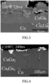
FIG. 1 , in actual practice, after a period of time and under high temperature, copper can still react with gallium to form a needle-like intermetallic compound CuGa, which is also known as liquid metal dry-out. This kind of intermetallic compound will continue to accumulate and thicken under long term use, as shown inFIGS. 2 to 4 , and finally cause the liquid metal to lose its thermal and electrical conductivity. Further, if the liquid metal comes into contact with an electronic component or substrate, it is also easy to cause short circuit damage. -
CN211982421U discloses a heat dissipation device including a heat sink, and a liquid metal layer arranged between the heat source and the heat sink, and the heat sink includes a sheet body facing the heat source, and an anti-corrosion metal layer plated on the sheet body. The liquid metal layer is attached to the anti-corrosion metal layer of the heat sink.WO2020162417 discloses a structure in which a metal having fluidity is utilized as a heat conductive material. In this structure, a heat conductive material is prevented from invading an unintended region even when a positional change of a semiconductor device occurs or a vibration occurs. - Therefore, an object of the present disclosure is to provide an electronic device that adopts a heat dissipation structure and that can alleviate at least one of the drawbacks of the prior art.
- According to the present disclosure, there is provided an electronic device that includes a heat-generating structure and a heat dissipation structure. The heat-generating structure includes a substrate, an electronic component disposed on the substrate, and at least one electronic element disposed on the substrate and spaced apart from the electronic component. The heat dissipation structure includes a heat dissipation unit, a liquid metal layer, a blocking member, a fixing adhesive, an insulation layer, and a cushioning adhesive. The heat dissipation unit includes a heat dissipation body and an anti-corrosion layer formed on the heat dissipation body. The liquid metal layer is disposed between the electronic component and the heat dissipation body, and abuts against the anti-corrosion layer. The blocking member is disposed between the substrate and the anti-corrosion layer, is connected to the substrate, and surrounds the liquid metal layer and the electronic component. The fixing adhesive is disposed on the substrate, and is located between the electronic component and the blocking member. The insulation layer is disposed between the substrate and the anti-corrosion layer. The cushioning adhesive is disposed between the blocking member and the anti-corrosion layer. An insulation glue is disposed between said insulation layer and said substrate and encapsulating said at least one electronic element, wherein said insulation layer extends from said blocking member to said fixing adhesive and covers said insulation glue, and said cushioning adhesive is clamped between said insulation layer and said anti-corrosion layer.
- Other features and advantages of the disclosure will become apparent in the following detailed description of the embodiments with reference to the accompanying drawings, of which:
-
FIG. 1 is a scanning electron microscope (SEM) image of a crystalline phase of a needle-like copper-gallium compound; -
FIGS. 2 to 4 illustrate an accumulation process of the copper-gallium compound; -
FIG. 5 is a sectional view of a first embodiment of an electronic device according to the present disclosure; -
FIG. 6 is a fragmentary top view of the first embodiment; -
FIG. 7 is a view similar toFIG. 5 , but illustrating how the first embodiment can prevent a liquid metal layer from contacting electronic elements or a substrate; -
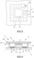
FIG. 8 is a fragmentary top view of a second embodiment of the electronic device according to the present disclosure; and -
FIG. 9 is a sectional view of a third embodiment of the electronic device according to the present disclosure. - Before the disclosure is described in greater detail, it should be noted that where considered appropriate, reference numerals or terminal portions of reference numerals have been repeated among the figures to indicate corresponding or analogous elements, which may optionally have similar characteristics.
- Referring to
FIGS. 5 and 6 , a first embodiment of anelectronic device 3 according to the present disclosure includes a heat-generating structure 2, and aheat dissipation structure 1 for dissipating heat from the heat-generating structure 2. - The heat-
generating structure 2 includes asubstrate 21, anelectronic component 22 disposed on thesubstrate 21, and a plurality ofelectronic elements 23 disposed on thesubstrate 1 and spaced apart from theelectronic component 22. The heat-generating structure 2 may be, for example, but not limited to, a central processing unit (CPU) or a graphics processing unit (GPU). Thesubstrate 21 includes a printedcircuit layer 211 located on top thereof, but is not limited thereto. Theelectronic elements 23 may be capacitors or other components. - The
heat dissipation structure 1 includes aliquid metal layer 11, aheat dissipation unit 12, a blockingmember 13, afixing adhesive 15, aninsulation layer 14, and acushioning adhesive 16. - The
heat dissipation unit 12 includes aheat dissipation body 121 parallel to thesubstrate 21, and ananti-corrosion layer 122 formed on theheat dissipation body 121. Theliquid metal layer 11 is disposed between theelectronic component 22 and theheat dissipation body 121, and abuts against theanti-corrosion layer 122. In this embodiment, theliquid metal layer 11 is coated on theelectronic component 22, but is not limited thereto. Theliquid metal layer 11 may be coated on theanti-corrosion layer 122 or on both of theelectronic component 22 and theanti-corrosion layer 122, as long as theliquid metal layer 11 is disposed between the heat-generating structure 2 and theheat dissipation unit 12. Theheat dissipation body 121 may be made of, but not limited to, copper, aluminum, and alloys thereof. Theanti-corrosion layer 122 may be made of, for example, one of a metallic material including nickel plated metal, gold, electroless nickel electroless palladium immersion gold (ENEPIG), silver, and stainless steel, or one of a non-metallic material including graphite and ceramic. - The blocking
member 13 is disposed between thesubstrate 21 and theanti-corrosion layer 122, is connected to thesubstrate 21, and surrounds and is spaced apart from theelectronic component 22. The blockingmember 13 may be connected to thesubstrate 21 by adhesion, latching, or integrally forming with thesubstrate 21. Theelectronic elements 23 are disposed between theelectronic component 22 and theblocking member 13. Thefixing adhesive 15 is disposed on thesubstrate 21, and is located between theelectronic component 22 and the blockingmember 13. Thefixing adhesive 15 may be, for example, a single-sided adhesive, a double-sided adhesive, or other polymeric materials. - The
insulation layer 14 is disposed between thesubstrate 21 and theanti-corrosion layer 122. In this embodiment, theinsulation layer 14 extends from the blockingmember 13 to thefixing adhesive 15, and covers theelectronic elements 23. Specifically, theinsulation layer 14 has an outer peripheral edge clamped between the blockingmember 13 and the cushioning adhesive 16, and an inner peripheral edge connected to an outer surface of theelectronic component 22 and abutting against a top side of thefixing adhesive 15. Theinsulation layer 14 is a polymeric material, and may be provided with a single-sided adhesive at a side facing thesubstrate 21. - The
cushioning adhesive 16 is disposed between the blockingmember 13 and theanti-corrosion layer 122. Specifically, the cushioning adhesive 16 of this embodiment is clamped between theinsulation layer 14 and theanti-corrosion layer 122. - It should be noted herein that, in this embodiment, an
insulation glue 17 is disposed between theinsulation layer 14 and thesubstrate 21 to enhance the insulating effect. Theinsulation glue 17 encapsulates theelectronic elements 23, and can be adhered to theinsulation layer 14 or thesubstrate 21. - The
anti-corrosion layer 122 is disposed between theheat dissipation body 121 and theliquid metal layer 11 to prevent theliquid metal layer 11 from directly contacting theheat dissipation body 121 during heat dissipation, thereby preventing theheat dissipation body 121 from being corroded by theliquid metal layer 11 or forming an intermetallic compound therewith. Thus, damage of theheat dissipation body 121 can be avoided, and the heat dissipation stability of theliquid metal layer 11 can be ensured. - In this embodiment, the
fixing adhesive 15 has a square shape, and surrounds theelectronic component 22, as shown inFIG. 6 . Specifically, thefixing adhesive 15 is located between theelectronic elements 23 and theelectronic component 22, and has an upper surface adhered to theinsulation layer 14 and a lower surface adhered to thesubstrate 21. Theinsulation layer 14 is of insulating material, has the inner and outer peripheral edges respectively adhered to thefixing adhesive 15 and the blockingmember 13, and is located above theelectronic elements 23 in order to cover the same. In some other embodiments, the outer peripheral edge of theinsulation layer 14 may be directly disposed on thesubstrate 21 instead of being connected to the blockingmember 13. - The cushioning
adhesive 16 is made of a polymeric material. In this embodiment, the cushioningadhesive 16 is a foam tape, and may be located above the blockingmember 13 or between an inner side of the blockingmember 13 and theelectronic component 22. The cushioningadhesive 16 has a lower surface adhered to the outer peripheral edge of theinsulation layer 14 and an upper surface adhered to theanti-corrosion layer 122. In some other embodiments, the cushioningadhesive 16 may not be adhered to theanti-corrosion layer 122, but is directly pressed on theanti-corrosion layer 122. - Referring to
FIG. 7 , in combination withFIGS. 5 and 6 , due to the fluidity of theliquid metal layer 11, theliquid metal layer 11 may flow onto thesubstrate 21. Through the blocking of the fixingadhesive 15 and theinsulation layer 14, theliquid metal layer 11 can be prevented from contacting theelectronic elements 23 and thesubstrate 21, thereby avoiding short circuiting or corroding of other components. The blockingmember 13 can block and prevent theliquid metal layer 11 from overflowing to a motherboard which can cause short circuit and corrosion problems. Further, a user may adhere the fixingadhesive 15, theinsulation layer 14, the blockingmember 13, and thecushioning adhesive 16 on the heat-generatingstructure 2 by himself or herself according to the different configurations of the heat-generatingstructure 2, so that they are suitable to be used in a heat-generatingstructure 2 that is commercially available in the market. Thus, the versatility of this disclosure can be improved. - Referring to
FIG. 8 , a second embodiment of theelectronic device 3 of this disclosure is substantially the same as the first embodiment, except that, in the second embodiment, the fixingadhesive 15 is spaced apart from theelectronic component 22 to form aspace 171 therebetween, and has anopening 172 for communicating thespace 171 with an external environment. That is, the fixingadhesive 15 has a square shape with a missing corner and surrounds theelectronic component 22. When an automated production of theelectronic device 3 is performed and theheat dissipation unit 12 is quickly covered on theliquid metal layer 11, air that enters thespace 171 along with theheat dissipation unit 12 can be dissipated to the external environment through theopening 172, thereby preventing short circuiting and/or corroding of theelectronic elements 23 after theheat dissipation unit 12 is adhered to theinsulation glue 17. Without the presence of theopening 172, after theheat dissipation unit 12 is adhered to theinsulation glue 17, air in thespace 171 has nowhere to escape, causing liquid metal to spatter onto theelectronic elements 23, thereby short circuiting and/or corroding theelectronic elements 23. To be noted is that, theinsulation glue 17 is an insulating glue that can be dispensed using an automatic dispenser. - Referring to
FIG. 9 , a third embodiment of theelectronic device 3 according to the present disclosure is substantially the same as the first embodiment, except that, in the third embodiment, theelectronic elements 23 are embedded in thesubstrate 21 and are located below theinsulation layer 14 and the fixingadhesive 15. Further, the outer peripheral edge of theinsulation layer 14 abuts against the blockingmember 13, and the inner peripheral edge thereof abuts against the fixingadhesive 15. Moreover, the blockingmember 13 surrounds theliquid metal layer 11, and thecushioning adhesive 16 is disposed and clamped between the blockingmember 13 and theanti-corrosion layer 122. - In summary, by forming an
anti-corrosion layer 122 on theheat dissipation body 121 of theheat dissipation unit 12, theanti-corrosion layer 122 can prevent direct contact between theliquid metal layer 11 and theheat dissipation body 121, so that reaction and corrosion between the two can be avoided, thereby improving stability and durability of theheat dissipation structure 1 of this disclosure. Moreover, theinsulation layer 14 and the fixingadhesive 15 can cover theelectronic elements 23 to prevent them from short circuiting due to contact with theliquid metal layer 11. In addition, theopening 172 can dissipate air in thespace 171 to the external environment, thereby preventing the air from affecting theliquid metal layer 11 and spattering of liquid metal onto theelectronic elements 23, which can cause short circuiting and/or corroding thereof. Therefore, this disclosure can adapt to rapid automated manufacturing processes.
Claims (10)
- An electronic device (3), characterized by:a heat-generating structure (2) including a substrate (21), an electronic component (22) disposed on said substrate (21), and at least one electronic element (23) disposed on said substrate (21) and spaced apart from said electronic component (22);a heat dissipation structure (1) including:a heat dissipation unit (12) that includes a heat dissipation body (121) and an anti-corrosion layer (122) formed on said heat dissipation body (121),a liquid metal layer (11) disposed between said electronic component (22) and said heat dissipation body (121) and abutting against said anti-corrosion layer (122),a blocking member (13) that is disposed between said substrate (21) and said anti-corrosion layer (122), that is connected to said substrate (21), and that surrounds said liquid metal layer (11) and said electronic component (22),a fixing adhesive (15) that is disposed on said substrate (21) and that is located between said electronic component (22) and said blocking member (13),an insulation layer (14) disposed between said substrate (21) and said anti-corrosion layer (122); characterized bya cushioning adhesive (16) disposed between said blocking member (13) and said anti-corrosion layer (122); andan insulation glue (17) disposed between said insulation layer (14) and said substrate (21) and encapsulating said at least one electronic element (23);wherein said insulation layer (14) extends from said blocking member (13) to said fixing adhesive (15) and covers said insulation glue (17), and said cushioning adhesive (16) is clamped between said insulation layer (14) and said anti-corrosion layer (122) .
- The electronic device (3) as claimed in claim 1, characterized in that said anti-corrosion layer (122) is made of one of nickel plated metal, gold, electroless nickel electroless palladium immersion gold, silver, stainless steel, graphite, and ceramic.
- The electronic device (3) as claimed in claims 1 or 2, characterized in that said at least one electronic element (23) is disposed between said electronic component (22) and said blocking member (13) .
- The electronic device (3) as claimed in any one of claims 1 to 3, characterized in that an outer peripheral edge of said insulation layer (14) is clamped between said blocking member (13) and said cushioning adhesive (16).
- The electronic device (3) as claimed in any one of claims 1 to 4, characterized in that said fixing adhesive (15) is spaced apart from said electronic component (22) to form a space (171) therebetween and has an opening (172) for communicating said space (171) with an external environment.
- The electronic device (3) as claimed in any one of claims 1 to 5, characterized in that said fixing adhesive (15) is one of a single-sided adhesive, a double-sided adhesive, and a polymeric material.
- The electronic device (3) as claimed in any one of claims 1 to 6, characterized in that said cushioning adhesive (16) is made of a polymeric material.
- The electronic device (3) as claimed in claim 7, characterized in that said cushioning adhesive (16) is a foam tape.
- The electronic device (3) as claimed in any one of claims 1 to 8, characterized in that said insulation layer (14) is a polymeric material.
- The electronic device (3) as claimed in any one of claims 1 to 9, characterized in that said insulation layer (14) is provided with a single-sided adhesive at a side facing said substrate (21).
Priority Applications (2)
| Application Number | Priority Date | Filing Date | Title |
|---|---|---|---|
| DK23154949.4T DK4199073T3 (en) | 2021-03-09 | 2022-01-19 | ELECTRONIC DEVICE ADOPTING HEAT DISSIPATION STRUCTURE |
| EP23154949.4A EP4199073B1 (en) | 2021-03-09 | 2022-01-19 | Electronic device adopting heat dissipation structure |
Applications Claiming Priority (1)
| Application Number | Priority Date | Filing Date | Title |
|---|---|---|---|
| TW110202467U TWM613290U (en) | 2021-03-09 | 2021-03-09 | Heat dissipation apparatus |
Related Child Applications (2)
| Application Number | Title | Priority Date | Filing Date |
|---|---|---|---|
| EP23154949.4A Division-Into EP4199073B1 (en) | 2021-03-09 | 2022-01-19 | Electronic device adopting heat dissipation structure |
| EP23154949.4A Division EP4199073B1 (en) | 2021-03-09 | 2022-01-19 | Electronic device adopting heat dissipation structure |
Publications (2)
| Publication Number | Publication Date |
|---|---|
| EP4057337A1 EP4057337A1 (en) | 2022-09-14 |
| EP4057337B1 true EP4057337B1 (en) | 2024-08-28 |
Family
ID=77517951
Family Applications (2)
| Application Number | Title | Priority Date | Filing Date |
|---|---|---|---|
| EP23154949.4A Active EP4199073B1 (en) | 2021-03-09 | 2022-01-19 | Electronic device adopting heat dissipation structure |
| EP22152268.3A Active EP4057337B1 (en) | 2021-03-09 | 2022-01-19 | Electronic device adopting heat dissipation structure |
Family Applications Before (1)
| Application Number | Title | Priority Date | Filing Date |
|---|---|---|---|
| EP23154949.4A Active EP4199073B1 (en) | 2021-03-09 | 2022-01-19 | Electronic device adopting heat dissipation structure |
Country Status (3)
| Country | Link |
|---|---|
| EP (2) | EP4199073B1 (en) |
| DK (2) | DK4057337T3 (en) |
| TW (1) | TWM613290U (en) |
Families Citing this family (3)
| Publication number | Priority date | Publication date | Assignee | Title |
|---|---|---|---|---|
| CN113889444B (en) * | 2021-09-13 | 2023-04-28 | 云南中宣液态金属科技有限公司 | Packaging structure and packaging method of circuit board containing liquid metal and circuit board |
| CN216749870U (en) * | 2021-12-10 | 2022-06-14 | 云南中宣液态金属科技有限公司 | Liquid metal packaging structure for chip heat dissipation |
| TWI863204B (en) * | 2023-03-31 | 2024-11-21 | 裕晨科技股份有限公司 | Semiconductor devices |
Family Cites Families (3)
| Publication number | Priority date | Publication date | Assignee | Title |
|---|---|---|---|---|
| KR100245971B1 (en) * | 1995-11-30 | 2000-03-02 | 포만 제프리 엘 | Heat sink assembly using adhesion promoting layer for bonding polymeric adhesive to metal and the method of making the same |
| EP3923317A4 (en) * | 2019-02-04 | 2022-11-30 | Sony Interactive Entertainment Inc. | ELECTRONIC APPARATUS, SEMICONDUCTOR DEVICE, INSULATION SHEET, AND SEMICONDUCTOR DEVICE MANUFACTURING METHOD |
| CN211982421U (en) * | 2020-06-08 | 2020-11-20 | 裕晨科技股份有限公司 | heat sink |
-
2021
- 2021-03-09 TW TW110202467U patent/TWM613290U/en unknown
-
2022
- 2022-01-19 EP EP23154949.4A patent/EP4199073B1/en active Active
- 2022-01-19 EP EP22152268.3A patent/EP4057337B1/en active Active
- 2022-01-19 DK DK22152268.3T patent/DK4057337T3/en active
- 2022-01-19 DK DK23154949.4T patent/DK4199073T3/en active
Also Published As
| Publication number | Publication date |
|---|---|
| EP4057337A1 (en) | 2022-09-14 |
| TWM613290U (en) | 2021-06-11 |
| EP4199073B1 (en) | 2024-08-07 |
| EP4199073A1 (en) | 2023-06-21 |
| DK4057337T3 (en) | 2024-09-23 |
| DK4199073T3 (en) | 2024-09-02 |
Similar Documents
| Publication | Publication Date | Title |
|---|---|---|
| US11758691B2 (en) | Heat dissipation structure and electronic device adopting the same | |
| EP4199073B1 (en) | Electronic device adopting heat dissipation structure | |
| CN104718615B (en) | Semiconductor circuit board and its manufacture method and use its semiconductor device | |
| CN100589243C (en) | Semiconductor device | |
| JP6797797B2 (en) | Ceramic metal circuit board and semiconductor device using it | |
| US7440281B2 (en) | Thermal interface apparatus | |
| KR102027615B1 (en) | Power module substrate with heat sink, power module substrate with cooler, and power module | |
| JP7483955B2 (en) | Power module substrate and power module | |
| JP2006240955A (en) | Ceramic substrate, ceramic circuit substrate and power control component using the same. | |
| JP4683043B2 (en) | Manufacturing method of semiconductor device | |
| JP2004356625A (en) | Semiconductor device and manufacturing method thereof | |
| CN211982421U (en) | heat sink | |
| KR20100126284A (en) | Heat sink formation method | |
| JP5087048B2 (en) | Circuit board with integrated heat dissipation components | |
| TWM615231U (en) | Heat dissipation structure | |
| JP6011410B2 (en) | Semiconductor device assembly, power module substrate and power module | |
| JPS5819385B2 (en) | Rouzukehouhou | |
| CN110429070B (en) | Power components with double-sided heat dissipation | |
| JP2006351988A (en) | Ceramic substrate, ceramic circuit substrate and power control component using the same. | |
| CN214504361U (en) | heat sink | |
| EP4439656B1 (en) | Semiconductor device | |
| CN224250153U (en) | Chip packaging structure and circuit board | |
| CN223786515U (en) | Packaging structure | |
| JP4160026B2 (en) | Heat dissipation body for electrical parts | |
| CN215121667U (en) | Heat radiation structure |
Legal Events
| Date | Code | Title | Description |
|---|---|---|---|
| PUAI | Public reference made under article 153(3) epc to a published international application that has entered the european phase |
Free format text: ORIGINAL CODE: 0009012 |
|
| STAA | Information on the status of an ep patent application or granted ep patent |
Free format text: STATUS: THE APPLICATION HAS BEEN PUBLISHED |
|
| AK | Designated contracting states |
Kind code of ref document: A1 Designated state(s): AL AT BE BG CH CY CZ DE DK EE ES FI FR GB GR HR HU IE IS IT LI LT LU LV MC MK MT NL NO PL PT RO RS SE SI SK SM TR |
|
| STAA | Information on the status of an ep patent application or granted ep patent |
Free format text: STATUS: REQUEST FOR EXAMINATION WAS MADE |
|
| 17P | Request for examination filed |
Effective date: 20230307 |
|
| RBV | Designated contracting states (corrected) |
Designated state(s): AL AT BE BG CH CY CZ DE DK EE ES FI FR GB GR HR HU IE IS IT LI LT LU LV MC MK MT NL NO PL PT RO RS SE SI SK SM TR |
|
| RAP1 | Party data changed (applicant data changed or rights of an application transferred) |
Owner name: WINCHAIN MATERIAL TECHNOLOGY CO., LTD. |
|
| GRAP | Despatch of communication of intention to grant a patent |
Free format text: ORIGINAL CODE: EPIDOSNIGR1 |
|
| STAA | Information on the status of an ep patent application or granted ep patent |
Free format text: STATUS: GRANT OF PATENT IS INTENDED |
|
| INTG | Intention to grant announced |
Effective date: 20240321 |
|
| RIN1 | Information on inventor provided before grant (corrected) |
Inventor name: LIN, CHIU-LANG |
|
| GRAS | Grant fee paid |
Free format text: ORIGINAL CODE: EPIDOSNIGR3 |
|
| GRAA | (expected) grant |
Free format text: ORIGINAL CODE: 0009210 |
|
| STAA | Information on the status of an ep patent application or granted ep patent |
Free format text: STATUS: THE PATENT HAS BEEN GRANTED |
|
| P01 | Opt-out of the competence of the unified patent court (upc) registered |
Free format text: CASE NUMBER: APP_41313/2024 Effective date: 20240712 |
|
| AK | Designated contracting states |
Kind code of ref document: B1 Designated state(s): AL AT BE BG CH CY CZ DE DK EE ES FI FR GB GR HR HU IE IS IT LI LT LU LV MC MK MT NL NO PL PT RO RS SE SI SK SM TR |
|
| REG | Reference to a national code |
Ref country code: CH Ref legal event code: EP |
|
| REG | Reference to a national code |
Ref country code: DE Ref legal event code: R096 Ref document number: 602022005554 Country of ref document: DE |
|
| REG | Reference to a national code |
Ref country code: DK Ref legal event code: T3 Effective date: 20240917 |
|
| REG | Reference to a national code |
Ref country code: IE Ref legal event code: FG4D |
|
| REG | Reference to a national code |
Ref country code: SE Ref legal event code: TRGR |
|
| REG | Reference to a national code |
Ref country code: NL Ref legal event code: FP |
|
| REG | Reference to a national code |
Ref country code: LT Ref legal event code: MG9D |
|
| PG25 | Lapsed in a contracting state [announced via postgrant information from national office to epo] |
Ref country code: NO Free format text: LAPSE BECAUSE OF FAILURE TO SUBMIT A TRANSLATION OF THE DESCRIPTION OR TO PAY THE FEE WITHIN THE PRESCRIBED TIME-LIMIT Effective date: 20241128 |
|
| REG | Reference to a national code |
Ref country code: AT Ref legal event code: MK05 Ref document number: 1718964 Country of ref document: AT Kind code of ref document: T Effective date: 20240828 |
|
| PG25 | Lapsed in a contracting state [announced via postgrant information from national office to epo] |
Ref country code: FI Free format text: LAPSE BECAUSE OF FAILURE TO SUBMIT A TRANSLATION OF THE DESCRIPTION OR TO PAY THE FEE WITHIN THE PRESCRIBED TIME-LIMIT Effective date: 20240828 Ref country code: PL Free format text: LAPSE BECAUSE OF FAILURE TO SUBMIT A TRANSLATION OF THE DESCRIPTION OR TO PAY THE FEE WITHIN THE PRESCRIBED TIME-LIMIT Effective date: 20240828 Ref country code: PT Free format text: LAPSE BECAUSE OF FAILURE TO SUBMIT A TRANSLATION OF THE DESCRIPTION OR TO PAY THE FEE WITHIN THE PRESCRIBED TIME-LIMIT Effective date: 20241230 Ref country code: GR Free format text: LAPSE BECAUSE OF FAILURE TO SUBMIT A TRANSLATION OF THE DESCRIPTION OR TO PAY THE FEE WITHIN THE PRESCRIBED TIME-LIMIT Effective date: 20241129 |
|
| PG25 | Lapsed in a contracting state [announced via postgrant information from national office to epo] |
Ref country code: BG Free format text: LAPSE BECAUSE OF FAILURE TO SUBMIT A TRANSLATION OF THE DESCRIPTION OR TO PAY THE FEE WITHIN THE PRESCRIBED TIME-LIMIT Effective date: 20240828 |
|
| PG25 | Lapsed in a contracting state [announced via postgrant information from national office to epo] |
Ref country code: LV Free format text: LAPSE BECAUSE OF FAILURE TO SUBMIT A TRANSLATION OF THE DESCRIPTION OR TO PAY THE FEE WITHIN THE PRESCRIBED TIME-LIMIT Effective date: 20240828 |
|
| PG25 | Lapsed in a contracting state [announced via postgrant information from national office to epo] |
Ref country code: AT Free format text: LAPSE BECAUSE OF FAILURE TO SUBMIT A TRANSLATION OF THE DESCRIPTION OR TO PAY THE FEE WITHIN THE PRESCRIBED TIME-LIMIT Effective date: 20240828 Ref country code: IS Free format text: LAPSE BECAUSE OF FAILURE TO SUBMIT A TRANSLATION OF THE DESCRIPTION OR TO PAY THE FEE WITHIN THE PRESCRIBED TIME-LIMIT Effective date: 20241228 |
|
| PG25 | Lapsed in a contracting state [announced via postgrant information from national office to epo] |
Ref country code: HR Free format text: LAPSE BECAUSE OF FAILURE TO SUBMIT A TRANSLATION OF THE DESCRIPTION OR TO PAY THE FEE WITHIN THE PRESCRIBED TIME-LIMIT Effective date: 20240828 |
|
| PG25 | Lapsed in a contracting state [announced via postgrant information from national office to epo] |
Ref country code: RS Free format text: LAPSE BECAUSE OF FAILURE TO SUBMIT A TRANSLATION OF THE DESCRIPTION OR TO PAY THE FEE WITHIN THE PRESCRIBED TIME-LIMIT Effective date: 20241128 Ref country code: ES Free format text: LAPSE BECAUSE OF FAILURE TO SUBMIT A TRANSLATION OF THE DESCRIPTION OR TO PAY THE FEE WITHIN THE PRESCRIBED TIME-LIMIT Effective date: 20240828 |
|
| PG25 | Lapsed in a contracting state [announced via postgrant information from national office to epo] |
Ref country code: RS Free format text: LAPSE BECAUSE OF FAILURE TO SUBMIT A TRANSLATION OF THE DESCRIPTION OR TO PAY THE FEE WITHIN THE PRESCRIBED TIME-LIMIT Effective date: 20241128 Ref country code: PT Free format text: LAPSE BECAUSE OF FAILURE TO SUBMIT A TRANSLATION OF THE DESCRIPTION OR TO PAY THE FEE WITHIN THE PRESCRIBED TIME-LIMIT Effective date: 20241230 Ref country code: PL Free format text: LAPSE BECAUSE OF FAILURE TO SUBMIT A TRANSLATION OF THE DESCRIPTION OR TO PAY THE FEE WITHIN THE PRESCRIBED TIME-LIMIT Effective date: 20240828 Ref country code: NO Free format text: LAPSE BECAUSE OF FAILURE TO SUBMIT A TRANSLATION OF THE DESCRIPTION OR TO PAY THE FEE WITHIN THE PRESCRIBED TIME-LIMIT Effective date: 20241128 Ref country code: LV Free format text: LAPSE BECAUSE OF FAILURE TO SUBMIT A TRANSLATION OF THE DESCRIPTION OR TO PAY THE FEE WITHIN THE PRESCRIBED TIME-LIMIT Effective date: 20240828 Ref country code: IS Free format text: LAPSE BECAUSE OF FAILURE TO SUBMIT A TRANSLATION OF THE DESCRIPTION OR TO PAY THE FEE WITHIN THE PRESCRIBED TIME-LIMIT Effective date: 20241228 Ref country code: HR Free format text: LAPSE BECAUSE OF FAILURE TO SUBMIT A TRANSLATION OF THE DESCRIPTION OR TO PAY THE FEE WITHIN THE PRESCRIBED TIME-LIMIT Effective date: 20240828 Ref country code: GR Free format text: LAPSE BECAUSE OF FAILURE TO SUBMIT A TRANSLATION OF THE DESCRIPTION OR TO PAY THE FEE WITHIN THE PRESCRIBED TIME-LIMIT Effective date: 20241129 Ref country code: FI Free format text: LAPSE BECAUSE OF FAILURE TO SUBMIT A TRANSLATION OF THE DESCRIPTION OR TO PAY THE FEE WITHIN THE PRESCRIBED TIME-LIMIT Effective date: 20240828 Ref country code: ES Free format text: LAPSE BECAUSE OF FAILURE TO SUBMIT A TRANSLATION OF THE DESCRIPTION OR TO PAY THE FEE WITHIN THE PRESCRIBED TIME-LIMIT Effective date: 20240828 Ref country code: BG Free format text: LAPSE BECAUSE OF FAILURE TO SUBMIT A TRANSLATION OF THE DESCRIPTION OR TO PAY THE FEE WITHIN THE PRESCRIBED TIME-LIMIT Effective date: 20240828 Ref country code: AT Free format text: LAPSE BECAUSE OF FAILURE TO SUBMIT A TRANSLATION OF THE DESCRIPTION OR TO PAY THE FEE WITHIN THE PRESCRIBED TIME-LIMIT Effective date: 20240828 |
|
| PG25 | Lapsed in a contracting state [announced via postgrant information from national office to epo] |
Ref country code: SM Free format text: LAPSE BECAUSE OF FAILURE TO SUBMIT A TRANSLATION OF THE DESCRIPTION OR TO PAY THE FEE WITHIN THE PRESCRIBED TIME-LIMIT Effective date: 20240828 Ref country code: RO Free format text: LAPSE BECAUSE OF FAILURE TO SUBMIT A TRANSLATION OF THE DESCRIPTION OR TO PAY THE FEE WITHIN THE PRESCRIBED TIME-LIMIT Effective date: 20240828 |
|
| PG25 | Lapsed in a contracting state [announced via postgrant information from national office to epo] |
Ref country code: EE Free format text: LAPSE BECAUSE OF FAILURE TO SUBMIT A TRANSLATION OF THE DESCRIPTION OR TO PAY THE FEE WITHIN THE PRESCRIBED TIME-LIMIT Effective date: 20240828 |
|
| PG25 | Lapsed in a contracting state [announced via postgrant information from national office to epo] |
Ref country code: SK Free format text: LAPSE BECAUSE OF FAILURE TO SUBMIT A TRANSLATION OF THE DESCRIPTION OR TO PAY THE FEE WITHIN THE PRESCRIBED TIME-LIMIT Effective date: 20240828 |
|
| REG | Reference to a national code |
Ref country code: DE Ref legal event code: R097 Ref document number: 602022005554 Country of ref document: DE |
|
| PLBE | No opposition filed within time limit |
Free format text: ORIGINAL CODE: 0009261 |
|
| STAA | Information on the status of an ep patent application or granted ep patent |
Free format text: STATUS: NO OPPOSITION FILED WITHIN TIME LIMIT |
|
| 26N | No opposition filed |
Effective date: 20250530 |
|
| PG25 | Lapsed in a contracting state [announced via postgrant information from national office to epo] |
Ref country code: MC Free format text: LAPSE BECAUSE OF FAILURE TO SUBMIT A TRANSLATION OF THE DESCRIPTION OR TO PAY THE FEE WITHIN THE PRESCRIBED TIME-LIMIT Effective date: 20240828 Ref country code: LU Free format text: LAPSE BECAUSE OF NON-PAYMENT OF DUE FEES Effective date: 20250119 |
|
| REG | Reference to a national code |
Ref country code: DE Ref legal event code: R079 Ref document number: 602022005554 Country of ref document: DE Free format text: PREVIOUS MAIN CLASS: H01L0023360000 Ipc: H10W0040200000 |
|
| PG25 | Lapsed in a contracting state [announced via postgrant information from national office to epo] |
Ref country code: IE Free format text: LAPSE BECAUSE OF NON-PAYMENT OF DUE FEES Effective date: 20250119 |
|
| REG | Reference to a national code |
Ref country code: CH Ref legal event code: U11 Free format text: ST27 STATUS EVENT CODE: U-0-0-U10-U11 (AS PROVIDED BY THE NATIONAL OFFICE) Effective date: 20260201 |
|
| PGFP | Annual fee paid to national office [announced via postgrant information from national office to epo] |
Ref country code: NL Payment date: 20260122 Year of fee payment: 5 |
|
| PGFP | Annual fee paid to national office [announced via postgrant information from national office to epo] |
Ref country code: SE Payment date: 20260112 Year of fee payment: 5 |
|
| PGFP | Annual fee paid to national office [announced via postgrant information from national office to epo] |
Ref country code: GB Payment date: 20260119 Year of fee payment: 5 |
|
| PGFP | Annual fee paid to national office [announced via postgrant information from national office to epo] |
Ref country code: DK Payment date: 20260123 Year of fee payment: 5 Ref country code: DE Payment date: 20260115 Year of fee payment: 5 |
|
| PGFP | Annual fee paid to national office [announced via postgrant information from national office to epo] |
Ref country code: BE Payment date: 20260123 Year of fee payment: 5 Ref country code: IT Payment date: 20260122 Year of fee payment: 5 |
|
| PGFP | Annual fee paid to national office [announced via postgrant information from national office to epo] |
Ref country code: FR Payment date: 20260115 Year of fee payment: 5 |
|
| PGFP | Annual fee paid to national office [announced via postgrant information from national office to epo] |
Ref country code: TR Payment date: 20260114 Year of fee payment: 5 |
|
| PGFP | Annual fee paid to national office [announced via postgrant information from national office to epo] |
Ref country code: CZ Payment date: 20260114 Year of fee payment: 5 Ref country code: CH Payment date: 20260201 Year of fee payment: 5 |