EP4056986A1 - Wiring structure, conductive particle detecting device, and speed reducer - Google Patents
Wiring structure, conductive particle detecting device, and speed reducer Download PDFInfo
- Publication number
- EP4056986A1 EP4056986A1 EP22160550.4A EP22160550A EP4056986A1 EP 4056986 A1 EP4056986 A1 EP 4056986A1 EP 22160550 A EP22160550 A EP 22160550A EP 4056986 A1 EP4056986 A1 EP 4056986A1
- Authority
- EP
- European Patent Office
- Prior art keywords
- conductive
- permanent magnets
- flexible printed
- relay
- printed wiring
- Prior art date
- Legal status (The legal status is an assumption and is not a legal conclusion. Google has not performed a legal analysis and makes no representation as to the accuracy of the status listed.)
- Granted
Links
Images



Classifications
-
- G—PHYSICS
- G01—MEASURING; TESTING
- G01N—INVESTIGATING OR ANALYSING MATERIALS BY DETERMINING THEIR CHEMICAL OR PHYSICAL PROPERTIES
- G01N27/00—Investigating or analysing materials by the use of electric, electrochemical, or magnetic means
- G01N27/02—Investigating or analysing materials by the use of electric, electrochemical, or magnetic means by investigating impedance
- G01N27/04—Investigating or analysing materials by the use of electric, electrochemical, or magnetic means by investigating impedance by investigating resistance
- G01N27/043—Investigating or analysing materials by the use of electric, electrochemical, or magnetic means by investigating impedance by investigating resistance of a granular material
-
- F—MECHANICAL ENGINEERING; LIGHTING; HEATING; WEAPONS; BLASTING
- F16—ENGINEERING ELEMENTS AND UNITS; GENERAL MEASURES FOR PRODUCING AND MAINTAINING EFFECTIVE FUNCTIONING OF MACHINES OR INSTALLATIONS; THERMAL INSULATION IN GENERAL
- F16H—GEARING
- F16H57/00—General details of gearing
- F16H57/04—Features relating to lubrication or cooling or heating
- F16H57/0405—Monitoring quality of lubricant or hydraulic fluids
-
- G—PHYSICS
- G01—MEASURING; TESTING
- G01N—INVESTIGATING OR ANALYSING MATERIALS BY DETERMINING THEIR CHEMICAL OR PHYSICAL PROPERTIES
- G01N15/00—Investigating characteristics of particles; Investigating permeability, pore-volume or surface-area of porous materials
- G01N15/06—Investigating concentration of particle suspensions
- G01N15/0656—Investigating concentration of particle suspensions using electric, e.g. electrostatic methods or magnetic methods
-
- G—PHYSICS
- G01—MEASURING; TESTING
- G01N—INVESTIGATING OR ANALYSING MATERIALS BY DETERMINING THEIR CHEMICAL OR PHYSICAL PROPERTIES
- G01N27/00—Investigating or analysing materials by the use of electric, electrochemical, or magnetic means
- G01N27/02—Investigating or analysing materials by the use of electric, electrochemical, or magnetic means by investigating impedance
- G01N27/04—Investigating or analysing materials by the use of electric, electrochemical, or magnetic means by investigating impedance by investigating resistance
- G01N27/045—Circuits
-
- G—PHYSICS
- G01—MEASURING; TESTING
- G01N—INVESTIGATING OR ANALYSING MATERIALS BY DETERMINING THEIR CHEMICAL OR PHYSICAL PROPERTIES
- G01N27/00—Investigating or analysing materials by the use of electric, electrochemical, or magnetic means
- G01N27/02—Investigating or analysing materials by the use of electric, electrochemical, or magnetic means by investigating impedance
- G01N27/04—Investigating or analysing materials by the use of electric, electrochemical, or magnetic means by investigating impedance by investigating resistance
- G01N27/06—Investigating or analysing materials by the use of electric, electrochemical, or magnetic means by investigating impedance by investigating resistance of a liquid
- G01N27/07—Construction of measuring vessels; Electrodes therefor
-
- G—PHYSICS
- G01—MEASURING; TESTING
- G01N—INVESTIGATING OR ANALYSING MATERIALS BY DETERMINING THEIR CHEMICAL OR PHYSICAL PROPERTIES
- G01N33/00—Investigating or analysing materials by specific methods not covered by groups G01N1/00 - G01N31/00
- G01N33/26—Oils; Viscous liquids; Paints; Inks
- G01N33/28—Oils, i.e. hydrocarbon liquids
- G01N33/2835—Specific substances contained in the oils or fuels
- G01N33/2858—Metal particles
-
- H—ELECTRICITY
- H05—ELECTRIC TECHNIQUES NOT OTHERWISE PROVIDED FOR
- H05K—PRINTED CIRCUITS; CASINGS OR CONSTRUCTIONAL DETAILS OF ELECTRIC APPARATUS; MANUFACTURE OF ASSEMBLAGES OF ELECTRICAL COMPONENTS
- H05K1/00—Printed circuits
- H05K1/02—Details
- H05K1/0277—Bendability or stretchability details
-
- H—ELECTRICITY
- H05—ELECTRIC TECHNIQUES NOT OTHERWISE PROVIDED FOR
- H05K—PRINTED CIRCUITS; CASINGS OR CONSTRUCTIONAL DETAILS OF ELECTRIC APPARATUS; MANUFACTURE OF ASSEMBLAGES OF ELECTRICAL COMPONENTS
- H05K1/00—Printed circuits
- H05K1/18—Printed circuits structurally associated with non-printed electric components
-
- H—ELECTRICITY
- H01—ELECTRIC ELEMENTS
- H01F—MAGNETS; INDUCTANCES; TRANSFORMERS; SELECTION OF MATERIALS FOR THEIR MAGNETIC PROPERTIES
- H01F7/00—Magnets
- H01F7/02—Permanent magnets [PM]
-
- H—ELECTRICITY
- H05—ELECTRIC TECHNIQUES NOT OTHERWISE PROVIDED FOR
- H05K—PRINTED CIRCUITS; CASINGS OR CONSTRUCTIONAL DETAILS OF ELECTRIC APPARATUS; MANUFACTURE OF ASSEMBLAGES OF ELECTRICAL COMPONENTS
- H05K2201/00—Indexing scheme relating to printed circuits covered by H05K1/00
- H05K2201/10—Details of components or other objects attached to or integrated in a printed circuit board
- H05K2201/10007—Types of components
- H05K2201/10053—Switch
-
- H—ELECTRICITY
- H05—ELECTRIC TECHNIQUES NOT OTHERWISE PROVIDED FOR
- H05K—PRINTED CIRCUITS; CASINGS OR CONSTRUCTIONAL DETAILS OF ELECTRIC APPARATUS; MANUFACTURE OF ASSEMBLAGES OF ELECTRICAL COMPONENTS
- H05K2201/00—Indexing scheme relating to printed circuits covered by H05K1/00
- H05K2201/10—Details of components or other objects attached to or integrated in a printed circuit board
- H05K2201/10007—Types of components
- H05K2201/10151—Sensor
Definitions
- the present invention relates to a wiring structure, a conductive particle detecting device using the wiring structure, and a speed reducer using the conductive particle detecting device.
- a casing is filled with a lubricant to reduce the wear in the mechanism.
- metal powder is produced from mechanical parts.
- the metal powder produced from the mechanical parts mixes into the lubricant within the casing.
- the ability of the lubricant to inhibit the wear in the mechanism is reduced.
- the presence of the large amount of metal powder mixed into the lubricant indicates that the wear or damage has occurred in the mechanism.
- a device should preferably externally detect that the amount of the metal powder in the lubricant has exceeded a preset value.
- Devices for externally detecting the amount of the metal powder are disclosed (see, for example, Patent Literature 1). With these devices, the metal powder in the lubricant is attracted by a permanent magnet, thereby electrically detecting the amount of the attracted metal powder.
- the detecting device (the conductive particle detecting device) disclosed in Patent Literature 1 includes a tubular permanent magnet disposed in the lubricant and a plurality of electrodes disposed outside the permanent magnet and spaced apart from each other by a gap.
- the conductive particle detecting device is configured to detect the resistance between adjacent electrodes spaced apart from each other by the gap, thereby determining the amount of metal powder mixing into the lubricant.
- Patent Literature 1 Japanese Patent Application Publication No. 2005-331324
- Some conductive particle detecting devices proposed in recent years include a plurality of permanent magnets having electrical conductivity used as electrodes.
- the permanent magnets serve as both attracting portions for conductive particles (such as metal powder) and electrode portions.
- Each of the permanent magnets is connected through wiring to a resistance detecting circuit on a detecting circuit board.
- a wiring structure connecting between the detecting circuit board and the conductive permanent magnets includes a connecting means for connecting between a conductive portion of the wiring and a corresponding permanent magnet.
- the connecting means is formed of a screw or a conductive clamping lock.
- the connecting means When the connecting means is formed of a screw, the permanent magnet needs to have a screw hole formed therein. However, it is generally difficult to form a screw hole in a permanent magnet to a high accuracy.
- the clamping lock as the connecting means is a large-sized part. Therefore, use of the clamping lock as the connecting means causes increase of the size of the entire wiring structure.
- the present invention provides a wiring structure, a conductive particle detecting device, and a speed reducer, in which it is possible to easily connect between a conductive portion of the wiring and a conductive permanent magnet without an increase of the size of a connecting portion.
- a wiring structure comprises: a permanent magnet having electrical conductivity; a wiring having a conductive portion; and a relay piece made of a metal magnetic material, the relay piece being connected to the conductive portion, the permanent magnet being fixed to the relay piece by magnetic attraction.
- the wiring is preferably formed of a flexible printed wiring board.
- the relay piece and the permanent magnet may be connected by a conductive adhesive.
- a conductive particle detecting device comprises: a plurality of permanent magnets having electrical conductivity and spaced apart from each other; a detecting circuit board for detecting conductive particles attracted between adjacent ones of the plurality of permanent magnets, based on electrical resistance between the adjacent ones of the plurality of permanent magnets; a flexible printed wiring board electrically connecting the detecting circuit board and the plurality of permanent magnets; and a plurality of relay pieces connected to conductive portions of the flexible printed wiring board.
- the plurality of relay pieces are made of a metal magnetic material.
- the plurality of permanent magnets are fixed to the plurality of relay pieces, respectively, by magnetic attraction.
- the conductive portions and the plurality of relay pieces may be connected by solder.
- the conductive portions and the plurality of relay pieces may be connected by a conductive adhesive.
- the conductive particle detecting device may further comprise: a sealing member sealing between a lubricant-filled space containing the plurality of permanent magnets and filled with a lubricant and a detection space containing the detecting circuit board.
- the sealing member may be integrated with the flexible printed wiring board.
- a speed reducer comprises: a speed reducing mechanism unit for reducing a speed of rotation input thereto; a casing containing the speed reducing mechanism unit; and a conductive particle detecting device for detecting conductive particles mixing into a lubricant in the casing.
- the conductive particle detecting device includes: a plurality of permanent magnets having electrical conductivity and spaced apart from each other within the casing; a detecting circuit board for detecting conductive particles attracted between adjacent ones of the plurality of permanent magnets, based on electrical resistance between the adjacent ones of the plurality of permanent magnets; a flexible printed wiring board electrically connecting the detecting circuit board and the plurality of permanent magnets; and a plurality of relay pieces connected to conductive portions of the flexible printed wiring board.
- the plurality of relay pieces are made of a metal magnetic material.
- the plurality of permanent magnets are fixed to the plurality of relay pieces, respectively, by magnetic attraction.
- the above wiring structure includes the relay piece made of a metal magnetic material and connected to the conductive portion of the wiring, and the permanent magnet is fixed to the relay piece by magnetic attraction. Therefore, in connecting the conductive portion of the wiring and the permanent magnet having electrical conductivity, there is no need of a cutting process for forming a screw hole or the like in the permanent magnet. Accordingly, with the above wiring structure, it is possible to easily connect the conductive portion of the wiring and the permanent magnet having electrical conductivity without increase of the size of the connection portion.
- Fig. 1 is a perspective view showing a wiring structure 1 according to a first embodiment.
- the wiring structure 1 of the embodiment includes a permanent magnet 3 having electrical conductivity, a flexible printed wiring board (a form of wiring) 2, and a relay piece 4 formed of a metal magnetic material.
- the permanent magnet 3 is shaped like a rectangular plate with some degree of thickness.
- the flexible printed wiring board 2 is shaped like a belt.
- the flexible printed wiring board 2 includes a conductive portion (not shown) extending from one end of the flexible printed wiring board 2 toward the other end in the longitudinal direction.
- the conductive portion is covered by an insulating layer 2a having flexibility.
- One end portion and the other end portion of the conductive portion form a terminal portion (not shown) exposed to the outside of the insulating layer 2a.
- the relay piece 4 is soldered to one end portion of the terminal portion.
- the relay piece 4 is electrically connected to the conductive portion of the flexible printed wiring board 2.
- the relay piece 4 is formed of a magnetic material such as a metal.
- the permanent magnet 3 can be attached to the relay piece 4 by magnetic attraction.
- the relay piece 4 is shaped like a rectangular plate having substantially the same width as the flexible printed wiring board 2.
- the top and bottom surfaces (the surfaces facing toward the thickness direction) of the relay piece 4 are flat.
- the relay piece 4 is soldered to the terminal portion (the conductive portion) of the flexible printed wiring board 2. It is also possible to use a conductive adhesive to connect the relay piece 4 to the terminal portion (the conductive portion) of the flexible printed wiring board 2.
- the conductive adhesive electrically connects between the relay piece 4 and the terminal portion of the flexible printed wiring board 2. Since the relay piece 4 is shaped like a rectangular plate having substantially the same width as the flexible printed wiring board 2, the relay piece 4 and the flexible printed wiring board 2 can be fixed with an adhesive to each other at the surfaces thereof facing the thickness direction, such that the relay piece 4 is stably fixed to the flexible printed wiring board 2.
- Fig. 2 shows a step of connecting the permanent magnet 3 to the relay piece 4 after the relay piece 4 is connected to the terminal portion (the conductive portion) of the flexible printed wiring board 2.
- the permanent magnet 3 is fixed by magnetic attraction to the relay piece 4 connected to the flexible printed wiring board 2.
- a conductive adhesive is provided between the permanent magnet 3 and the relay piece 4.
- the other end portion of the terminal portion can be connected to a circuit board having a resistance detecting circuit or the like (not shown).
- the longitudinally midway portion of the flexible printed wiring board 2 has integrally formed thereon a grommet 5 that serves as a sealing member.
- the grommet 5 is fitted into a through-hole formed in a casing of the mechanical device. In the through-hole, the grommet 5 seals between the casing and the flexible printed wiring board 2.
- the flexible printed wiring board 2 extends through the through-hole and is present both inside and outside the mechanical device.
- the grommet 5 seals between a lubricant-filled space (inside of the mechanical device) in which the permanent magnet 3 is disposed and a circuit board-containing space (detection space, outside of the mechanical device) in which the circuit board is disposed.
- the wiring structure 1 of the embodiment includes the permanent magnet 3 having electrical conductivity, a flexible printed wiring board 2 (wiring) including the conductive portion, and the relay piece 4 formed of a metal magnetic material, the relay piece 4 being connected to the conductive portion of the flexible printed wiring board 2 and having the permanent magnet 3 fixed thereto by magnetic attraction. Therefore, the permanent magnet 3 can be fixed to the relay piece 4 by magnetic attraction for connection between the conductive portion of the flexible printed wiring board 2 (wiring) and the permanent magnet 3. There is no need of a cutting process for forming a screw hole or the like in the permanent magnet 3. Accordingly, with the wiring structure 1 of the embodiment, it is possible to easily connect between the conductive portion of the flexible printed wiring board 2 (wiring) and the permanent magnet 3 without increase of the size of the connection portion.
- the wiring for electrically connecting between the permanent magnet 3 and the circuit board may be formed of a coated conductive wire having a circular or rectangular cross section, in place of the flexible printed wiring board 2.
- the flexible printed wiring board 2 is used as the wiring for electrically connecting between the permanent magnet 3 and the circuit board, as in the wiring structure 1 of the embodiment, the wiring can run freely even in a small installation space, and the wiring form can be stable. Since the flexible printed wiring board 2 has a flat surface, the relay piece 4 can be stably supported on the flat surface of the flexible printed wiring board 2.
- the relay piece 4 and the permanent magnet 3 are connected together also with the conductive adhesive. Therefore, the permanent magnet 3 can be fixed firmly to the relay piece 4 by the adhesive strength of the conductive adhesive, in addition to the attractive force of the permanent magnet 3.
- the relay piece 4 has a flat surface.
- the permanent magnet 3 is fixed to the flat surface of the relay piece 4 by magnetic attraction. Therefore, this configuration stabilizes the electrical connection and mechanical fixation between the relay piece 4 and the permanent magnet 3.
- the relay piece 4 and the conductive portion of the flexible printed wiring board 2 (wiring) are formed of such a material or have such structure as to be less suited for connection by solder, the relay piece 4 can be connected to the conductive portion of the flexible printed wiring board 2 (wiring) with the conductive adhesive, thereby stabilizing the connection between the relay piece 4 and the conductive portion of the flexible printed wiring board 2 (wiring) in a conductive manner.
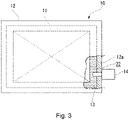
- Fig. 3 is a partially sectional side view showing a speed reducer 10 according to a second embodiment.
- the speed reducer 10 includes: a speed reducing mechanism unit 11 for decelerating input rotation to a predetermined reduction ratio; and a casing 12 that houses the speed reducing mechanism unit 11.
- the inner space within the casing 12 is filled with a lubricant 13 for lubricating the speed reducing mechanism unit 11 and other mechanical contact parts.
- a conductive particle detecting device 14 is mounted to a wall 12a of the casing 12. The conductive particle detecting device 14 detects conductive particles such as metal powder mixing into the lubricant 13.
- Fig. 4 is a perspective view showing a part of the conductive particle detecting device 14 longitudinally sectioned along the longitudinal direction.
- Fig. 5 is an enlarged view of the portion V of Fig. 4 .
- Fig. 6 is a sectional view along a line VI-VI in Fig. 4 .
- the conductive particle detecting device 14 includes a device body 16 having a substantially tubular shape, a support block 17 fixed to the inside of the device body 16, and a flexible printed wiring board 102 (wiring) supported by the support block 17.
- the conductive particle detecting device 14 includes: four permanent magnets 3 connected via the relay pieces 4 to one end portion of the flexible printed wiring board 102 in the longitudinal direction; and a detecting circuit board 18 connected to the other end portion of the flexible printed wiring board 102 in the longitudinal direction.
- the permanent magnets 3, the flexible printed wiring board 102, and the relay pieces 4 constitute a wiring structure 101 according to the embodiment.
- the device body 16 is mounted to the casing 12 (see Fig. 3 ) of the speed reducer 10.
- the wall 12a of the casing 12 has a screw hole penetrating the wall 12a.
- the device body 16 is formed of, for example, a metal.
- the device body 16 includes a fixed tube 16a having a cylindrical shape and a flange portion 16b.
- the fixed tube 16a is fastened into the screw hole formed in the wall 12a.
- the flange portion 16b is integrated with the other end portion of the fixed tube 16a (the end portion positioned outside the casing 12).
- a male thread 19 is formed in the outer circumferential surface of the fixed tube 16a.
- the male thread 19 is fastened into the screw hole in the wall 12a.
- a device cover 20 having a bottomed tubular shape is provided outside the flange portion 16b.
- the device cover 20 is fixed with bolts 21 (fastening members) to an outside end surface of the flange portion 16b (the end surface facing toward the opposite side to the casing 12).
- a grommet 5 (sealing member) shaped like a disc seals between the device cover 20 and the flange portion 16b.
- the grommet 5 is integrated with a part of an insulating layer 102a (see Fig. 7 ) of the flexible printed wiring board 102.
- the flexible printed wiring board 102 is integrated with the grommet 5 so as to penetrate the grommet 5 in the thickness direction thereof.
- the detecting circuit board 18 is mounted to the outside end surface of the grommet 5 (the end surface facing toward the opposite side to the casing 12).
- the detecting circuit board 18 is covered by the device cover 20.
- the grommet 5 is fixed to the device cover 20 and the flange portion 16b, with the peripheral edge of the grommet 5 nipped between the device cover 20 and the flange portion 16b.
- the grommet 5 seals between the lubricant-filled space 22 (see Fig. 3 ) inside the casing 12 and a detection space 23 (the space inside the device cover 20) in which the detecting circuit board 18 is disposed.
- the support block 17 is formed of a resin material and shaped like a hollow quadrangular prism.
- the other end portion (hereinafter referred to as “the proximal portion”) of the support block 17 in the longitudinal direction is fixed to the inside of the device body 16.
- the support block 17 is positioned along the axial direction of the fixed tube 16a.
- One end portion (hereinafter referred to as “the distal end portion”) of the support block 17 in the longitudinal direction projects out of the fixed tube 16a of the device body 16 (to the inside of the casing 12).
- the outer peripheral surface and the distal end surface of the distal end portion of the support block 17 are covered by a detecting unit cover 24 having a bottomed tubular shape.
- the detecting unit cover 24 is integrally formed of a resin material.
- the detecting unit cover 24 includes a peripheral wall 24a and an end wall 24b.
- the peripheral wall 24a has four detection windows 25, and the end wall 24b closes the axial end portion of the peripheral wall 24a.
- the four detection windows 25 of the peripheral wall 24a are arranged at regular intervals and spaced apart from each other by about 90° in the outer periphery of the peripheral wall 24a.
- Each of the detection windows 25 has a substantially rectangular shape in front view. Of the edges constituting each detection window 25, those on both sides along the circumferential direction of the peripheral wall 24a are formed in tapered surfaces 25a.
- the tapered surfaces 25a are formed such that the opening area of the detection window 25 increases gradually radially outward.
- the end wall 24b of the detecting unit cover 24 is riveted to the distal end surface of the support block 17.
- the sign 26 in the drawing denotes a rivet for fixing the detecting unit cover 24 to the support block 17.
- Fig. 7 is a plan view showing the flexible printed wiring board 102.
- the flexible printed wiring board 102 according to the embodiment includes a base portion 102b and four branch portions 102c branched from the base portion 102b.
- the base portion 102b penetrates the grommet 5 in the thickness direction thereof.
- the flexible printed wiring board 102 includes conductive portions 50 extending from the base portion 102b to the distal end portions of the branch portions 102c.
- the other end portion (the terminal portion) of the conductive portions 50 is positioned outside the casing 12 and connected to the detecting circuit board 18.
- Each of the four branch portions 102c branched from the base portion 102b is positioned along associated one of the four surfaces on the outer periphery of the support block 17.
- Support grooves 27 are formed in the four surfaces on the outer periphery of the support block 17 so as to extend along the longitudinal direction of the support block 17. In each surface of the support block 17, the branch portion 102c is supported in the support groove 27.
- each of the branch portions 102c one end portion of the conductive portion 50 is connected with the relay piece 4.
- the relay piece 4 is formed of a metal magnetic material and has a substantially rectangular shape.
- the relay piece 4 is connected to the conductive portion 50 with a conductive adhesive or by soldering.
- each relay piece 4 is supported in the associated support groove 27 along with the branch portion 102c.
- each relay piece 4 facing the opposite side to the support block 17 (hereinafter referred to as "the surface") is formed flat.
- the surface of each relay piece 4 has the associated permanent magnet 3 fixed thereto by magnetic attraction.
- the permanent magnet 3 is fixed to the relay piece 4 by combined use of a conductive adhesive.
- the detecting unit cover 24 is mounted to the distal end portion of the support block 17.
- the detecting unit cover 24 is positioned such that each of the four permanent magnets 3 is positioned on the inner side of the associated one of the four detection windows 25 (on the inner side in the radial direction of the peripheral wall 24a).
- the detecting unit cover 24 is riveted to the distal end surface of the support block 17.
- the end surface of the peripheral wall 24a of the detecting unit cover 24 (the end surface on the opposite side to the end wall 24b) abuts against the end surface of the fixed tube 16a of the device body 16.
- the distal end portion of the conductive particle detecting device 14 is inserted into the casing 12 through the screw hole in the wall 12a.
- the fixed tube 16a of the conductive particle detecting device 14 is fastened into the screw hole.
- the conductive particle detecting device 14 is fixed to the casing 12.
- the lubricant 13 is then filled into the casing 12, and the plurality of permanent magnets 3 and the detecting unit cover 24 are immersed in the lubricant 13.
- the detecting circuit board 18 includes a resistance detecting circuit.
- the resistance detecting circuit detects the electrical resistance between the plurality of permanent magnets 3 arranged adjacent to each other on the outer periphery of the support block 17. As shown in Fig. 6 , the plurality of permanent magnets 3 are spaced apart from each other. Therefore, in the initial state in which the permanent magnets 3 are immersed in the lubricant 13, the resistance value between adjacent permanent magnets 3 is infinite. After that, when a large amount of conductive particles (such as metal powder) mixes into the lubricant 13 as the speed reducer 10 is used, the conductive particles in the lubricant 13 are attracted by the plurality of permanent magnets 3 of the conductive particle detecting device 14.
- conductive particles such as metal powder
- the conductive particles attracted are moved through the detection windows 25 of the detecting unit cover 24 and adhered onto the surfaces of the permanent magnets 3. Also, the conductive particles attracted are adhered onto the outer peripheral surface of the detecting unit cover 24 by the magnetic force of the permanent magnets 3.
- a larger amount of conductive particles are also adhered onto the outer peripheral surface of the detecting unit cover 24.
- the detecting circuit board 18 detects that the resistance value has fallen below the preset value.
- the detecting circuit board 18 is connected to a display device or an alarm device via a controller. Through the display device or the alarm device, an operator and the like can determine that the amount of conductive particles in the speed reducer 10 has exceeded the preset amount.
- the conductive particle detecting device 14 of the embodiment includes: the plurality of permanent magnets 3 having electrical conductivity and spaced apart from each other; the detecting circuit board 18; the flexible printed wiring board 102 connecting between the detecting circuit board 18 and the permanent magnets 3; and the relay pieces 4 made of a metal magnetic material, the relay pieces 4 being connected to conductive portions 50 of the flexible printed wiring board 102 on the permanent magnet 3 side and having the permanent magnets 3 attached thereto by magnetic attraction.
- the permanent magnets 3 having electrical conductivity can be fixed to the relay pieces 4 by magnetic attraction.
- the relay pieces 4 made of a metal magnetic material can be firmly fixed to the conductive portions 50 of the flexible printed wiring board 102.
- the conductive portions 50 of the flexible printed wiring board 102 and the relay pieces 4 can be connected by the conductive adhesive, thereby stabilizing the fixation of the relay pieces 4 to the conductive portions 50 of the flexible printed wiring board 102 in a conductive manner.
- the conductive particle detecting device 14 of the embodiment uses the flexible printed wiring board 102 as wiring for electrically connecting the permanent magnets 3 and the detecting circuit board 18. Therefore, the wiring can run freely even in a small installation space within the conductive particle detecting device 14, and the wiring form can be stable.
- the grommet 5 (sealing member) is integrated with the flexible printed wiring board 102.
- the grommet seals between the lubricant-filled space 22 in the speed reducer 10 filled with the lubricant 13 and the detection space 23 in which the detecting circuit board 18 is disposed. This simple structure facilitates manufacturing and assembling and also securely prevents the lubricant 13 from entering the detection space 23.
Landscapes
- Chemical & Material Sciences (AREA)
- Health & Medical Sciences (AREA)
- Life Sciences & Earth Sciences (AREA)
- Engineering & Computer Science (AREA)
- General Physics & Mathematics (AREA)
- Immunology (AREA)
- Pathology (AREA)
- General Health & Medical Sciences (AREA)
- Biochemistry (AREA)
- Analytical Chemistry (AREA)
- Physics & Mathematics (AREA)
- Chemical Kinetics & Catalysis (AREA)
- Electrochemistry (AREA)
- Microelectronics & Electronic Packaging (AREA)
- Medicinal Chemistry (AREA)
- Food Science & Technology (AREA)
- Oil, Petroleum & Natural Gas (AREA)
- General Chemical & Material Sciences (AREA)
- General Engineering & Computer Science (AREA)
- Quality & Reliability (AREA)
- Dispersion Chemistry (AREA)
- Mechanical Engineering (AREA)
- Investigating Or Analyzing Materials By The Use Of Electric Means (AREA)
- General Details Of Gearings (AREA)
- Measurement Of Radiation (AREA)
- Parts Printed On Printed Circuit Boards (AREA)
- Manufacturing Of Printed Wiring (AREA)
- Investigating Or Analyzing Materials By The Use Of Magnetic Means (AREA)
Abstract
Description
- The present invention relates to a wiring structure, a conductive particle detecting device using the wiring structure, and a speed reducer using the conductive particle detecting device.
- In apparatuses containing a mechanical mechanism (such as a speed reducer), a casing is filled with a lubricant to reduce the wear in the mechanism. In operation of such apparatuses, metal powder is produced from mechanical parts. The metal powder produced from the mechanical parts mixes into the lubricant within the casing. When a large amount of metal powder mixes into the lubricant, the ability of the lubricant to inhibit the wear in the mechanism is reduced. The presence of the large amount of metal powder mixed into the lubricant indicates that the wear or damage has occurred in the mechanism.
- For the above apparatuses, a device should preferably externally detect that the amount of the metal powder in the lubricant has exceeded a preset value. Devices for externally detecting the amount of the metal powder are disclosed (see, for example, Patent Literature 1). With these devices, the metal powder in the lubricant is attracted by a permanent magnet, thereby electrically detecting the amount of the attracted metal powder.
- The detecting device (the conductive particle detecting device) disclosed in
Patent Literature 1 includes a tubular permanent magnet disposed in the lubricant and a plurality of electrodes disposed outside the permanent magnet and spaced apart from each other by a gap. The conductive particle detecting device is configured to detect the resistance between adjacent electrodes spaced apart from each other by the gap, thereby determining the amount of metal powder mixing into the lubricant. - Patent Literature 1:
Japanese Patent Application Publication No. 2005-331324 - Some conductive particle detecting devices proposed in recent years include a plurality of permanent magnets having electrical conductivity used as electrodes. In the conductive particle detecting devices, the permanent magnets serve as both attracting portions for conductive particles (such as metal powder) and electrode portions. Each of the permanent magnets is connected through wiring to a resistance detecting circuit on a detecting circuit board.
- A wiring structure connecting between the detecting circuit board and the conductive permanent magnets includes a connecting means for connecting between a conductive portion of the wiring and a corresponding permanent magnet. The connecting means is formed of a screw or a conductive clamping lock.
- When the connecting means is formed of a screw, the permanent magnet needs to have a screw hole formed therein. However, it is generally difficult to form a screw hole in a permanent magnet to a high accuracy. The clamping lock as the connecting means is a large-sized part. Therefore, use of the clamping lock as the connecting means causes increase of the size of the entire wiring structure.
- The present invention provides a wiring structure, a conductive particle detecting device, and a speed reducer, in which it is possible to easily connect between a conductive portion of the wiring and a conductive permanent magnet without an increase of the size of a connecting portion.
- A wiring structure according to one aspect of the present invention comprises: a permanent magnet having electrical conductivity; a wiring having a conductive portion; and a relay piece made of a metal magnetic material, the relay piece being connected to the conductive portion, the permanent magnet being fixed to the relay piece by magnetic attraction.
- The wiring is preferably formed of a flexible printed wiring board.
- The relay piece and the permanent magnet may be connected by a conductive adhesive.
- A conductive particle detecting device according to one aspect of the present invention comprises: a plurality of permanent magnets having electrical conductivity and spaced apart from each other; a detecting circuit board for detecting conductive particles attracted between adjacent ones of the plurality of permanent magnets, based on electrical resistance between the adjacent ones of the plurality of permanent magnets; a flexible printed wiring board electrically connecting the detecting circuit board and the plurality of permanent magnets; and a plurality of relay pieces connected to conductive portions of the flexible printed wiring board. The plurality of relay pieces are made of a metal magnetic material. The plurality of permanent magnets are fixed to the plurality of relay pieces, respectively, by magnetic attraction.
- The conductive portions and the plurality of relay pieces may be connected by solder.
- The conductive portions and the plurality of relay pieces may be connected by a conductive adhesive.
- The conductive particle detecting device may further comprise: a sealing member sealing between a lubricant-filled space containing the plurality of permanent magnets and filled with a lubricant and a detection space containing the detecting circuit board. The sealing member may be integrated with the flexible printed wiring board.
- A speed reducer according to one aspect of the present invention comprises: a speed reducing mechanism unit for reducing a speed of rotation input thereto; a casing containing the speed reducing mechanism unit; and a conductive particle detecting device for detecting conductive particles mixing into a lubricant in the casing. The conductive particle detecting device includes: a plurality of permanent magnets having electrical conductivity and spaced apart from each other within the casing; a detecting circuit board for detecting conductive particles attracted between adjacent ones of the plurality of permanent magnets, based on electrical resistance between the adjacent ones of the plurality of permanent magnets; a flexible printed wiring board electrically connecting the detecting circuit board and the plurality of permanent magnets; and a plurality of relay pieces connected to conductive portions of the flexible printed wiring board. The plurality of relay pieces are made of a metal magnetic material. The plurality of permanent magnets are fixed to the plurality of relay pieces, respectively, by magnetic attraction.
- The above wiring structure includes the relay piece made of a metal magnetic material and connected to the conductive portion of the wiring, and the permanent magnet is fixed to the relay piece by magnetic attraction. Therefore, in connecting the conductive portion of the wiring and the permanent magnet having electrical conductivity, there is no need of a cutting process for forming a screw hole or the like in the permanent magnet. Accordingly, with the above wiring structure, it is possible to easily connect the conductive portion of the wiring and the permanent magnet having electrical conductivity without increase of the size of the connection portion.
-
-
Fig. 1 is a perspective view showing a wiring structure according to a first embodiment. -
Fig. 2 is a perspective view showing a part of a manufacturing process of the wiring structure according to the first embodiment. -
Fig. 3 is a partially sectional side view showing a speed reducer having mounted thereto a conductive particle detecting device according to a second embodiment. -
Fig. 4 is a partial sectional perspective view showing the conductive particle detecting device according to the second embodiment. -
Fig. 5 is a partial sectional perspective view showing, in an enlarged scale, the V portion inFig. 4 of the conductive particle detecting device according to the second embodiment. -
Fig. 6 is a sectional view showing the conductive particle detecting device according to the second embodiment cut along the line VI-VI inFig. 4 . -
Fig. 7 is a plan view showing a flexible printed wiring board used in the conductive particle detecting device according to the second embodiment. - The embodiments of the present invention will be hereinafter described with reference to the drawings. In the following embodiments, like elements will be denoted by the same reference signs and redundant descriptions will be partly omitted.
-
Fig. 1 is a perspective view showing awiring structure 1 according to a first embodiment. Thewiring structure 1 of the embodiment includes apermanent magnet 3 having electrical conductivity, a flexible printed wiring board (a form of wiring) 2, and arelay piece 4 formed of a metal magnetic material. - The
permanent magnet 3 is shaped like a rectangular plate with some degree of thickness. The flexible printedwiring board 2 is shaped like a belt. The flexible printedwiring board 2 includes a conductive portion (not shown) extending from one end of the flexible printedwiring board 2 toward the other end in the longitudinal direction. The conductive portion is covered by aninsulating layer 2a having flexibility. One end portion and the other end portion of the conductive portion form a terminal portion (not shown) exposed to the outside of theinsulating layer 2a. - The
relay piece 4 is soldered to one end portion of the terminal portion. Thus, therelay piece 4 is electrically connected to the conductive portion of the flexible printedwiring board 2. Therelay piece 4 is formed of a magnetic material such as a metal. Thepermanent magnet 3 can be attached to therelay piece 4 by magnetic attraction. Therelay piece 4 is shaped like a rectangular plate having substantially the same width as the flexible printedwiring board 2. The top and bottom surfaces (the surfaces facing toward the thickness direction) of therelay piece 4 are flat. In the embodiment, therelay piece 4 is soldered to the terminal portion (the conductive portion) of the flexible printedwiring board 2. It is also possible to use a conductive adhesive to connect therelay piece 4 to the terminal portion (the conductive portion) of the flexible printedwiring board 2. In this case, the conductive adhesive electrically connects between therelay piece 4 and the terminal portion of the flexible printedwiring board 2. Since therelay piece 4 is shaped like a rectangular plate having substantially the same width as the flexible printedwiring board 2, therelay piece 4 and the flexible printedwiring board 2 can be fixed with an adhesive to each other at the surfaces thereof facing the thickness direction, such that therelay piece 4 is stably fixed to the flexible printedwiring board 2. -
Fig. 2 shows a step of connecting thepermanent magnet 3 to therelay piece 4 after therelay piece 4 is connected to the terminal portion (the conductive portion) of the flexible printedwiring board 2. Thepermanent magnet 3 is fixed by magnetic attraction to therelay piece 4 connected to the flexible printedwiring board 2. In the embodiment, a conductive adhesive is provided between thepermanent magnet 3 and therelay piece 4. Thus, thepermanent magnet 3 and therelay piece 4 are fixed together by the magnetic force of thepermanent magnet 3 and the adhesive strength of the adhesive. - The other end portion of the terminal portion can be connected to a circuit board having a resistance detecting circuit or the like (not shown). In the embodiment, the longitudinally midway portion of the flexible printed
wiring board 2 has integrally formed thereon agrommet 5 that serves as a sealing member. In installing thewiring structure 1 on a mechanical device such as a speed reducer, thegrommet 5 is fitted into a through-hole formed in a casing of the mechanical device. In the through-hole, thegrommet 5 seals between the casing and the flexible printedwiring board 2. The flexible printedwiring board 2 extends through the through-hole and is present both inside and outside the mechanical device. In other words, thegrommet 5 seals between a lubricant-filled space (inside of the mechanical device) in which thepermanent magnet 3 is disposed and a circuit board-containing space (detection space, outside of the mechanical device) in which the circuit board is disposed. - The
wiring structure 1 of the embodiment includes thepermanent magnet 3 having electrical conductivity, a flexible printed wiring board 2 (wiring) including the conductive portion, and therelay piece 4 formed of a metal magnetic material, therelay piece 4 being connected to the conductive portion of the flexible printedwiring board 2 and having thepermanent magnet 3 fixed thereto by magnetic attraction. Therefore, thepermanent magnet 3 can be fixed to therelay piece 4 by magnetic attraction for connection between the conductive portion of the flexible printed wiring board 2 (wiring) and thepermanent magnet 3. There is no need of a cutting process for forming a screw hole or the like in thepermanent magnet 3. Accordingly, with thewiring structure 1 of the embodiment, it is possible to easily connect between the conductive portion of the flexible printed wiring board 2 (wiring) and thepermanent magnet 3 without increase of the size of the connection portion. - The wiring for electrically connecting between the
permanent magnet 3 and the circuit board may be formed of a coated conductive wire having a circular or rectangular cross section, in place of the flexible printedwiring board 2. However, when the flexible printedwiring board 2 is used as the wiring for electrically connecting between thepermanent magnet 3 and the circuit board, as in thewiring structure 1 of the embodiment, the wiring can run freely even in a small installation space, and the wiring form can be stable. Since the flexible printedwiring board 2 has a flat surface, therelay piece 4 can be stably supported on the flat surface of the flexible printedwiring board 2. - In the
wiring structure 1 of the embodiment, therelay piece 4 and thepermanent magnet 3 are connected together also with the conductive adhesive. Therefore, thepermanent magnet 3 can be fixed firmly to therelay piece 4 by the adhesive strength of the conductive adhesive, in addition to the attractive force of thepermanent magnet 3. In actually connecting thepermanent magnet 3 to therelay piece 4, it is necessary only to previously apply the conductive adhesive to at least one of therelay piece 4 or thepermanent magnet 3 and allow thepermanent magnet 3 to be attached to therelay piece 4 by magnetic attraction. Thus, there is no complexity in manufacturing thewiring structure 1. - In the
wiring structure 1 of the embodiment, therelay piece 4 has a flat surface. Thepermanent magnet 3 is fixed to the flat surface of therelay piece 4 by magnetic attraction. Therefore, this configuration stabilizes the electrical connection and mechanical fixation between therelay piece 4 and thepermanent magnet 3. - Even when the
relay piece 4 and the conductive portion of the flexible printed wiring board 2 (wiring) are formed of such a material or have such structure as to be less suited for connection by solder, therelay piece 4 can be connected to the conductive portion of the flexible printed wiring board 2 (wiring) with the conductive adhesive, thereby stabilizing the connection between therelay piece 4 and the conductive portion of the flexible printed wiring board 2 (wiring) in a conductive manner. -
Fig. 3 is a partially sectional side view showing aspeed reducer 10 according to a second embodiment. Thespeed reducer 10 includes: a speed reducingmechanism unit 11 for decelerating input rotation to a predetermined reduction ratio; and acasing 12 that houses the speed reducingmechanism unit 11. The inner space within thecasing 12 is filled with alubricant 13 for lubricating the speed reducingmechanism unit 11 and other mechanical contact parts. A conductiveparticle detecting device 14 is mounted to awall 12a of thecasing 12. The conductiveparticle detecting device 14 detects conductive particles such as metal powder mixing into thelubricant 13. -
Fig. 4 is a perspective view showing a part of the conductiveparticle detecting device 14 longitudinally sectioned along the longitudinal direction.Fig. 5 is an enlarged view of the portion V ofFig. 4 .Fig. 6 is a sectional view along a line VI-VI inFig. 4 . The conductiveparticle detecting device 14 includes adevice body 16 having a substantially tubular shape, asupport block 17 fixed to the inside of thedevice body 16, and a flexible printed wiring board 102 (wiring) supported by thesupport block 17. The conductiveparticle detecting device 14 includes: fourpermanent magnets 3 connected via therelay pieces 4 to one end portion of the flexible printedwiring board 102 in the longitudinal direction; and a detectingcircuit board 18 connected to the other end portion of the flexible printedwiring board 102 in the longitudinal direction. Thepermanent magnets 3, the flexible printedwiring board 102, and therelay pieces 4 constitute awiring structure 101 according to the embodiment. - The
device body 16 is mounted to the casing 12 (seeFig. 3 ) of thespeed reducer 10. Thewall 12a of thecasing 12 has a screw hole penetrating thewall 12a. Thedevice body 16 is formed of, for example, a metal. Thedevice body 16 includes a fixedtube 16a having a cylindrical shape and aflange portion 16b. The fixedtube 16a is fastened into the screw hole formed in thewall 12a. Thus, thedevice body 16 is mounted to thecasing 12 in such a manner as to penetrate thewall 12a. Theflange portion 16b is integrated with the other end portion of the fixedtube 16a (the end portion positioned outside the casing 12). - A
male thread 19 is formed in the outer circumferential surface of the fixedtube 16a. Themale thread 19 is fastened into the screw hole in thewall 12a. Adevice cover 20 having a bottomed tubular shape is provided outside theflange portion 16b. Thedevice cover 20 is fixed with bolts 21 (fastening members) to an outside end surface of theflange portion 16b (the end surface facing toward the opposite side to the casing 12). A grommet 5 (sealing member) shaped like a disc seals between thedevice cover 20 and theflange portion 16b. Thegrommet 5 is integrated with a part of an insulatinglayer 102a (seeFig. 7 ) of the flexible printedwiring board 102. The flexible printedwiring board 102 is integrated with thegrommet 5 so as to penetrate thegrommet 5 in the thickness direction thereof. - The detecting
circuit board 18 is mounted to the outside end surface of the grommet 5 (the end surface facing toward the opposite side to the casing 12). The detectingcircuit board 18 is covered by thedevice cover 20. Thegrommet 5 is fixed to thedevice cover 20 and theflange portion 16b, with the peripheral edge of thegrommet 5 nipped between thedevice cover 20 and theflange portion 16b. Thegrommet 5 seals between the lubricant-filled space 22 (seeFig. 3 ) inside thecasing 12 and a detection space 23 (the space inside the device cover 20) in which the detectingcircuit board 18 is disposed. - The
support block 17 is formed of a resin material and shaped like a hollow quadrangular prism. The other end portion (hereinafter referred to as "the proximal portion") of thesupport block 17 in the longitudinal direction is fixed to the inside of thedevice body 16. Thesupport block 17 is positioned along the axial direction of the fixedtube 16a. One end portion (hereinafter referred to as "the distal end portion") of thesupport block 17 in the longitudinal direction projects out of the fixedtube 16a of the device body 16 (to the inside of the casing 12). - The outer peripheral surface and the distal end surface of the distal end portion of the
support block 17 are covered by a detectingunit cover 24 having a bottomed tubular shape. The detectingunit cover 24 is integrally formed of a resin material. The detectingunit cover 24 includes aperipheral wall 24a and anend wall 24b. Theperipheral wall 24a has fourdetection windows 25, and theend wall 24b closes the axial end portion of theperipheral wall 24a. The fourdetection windows 25 of theperipheral wall 24a are arranged at regular intervals and spaced apart from each other by about 90° in the outer periphery of theperipheral wall 24a. Each of thedetection windows 25 has a substantially rectangular shape in front view. Of the edges constituting eachdetection window 25, those on both sides along the circumferential direction of theperipheral wall 24a are formed intapered surfaces 25a. The tapered surfaces 25a are formed such that the opening area of thedetection window 25 increases gradually radially outward. - The
end wall 24b of the detectingunit cover 24 is riveted to the distal end surface of thesupport block 17. Thesign 26 in the drawing denotes a rivet for fixing the detectingunit cover 24 to thesupport block 17. -
Fig. 7 is a plan view showing the flexible printedwiring board 102. As shown inFig. 7 , the flexible printedwiring board 102 according to the embodiment includes abase portion 102b and fourbranch portions 102c branched from thebase portion 102b. Thebase portion 102b penetrates thegrommet 5 in the thickness direction thereof. The flexible printedwiring board 102 includesconductive portions 50 extending from thebase portion 102b to the distal end portions of thebranch portions 102c. The other end portion (the terminal portion) of theconductive portions 50 is positioned outside thecasing 12 and connected to the detectingcircuit board 18. Each of the fourbranch portions 102c branched from thebase portion 102b is positioned along associated one of the four surfaces on the outer periphery of thesupport block 17. Support grooves 27 (seeFig. 6 ) are formed in the four surfaces on the outer periphery of thesupport block 17 so as to extend along the longitudinal direction of thesupport block 17. In each surface of thesupport block 17, thebranch portion 102c is supported in thesupport groove 27. - At the distal end portion of each of the
branch portions 102c, one end portion of theconductive portion 50 is connected with therelay piece 4. Therelay piece 4 is formed of a metal magnetic material and has a substantially rectangular shape. Therelay piece 4 is connected to theconductive portion 50 with a conductive adhesive or by soldering. On the distal end side of thesupport block 17, eachrelay piece 4 is supported in the associatedsupport groove 27 along with thebranch portion 102c. - The surface of each
relay piece 4 facing the opposite side to the support block 17 (hereinafter referred to as "the surface") is formed flat. The surface of eachrelay piece 4 has the associatedpermanent magnet 3 fixed thereto by magnetic attraction. In the embodiment, it is also possible that thepermanent magnet 3 is fixed to therelay piece 4 by combined use of a conductive adhesive. - After the
relay piece 4 and thepermanent magnet 3 are mounted to each surface on the outer periphery of thesupport block 17, the detectingunit cover 24 is mounted to the distal end portion of thesupport block 17. The detectingunit cover 24 is positioned such that each of the fourpermanent magnets 3 is positioned on the inner side of the associated one of the four detection windows 25 (on the inner side in the radial direction of theperipheral wall 24a). In this state, the detectingunit cover 24 is riveted to the distal end surface of thesupport block 17. At this time, the end surface of theperipheral wall 24a of the detecting unit cover 24 (the end surface on the opposite side to theend wall 24b) abuts against the end surface of the fixedtube 16a of thedevice body 16. - The distal end portion of the conductive
particle detecting device 14 is inserted into thecasing 12 through the screw hole in thewall 12a. In this state, the fixedtube 16a of the conductiveparticle detecting device 14 is fastened into the screw hole. Thus, the conductiveparticle detecting device 14 is fixed to thecasing 12. Thelubricant 13 is then filled into thecasing 12, and the plurality ofpermanent magnets 3 and the detectingunit cover 24 are immersed in thelubricant 13. - The detecting
circuit board 18 includes a resistance detecting circuit. The resistance detecting circuit detects the electrical resistance between the plurality ofpermanent magnets 3 arranged adjacent to each other on the outer periphery of thesupport block 17. As shown inFig. 6 , the plurality ofpermanent magnets 3 are spaced apart from each other. Therefore, in the initial state in which thepermanent magnets 3 are immersed in thelubricant 13, the resistance value between adjacentpermanent magnets 3 is infinite. After that, when a large amount of conductive particles (such as metal powder) mixes into thelubricant 13 as thespeed reducer 10 is used, the conductive particles in thelubricant 13 are attracted by the plurality ofpermanent magnets 3 of the conductiveparticle detecting device 14. The conductive particles attracted are moved through thedetection windows 25 of the detectingunit cover 24 and adhered onto the surfaces of thepermanent magnets 3. Also, the conductive particles attracted are adhered onto the outer peripheral surface of the detectingunit cover 24 by the magnetic force of thepermanent magnets 3. - As a larger amount of conductive particles mix into the
lubricant 13, a larger amount of conductive particles are also adhered onto the outer peripheral surface of the detectingunit cover 24. When the amount of conductive particles adhered exceeds a certain amount, the resistance value between adjacent ones of thepermanent magnets 3 falls below a preset value. The detectingcircuit board 18 detects that the resistance value has fallen below the preset value. The detectingcircuit board 18 is connected to a display device or an alarm device via a controller. Through the display device or the alarm device, an operator and the like can determine that the amount of conductive particles in thespeed reducer 10 has exceeded the preset amount. - As described above, the conductive
particle detecting device 14 of the embodiment includes: the plurality ofpermanent magnets 3 having electrical conductivity and spaced apart from each other; the detectingcircuit board 18; the flexible printedwiring board 102 connecting between the detectingcircuit board 18 and thepermanent magnets 3; and therelay pieces 4 made of a metal magnetic material, therelay pieces 4 being connected toconductive portions 50 of the flexible printedwiring board 102 on thepermanent magnet 3 side and having thepermanent magnets 3 attached thereto by magnetic attraction. In the conductiveparticle detecting device 14 of the embodiment, thepermanent magnets 3 having electrical conductivity can be fixed to therelay pieces 4 by magnetic attraction. Therefore, in connecting theconductive portions 50 of the flexible printedwiring board 102 and thepermanent magnets 3 having electrical conductivity, there is no need of a cutting process for forming a screw hole or the like in thepermanent magnets 3. Accordingly, with the conductiveparticle detecting device 14 of the embodiment, it is possible to easily connect theconductive portions 50 of the flexible printedwiring board 102 and thepermanent magnets 3 having electrical conductivity without increase of the size of the connection portion. - In the conductive
particle detecting device 14 of the embodiment, when theconductive portions 50 of the flexible printedwiring board 102 and therelay pieces 4 are connected by solder, therelay pieces 4 made of a metal magnetic material can be firmly fixed to theconductive portions 50 of the flexible printedwiring board 102. - In the conductive
particle detecting device 14 of the embodiment, even when therelay pieces 4 and theconductive portions 50 of the flexible printedwiring board 102 are formed of such a material or have such structure as to be less suited for connection by solder, theconductive portions 50 of the flexible printedwiring board 102 and therelay pieces 4 can be connected by the conductive adhesive, thereby stabilizing the fixation of therelay pieces 4 to theconductive portions 50 of the flexible printedwiring board 102 in a conductive manner. - The conductive
particle detecting device 14 of the embodiment uses the flexible printedwiring board 102 as wiring for electrically connecting thepermanent magnets 3 and the detectingcircuit board 18. Therefore, the wiring can run freely even in a small installation space within the conductiveparticle detecting device 14, and the wiring form can be stable. - In the conductive
particle detecting device 14 of the embodiment, the grommet 5 (sealing member) is integrated with the flexible printedwiring board 102. The grommet seals between the lubricant-filledspace 22 in thespeed reducer 10 filled with thelubricant 13 and thedetection space 23 in which the detectingcircuit board 18 is disposed. This simple structure facilitates manufacturing and assembling and also securely prevents thelubricant 13 from entering thedetection space 23. - The present invention is not limited to the above-described embodiments and can be modified in a variety of designs without deviating from the spirit of the present disclosure.
-
- 1, 101
- wiring structure
- 2, 102
- flexible printed wiring board (wiring)
- 3
- permanent magnet
- 4
- relay piece
- 5
- grommet
- 10
- speed reducer
- 11
- speed reducing mechanism unit
- 12
- casing
- 13
- lubricant
- 14
- conductive particle detecting device
- 18
- detecting circuit board
- 22
- lubricant-filled space
- 23
- detection space
- 50
- conductive portion
Claims (8)
- A wiring structure (1) comprising:a permanent magnet (3) having electrical conductivity;a wiring (2) having a conductive portion; anda relay piece (4) made of a metal magnetic material, the relay piece (4) being connected to the conductive portion, the permanent magnet (3) being fixed to the relay piece (4) by magnetic attraction.
- The wiring structure (1) of claim 1, wherein the wiring (2) is formed of a flexible printed wiring board (2).
- The wiring structure (1) of claim 1 or 2, wherein the relay piece (4) and the permanent magnet (3) are connected by a conductive adhesive.
- A conductive particle detecting device (14), comprising:a plurality of permanent magnets (3) having electrical conductivity and spaced apart from each other;a detecting circuit board (18) for detecting conductive particles attracted between adjacent ones of the plurality of permanent magnets (3), based on electrical resistance between the adjacent ones of the plurality of permanent magnets (3);a flexible printed wiring board (2) electrically connecting the detecting circuit board (18) and the plurality of permanent magnets (3); anda plurality of relay pieces (4) connected to conductive portions (50) of the flexible printed wiring board (2),wherein the plurality of relay pieces (4) are made of a metal magnetic material, andwherein the plurality of permanent magnets (3) are fixed to the plurality of relay pieces (4), respectively, by magnetic attraction.
- The conductive particle detecting device (14) of claim 4, wherein the conductive portions (50) and the plurality of relay pieces (4) are connected by solder.
- The conductive particle detecting device (14) of claim 4, wherein the conductive portions (50) and the plurality of relay pieces (4) are connected by a conductive adhesive.
- The conductive particle detecting device (14) of any one of claims 4 to 6, further comprising:a sealing member (5) sealing between a lubricant-filled space (22) containing the plurality of permanent magnets (3) and filled with a lubricant and a detection space (23) containing the detecting circuit board (18),wherein the sealing member (5) is integrated with the flexible printed wiring board (2).
- A speed reducer (10) comprising:a speed reducing mechanism unit (11) for reducing a speed of rotation input thereto;a casing (12) containing the speed reducing mechanism unit (11); anda conductive particle detecting device (14) for detecting conductive particles mixing into a lubricant in the casing (12),wherein the conductive particle detecting device (14) includes:a plurality of permanent magnets (3) having electrical conductivity and spaced apart from each other within the casing (12);a detecting circuit board (18) for detecting conductive particles attracted between adjacent ones of the plurality of permanent magnets (3), based on electrical resistance between the adjacent ones of the plurality of permanent magnets (3);a flexible printed wiring board (2) electrically connecting the detecting circuit board (18) and the plurality of permanent magnets (3); anda plurality of relay pieces (4) connected to conductive portions (50) of the flexible printed wiring board (2),wherein the plurality of relay pieces (4) are made of a metal magnetic material, andwherein the plurality of permanent magnets (3) are fixed to the plurality of relay pieces (4), respectively, by magnetic attraction.
Applications Claiming Priority (1)
| Application Number | Priority Date | Filing Date | Title |
|---|---|---|---|
| JP2021040414A JP7604276B2 (en) | 2021-03-12 | 2021-03-12 | Conductive particle detection device and reducer |
Publications (2)
| Publication Number | Publication Date |
|---|---|
| EP4056986A1 true EP4056986A1 (en) | 2022-09-14 |
| EP4056986B1 EP4056986B1 (en) | 2024-07-17 |
Family
ID=80682504
Family Applications (1)
| Application Number | Title | Priority Date | Filing Date |
|---|---|---|---|
| EP22160550.4A Active EP4056986B1 (en) | 2021-03-12 | 2022-03-07 | Conductive particle detecting device, and speed reducer |
Country Status (6)
| Country | Link |
|---|---|
| US (1) | US11774387B2 (en) |
| EP (1) | EP4056986B1 (en) |
| JP (1) | JP7604276B2 (en) |
| KR (1) | KR20220128280A (en) |
| CN (1) | CN115078465A (en) |
| TW (1) | TW202240161A (en) |
Cited By (2)
| Publication number | Priority date | Publication date | Assignee | Title |
|---|---|---|---|---|
| US20220178857A1 (en) * | 2019-04-26 | 2022-06-09 | Nabtesco Corporation | Sensor |
| US20230035518A1 (en) * | 2019-04-26 | 2023-02-02 | Nabtesco Corporation | Sensor |
Citations (4)
| Publication number | Priority date | Publication date | Assignee | Title |
|---|---|---|---|---|
| EP0893683A1 (en) * | 1997-07-22 | 1999-01-27 | Brueninghaus Hydromatik Gmbh | Sensor for detecting fluid contamination |
| JP2005331324A (en) | 2004-05-19 | 2005-12-02 | Ntn Corp | Oil check sensor |
| US20190154608A1 (en) * | 2017-11-22 | 2019-05-23 | Nabtesco Corporation | Sensor |
| WO2020152175A1 (en) * | 2019-01-25 | 2020-07-30 | Zodiac Fluid Equipment | Magnetic head for a magnetic detector for detecting metal particles, and magnetic detector provided with such a head |
Family Cites Families (14)
| Publication number | Priority date | Publication date | Assignee | Title |
|---|---|---|---|---|
| FR1546473A (en) * | 1966-11-04 | 1968-11-22 | Magnetic circuits with free pallet | |
| JPH0255958A (en) * | 1988-08-22 | 1990-02-26 | Matsushita Electric Ind Co Ltd | Prober |
| JPH0754846Y2 (en) * | 1989-05-31 | 1995-12-18 | 株式会社土屋製作所 | Lubricant stain detector |
| US5179346A (en) * | 1991-05-24 | 1993-01-12 | Caterpillar, Inc. | Conductive particle sensor using a magnet |
| JP2000230969A (en) * | 1999-02-09 | 2000-08-22 | Natl Inst Of Radiological Sciences | Magnetic mapping sensor and method of manufacturing the same |
| JP2005337945A (en) * | 2004-05-28 | 2005-12-08 | Ntn Corp | Oil check sensor |
| JP2005337938A (en) | 2004-05-28 | 2005-12-08 | Ntn Corp | Oil check sensor |
| CN102472636B (en) * | 2009-07-15 | 2015-06-24 | Skf私人有限公司 | Hall-effect sensor arrangement |
| JP2012220192A (en) * | 2011-04-04 | 2012-11-12 | Ntn Corp | Roller bearing device having rotation detection function |
| US20130050872A1 (en) * | 2011-08-31 | 2013-02-28 | Nidec Corporation | Motor and disk drive apparatus |
| US20140347032A1 (en) | 2014-08-12 | 2014-11-27 | Caterpillar Inc. | Chip detector |
| JP6581423B2 (en) | 2015-08-05 | 2019-09-25 | Ntn株式会社 | Anomaly detection device for rolling bearings |
| JP7319131B2 (en) | 2018-08-20 | 2023-08-01 | ナブテスコ株式会社 | Industrial equipment with sensors |
| CN109813771A (en) * | 2019-03-14 | 2019-05-28 | 大连海事大学 | Magnetic capacitor ferromagnetic abrasive particle detection sensor and manufacturing method thereof |
-
2021
- 2021-03-12 JP JP2021040414A patent/JP7604276B2/en active Active
-
2022
- 2022-02-28 KR KR1020220025858A patent/KR20220128280A/en active Pending
- 2022-03-07 EP EP22160550.4A patent/EP4056986B1/en active Active
- 2022-03-07 US US17/688,620 patent/US11774387B2/en active Active
- 2022-03-08 CN CN202210219435.XA patent/CN115078465A/en active Pending
- 2022-03-09 TW TW111108640A patent/TW202240161A/en unknown
Patent Citations (4)
| Publication number | Priority date | Publication date | Assignee | Title |
|---|---|---|---|---|
| EP0893683A1 (en) * | 1997-07-22 | 1999-01-27 | Brueninghaus Hydromatik Gmbh | Sensor for detecting fluid contamination |
| JP2005331324A (en) | 2004-05-19 | 2005-12-02 | Ntn Corp | Oil check sensor |
| US20190154608A1 (en) * | 2017-11-22 | 2019-05-23 | Nabtesco Corporation | Sensor |
| WO2020152175A1 (en) * | 2019-01-25 | 2020-07-30 | Zodiac Fluid Equipment | Magnetic head for a magnetic detector for detecting metal particles, and magnetic detector provided with such a head |
Cited By (4)
| Publication number | Priority date | Publication date | Assignee | Title |
|---|---|---|---|---|
| US20220178857A1 (en) * | 2019-04-26 | 2022-06-09 | Nabtesco Corporation | Sensor |
| US20230035518A1 (en) * | 2019-04-26 | 2023-02-02 | Nabtesco Corporation | Sensor |
| US12038400B2 (en) * | 2019-04-26 | 2024-07-16 | Nabtesco Corporation | Sensor |
| US12270775B2 (en) * | 2019-04-26 | 2025-04-08 | Nabtesco Corporation | Sensor |
Also Published As
| Publication number | Publication date |
|---|---|
| KR20220128280A (en) | 2022-09-20 |
| EP4056986B1 (en) | 2024-07-17 |
| US20220291159A1 (en) | 2022-09-15 |
| JP2022139855A (en) | 2022-09-26 |
| TW202240161A (en) | 2022-10-16 |
| JP7604276B2 (en) | 2024-12-23 |
| US11774387B2 (en) | 2023-10-03 |
| CN115078465A (en) | 2022-09-20 |
Similar Documents
| Publication | Publication Date | Title |
|---|---|---|
| US11774387B2 (en) | Wiring structure, conductive particle detecting device, and speed reducer | |
| US20260025042A1 (en) | Rotating device | |
| EP3839504B1 (en) | Sensor | |
| EP4056987A1 (en) | Conductive particle detecting device and mechanical device | |
| US12218476B2 (en) | Terminal block configured to electrically relay through partition wall sealing a liquid | |
| US10367293B1 (en) | Electrical connector | |
| WO1999066175A1 (en) | Ceiling fan assembly and method of assembling same | |
| US12101014B2 (en) | Rotary electric motor | |
| US12537412B2 (en) | Motor and pump | |
| CN215009779U (en) | Electric pump | |
| JP2009016116A (en) | High frequency coaxial connector and method of using the same | |
| TWM610772U (en) | Waterproof cable gland and electronic apparatus using same | |
| KR960702198A (en) | Electrical Connector | |
| EP0769794A1 (en) | Electrical component protection device | |
| JP2009262751A (en) | Vehicular bracket | |
| CN215672693U (en) | Electric pump | |
| EP4411357A1 (en) | Abnormality determining device, electroconductive particle detection device, abnormality determining method, and program | |
| US20250337205A1 (en) | Durable, compact, cost effective, and self-aligning electrical connector | |
| EP4113801A1 (en) | Electronic control device | |
| KR200234217Y1 (en) | Appartus for connecting electric power source on moise filter | |
| FI118671B (en) | With the help of a quick-connect electronic device | |
| JPH058700Y2 (en) | ||
| KR20000017192U (en) | Sealing washer | |
| JP2017216075A (en) | Sensor device | |
| JPH02227971A (en) | Electric parts provisionally mounting terminal for printed circuit board |
Legal Events
| Date | Code | Title | Description |
|---|---|---|---|
| PUAI | Public reference made under article 153(3) epc to a published international application that has entered the european phase |
Free format text: ORIGINAL CODE: 0009012 |
|
| STAA | Information on the status of an ep patent application or granted ep patent |
Free format text: STATUS: THE APPLICATION HAS BEEN PUBLISHED |
|
| AK | Designated contracting states |
Kind code of ref document: A1 Designated state(s): AL AT BE BG CH CY CZ DE DK EE ES FI FR GB GR HR HU IE IS IT LI LT LU LV MC MK MT NL NO PL PT RO RS SE SI SK SM TR |
|
| STAA | Information on the status of an ep patent application or granted ep patent |
Free format text: STATUS: REQUEST FOR EXAMINATION WAS MADE |
|
| 17P | Request for examination filed |
Effective date: 20230314 |
|
| RBV | Designated contracting states (corrected) |
Designated state(s): AL AT BE BG CH CY CZ DE DK EE ES FI FR GB GR HR HU IE IS IT LI LT LU LV MC MK MT NL NO PL PT RO RS SE SI SK SM TR |
|
| P01 | Opt-out of the competence of the unified patent court (upc) registered |
Effective date: 20230523 |
|
| GRAP | Despatch of communication of intention to grant a patent |
Free format text: ORIGINAL CODE: EPIDOSNIGR1 |
|
| STAA | Information on the status of an ep patent application or granted ep patent |
Free format text: STATUS: GRANT OF PATENT IS INTENDED |
|
| RIC1 | Information provided on ipc code assigned before grant |
Ipc: G01N 33/28 20060101ALI20240308BHEP Ipc: G01N 15/06 20060101AFI20240308BHEP |
|
| INTG | Intention to grant announced |
Effective date: 20240327 |
|
| GRAS | Grant fee paid |
Free format text: ORIGINAL CODE: EPIDOSNIGR3 |
|
| GRAA | (expected) grant |
Free format text: ORIGINAL CODE: 0009210 |
|
| STAA | Information on the status of an ep patent application or granted ep patent |
Free format text: STATUS: THE PATENT HAS BEEN GRANTED |
|
| AK | Designated contracting states |
Kind code of ref document: B1 Designated state(s): AL AT BE BG CH CY CZ DE DK EE ES FI FR GB GR HR HU IE IS IT LI LT LU LV MC MK MT NL NO PL PT RO RS SE SI SK SM TR |
|
| REG | Reference to a national code |
Ref country code: CH Ref legal event code: EP |
|
| REG | Reference to a national code |
Ref country code: DE Ref legal event code: R096 Ref document number: 602022004543 Country of ref document: DE |
|
| REG | Reference to a national code |
Ref country code: IE Ref legal event code: FG4D |
|
| REG | Reference to a national code |
Ref country code: LT Ref legal event code: MG9D |
|
| REG | Reference to a national code |
Ref country code: NL Ref legal event code: MP Effective date: 20240717 |
|
| PG25 | Lapsed in a contracting state [announced via postgrant information from national office to epo] |
Ref country code: PT Free format text: LAPSE BECAUSE OF FAILURE TO SUBMIT A TRANSLATION OF THE DESCRIPTION OR TO PAY THE FEE WITHIN THE PRESCRIBED TIME-LIMIT Effective date: 20241118 |
|
| REG | Reference to a national code |
Ref country code: AT Ref legal event code: MK05 Ref document number: 1704568 Country of ref document: AT Kind code of ref document: T Effective date: 20240717 |
|
| PG25 | Lapsed in a contracting state [announced via postgrant information from national office to epo] |
Ref country code: NL Free format text: LAPSE BECAUSE OF FAILURE TO SUBMIT A TRANSLATION OF THE DESCRIPTION OR TO PAY THE FEE WITHIN THE PRESCRIBED TIME-LIMIT Effective date: 20240717 |
|
| PG25 | Lapsed in a contracting state [announced via postgrant information from national office to epo] |
Ref country code: PT Free format text: LAPSE BECAUSE OF FAILURE TO SUBMIT A TRANSLATION OF THE DESCRIPTION OR TO PAY THE FEE WITHIN THE PRESCRIBED TIME-LIMIT Effective date: 20241118 Ref country code: NL Free format text: LAPSE BECAUSE OF FAILURE TO SUBMIT A TRANSLATION OF THE DESCRIPTION OR TO PAY THE FEE WITHIN THE PRESCRIBED TIME-LIMIT Effective date: 20240717 |
|
| PG25 | Lapsed in a contracting state [announced via postgrant information from national office to epo] |
Ref country code: NO Free format text: LAPSE BECAUSE OF FAILURE TO SUBMIT A TRANSLATION OF THE DESCRIPTION OR TO PAY THE FEE WITHIN THE PRESCRIBED TIME-LIMIT Effective date: 20241017 |
|
| PG25 | Lapsed in a contracting state [announced via postgrant information from national office to epo] |
Ref country code: FI Free format text: LAPSE BECAUSE OF FAILURE TO SUBMIT A TRANSLATION OF THE DESCRIPTION OR TO PAY THE FEE WITHIN THE PRESCRIBED TIME-LIMIT Effective date: 20240717 Ref country code: PL Free format text: LAPSE BECAUSE OF FAILURE TO SUBMIT A TRANSLATION OF THE DESCRIPTION OR TO PAY THE FEE WITHIN THE PRESCRIBED TIME-LIMIT Effective date: 20240717 Ref country code: GR Free format text: LAPSE BECAUSE OF FAILURE TO SUBMIT A TRANSLATION OF THE DESCRIPTION OR TO PAY THE FEE WITHIN THE PRESCRIBED TIME-LIMIT Effective date: 20241018 |
|
| PG25 | Lapsed in a contracting state [announced via postgrant information from national office to epo] |
Ref country code: BG Free format text: LAPSE BECAUSE OF FAILURE TO SUBMIT A TRANSLATION OF THE DESCRIPTION OR TO PAY THE FEE WITHIN THE PRESCRIBED TIME-LIMIT Effective date: 20240717 |
|
| PG25 | Lapsed in a contracting state [announced via postgrant information from national office to epo] |
Ref country code: LV Free format text: LAPSE BECAUSE OF FAILURE TO SUBMIT A TRANSLATION OF THE DESCRIPTION OR TO PAY THE FEE WITHIN THE PRESCRIBED TIME-LIMIT Effective date: 20240717 |
|
| PG25 | Lapsed in a contracting state [announced via postgrant information from national office to epo] |
Ref country code: AT Free format text: LAPSE BECAUSE OF FAILURE TO SUBMIT A TRANSLATION OF THE DESCRIPTION OR TO PAY THE FEE WITHIN THE PRESCRIBED TIME-LIMIT Effective date: 20240717 Ref country code: IS Free format text: LAPSE BECAUSE OF FAILURE TO SUBMIT A TRANSLATION OF THE DESCRIPTION OR TO PAY THE FEE WITHIN THE PRESCRIBED TIME-LIMIT Effective date: 20241117 |
|
| PG25 | Lapsed in a contracting state [announced via postgrant information from national office to epo] |
Ref country code: HR Free format text: LAPSE BECAUSE OF FAILURE TO SUBMIT A TRANSLATION OF THE DESCRIPTION OR TO PAY THE FEE WITHIN THE PRESCRIBED TIME-LIMIT Effective date: 20240717 |
|
| PG25 | Lapsed in a contracting state [announced via postgrant information from national office to epo] |
Ref country code: ES Free format text: LAPSE BECAUSE OF FAILURE TO SUBMIT A TRANSLATION OF THE DESCRIPTION OR TO PAY THE FEE WITHIN THE PRESCRIBED TIME-LIMIT Effective date: 20240717 Ref country code: RS Free format text: LAPSE BECAUSE OF FAILURE TO SUBMIT A TRANSLATION OF THE DESCRIPTION OR TO PAY THE FEE WITHIN THE PRESCRIBED TIME-LIMIT Effective date: 20241017 |
|
| PG25 | Lapsed in a contracting state [announced via postgrant information from national office to epo] |
Ref country code: RS Free format text: LAPSE BECAUSE OF FAILURE TO SUBMIT A TRANSLATION OF THE DESCRIPTION OR TO PAY THE FEE WITHIN THE PRESCRIBED TIME-LIMIT Effective date: 20241017 Ref country code: PL Free format text: LAPSE BECAUSE OF FAILURE TO SUBMIT A TRANSLATION OF THE DESCRIPTION OR TO PAY THE FEE WITHIN THE PRESCRIBED TIME-LIMIT Effective date: 20240717 Ref country code: NO Free format text: LAPSE BECAUSE OF FAILURE TO SUBMIT A TRANSLATION OF THE DESCRIPTION OR TO PAY THE FEE WITHIN THE PRESCRIBED TIME-LIMIT Effective date: 20241017 Ref country code: LV Free format text: LAPSE BECAUSE OF FAILURE TO SUBMIT A TRANSLATION OF THE DESCRIPTION OR TO PAY THE FEE WITHIN THE PRESCRIBED TIME-LIMIT Effective date: 20240717 Ref country code: IS Free format text: LAPSE BECAUSE OF FAILURE TO SUBMIT A TRANSLATION OF THE DESCRIPTION OR TO PAY THE FEE WITHIN THE PRESCRIBED TIME-LIMIT Effective date: 20241117 Ref country code: HR Free format text: LAPSE BECAUSE OF FAILURE TO SUBMIT A TRANSLATION OF THE DESCRIPTION OR TO PAY THE FEE WITHIN THE PRESCRIBED TIME-LIMIT Effective date: 20240717 Ref country code: GR Free format text: LAPSE BECAUSE OF FAILURE TO SUBMIT A TRANSLATION OF THE DESCRIPTION OR TO PAY THE FEE WITHIN THE PRESCRIBED TIME-LIMIT Effective date: 20241018 Ref country code: FI Free format text: LAPSE BECAUSE OF FAILURE TO SUBMIT A TRANSLATION OF THE DESCRIPTION OR TO PAY THE FEE WITHIN THE PRESCRIBED TIME-LIMIT Effective date: 20240717 Ref country code: ES Free format text: LAPSE BECAUSE OF FAILURE TO SUBMIT A TRANSLATION OF THE DESCRIPTION OR TO PAY THE FEE WITHIN THE PRESCRIBED TIME-LIMIT Effective date: 20240717 Ref country code: BG Free format text: LAPSE BECAUSE OF FAILURE TO SUBMIT A TRANSLATION OF THE DESCRIPTION OR TO PAY THE FEE WITHIN THE PRESCRIBED TIME-LIMIT Effective date: 20240717 Ref country code: AT Free format text: LAPSE BECAUSE OF FAILURE TO SUBMIT A TRANSLATION OF THE DESCRIPTION OR TO PAY THE FEE WITHIN THE PRESCRIBED TIME-LIMIT Effective date: 20240717 |
|
| PG25 | Lapsed in a contracting state [announced via postgrant information from national office to epo] |
Ref country code: DK Free format text: LAPSE BECAUSE OF FAILURE TO SUBMIT A TRANSLATION OF THE DESCRIPTION OR TO PAY THE FEE WITHIN THE PRESCRIBED TIME-LIMIT Effective date: 20240717 Ref country code: SM Free format text: LAPSE BECAUSE OF FAILURE TO SUBMIT A TRANSLATION OF THE DESCRIPTION OR TO PAY THE FEE WITHIN THE PRESCRIBED TIME-LIMIT Effective date: 20240717 Ref country code: RO Free format text: LAPSE BECAUSE OF FAILURE TO SUBMIT A TRANSLATION OF THE DESCRIPTION OR TO PAY THE FEE WITHIN THE PRESCRIBED TIME-LIMIT Effective date: 20240717 |
|
| REG | Reference to a national code |
Ref country code: DE Ref legal event code: R097 Ref document number: 602022004543 Country of ref document: DE |
|
| PG25 | Lapsed in a contracting state [announced via postgrant information from national office to epo] |
Ref country code: EE Free format text: LAPSE BECAUSE OF FAILURE TO SUBMIT A TRANSLATION OF THE DESCRIPTION OR TO PAY THE FEE WITHIN THE PRESCRIBED TIME-LIMIT Effective date: 20240717 |
|
| PG25 | Lapsed in a contracting state [announced via postgrant information from national office to epo] |
Ref country code: CZ Free format text: LAPSE BECAUSE OF FAILURE TO SUBMIT A TRANSLATION OF THE DESCRIPTION OR TO PAY THE FEE WITHIN THE PRESCRIBED TIME-LIMIT Effective date: 20240717 |
|
| PG25 | Lapsed in a contracting state [announced via postgrant information from national office to epo] |
Ref country code: SK Free format text: LAPSE BECAUSE OF FAILURE TO SUBMIT A TRANSLATION OF THE DESCRIPTION OR TO PAY THE FEE WITHIN THE PRESCRIBED TIME-LIMIT Effective date: 20240717 |
|
| PLBE | No opposition filed within time limit |
Free format text: ORIGINAL CODE: 0009261 |
|
| STAA | Information on the status of an ep patent application or granted ep patent |
Free format text: STATUS: NO OPPOSITION FILED WITHIN TIME LIMIT |
|
| 26N | No opposition filed |
Effective date: 20250422 |
|
| PG25 | Lapsed in a contracting state [announced via postgrant information from national office to epo] |
Ref country code: SE Free format text: LAPSE BECAUSE OF FAILURE TO SUBMIT A TRANSLATION OF THE DESCRIPTION OR TO PAY THE FEE WITHIN THE PRESCRIBED TIME-LIMIT Effective date: 20240717 |
|
| PG25 | Lapsed in a contracting state [announced via postgrant information from national office to epo] |
Ref country code: MC Free format text: LAPSE BECAUSE OF FAILURE TO SUBMIT A TRANSLATION OF THE DESCRIPTION OR TO PAY THE FEE WITHIN THE PRESCRIBED TIME-LIMIT Effective date: 20240717 |
|
| REG | Reference to a national code |
Ref country code: CH Ref legal event code: H13 Free format text: ST27 STATUS EVENT CODE: U-0-0-H10-H13 (AS PROVIDED BY THE NATIONAL OFFICE) Effective date: 20251023 |
|
| PG25 | Lapsed in a contracting state [announced via postgrant information from national office to epo] |
Ref country code: LU Free format text: LAPSE BECAUSE OF NON-PAYMENT OF DUE FEES Effective date: 20250307 |
|
| REG | Reference to a national code |
Ref country code: BE Ref legal event code: MM Effective date: 20250331 |
|
| PG25 | Lapsed in a contracting state [announced via postgrant information from national office to epo] |
Ref country code: FR Free format text: LAPSE BECAUSE OF NON-PAYMENT OF DUE FEES Effective date: 20250331 |
|
| PG25 | Lapsed in a contracting state [announced via postgrant information from national office to epo] |
Ref country code: BE Free format text: LAPSE BECAUSE OF NON-PAYMENT OF DUE FEES Effective date: 20250331 |
|
| PG25 | Lapsed in a contracting state [announced via postgrant information from national office to epo] |
Ref country code: CH Free format text: LAPSE BECAUSE OF NON-PAYMENT OF DUE FEES Effective date: 20250331 |
|
| PG25 | Lapsed in a contracting state [announced via postgrant information from national office to epo] |
Ref country code: IE Free format text: LAPSE BECAUSE OF NON-PAYMENT OF DUE FEES Effective date: 20250307 |
|
| PG25 | Lapsed in a contracting state [announced via postgrant information from national office to epo] |
Ref country code: IT Free format text: LAPSE BECAUSE OF FAILURE TO SUBMIT A TRANSLATION OF THE DESCRIPTION OR TO PAY THE FEE WITHIN THE PRESCRIBED TIME-LIMIT Effective date: 20240717 |
|
| PGFP | Annual fee paid to national office [announced via postgrant information from national office to epo] |
Ref country code: DE Payment date: 20260319 Year of fee payment: 5 |