EP4056971A1 - Wearable sensor device and monitoring system - Google Patents
Wearable sensor device and monitoring system Download PDFInfo
- Publication number
- EP4056971A1 EP4056971A1 EP19951725.1A EP19951725A EP4056971A1 EP 4056971 A1 EP4056971 A1 EP 4056971A1 EP 19951725 A EP19951725 A EP 19951725A EP 4056971 A1 EP4056971 A1 EP 4056971A1
- Authority
- EP
- European Patent Office
- Prior art keywords
- sensor device
- wearable sensor
- temperature
- living body
- housing
- Prior art date
- Legal status (The legal status is an assumption and is not a legal conclusion. Google has not performed a legal analysis and makes no representation as to the accuracy of the status listed.)
- Granted
Links
Images



Classifications
-
- G—PHYSICS
- G06—COMPUTING OR CALCULATING; COUNTING
- G06F—ELECTRIC DIGITAL DATA PROCESSING
- G06F1/00—Details not covered by groups G06F3/00 - G06F13/00 and G06F21/00
- G06F1/16—Constructional details or arrangements
- G06F1/1613—Constructional details or arrangements for portable computers
- G06F1/163—Wearable computers, e.g. on a belt
-
- G—PHYSICS
- G01—MEASURING; TESTING
- G01K—MEASURING TEMPERATURE; MEASURING QUANTITY OF HEAT; THERMALLY-SENSITIVE ELEMENTS NOT OTHERWISE PROVIDED FOR
- G01K1/00—Details of thermometers not specially adapted for particular types of thermometer
- G01K1/02—Means for indicating or recording specially adapted for thermometers
- G01K1/024—Means for indicating or recording specially adapted for thermometers for remote indication
-
- A—HUMAN NECESSITIES
- A61—MEDICAL OR VETERINARY SCIENCE; HYGIENE
- A61B—DIAGNOSIS; SURGERY; IDENTIFICATION
- A61B5/00—Measuring for diagnostic purposes; Identification of persons
- A61B5/01—Measuring temperature of body parts ; Diagnostic temperature sensing, e.g. for malignant or inflamed tissue
-
- A—HUMAN NECESSITIES
- A61—MEDICAL OR VETERINARY SCIENCE; HYGIENE
- A61B—DIAGNOSIS; SURGERY; IDENTIFICATION
- A61B5/00—Measuring for diagnostic purposes; Identification of persons
- A61B5/68—Arrangements of detecting, measuring or recording means, e.g. sensors, in relation to patient
- A61B5/6801—Arrangements of detecting, measuring or recording means, e.g. sensors, in relation to patient specially adapted to be attached to or worn on the body surface
- A61B5/6802—Sensor mounted on worn items
- A61B5/6804—Garments; Clothes
- A61B5/6805—Vests, e.g. shirts or gowns
-
- G—PHYSICS
- G01—MEASURING; TESTING
- G01K—MEASURING TEMPERATURE; MEASURING QUANTITY OF HEAT; THERMALLY-SENSITIVE ELEMENTS NOT OTHERWISE PROVIDED FOR
- G01K1/00—Details of thermometers not specially adapted for particular types of thermometer
- G01K1/08—Protective devices, e.g. casings
-
- G—PHYSICS
- G01—MEASURING; TESTING
- G01K—MEASURING TEMPERATURE; MEASURING QUANTITY OF HEAT; THERMALLY-SENSITIVE ELEMENTS NOT OTHERWISE PROVIDED FOR
- G01K1/00—Details of thermometers not specially adapted for particular types of thermometer
- G01K1/14—Supports; Fastening devices; Arrangements for mounting thermometers in particular locations
-
- G—PHYSICS
- G01—MEASURING; TESTING
- G01W—METEOROLOGY
- G01W1/00—Meteorology
- G01W1/17—Catathermometers for measuring "cooling value" related either to weather conditions or to comfort of other human environment
-
- G—PHYSICS
- G06—COMPUTING OR CALCULATING; COUNTING
- G06F—ELECTRIC DIGITAL DATA PROCESSING
- G06F1/00—Details not covered by groups G06F3/00 - G06F13/00 and G06F21/00
- G06F1/16—Constructional details or arrangements
- G06F1/18—Packaging or power distribution
- G06F1/181—Enclosures
-
- H—ELECTRICITY
- H04—ELECTRIC COMMUNICATION TECHNIQUE
- H04W—WIRELESS COMMUNICATION NETWORKS
- H04W4/00—Services specially adapted for wireless communication networks; Facilities therefor
- H04W4/30—Services specially adapted for particular environments, situations or purposes
- H04W4/38—Services specially adapted for particular environments, situations or purposes for collecting sensor information
-
- A—HUMAN NECESSITIES
- A61—MEDICAL OR VETERINARY SCIENCE; HYGIENE
- A61B—DIAGNOSIS; SURGERY; IDENTIFICATION
- A61B2560/00—Constructional details of operational features of apparatus; Accessories for medical measuring apparatus
- A61B2560/02—Operational features
- A61B2560/0242—Operational features adapted to measure environmental factors, e.g. temperature, pollution
- A61B2560/0247—Operational features adapted to measure environmental factors, e.g. temperature, pollution for compensation or correction of the measured physiological value
- A61B2560/0252—Operational features adapted to measure environmental factors, e.g. temperature, pollution for compensation or correction of the measured physiological value using ambient temperature
Definitions
- the present invention relates to a wearable sensor device and a monitoring system that measure ambient environmental information around a living body.
- Non-Patent Literature 1 discloses a method using the heat index as a guideline for action, such as avoiding going out or strenuous work when the heat index is relatively high.
- heat index meters are generally configured as relatively large devices and it is difficult to place them in any given location.
- the heat index released by the Ministry of the Environment is a value that represents a wide area.
- the heat load actually experienced by an individual is greatly affected by the local environment.
- the environment varies greatly depending on where each person is, such as outdoors or indoors, in sunshine or shade, and on lawn or concrete.
- the influence of radiation from, for example, the ground differs greatly from a tall adult to a short child.
- the environment around a human body changes greatly depending on the clothes that the person is wearing, the kinetic condition, and the sweating condition.
- Non-Patent Literature 1 JuYoun Kwon, Ken Parsons, “Evaluation of the Wet Bulb Globe Temperature (WBGT) Index for Digital Fashion Application in Outdoor Environments", Journal of the Ergonomics Society of Korea, 36(1), pp.23-36, 2017
- the present invention has been made to solve the above-mentioned problems, and an object of the present invention is to enable ambient environmental information around a living body to be measured easily, stably, and accurately.
- a wearable sensor device of the present invention includes an environmental sensor configured to measure ambient environmental information around a living body, wherein the environmental sensor is provided on an outer wall surface of a housing or provided to be separated from the outer wall surface, the outer wall surface facing a left or right side or diagonally downward when the wearable sensor device is attached to the living body and the living body is in a standing posture.
- the environmental sensor is provided on the outer wall surface of the housing facing a left or right side or diagonally downward of the living body when the living body is in the standing posture, or is provided to be separated from the outer wall surface. This makes it possible to measure local ambient environmental information around the living body easily and stably.
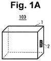
- Fig. 1A is a front perspective view of a wearable sensor device according to a first embodiment of the present invention
- Fig. 1B is a rear perspective view of the wearable sensor device.
- the surface of a wearable sensor device 100 facing an innerwear worn on the wearer is referred to as a back surface
- the surface opposite to the back surface is referred to as a front surface of the wearable sensor device 100.
- the wearable sensor device 100 includes a temperature and humidity sensor 2 (environmental sensor) on the side surface of an outer wall of a sealed housing 1. Further, as will be described later, three snap buttons 3a, 3b, and 3c (first coupling members) for attaching the wearable sensor device 100 to the innerwear are provided on the back surface of the outer wall of the housing 1 facing the innerwear.
- a temperature and humidity sensor 2 environmental sensor
- three snap buttons 3a, 3b, and 3c first coupling members
- Fig. 2 is a diagram illustrating an inner structure of the wearable sensor device 100.
- the wearable sensor device 100 includes a rigid substrate 4a and a flexible substrate 4c for connecting a circuit mounted on the rigid substrate 4a and the temperature and humidity sensor 2 in the sealed housing 1.
- An information acquisition unit 5 for processing environmental information measured by the temperature and humidity sensor 2, a wireless communication unit 6 for wirelessly transmitting the environmental information to an external device, a battery 7, and a power supply circuit 8 for supplying a power supply voltage to the circuit on the rigid substrate 4a and the temperature and humidity sensor 2 using the voltage of the battery 7 as an input are mounted on the rigid substrate 4a.
- the housing 1 is sealed and has waterproofness so that liquids such as sweat and rain do not enter from the outside.
- the housing 1 includes a resin-made upper lid 1a, for example, and similarly a resin-made lower lid 1b.
- a method for ensuring the waterproofness of the housing 1 a method of screwing the upper lid 1a to the lower lid 1b with an O-ring inserted between the upper lid 1a and the lower lid 1b, a method of fixing the upper lid 1a and the lower lid 1b together with an adhesive, a method of ultrasonic-bonding the upper lid 1a and the lower lid 1b, and the like may be used.
- the temperature and humidity sensor 2 is mounted on a rigid substrate 4b.
- the rigid substrate 4b is fixed to the side surface of the outer wall of the housing 1.
- the temperature and humidity sensor 2 includes, for example, a semiconductor chip.
- the semiconductor chip is equipped with a temperature sensor of which the resistance changes with temperature and a humidity sensor that absorbs moisture in the surrounding gas so that the capacitance or resistance changes.
- the temperature and humidity sensor 2 mounted on the rigid substrate 4b is electrically connected to the information acquisition unit 5 and the power supply circuit 8 inside the housing 1 via a flexible wiring and a wiring on the rigid substrate 4a.
- the flexible wiring for example, the flexible substrate 4c can be used.
- the rigid substrates 4a and 4b and the flexible substrate 4c are integrated to form a rigid flexible substrate.
- the information acquisition unit 5, the wireless communication unit 6, the battery 7, and the power supply circuit 8 are mounted on the rigid substrate 4a
- the temperature and humidity sensor 2 is mounted on the rigid substrate 4b
- the rigid substrate 4a and the rigid substrate 4b are electrically connected by the flexible substrate 4c.
- the rigid substrate 4a is fixed to an inner wall surface of the lower lid 1b.
- the rigid substrate 4b is fixed to the side surface of an outer wall of the lower lid 1b.
- the flexible substrate 4c is sandwiched between the upper lid 1a and the lower lid 1b, and the upper lid 1a and the lower lid 1b are attached by methods such as screwing, adhesion, or ultrasonic bonding.
- a resin-made protective member 9 may be provided around the temperature and humidity sensor 2.
- the protective member 9 plays a role of preventing the temperature and humidity sensor 2 from colliding with an external object and being damaged, or preventing a person's finger or the like from coming into contact with the surface of the temperature and humidity sensor 2 and contaminating the sensor surface.
- the protective member 9 is fixed to the side surface of the outer wall of the housing 1.
- the protective member 9 is provided with a ventilation hole 90. Since the temperature and humidity sensor 2 can come into contact with the outside air through the ventilation hole 90, it is possible to measure the temperature and humidity of the surrounding air.
- temperature and humidity data (environmental information) measured by the temperature and humidity sensor 2 can be transmitted to the information acquisition unit 5 inside the housing 1 and be processed.
- the temperature and humidity sensor 2 having a built-in AD converter is used, and the measured value of the temperature and humidity is converted into digital data by the AD converter and transmitted to the information acquisition unit 5.
- the configuration of the temperature and humidity sensor 2 is not limited to this embodiment, and an analog-output temperature and humidity sensor may be used.
- an analog signal processing unit or an AD converter may be mounted on the rigid substrate 4a, and the analog signals output from the temperature and humidity sensor 2 may be processed (for example, amplified) by the analog signal processing unit and then converted to digital data by the AD converter and passed to the information acquisition unit 5.
- the metal-made snap buttons 3a, 3b, and 3c are machined in advance as individual parts. Then, the snap buttons 3a, 3b, and 3c are integrated with the lower lid 1b by an insert molding method so that, when the resin-made lower lid 1b is manufactured, convex portions 200a, 200b, and 200c protrude from the lower surface of the outer wall of the lower lid 1b, and the remaining portion is surrounded by the lower lid 1b. In this way, the snap buttons 3a, 3b, and 3c can be fixed to the lower lid 1b while ensuring the waterproofness of the portion to which the snap buttons 3a, 3b, and 3c are fixed.
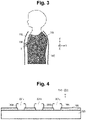
- Fig. 3 is a diagram illustrating a state in which the wearer is wearing the wearable sensor device 100.
- Fig. 4 is an enlarged view of the wear in a state in which the wearer is not wearing the wearable sensor device 100.
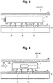
- Figs. 5 and 6 are enlarged views of the wearable sensor device 100 and the wear in a state in which the wearer is wearing the wearable sensor device 100.
- the left-right direction of the wearer's body is the X direction
- the front-back direction is the Y direction
- the vertical direction is the Z direction.
- Figs. 3 , 5, and 6 illustrate a state in which the wearer attaches the wearable sensor device 100 to an innerwear 101 such as a T-shirt, and wears an outerwear 102 on the innerwear 101.
- Fig. 5 illustrates a state in which a portion between the outerwear 102 and the innerwear 101 is viewed from the wearer's head.
- Fig. 6 illustrates a state in which a portion between the outerwear 102 and the innerwear 101 is viewed from the left side of the wearer's body.
- the protective member 9 is not illustrated.
- the innerwear 101 is provided with snap buttons 104a, 104b, and 104c (second coupling member) provided so that concave portions 201a, 201b, and 201c are exposed to the surface opposite to the surface in contact with a wearer's skin 103.
- the convex portions of the male snap buttons 3a, 3b, and 3c provided on the wearable sensor device 100 and the concave portions of the female snap buttons 104a, 104b, and 104c provided on the innerwear 101 are fitted.
- the wearable sensor device 100 can be easily attached to the innerwear 101.
- the wearable sensor device 100 and the innerwear 101 form a monitoring system that measures ambient environmental information around the wearer.
- the wearable sensor device 100 has a thickness of, for example, about 5 mm to 10 mm, it is possible to measure ambient environmental information such as temperature and humidity around a human body without interfering with the movement of the wearer. Further, since the snap buttons 3a, 3b, and 3c are detachably connectable to the snap buttons 104a, 104b, and 104c, when the innerwear 101 is attempted to be washed, the wearable sensor device 100 can be removed and only the innerwear 101 is washed.
- the wearable sensor device 100 is provided between the innerwear 101 and the outerwear 102.
- the temperature and humidity sensor 2 is provided on the side surface of the outer wall of the wearable sensor device 100. Since the back surface of the outer wall provided with the snap buttons 3a, 3b, and 3c of the wearable sensor device 100 and the side surface of the outer wall provided with the temperature and humidity sensor 2 are substantially orthogonal to each other, the temperature and humidity sensor 2 is arranged on a surface near the wearer's body surface, which is substantially orthogonal to the body surface, when the wearable sensor device 100 is attached to the innerwear 101.
- the temperature and humidity sensor 2 faces the space formed between the innerwear 101 and the outerwear 102, and can measure the environmental information of this space.
- the temperature and humidity sensor 2 is arranged on the same surface as or the surface opposite to the snap buttons 3a, 3b, and 3c of the wearable sensor device 100, the air permeability around the temperature and humidity sensor 2 is reduced when the wearable sensor device 100 is attached to the innerwear 101. As a result, the temperature and humidity sensor 2 measures information different from the original ambient environmental information around the wearer.
- the temperature and humidity sensor 2 is arranged on a surface substantially orthogonal to the wearer's body surface as in the present embodiment, the problem of reduced air permeability can be solved.
- the temperature and humidity sensor 2 is arranged on the surface of the housing 1 that faces the wearer's body in the left-right direction when the wearer is in a standing posture.
- the temperature and humidity sensor 2 is arranged on the surface of the housing 1 facing upward when the wearer is in a standing posture, sweat adheres to the temperature and humidity sensor 2 and its surroundings, and cases where the humidity is measured high are likely to occur. Therefore, by arranging the temperature and humidity sensor 2 on the surface of the housing 1 other than the surface facing upward when the wearer is in the standing posture, it is possible to avoid the problem that the measurement is inaccurate due to the adhesion of sweat or the like.
- the air between the innerwear 101 and the outerwear 102 is ventilated with the outside air by a lower opening and an upper opening of the outerwear 102.
- Airflow mainly in the vertical direction is generated between the innerwear 101 and the outerwear 102 to ventilate the air.
- Arrow 105 in Fig. 6 indicates the airflow between the innerwear 101 and the outerwear 102.
- the temperature and humidity sensor 2 is arranged on the surface of the housing 1 facing downward when the wearer is in the standing posture, information different from the original ambient environmental information around the wearer is measured.
- the temperature and humidity sensor 2 By arranging the temperature and humidity sensor 2 on the surface of the housing 1 facing the left side of the wearer's body when the wearer is in the standing posture as in the present embodiment, air flows around the temperature and humidity sensor 2 without the airflow being blocked between the innerwear 101 and the outerwear 102. As a result, the temperature and humidity sensor 2 can measure the original ambient environmental information around the wearer.
- the temperature and humidity sensor 2 is arranged on the surface of the housing 1 facing the left side of the wearer's body when the wearer is in the standing posture.
- the temperature and humidity sensor 2 may naturally be arranged on the surface of the housing 1 facing the right side of the wearer's body.
- the information acquisition unit 5 includes a memory 50 for storing information.
- the information acquisition unit 5 delivers the temperature and humidity data measured by the temperature and humidity sensor 2 to the wireless communication unit 6. At this time, naturally, the information acquisition unit 5 may temporarily store the temperature and humidity data in the memory 50 and deliver the temperature and humidity data to the wireless communication unit 6 when the timing to transmit the temperature and humidity data comes.
- the wireless communication unit 6 wirelessly transmits the temperature and humidity data measured by the temperature and humidity sensor 2 from an antenna 60 to an external device.
- An example of a destination external device is a smartphone possessed by the wearer.
- the information acquisition unit 5 and the wireless communication unit 6 are described as separate blocks in Fig. 7 , one semiconductor chip having the functions of the information acquisition unit 5 and the wireless communication unit 6 may be used.
- the snap buttons 3a, 3b, and 3c are arranged in a non-point-symmetry with respect to the surface of the housing 1 on which they are provided (there is no symmetry point on the surface of the housing 1).
- the snap buttons 3a, 3b, and 3c are arranged one by one at each vertex position of the isosceles triangle (excluding the equilateral triangle) in a plan view. Therefore, the snap buttons 104a, 104b, and 104c that fit with the snap buttons 3a, 3b, and 3c are also arranged one by one at each vertex position of the isosceles triangle (excluding the equilateral triangles) in the plan view on the surface of the innerwear 101.
- the snap buttons 3a, 3b, and 3c and the snap buttons 104a, 104b, and 104c can be correctly fitted, and the temperature and humidity sensor 2 can be prevented from being mounted in the wrong direction.
- Fig. 8A is a front view of a wearable sensor device according to the second embodiment of the present invention.
- Fig. 8B is a rear view of the wearable sensor device.
- the left-right direction of the wearer's body is the X direction
- the front-back direction is the Y direction
- the vertical direction is the Z direction, as in the first embodiment.
- a circuit configuration of a wearable sensor device 100a is the same as that of the first embodiment.
- the temperature and humidity sensor 2 is arranged on the surface of a housing 10 facing in a diagonally downward direction of the wearer's body when the wearable sensor device 100a is attached to the wear worn on the wearer and the wearer is in a standing posture. Due to such an arrangement, in the present embodiment, the possibility of sweat adhering to the temperature and humidity sensor 2 or the periphery thereof can be reduced as compared with the case where the temperature and humidity sensor 2 is arranged on the surface of the housing 10 facing the left or right side of the wearer's body as in the first embodiment. Further, in the present embodiment, it is possible to avoid the airflow around the temperature and humidity sensor 2 from being blocked and becoming stagnant as in the case where the temperature and humidity sensor 2 is arranged on the surface of the housing 10 facing downward when the wearer is in the standing posture.
- two snap buttons 3a and 3b are arranged on the back surface of the wearable sensor device 100a.
- the wearable sensor device 100a may be attached to the wear in an upside-down state.
- the housing 10 has an asymmetrical shape. Specifically, the housing 10 narrows from top to bottom. By making the housing 10 asymmetrical in this way, it becomes easy to prevent the wearable sensor device 100a from being attached in a wrong direction, and urge the temperature and humidity sensor 2 to be attached so as to face diagonally downward of the wearer's body.
- a mark indicating the vertical direction of the wearable sensor device 100a may be provided on the surface of the housing.
- a mark or the like indicating the direction of wearing may be provided on the wear to which the wearable sensor device 100a is attached.
- a snap button is used as a coupling member of the wearable sensor device 100 or 100a to the wear
- a coupling member such as, for example, a magnet, a clip, or the Magic Tape (registered trademark) may be used.
- the wearable sensor device 100 or 100a can be attached to the wear using these coupling members.
- a pocket may be provided on the wear side for attachment of the wearable sensor device instead of a coupling member provided on the wearable sensor device itself.
- a patch or the like that can be adhered to the skin may be provided on the back surface of the wearable sensor device 100 or 100a so that the wearable sensor device 100 or 100a can be directly attached to the wearer's body surface instead of a wear. Further, the wearable sensor device 100 or 100a may be integrated with the wear without being detachably attached thereto.
- the wearable sensor device 100 or 100a can be attached to various wears such as a T-shirt, a tank top, a belly band, a belt around the chest, trousers, an underwear, and an outerwear.
- the wearable sensor device 100 or 100a may also be attached to socks, a hat, a helmet and the like.
- the wearable sensor devices 100 and 100a are intended to monitor the ambient environmental information around a living body, the devices may be worn on an animal or the like without being limited to a person.
- an example of a temperature and humidity sensor is illustrated as an environmental sensor.
- an environmental sensor such as a temperature sensor alone, a humidity sensor alone, a barometric pressure sensor, or a gas sensor may be used.
- a composite sensor in which a number of these sensors are combined may be used as an environmental sensor.
- the information acquisition unit 5 may store the measured environmental information in the memory 50.
- the wearable sensor device can be removed from the wear after the measurement, and the environmental information stored in the memory 50 can be read by wire.
- the environmental information stored in the memory 50 can be read by wire.
- a structure in which the rigid substrate 4a and the flexible substrate 4b are covered and sealed with the box-shaped housing 1 is illustrated as an example, but the present invention is not limited thereto.
- a resin or the like may be poured around the rigid substrate 4a, the flexible substrate 4b, and the snap buttons 3a, 3b, and 3c to cure the resin and achieve sealing.
- the temperature and humidity sensor 2 is mounted on the rigid substrate 4b, and the rigid substrate 4b is fixed to the outer wall surface of the housing 1 or 10, but the present invention is not limited thereto.
- the temperature and humidity sensor 2 may be provided to be separated from the outer wall surface so that the sensor surface 20 of the temperature and humidity sensor 2 is parallel to the outer wall surface of the housing 1 or 10.
- support members 11a and 11b that support the rigid substrate 4b may be provided on the outer wall surface of the housing 1 or 10 so that the rigid substrate 4b on which the temperature and humidity sensor 2 is mounted is provided on the outer wall surface of the housing 1 or 10 with a space therebetween. In this way, the temperature and humidity sensor 2 can be provided to be separated from the outer wall surface by the support members 11a and 11b.
- the software functions of the information acquisition unit 5 and the wireless communication unit 6 can be realized by a computer provided with a CPU (Central Processing Unit), a storage device, and an interface, and a program that controls these hardware resources.
- a computer provided with a CPU (Central Processing Unit), a storage device, and an interface, and a program that controls these hardware resources.
- the computer includes a CPU 300, a storage device 301, and an interface device (I/F) 302.
- the interface device 302 is connected to hardware components including the temperature and humidity sensor 2 and the wireless communication unit 6.
- a program for realizing a monitoring method of the present invention is stored in the storage device 301.
- the CPU 300 executes the process described in the first and second embodiments according to the program stored in the storage device 301.
- the present invention can be applied to a technique for measuring environmental information.
Landscapes
- Engineering & Computer Science (AREA)
- Life Sciences & Earth Sciences (AREA)
- Physics & Mathematics (AREA)
- Health & Medical Sciences (AREA)
- General Physics & Mathematics (AREA)
- Theoretical Computer Science (AREA)
- Computer Hardware Design (AREA)
- Medical Informatics (AREA)
- Surgery (AREA)
- Veterinary Medicine (AREA)
- Public Health (AREA)
- General Health & Medical Sciences (AREA)
- Animal Behavior & Ethology (AREA)
- Molecular Biology (AREA)
- Heart & Thoracic Surgery (AREA)
- Biomedical Technology (AREA)
- Pathology (AREA)
- Biophysics (AREA)
- General Engineering & Computer Science (AREA)
- Human Computer Interaction (AREA)
- Environmental & Geological Engineering (AREA)
- Signal Processing (AREA)
- Computer Networks & Wireless Communication (AREA)
- Power Engineering (AREA)
- Biodiversity & Conservation Biology (AREA)
- Atmospheric Sciences (AREA)
- Ecology (AREA)
- Environmental Sciences (AREA)
- Measuring And Recording Apparatus For Diagnosis (AREA)
- Arrangements For Transmission Of Measured Signals (AREA)
- Testing Or Calibration Of Command Recording Devices (AREA)
Abstract
Description
- The present invention relates to a wearable sensor device and a monitoring system that measure ambient environmental information around a living body.
- It is important to monitor environmental information for physical condition management such as prevention of heat stroke in hot weather.
- For example, a heat index meter conventionally used for preventing heat stroke measures a black bulb temperature, a wet bulb temperature, and a dry bulb temperature to obtain a heat index (see Non-Patent Literature 1). Non-Patent
Literature 1 discloses a method using the heat index as a guideline for action, such as avoiding going out or strenuous work when the heat index is relatively high. - Conventional heat index meters are generally configured as relatively large devices and it is difficult to place them in any given location. For example, the heat index released by the Ministry of the Environment is a value that represents a wide area.
- However, the heat load actually experienced by an individual is greatly affected by the local environment. For example, the environment varies greatly depending on where each person is, such as outdoors or indoors, in sunshine or shade, and on lawn or concrete. Moreover, even in the same place, the influence of radiation from, for example, the ground differs greatly from a tall adult to a short child. Furthermore, the environment around a human body changes greatly depending on the clothes that the person is wearing, the kinetic condition, and the sweating condition.
- Therefore, a method is conceivable in which a person who wants to manage his or her physical condition carries or wears an environmental sensor to monitor the environment around the human body. However, conventional environmental sensors have problems such as inconvenience in carrying, the inability to perform accurate measurement when sweat adheres to the sensor, and the inability to accurately measure original ambient environmental information around a human body if air permeability is obstructed due to attachment of an environmental sensor.
- Non-Patent Literature 1: JuYoun Kwon, Ken Parsons, "Evaluation of the Wet Bulb Globe Temperature (WBGT) Index for Digital Fashion Application in Outdoor Environments", Journal of the Ergonomics Society of Korea, 36(1), pp.23-36, 2017
- The present invention has been made to solve the above-mentioned problems, and an object of the present invention is to enable ambient environmental information around a living body to be measured easily, stably, and accurately.
- A wearable sensor device of the present invention includes an environmental sensor configured to measure ambient environmental information around a living body, wherein
the environmental sensor is provided on an outer wall surface of a housing or provided to be separated from the outer wall surface, the outer wall surface facing a left or right side or diagonally downward when the wearable sensor device is attached to the living body and the living body is in a standing posture. - According to the present invention, the environmental sensor is provided on the outer wall surface of the housing facing a left or right side or diagonally downward of the living body when the living body is in the standing posture, or is provided to be separated from the outer wall surface. This makes it possible to measure local ambient environmental information around the living body easily and stably.
-
- [
Fig. 1A] Fig. 1A is a front perspective view of a wearable sensor device according to a first embodiment of the present invention. - [
Fig. 1B] Fig. 1B is a rear perspective view of the wearable sensor device according to the first embodiment of the present invention. - [
Fig. 2] Fig. 2 is a diagram illustrating an inner structure of the wearable sensor device according to the first embodiment of the present invention. - [
Fig. 3] Fig. 3 is a diagram illustrating a state in which a wearer is wearing the wearable sensor device in the first embodiment of the present invention. - [
Fig. 4] Fig. 4 is an enlarged view of the wear in a state in which the wearer is not wearing the wearable sensor device. - [
Fig. 5] Fig. 5 is an enlarged view of the wearable sensor device and the wear in a state in which the wearer is wearing the wearable sensor device. - [
Fig. 6] Fig. 6 is an enlarged view of the wearable sensor device and the wear in a state in which the wearer is wearing the wearable sensor device. - [
Fig. 7] Fig. 7 is a block diagram illustrating a circuit configuration of the wearable sensor device according to the first embodiment of the present invention. - [
Fig. 8A] Fig. 8A is a front view of a wearable sensor device according to a second embodiment of the present invention. - [
Fig. 8B] Fig. 8B is a rear view of the wearable sensor device according to the second embodiment of the present invention. - [
Fig. 9] Fig. 9 is a diagram illustrating another method of fixing a temperature and humidity sensor according to the first and second embodiments of the present invention. - [
Fig. 10] Fig. 10 is a block diagram illustrating a configuration example of a computer that realizes the wearable sensor device according to the first and second embodiments of the present invention. - Hereinafter, preferred embodiments of the present invention will be described in detail with reference to the drawings.
-
Fig. 1A is a front perspective view of a wearable sensor device according to a first embodiment of the present invention, andFig. 1B is a rear perspective view of the wearable sensor device. Here, the surface of awearable sensor device 100 facing an innerwear worn on the wearer is referred to as a back surface, and the surface opposite to the back surface is referred to as a front surface of thewearable sensor device 100. - The
wearable sensor device 100 includes a temperature and humidity sensor 2 (environmental sensor) on the side surface of an outer wall of a sealedhousing 1. Further, as will be described later, threesnap buttons wearable sensor device 100 to the innerwear are provided on the back surface of the outer wall of thehousing 1 facing the innerwear. -
Fig. 2 is a diagram illustrating an inner structure of thewearable sensor device 100. Thewearable sensor device 100 includes arigid substrate 4a and aflexible substrate 4c for connecting a circuit mounted on therigid substrate 4a and the temperature andhumidity sensor 2 in the sealedhousing 1. - An
information acquisition unit 5 for processing environmental information measured by the temperature andhumidity sensor 2, awireless communication unit 6 for wirelessly transmitting the environmental information to an external device, abattery 7, and apower supply circuit 8 for supplying a power supply voltage to the circuit on therigid substrate 4a and the temperature andhumidity sensor 2 using the voltage of thebattery 7 as an input are mounted on therigid substrate 4a. - The
housing 1 is sealed and has waterproofness so that liquids such as sweat and rain do not enter from the outside. Thehousing 1 includes a resin-made upper lid 1a, for example, and similarly a resin-madelower lid 1b. As a well-known method for ensuring the waterproofness of thehousing 1, a method of screwing the upper lid 1a to thelower lid 1b with an O-ring inserted between the upper lid 1a and thelower lid 1b, a method of fixing the upper lid 1a and thelower lid 1b together with an adhesive, a method of ultrasonic-bonding the upper lid 1a and thelower lid 1b, and the like may be used. - The temperature and
humidity sensor 2 is mounted on arigid substrate 4b. Therigid substrate 4b is fixed to the side surface of the outer wall of thehousing 1. The temperature andhumidity sensor 2 includes, for example, a semiconductor chip. The semiconductor chip is equipped with a temperature sensor of which the resistance changes with temperature and a humidity sensor that absorbs moisture in the surrounding gas so that the capacitance or resistance changes. The temperature andhumidity sensor 2 mounted on therigid substrate 4b is electrically connected to theinformation acquisition unit 5 and thepower supply circuit 8 inside thehousing 1 via a flexible wiring and a wiring on therigid substrate 4a. As the flexible wiring, for example, theflexible substrate 4c can be used. - The
rigid substrates flexible substrate 4c are integrated to form a rigid flexible substrate. As described above, theinformation acquisition unit 5, thewireless communication unit 6, thebattery 7, and thepower supply circuit 8 are mounted on therigid substrate 4a, the temperature andhumidity sensor 2 is mounted on therigid substrate 4b, and therigid substrate 4a and therigid substrate 4b are electrically connected by theflexible substrate 4c. - The
rigid substrate 4a is fixed to an inner wall surface of thelower lid 1b. Therigid substrate 4b is fixed to the side surface of an outer wall of thelower lid 1b. With therigid substrates lower lid 1b, theflexible substrate 4c is sandwiched between the upper lid 1a and thelower lid 1b, and the upper lid 1a and thelower lid 1b are attached by methods such as screwing, adhesion, or ultrasonic bonding. - Further, as illustrated in
Fig. 2 , for example, a resin-madeprotective member 9 may be provided around the temperature andhumidity sensor 2. Theprotective member 9 plays a role of preventing the temperature andhumidity sensor 2 from colliding with an external object and being damaged, or preventing a person's finger or the like from coming into contact with the surface of the temperature andhumidity sensor 2 and contaminating the sensor surface. Theprotective member 9 is fixed to the side surface of the outer wall of thehousing 1. Theprotective member 9 is provided with aventilation hole 90. Since the temperature andhumidity sensor 2 can come into contact with the outside air through theventilation hole 90, it is possible to measure the temperature and humidity of the surrounding air. - In this way, temperature and humidity data (environmental information) measured by the temperature and
humidity sensor 2 can be transmitted to theinformation acquisition unit 5 inside thehousing 1 and be processed. - In the present embodiment, the temperature and
humidity sensor 2 having a built-in AD converter is used, and the measured value of the temperature and humidity is converted into digital data by the AD converter and transmitted to theinformation acquisition unit 5. The configuration of the temperature andhumidity sensor 2 is not limited to this embodiment, and an analog-output temperature and humidity sensor may be used. In this case, an analog signal processing unit or an AD converter may be mounted on therigid substrate 4a, and the analog signals output from the temperature andhumidity sensor 2 may be processed (for example, amplified) by the analog signal processing unit and then converted to digital data by the AD converter and passed to theinformation acquisition unit 5. - The metal-made
snap buttons snap buttons lower lid 1b by an insert molding method so that, when the resin-madelower lid 1b is manufactured,convex portions lower lid 1b, and the remaining portion is surrounded by thelower lid 1b. In this way, thesnap buttons lower lid 1b while ensuring the waterproofness of the portion to which thesnap buttons -
Fig. 3 is a diagram illustrating a state in which the wearer is wearing thewearable sensor device 100.Fig. 4 is an enlarged view of the wear in a state in which the wearer is not wearing thewearable sensor device 100.Figs. 5 and 6 are enlarged views of thewearable sensor device 100 and the wear in a state in which the wearer is wearing thewearable sensor device 100. InFigs. 3 to 6 , the left-right direction of the wearer's body is the X direction, the front-back direction is the Y direction, and the vertical direction is the Z direction. -
Figs. 3 ,5, and 6 illustrate a state in which the wearer attaches thewearable sensor device 100 to aninnerwear 101 such as a T-shirt, and wears anouterwear 102 on theinnerwear 101.Fig. 5 illustrates a state in which a portion between theouterwear 102 and theinnerwear 101 is viewed from the wearer's head.Fig. 6 illustrates a state in which a portion between theouterwear 102 and theinnerwear 101 is viewed from the left side of the wearer's body. In addition, inFigs. 3 ,5, and 6 , theprotective member 9 is not illustrated. - The
innerwear 101 is provided withsnap buttons concave portions skin 103. - As illustrated in
Figs. 5 and 6 , the convex portions of themale snap buttons wearable sensor device 100 and the concave portions of thefemale snap buttons innerwear 101 are fitted. As a result, thewearable sensor device 100 can be easily attached to theinnerwear 101. When thewearable sensor device 100 is attached to theinnerwear 101, thewearable sensor device 100 and theinnerwear 101 form a monitoring system that measures ambient environmental information around the wearer. - Since the
wearable sensor device 100 has a thickness of, for example, about 5 mm to 10 mm, it is possible to measure ambient environmental information such as temperature and humidity around a human body without interfering with the movement of the wearer. Further, since thesnap buttons snap buttons innerwear 101 is attempted to be washed, thewearable sensor device 100 can be removed and only theinnerwear 101 is washed. - When the wearer is wearing the
outerwear 102 on theinnerwear 101 as illustrated inFigs. 3 ,5, and 6 , thewearable sensor device 100 is provided between the innerwear 101 and theouterwear 102. - A gap is formed between the innerwear 101 and the
outerwear 102 due to the deflection of the wears 101 and 102 and the thickness of thewearable sensor device 100. As described above, the temperature andhumidity sensor 2 is provided on the side surface of the outer wall of thewearable sensor device 100. Since the back surface of the outer wall provided with thesnap buttons wearable sensor device 100 and the side surface of the outer wall provided with the temperature andhumidity sensor 2 are substantially orthogonal to each other, the temperature andhumidity sensor 2 is arranged on a surface near the wearer's body surface, which is substantially orthogonal to the body surface, when thewearable sensor device 100 is attached to theinnerwear 101. - Therefore, the temperature and
humidity sensor 2 faces the space formed between the innerwear 101 and theouterwear 102, and can measure the environmental information of this space. - If the temperature and
humidity sensor 2 is arranged on the same surface as or the surface opposite to thesnap buttons wearable sensor device 100, the air permeability around the temperature andhumidity sensor 2 is reduced when thewearable sensor device 100 is attached to theinnerwear 101. As a result, the temperature andhumidity sensor 2 measures information different from the original ambient environmental information around the wearer. When the temperature andhumidity sensor 2 is arranged on a surface substantially orthogonal to the wearer's body surface as in the present embodiment, the problem of reduced air permeability can be solved. - As illustrated in
Figs. 3 ,5, and 6 , the temperature andhumidity sensor 2 is arranged on the surface of thehousing 1 that faces the wearer's body in the left-right direction when the wearer is in a standing posture. - If the temperature and
humidity sensor 2 is arranged on the surface of thehousing 1 facing upward when the wearer is in a standing posture, sweat adheres to the temperature andhumidity sensor 2 and its surroundings, and cases where the humidity is measured high are likely to occur. Therefore, by arranging the temperature andhumidity sensor 2 on the surface of thehousing 1 other than the surface facing upward when the wearer is in the standing posture, it is possible to avoid the problem that the measurement is inaccurate due to the adhesion of sweat or the like. - Further, the air between the innerwear 101 and the
outerwear 102 is ventilated with the outside air by a lower opening and an upper opening of theouterwear 102. Airflow mainly in the vertical direction is generated between the innerwear 101 and theouterwear 102 to ventilate the air.Arrow 105 inFig. 6 indicates the airflow between the innerwear 101 and theouterwear 102. - On the surface of the
housing 1 facing downward when the wearer is in a standing position, the airflow between the innerwear 101 and theouterwear 102 is blocked by thewearable sensor device 100, and the air is stagnant. Therefore, if the temperature andhumidity sensor 2 is arranged on the surface of thehousing 1 facing downward when the wearer is in the standing posture, information different from the original ambient environmental information around the wearer is measured. - By arranging the temperature and
humidity sensor 2 on the surface of thehousing 1 facing the left side of the wearer's body when the wearer is in the standing posture as in the present embodiment, air flows around the temperature andhumidity sensor 2 without the airflow being blocked between the innerwear 101 and theouterwear 102. As a result, the temperature andhumidity sensor 2 can measure the original ambient environmental information around the wearer. - In
Figs. 3 ,5, and 6 , the temperature andhumidity sensor 2 is arranged on the surface of thehousing 1 facing the left side of the wearer's body when the wearer is in the standing posture. However, the temperature andhumidity sensor 2 may naturally be arranged on the surface of thehousing 1 facing the right side of the wearer's body. - Next, a circuit configuration of the
wearable sensor device 100 will be described with reference toFig. 7 . In the present embodiment, the temperature andhumidity sensor 2 is connected to theinformation acquisition unit 5. Theinformation acquisition unit 5 includes amemory 50 for storing information. - The
information acquisition unit 5 delivers the temperature and humidity data measured by the temperature andhumidity sensor 2 to thewireless communication unit 6. At this time, naturally, theinformation acquisition unit 5 may temporarily store the temperature and humidity data in thememory 50 and deliver the temperature and humidity data to thewireless communication unit 6 when the timing to transmit the temperature and humidity data comes. - The
wireless communication unit 6 wirelessly transmits the temperature and humidity data measured by the temperature andhumidity sensor 2 from anantenna 60 to an external device. An example of a destination external device is a smartphone possessed by the wearer. - Although the
information acquisition unit 5 and thewireless communication unit 6 are described as separate blocks inFig. 7 , one semiconductor chip having the functions of theinformation acquisition unit 5 and thewireless communication unit 6 may be used. - The
snap buttons housing 1 on which they are provided (there is no symmetry point on the surface of the housing 1). In particular, in the present embodiment, thesnap buttons snap buttons snap buttons innerwear 101. With such an arrangement, thesnap buttons snap buttons humidity sensor 2 can be prevented from being mounted in the wrong direction. - Next, a second embodiment of the present invention will be described.
Fig. 8A is a front view of a wearable sensor device according to the second embodiment of the present invention.Fig. 8B is a rear view of the wearable sensor device. InFigs. 8A and 8B , the left-right direction of the wearer's body is the X direction, the front-back direction is the Y direction, and the vertical direction is the Z direction, as in the first embodiment. - A circuit configuration of a
wearable sensor device 100a is the same as that of the first embodiment. In the present embodiment, the temperature andhumidity sensor 2 is arranged on the surface of ahousing 10 facing in a diagonally downward direction of the wearer's body when thewearable sensor device 100a is attached to the wear worn on the wearer and the wearer is in a standing posture. Due to such an arrangement, in the present embodiment, the possibility of sweat adhering to the temperature andhumidity sensor 2 or the periphery thereof can be reduced as compared with the case where the temperature andhumidity sensor 2 is arranged on the surface of thehousing 10 facing the left or right side of the wearer's body as in the first embodiment.
Further, in the present embodiment, it is possible to avoid the airflow around the temperature andhumidity sensor 2 from being blocked and becoming stagnant as in the case where the temperature andhumidity sensor 2 is arranged on the surface of thehousing 10 facing downward when the wearer is in the standing posture. - In order to prevent sweat from adhering to the temperature and
humidity sensor 2 and prevent stagnation of airflow, it is preferable that the surface of thehousing 10 on which the temperature andhumidity sensor 2 is arranged has an angle θ in the range of, for example, θ = 20° to 90° from the vertically downward direction (0°) when thewearable sensor device 100a is attached to the wearer's wear and the wearer is in a standing position. More preferably, by setting the range of θ = 30° to 60°, it is possible to more reliably prevent the adhesion of sweat to the temperature andhumidity sensor 2 and the stagnation of the airflow. - In the present embodiment, two
snap buttons wearable sensor device 100a. When there are twosnap buttons wearable sensor device 100a may be attached to the wear in an upside-down state. In cope with such a problem, in the present embodiment, thehousing 10 has an asymmetrical shape. Specifically, thehousing 10 narrows from top to bottom. By making thehousing 10 asymmetrical in this way, it becomes easy to prevent thewearable sensor device 100a from being attached in a wrong direction, and urge the temperature andhumidity sensor 2 to be attached so as to face diagonally downward of the wearer's body. - Further, in order to prevent the
wearable sensor device 100a from being attached to the wear in an upside-down state, a mark indicating the vertical direction of thewearable sensor device 100a may be provided on the surface of the housing. - Further, a mark or the like indicating the direction of wearing may be provided on the wear to which the
wearable sensor device 100a is attached. - In the first and second embodiments, an example in which a snap button is used as a coupling member of the
wearable sensor device wearable sensor device - Further, a patch or the like that can be adhered to the skin may be provided on the back surface of the
wearable sensor device wearable sensor device wearable sensor device - Further, the
wearable sensor device wearable sensor device - Further, since the
wearable sensor devices - Further, in the first and second embodiments, an example of a temperature and humidity sensor is illustrated as an environmental sensor. However, the present invention is not limited thereto, and an environmental sensor such as a temperature sensor alone, a humidity sensor alone, a barometric pressure sensor, or a gas sensor may be used. Further, a composite sensor in which a number of these sensors are combined may be used as an environmental sensor.
- Further, in the first and second embodiments, an example in which environmental information is transmitted to an external device by the
wireless communication unit 6 is illustrated, but the present invention is not limited thereto. - The
information acquisition unit 5 may store the measured environmental information in thememory 50. In this case, the wearable sensor device can be removed from the wear after the measurement, and the environmental information stored in thememory 50 can be read by wire. Naturally, in the case of reading the information by wire, it is necessary to provide a reading connector electrically connected to theinformation acquisition unit 5 in the housing. - Further, in the first and second embodiments, a structure in which the
rigid substrate 4a and theflexible substrate 4b are covered and sealed with the box-shapedhousing 1 is illustrated as an example, but the present invention is not limited thereto. For example, a resin or the like may be poured around therigid substrate 4a, theflexible substrate 4b, and thesnap buttons - Further, in the first and second embodiments, the temperature and
humidity sensor 2 is mounted on therigid substrate 4b, and therigid substrate 4b is fixed to the outer wall surface of thehousing Fig. 9 , the temperature andhumidity sensor 2 may be provided to be separated from the outer wall surface so that thesensor surface 20 of the temperature andhumidity sensor 2 is parallel to the outer wall surface of thehousing - Specifically,
support members rigid substrate 4b may be provided on the outer wall surface of thehousing rigid substrate 4b on which the temperature andhumidity sensor 2 is mounted is provided on the outer wall surface of thehousing humidity sensor 2 can be provided to be separated from the outer wall surface by thesupport members - In the configurations of the
wearable sensor devices information acquisition unit 5 and thewireless communication unit 6 can be realized by a computer provided with a CPU (Central Processing Unit), a storage device, and an interface, and a program that controls these hardware resources. A configuration example of this computer is illustrated inFig. 10 . - The computer includes a
CPU 300, astorage device 301, and an interface device (I/F) 302. Theinterface device 302 is connected to hardware components including the temperature andhumidity sensor 2 and thewireless communication unit 6. In such a computer, a program for realizing a monitoring method of the present invention is stored in thestorage device 301. TheCPU 300 executes the process described in the first and second embodiments according to the program stored in thestorage device 301. - The present invention can be applied to a technique for measuring environmental information.
-
- 1, 10
- Housing
- 1a
- Upper lid
- 1b
- Lower lid
- 2
- Temperature and humidity sensor
- 3a to 3c, 104a to 104c
- Snap button
- 4a,
- 4b Rigid substrate
- 4c
- Flexible substrate
- 5
- Information acquisition unit
- 6
- Wireless communication unit
- 7
- Battery
- 8
- Power supply circuit
- 9
- Protective member
- 11a, 11b
- Support member
- 50
- Memory
- 90
- Ventilation hole
- 100, 100a
- Wearable sensor device
- 101
- Innerwear
- 102
- Outerwear
Claims (8)
- A wearable sensor device comprising an environmental sensor configured to measure ambient environmental information around a living body, wherein
the environmental sensor is provided on an outer wall surface of a housing or provided to be separated from the outer wall surface, the outer wall surface facing a left or right side or diagonally downward from the living body when the wearable sensor device is attached to the living body and the living body is in a standing posture. - The wearable sensor device according to claim 1, further comprising a wireless communication unit configured to wirelessly transmit the environmental information to an external device, wherein
the wireless communication unit is provided in the housing that is sealed. - The wearable sensor device according to claim 1 or 2, further comprising a protective member having a ventilation hole around the environmental sensor.
- The wearable sensor device according to any one of claims 1 to 3, wherein
the environmental sensor is provided on the outer wall surface at an angle in a range of 30° to 60° from a vertically downward direction when the wearable sensor device is attached to the living body and the living body is in a standing posture, or is provided to be separated from the outer wall surface. - The wearable sensor device according to any one of claims 1 to 4, further comprising a first coupling member for attaching the wearable sensor device to the living body.
- The wearable sensor device according to claim 5, whereinthe environmental sensor and the first coupling member are provided on respective surfaces of the housing that are substantially orthogonal to each other, andthe environmental sensor is provided on an outer wall surface of the housing or provided to be separated from the outer wall surface, the outer wall surface being substantially orthogonal to a body surface of the living body when the wearable sensor device is attached to the living body.
- A monitoring system comprising:the wearable sensor device according to claim 5 or 6; anda wear to be worn on the living body, whereinthe wear includes a second coupling member provided so as to be fitted with the first coupling member of the wearable sensor device.
- The monitoring system according to claim 7, wherein
the wear is an innerwear in which the second coupling member is provided on a surface opposite to a surface of the innerwear facing the living body.
Applications Claiming Priority (1)
| Application Number | Priority Date | Filing Date | Title |
|---|---|---|---|
| PCT/JP2019/043411 WO2021090386A1 (en) | 2019-11-06 | 2019-11-06 | Wearable sensor device and monitoring system |
Publications (3)
| Publication Number | Publication Date |
|---|---|
| EP4056971A1 true EP4056971A1 (en) | 2022-09-14 |
| EP4056971A4 EP4056971A4 (en) | 2023-08-30 |
| EP4056971B1 EP4056971B1 (en) | 2024-10-09 |
Family
ID=75848093
Family Applications (1)
| Application Number | Title | Priority Date | Filing Date |
|---|---|---|---|
| EP19951725.1A Active EP4056971B1 (en) | 2019-11-06 | 2019-11-06 | Wearable sensor device and monitoring system |
Country Status (7)
| Country | Link |
|---|---|
| US (2) | US12174662B2 (en) |
| EP (1) | EP4056971B1 (en) |
| JP (2) | JPWO2021090386A1 (en) |
| AU (2) | AU2019473186A1 (en) |
| CA (1) | CA3160457A1 (en) |
| ES (1) | ES2991254T3 (en) |
| WO (1) | WO2021090386A1 (en) |
Families Citing this family (1)
| Publication number | Priority date | Publication date | Assignee | Title |
|---|---|---|---|---|
| US12203812B2 (en) * | 2021-03-01 | 2025-01-21 | Copeland Cold Chain Lp | Bracket for temperature sensor |
Family Cites Families (22)
| Publication number | Priority date | Publication date | Assignee | Title |
|---|---|---|---|---|
| JPH04113093U (en) | 1991-03-19 | 1992-10-01 | カシオ計算機株式会社 | watch case |
| JPH0592706U (en) * | 1992-05-19 | 1993-12-17 | ティーディーケイ株式会社 | Humidity detector |
| JPH0715719U (en) * | 1993-08-25 | 1995-03-17 | 株式会社エム・ツー | Clothes with clock |
| IL113790A0 (en) * | 1995-05-19 | 1995-08-31 | Tius Elcon Ltd | Body temperature measuring instrument |
| CA2560323C (en) * | 2004-03-22 | 2014-01-07 | Bodymedia, Inc. | Non-invasive temperature monitoring device |
| JP2006055189A (en) * | 2004-08-17 | 2006-03-02 | Citizen Watch Co Ltd | Activity grasping system |
| JP2007073020A (en) * | 2005-09-08 | 2007-03-22 | Ee Ii Syst Kk | System for transmitting measurement signal for humidity and temperature sensor via wireless lan |
| US8818478B2 (en) * | 2011-03-31 | 2014-08-26 | Adidas Ag | Sensor garment |
| US20160140870A1 (en) | 2013-05-23 | 2016-05-19 | Medibotics Llc | Hand-Held Spectroscopic Sensor with Light-Projected Fiducial Marker for Analyzing Food Composition and Quantity |
| US8994827B2 (en) * | 2012-11-20 | 2015-03-31 | Samsung Electronics Co., Ltd | Wearable electronic device |
| EP3834712A1 (en) | 2014-08-15 | 2021-06-16 | Nonin Medical, Inc | Tissue interface |
| US10154460B1 (en) * | 2015-02-17 | 2018-12-11 | Halo Wearables LLC | Power management for wearable devices |
| ES2914683T3 (en) * | 2015-07-30 | 2022-06-15 | Sanko Tekstil Isletmeleri San Ve Tic As | Electronic Button for Smart Garments |
| JP6682796B2 (en) | 2015-10-09 | 2020-04-15 | タカヤ株式会社 | Sensing type clothing and management system |
| US10096230B2 (en) * | 2016-06-06 | 2018-10-09 | Makusafe Corp | Safety device, system and method of use |
| JP6961917B2 (en) * | 2016-09-26 | 2021-11-05 | 日本電気株式会社 | Connection parts for wearable devices and wearable devices |
| JP6828434B2 (en) * | 2016-12-29 | 2021-02-10 | セイコーエプソン株式会社 | Indicator display and electronic clock |
| JP6844264B2 (en) * | 2017-01-06 | 2021-03-17 | セイコーエプソン株式会社 | Electronic clock |
| EP4257034A1 (en) * | 2017-01-13 | 2023-10-11 | Huawei Technologies Co., Ltd. | Wearable device |
| JP2018143383A (en) * | 2017-03-02 | 2018-09-20 | 学校法人四恩学園 | Clothing-type wearable sensor |
| EP3652627A4 (en) * | 2017-07-14 | 2021-04-14 | Vieconnect SAS | SYSTEMS AND METHODS FOR MONITORING A CLOTHING DEVICE |
| BR112020012446A2 (en) * | 2017-10-18 | 2020-11-24 | Infrasonix Inc. | wearable health monitoring devices and methods of manufacturing and using them |
-
2019
- 2019-11-06 WO PCT/JP2019/043411 patent/WO2021090386A1/en not_active Ceased
- 2019-11-06 EP EP19951725.1A patent/EP4056971B1/en active Active
- 2019-11-06 CA CA3160457A patent/CA3160457A1/en active Pending
- 2019-11-06 US US17/773,959 patent/US12174662B2/en active Active
- 2019-11-06 JP JP2021554455A patent/JPWO2021090386A1/ja active Pending
- 2019-11-06 ES ES19951725T patent/ES2991254T3/en active Active
- 2019-11-06 AU AU2019473186A patent/AU2019473186A1/en not_active Abandoned
-
2023
- 2023-11-01 JP JP2023187737A patent/JP2023181442A/en active Pending
-
2024
- 2024-03-14 AU AU2024201679A patent/AU2024201679B2/en active Active
- 2024-11-13 US US18/945,899 patent/US20250068212A1/en active Pending
Also Published As
| Publication number | Publication date |
|---|---|
| AU2024201679A1 (en) | 2024-04-04 |
| US12174662B2 (en) | 2024-12-24 |
| WO2021090386A1 (en) | 2021-05-14 |
| CA3160457A1 (en) | 2021-05-14 |
| US20250068212A1 (en) | 2025-02-27 |
| AU2019473186A1 (en) | 2022-05-26 |
| US20220382325A1 (en) | 2022-12-01 |
| ES2991254T3 (en) | 2024-12-03 |
| EP4056971B1 (en) | 2024-10-09 |
| JPWO2021090386A1 (en) | 2021-05-14 |
| EP4056971A4 (en) | 2023-08-30 |
| JP2023181442A (en) | 2023-12-21 |
| AU2024201679B2 (en) | 2025-08-14 |
Similar Documents
| Publication | Publication Date | Title |
|---|---|---|
| US20100191072A1 (en) | Button Sensor | |
| EP4056119B1 (en) | Wearable sensor device | |
| US20250068212A1 (en) | Wearable Sensor Device and Monitoring System | |
| US20180070878A1 (en) | Electronic apparatus | |
| US12276552B2 (en) | Wearable environmental sensor device and monitoring system | |
| WO2019220908A1 (en) | Helmet and sensor attachment structure | |
| JP7307619B2 (en) | Clothes with sensors, physical condition management systems, and physical condition management programs | |
| CA3160309C (en) | Wearable sensor device | |
| US12527510B2 (en) | Wearable environmental sensor device | |
| US20220397460A1 (en) | Wearable Environmental Sensor Device | |
| CN112220126A (en) | Novel but gauze mask of real-time detection body temperature | |
| KR102402335B1 (en) | Adhesive band for fixing patch type thermometer and patch type thermometer including the same |
Legal Events
| Date | Code | Title | Description |
|---|---|---|---|
| STAA | Information on the status of an ep patent application or granted ep patent |
Free format text: STATUS: THE INTERNATIONAL PUBLICATION HAS BEEN MADE |
|
| PUAI | Public reference made under article 153(3) epc to a published international application that has entered the european phase |
Free format text: ORIGINAL CODE: 0009012 |
|
| STAA | Information on the status of an ep patent application or granted ep patent |
Free format text: STATUS: REQUEST FOR EXAMINATION WAS MADE |
|
| 17P | Request for examination filed |
Effective date: 20220426 |
|
| AK | Designated contracting states |
Kind code of ref document: A1 Designated state(s): AL AT BE BG CH CY CZ DE DK EE ES FI FR GB GR HR HU IE IS IT LI LT LU LV MC MK MT NL NO PL PT RO RS SE SI SK SM TR |
|
| DAV | Request for validation of the european patent (deleted) | ||
| DAX | Request for extension of the european patent (deleted) | ||
| REG | Reference to a national code |
Ref country code: DE Ref legal event code: R079 Ipc: G01K0001140000 Ref country code: DE Ref legal event code: R079 Ref document number: 602019060360 Country of ref document: DE Free format text: PREVIOUS MAIN CLASS: G01K0007000000 Ipc: G01K0001140000 |
|
| A4 | Supplementary search report drawn up and despatched |
Effective date: 20230727 |
|
| RIC1 | Information provided on ipc code assigned before grant |
Ipc: A61B 5/01 20060101ALI20230721BHEP Ipc: A61B 5/00 20060101ALI20230721BHEP Ipc: G01K 1/024 20210101ALI20230721BHEP Ipc: G01K 1/08 20210101ALI20230721BHEP Ipc: G01K 1/14 20210101AFI20230721BHEP |
|
| REG | Reference to a national code |
Ref country code: DE Ref legal event code: R079 Free format text: PREVIOUS MAIN CLASS: G01K0001140000 Ipc: G01W0001170000 Ref country code: DE Ref legal event code: R079 Ref document number: 602019060360 Country of ref document: DE Free format text: PREVIOUS MAIN CLASS: G01K0001140000 Ipc: G01W0001170000 |
|
| GRAP | Despatch of communication of intention to grant a patent |
Free format text: ORIGINAL CODE: EPIDOSNIGR1 |
|
| STAA | Information on the status of an ep patent application or granted ep patent |
Free format text: STATUS: GRANT OF PATENT IS INTENDED |
|
| INTG | Intention to grant announced |
Effective date: 20240426 |
|
| RIC1 | Information provided on ipc code assigned before grant |
Ipc: A61B 5/01 20060101ALI20240412BHEP Ipc: A61B 5/00 20060101ALI20240412BHEP Ipc: G01K 1/024 20210101ALI20240412BHEP Ipc: G01K 1/08 20210101ALI20240412BHEP Ipc: G01K 1/14 20210101ALI20240412BHEP Ipc: G01W 1/17 20060101AFI20240412BHEP |
|
| GRAS | Grant fee paid |
Free format text: ORIGINAL CODE: EPIDOSNIGR3 |
|
| GRAA | (expected) grant |
Free format text: ORIGINAL CODE: 0009210 |
|
| STAA | Information on the status of an ep patent application or granted ep patent |
Free format text: STATUS: THE PATENT HAS BEEN GRANTED |
|
| AK | Designated contracting states |
Kind code of ref document: B1 Designated state(s): AL AT BE BG CH CY CZ DE DK EE ES FI FR GB GR HR HU IE IS IT LI LT LU LV MC MK MT NL NO PL PT RO RS SE SI SK SM TR |
|
| REG | Reference to a national code |
Ref country code: CH Ref legal event code: EP |
|
| REG | Reference to a national code |
Ref country code: DE Ref legal event code: R096 Ref document number: 602019060360 Country of ref document: DE |
|
| REG | Reference to a national code |
Ref country code: IE Ref legal event code: FG4D |
|
| REG | Reference to a national code |
Ref country code: ES Ref legal event code: FG2A Ref document number: 2991254 Country of ref document: ES Kind code of ref document: T3 Effective date: 20241203 |
|
| REG | Reference to a national code |
Ref country code: LT Ref legal event code: MG9D |
|
| REG | Reference to a national code |
Ref country code: NL Ref legal event code: MP Effective date: 20241009 |
|
| REG | Reference to a national code |
Ref country code: AT Ref legal event code: MK05 Ref document number: 1731156 Country of ref document: AT Kind code of ref document: T Effective date: 20241009 |
|
| PG25 | Lapsed in a contracting state [announced via postgrant information from national office to epo] |
Ref country code: NL Free format text: LAPSE BECAUSE OF FAILURE TO SUBMIT A TRANSLATION OF THE DESCRIPTION OR TO PAY THE FEE WITHIN THE PRESCRIBED TIME-LIMIT Effective date: 20241009 |
|
| PG25 | Lapsed in a contracting state [announced via postgrant information from national office to epo] |
Ref country code: NL Free format text: LAPSE BECAUSE OF FAILURE TO SUBMIT A TRANSLATION OF THE DESCRIPTION OR TO PAY THE FEE WITHIN THE PRESCRIBED TIME-LIMIT Effective date: 20241009 |
|
| PG25 | Lapsed in a contracting state [announced via postgrant information from national office to epo] |
Ref country code: IS Free format text: LAPSE BECAUSE OF FAILURE TO SUBMIT A TRANSLATION OF THE DESCRIPTION OR TO PAY THE FEE WITHIN THE PRESCRIBED TIME-LIMIT Effective date: 20250209 Ref country code: PT Free format text: LAPSE BECAUSE OF FAILURE TO SUBMIT A TRANSLATION OF THE DESCRIPTION OR TO PAY THE FEE WITHIN THE PRESCRIBED TIME-LIMIT Effective date: 20250210 Ref country code: HR Free format text: LAPSE BECAUSE OF FAILURE TO SUBMIT A TRANSLATION OF THE DESCRIPTION OR TO PAY THE FEE WITHIN THE PRESCRIBED TIME-LIMIT Effective date: 20241009 |
|
| PG25 | Lapsed in a contracting state [announced via postgrant information from national office to epo] |
Ref country code: FI Free format text: LAPSE BECAUSE OF FAILURE TO SUBMIT A TRANSLATION OF THE DESCRIPTION OR TO PAY THE FEE WITHIN THE PRESCRIBED TIME-LIMIT Effective date: 20241009 |
|
| PG25 | Lapsed in a contracting state [announced via postgrant information from national office to epo] |
Ref country code: BG Free format text: LAPSE BECAUSE OF FAILURE TO SUBMIT A TRANSLATION OF THE DESCRIPTION OR TO PAY THE FEE WITHIN THE PRESCRIBED TIME-LIMIT Effective date: 20241009 |
|
| PG25 | Lapsed in a contracting state [announced via postgrant information from national office to epo] |
Ref country code: NO Free format text: LAPSE BECAUSE OF FAILURE TO SUBMIT A TRANSLATION OF THE DESCRIPTION OR TO PAY THE FEE WITHIN THE PRESCRIBED TIME-LIMIT Effective date: 20250109 |
|
| PG25 | Lapsed in a contracting state [announced via postgrant information from national office to epo] |
Ref country code: LV Free format text: LAPSE BECAUSE OF FAILURE TO SUBMIT A TRANSLATION OF THE DESCRIPTION OR TO PAY THE FEE WITHIN THE PRESCRIBED TIME-LIMIT Effective date: 20241009 Ref country code: AT Free format text: LAPSE BECAUSE OF FAILURE TO SUBMIT A TRANSLATION OF THE DESCRIPTION OR TO PAY THE FEE WITHIN THE PRESCRIBED TIME-LIMIT Effective date: 20241009 Ref country code: GR Free format text: LAPSE BECAUSE OF FAILURE TO SUBMIT A TRANSLATION OF THE DESCRIPTION OR TO PAY THE FEE WITHIN THE PRESCRIBED TIME-LIMIT Effective date: 20250110 |
|
| PG25 | Lapsed in a contracting state [announced via postgrant information from national office to epo] |
Ref country code: PL Free format text: LAPSE BECAUSE OF FAILURE TO SUBMIT A TRANSLATION OF THE DESCRIPTION OR TO PAY THE FEE WITHIN THE PRESCRIBED TIME-LIMIT Effective date: 20241009 |
|
| PG25 | Lapsed in a contracting state [announced via postgrant information from national office to epo] |
Ref country code: RS Free format text: LAPSE BECAUSE OF FAILURE TO SUBMIT A TRANSLATION OF THE DESCRIPTION OR TO PAY THE FEE WITHIN THE PRESCRIBED TIME-LIMIT Effective date: 20250109 |
|
| REG | Reference to a national code |
Ref country code: CH Ref legal event code: PL |
|
| PG25 | Lapsed in a contracting state [announced via postgrant information from national office to epo] |
Ref country code: SM Free format text: LAPSE BECAUSE OF FAILURE TO SUBMIT A TRANSLATION OF THE DESCRIPTION OR TO PAY THE FEE WITHIN THE PRESCRIBED TIME-LIMIT Effective date: 20241009 |
|
| PG25 | Lapsed in a contracting state [announced via postgrant information from national office to epo] |
Ref country code: MC Free format text: LAPSE BECAUSE OF FAILURE TO SUBMIT A TRANSLATION OF THE DESCRIPTION OR TO PAY THE FEE WITHIN THE PRESCRIBED TIME-LIMIT Effective date: 20241009 |
|
| PG25 | Lapsed in a contracting state [announced via postgrant information from national office to epo] |
Ref country code: DK Free format text: LAPSE BECAUSE OF FAILURE TO SUBMIT A TRANSLATION OF THE DESCRIPTION OR TO PAY THE FEE WITHIN THE PRESCRIBED TIME-LIMIT Effective date: 20241009 |
|
| REG | Reference to a national code |
Ref country code: DE Ref legal event code: R097 Ref document number: 602019060360 Country of ref document: DE |
|
| PG25 | Lapsed in a contracting state [announced via postgrant information from national office to epo] |
Ref country code: LU Free format text: LAPSE BECAUSE OF NON-PAYMENT OF DUE FEES Effective date: 20241106 |
|
| REG | Reference to a national code |
Ref country code: CH Ref legal event code: PL |
|
| PG25 | Lapsed in a contracting state [announced via postgrant information from national office to epo] |
Ref country code: EE Free format text: LAPSE BECAUSE OF FAILURE TO SUBMIT A TRANSLATION OF THE DESCRIPTION OR TO PAY THE FEE WITHIN THE PRESCRIBED TIME-LIMIT Effective date: 20241009 |
|
| PG25 | Lapsed in a contracting state [announced via postgrant information from national office to epo] |
Ref country code: CH Free format text: LAPSE BECAUSE OF NON-PAYMENT OF DUE FEES Effective date: 20241130 |
|
| PG25 | Lapsed in a contracting state [announced via postgrant information from national office to epo] |
Ref country code: RO Free format text: LAPSE BECAUSE OF FAILURE TO SUBMIT A TRANSLATION OF THE DESCRIPTION OR TO PAY THE FEE WITHIN THE PRESCRIBED TIME-LIMIT Effective date: 20241009 |
|
| PG25 | Lapsed in a contracting state [announced via postgrant information from national office to epo] |
Ref country code: SK Free format text: LAPSE BECAUSE OF FAILURE TO SUBMIT A TRANSLATION OF THE DESCRIPTION OR TO PAY THE FEE WITHIN THE PRESCRIBED TIME-LIMIT Effective date: 20241009 |
|
| PG25 | Lapsed in a contracting state [announced via postgrant information from national office to epo] |
Ref country code: CZ Free format text: LAPSE BECAUSE OF FAILURE TO SUBMIT A TRANSLATION OF THE DESCRIPTION OR TO PAY THE FEE WITHIN THE PRESCRIBED TIME-LIMIT Effective date: 20241009 |
|
| PLBE | No opposition filed within time limit |
Free format text: ORIGINAL CODE: 0009261 |
|
| STAA | Information on the status of an ep patent application or granted ep patent |
Free format text: STATUS: NO OPPOSITION FILED WITHIN TIME LIMIT |
|
| REG | Reference to a national code |
Ref country code: BE Ref legal event code: MM Effective date: 20241130 |
|
| PG25 | Lapsed in a contracting state [announced via postgrant information from national office to epo] |
Ref country code: SE Free format text: LAPSE BECAUSE OF FAILURE TO SUBMIT A TRANSLATION OF THE DESCRIPTION OR TO PAY THE FEE WITHIN THE PRESCRIBED TIME-LIMIT Effective date: 20241009 |
|
| 26N | No opposition filed |
Effective date: 20250710 |
|
| PG25 | Lapsed in a contracting state [announced via postgrant information from national office to epo] |
Ref country code: BE Free format text: LAPSE BECAUSE OF NON-PAYMENT OF DUE FEES Effective date: 20241130 |
|
| PG25 | Lapsed in a contracting state [announced via postgrant information from national office to epo] |
Ref country code: IE Free format text: LAPSE BECAUSE OF NON-PAYMENT OF DUE FEES Effective date: 20241106 |
|
| PGFP | Annual fee paid to national office [announced via postgrant information from national office to epo] |
Ref country code: DE Payment date: 20251119 Year of fee payment: 7 |
|
| PGFP | Annual fee paid to national office [announced via postgrant information from national office to epo] |
Ref country code: GB Payment date: 20251121 Year of fee payment: 7 |
|
| PGFP | Annual fee paid to national office [announced via postgrant information from national office to epo] |
Ref country code: IT Payment date: 20251125 Year of fee payment: 7 |
|
| PGFP | Annual fee paid to national office [announced via postgrant information from national office to epo] |
Ref country code: FR Payment date: 20251126 Year of fee payment: 7 |
|
| PGFP | Annual fee paid to national office [announced via postgrant information from national office to epo] |
Ref country code: ES Payment date: 20251229 Year of fee payment: 7 |
|
| PG25 | Lapsed in a contracting state [announced via postgrant information from national office to epo] |
Ref country code: HU Free format text: LAPSE BECAUSE OF FAILURE TO SUBMIT A TRANSLATION OF THE DESCRIPTION OR TO PAY THE FEE WITHIN THE PRESCRIBED TIME-LIMIT; INVALID AB INITIO Effective date: 20191106 |
|
| REG | Reference to a national code |
Ref country code: DE Ref legal event code: R081 Ref document number: 602019060360 Country of ref document: DE Owner name: NTT, INC., JP Free format text: FORMER OWNER: NIPPON TELEGRAPH AND TELEPHONE CORPORATION, TOKYO, JP Ref country code: DE Ref legal event code: R082 Ref document number: 602019060360 Country of ref document: DE Representative=s name: DENNEMEYER & ASSOCIATES RECHTSANWALTSGESELLSCH, DE |
|
| PG25 | Lapsed in a contracting state [announced via postgrant information from national office to epo] |
Ref country code: CY Free format text: LAPSE BECAUSE OF FAILURE TO SUBMIT A TRANSLATION OF THE DESCRIPTION OR TO PAY THE FEE WITHIN THE PRESCRIBED TIME-LIMIT; INVALID AB INITIO Effective date: 20191106 |