EP4056908A1 - Air conditioner indoor unit and air conditioner - Google Patents
Air conditioner indoor unit and air conditioner Download PDFInfo
- Publication number
- EP4056908A1 EP4056908A1 EP20887280.4A EP20887280A EP4056908A1 EP 4056908 A1 EP4056908 A1 EP 4056908A1 EP 20887280 A EP20887280 A EP 20887280A EP 4056908 A1 EP4056908 A1 EP 4056908A1
- Authority
- EP
- European Patent Office
- Prior art keywords
- air
- indoor unit
- conditioner indoor
- air outlet
- air conditioner
- Prior art date
- Legal status (The legal status is an assumption and is not a legal conclusion. Google has not performed a legal analysis and makes no representation as to the accuracy of the status listed.)
- Granted
Links
- 230000007246 mechanism Effects 0.000 claims description 26
- 238000001816 cooling Methods 0.000 claims description 14
- 238000004891 communication Methods 0.000 claims description 12
- 238000010438 heat treatment Methods 0.000 claims description 12
- 238000010586 diagram Methods 0.000 description 10
- 230000000694 effects Effects 0.000 description 6
- 230000009286 beneficial effect Effects 0.000 description 5
- 238000007664 blowing Methods 0.000 description 2
- 230000008859 change Effects 0.000 description 2
- 238000004378 air conditioning Methods 0.000 description 1
- 230000000903 blocking effect Effects 0.000 description 1
- 230000005494 condensation Effects 0.000 description 1
- 238000009833 condensation Methods 0.000 description 1
- 230000007423 decrease Effects 0.000 description 1
- 230000002452 interceptive effect Effects 0.000 description 1
- 238000000034 method Methods 0.000 description 1
- 238000012986 modification Methods 0.000 description 1
- 230000004048 modification Effects 0.000 description 1
- 230000008569 process Effects 0.000 description 1
- 238000006467 substitution reaction Methods 0.000 description 1
Images


Classifications
-
- F—MECHANICAL ENGINEERING; LIGHTING; HEATING; WEAPONS; BLASTING
- F24—HEATING; RANGES; VENTILATING
- F24F—AIR-CONDITIONING; AIR-HUMIDIFICATION; VENTILATION; USE OF AIR CURRENTS FOR SCREENING
- F24F13/00—Details common to, or for air-conditioning, air-humidification, ventilation or use of air currents for screening
- F24F13/08—Air-flow control members, e.g. louvres, grilles, flaps or guide plates
- F24F13/10—Air-flow control members, e.g. louvres, grilles, flaps or guide plates movable, e.g. dampers
- F24F13/14—Air-flow control members, e.g. louvres, grilles, flaps or guide plates movable, e.g. dampers built up of tilting members, e.g. louvre
- F24F13/1413—Air-flow control members, e.g. louvres, grilles, flaps or guide plates movable, e.g. dampers built up of tilting members, e.g. louvre using more than one tilting member, e.g. with several pivoting blades
-
- F—MECHANICAL ENGINEERING; LIGHTING; HEATING; WEAPONS; BLASTING
- F24—HEATING; RANGES; VENTILATING
- F24F—AIR-CONDITIONING; AIR-HUMIDIFICATION; VENTILATION; USE OF AIR CURRENTS FOR SCREENING
- F24F1/00—Room units for air-conditioning, e.g. separate or self-contained units or units receiving primary air from a central station
- F24F1/0007—Indoor units, e.g. fan coil units
- F24F1/0011—Indoor units, e.g. fan coil units characterised by air outlets
- F24F1/0014—Indoor units, e.g. fan coil units characterised by air outlets having two or more outlet openings
-
- F—MECHANICAL ENGINEERING; LIGHTING; HEATING; WEAPONS; BLASTING
- F24—HEATING; RANGES; VENTILATING
- F24F—AIR-CONDITIONING; AIR-HUMIDIFICATION; VENTILATION; USE OF AIR CURRENTS FOR SCREENING
- F24F11/00—Control or safety arrangements
- F24F11/62—Control or safety arrangements characterised by the type of control or by internal processing, e.g. using fuzzy logic, adaptive control or estimation of values
- F24F11/63—Electronic processing
- F24F11/65—Electronic processing for selecting an operating mode
- F24F11/67—Switching between heating and cooling modes
-
- F—MECHANICAL ENGINEERING; LIGHTING; HEATING; WEAPONS; BLASTING
- F24—HEATING; RANGES; VENTILATING
- F24F—AIR-CONDITIONING; AIR-HUMIDIFICATION; VENTILATION; USE OF AIR CURRENTS FOR SCREENING
- F24F13/00—Details common to, or for air-conditioning, air-humidification, ventilation or use of air currents for screening
- F24F13/08—Air-flow control members, e.g. louvres, grilles, flaps or guide plates
- F24F13/10—Air-flow control members, e.g. louvres, grilles, flaps or guide plates movable, e.g. dampers
- F24F13/14—Air-flow control members, e.g. louvres, grilles, flaps or guide plates movable, e.g. dampers built up of tilting members, e.g. louvre
- F24F13/1426—Air-flow control members, e.g. louvres, grilles, flaps or guide plates movable, e.g. dampers built up of tilting members, e.g. louvre characterised by actuating means
- F24F2013/1446—Air-flow control members, e.g. louvres, grilles, flaps or guide plates movable, e.g. dampers built up of tilting members, e.g. louvre characterised by actuating means with gearings
Definitions
- the present disclosure further proposes an air conditioner having the above air conditioner indoor unit.
- the air output portion includes a first sub air output portion and a second sub air output portion that are connected to each other up and down, each of the first sub air output portion and the second sub air output portion has the air dispersing structure formed thereon, an included angle is defined between the first sub air output portion and the second sub air output portion, an air dispersing module is disposed on the first sub air output portion, and when the breezeless member is located at the second position, the first sub air output portion is located on a front side of the first air outlet, and the second sub air output portion is located at a bottom part of the first air outlet.
- the surface frame has an air outlet channel therein that is in communication with both the first air outlet and the second air outlet, and a guide portion is formed on a part of a bottom wall of the air outlet channel adjacent to the first air outlet, and the guide portion is used to guide airflow toward the first air outlet.
- an included angle between the guide portion and a vertical direction ranges from 15° to 60°.
- the guide portion when the breezeless member is located at the second position, the guide portion is opposite to or abuts against a bottom part of the first panel in a front and rear direction.
- the surface frame has an air outlet channel therein that is in communication with both the first air outlet and the second air outlet, and a rotatable inner air guide plate is disposed in the air outlet channel.
- the rack is disposed on the first panel, and the rack is detachably connected to the first panel or the rack is integrally formed with the first panel.
- a matching cavity with an open front side is formed on the motor mounting base, at least a part of the gear is located in the matching cavity, a part of the rack extends into the matching cavity and engages with the gear, the second guide rail includes guide grooves formed on a left side wall and a right side wall of the rack, the first guide rail includes guide protrusions formed on a left side wall and a right side wall of an open end of the matching cavity, and each of the guide protrusions fits in a corresponding one of the guide grooves and is slidable up and down relative to the corresponding guide groove.
- the breezeless member 2 is disposed on the front side of the surface frame 1 and movable up and down between the first position and the second position. This design facilitates the movement of the breezeless member 2.
- the first panel 21 opens the first air outlet 12.
- the first panel 21 closes the first air outlet 12.
- the first panel 21 when the breezeless member 2 is located at the second position, the first panel 21 has an air dispersing structure formed in a part thereof opposite to the first air outlet 12.
- the air dispersing structure may be a plurality of air dispersing holes 10.
- the airflow can pass through the air dispersing hole 10.
- the air dispersing hole 10 has a function of dispersing the airflow, so that the air output from the first air outlet 12 is soft and breezeless air output is realized.
- the air dispersing structure can also be a dispersing grid. The airflow is dispersed when passing through the dispersing grid, which also softens the air output from the first air outlet 12 and realizes the breezeless air output.
- the non-air output portion 211 has a plurality of decorative holes 2111 formed therein and having the same appearance as the air dispersing holes 10.
- This design makes the air output portion 212 and the non-air output portion 211 have the same appearance and is more aesthetic.
- the breezeless member 2 includes an air dispersing module 22 having an air dispersing function.
- the air dispersing module 22 is disposed on the air output portion 212 and is located at an inner side of the air output portion 212, and the air output portion 212 can protect the air dispersing module 22.
- the air dispersing mechanism includes a guide vane assembly 222.
- Each first vent hole 2212 is provided with a guide vane assembly 222.
- the guide vane assembly 222 includes a stationary blade 2221 and a rotatable moving blade 2222.
- the stationary blade 2221 and the moving blade 2222 are arranged along an axial direction of the first vent hole 2212.
- the relative position of blades of the moving blade 2222 and blades of the stationary blade 2221 can be adjusted by controlling the rotation of the moving blade 2222.
- the vent area of the first vent hole 2212 can be adjusted, and the air output volume and air output speed can be adjusted.
- the moving blade 2222 can be controlled to rotate to a certain angle and then stop rotating, or the moving blade 2222 can be controlled to rotate all the time.
- the airflow passes through the moving blade 2222 and the stationary blade 2221 in turn when flowing through the air dispersing module 22.
- the moving blade 2222 can have a certain rotation direction, so that the airflow has a certain rotational component after flowing through the moving blade 2222. Then the airflow is guided, rectified and dispersed by the stationary blades 2221, and finally the airflow is further dispersed through the air dispersing structure on the air output portion 212, making the air output softer and more resemble the natural wind.
- the moving blade 2222 and the stationary blade 2221 are disposed coaxially. This design makes it easy to adjust the vent area of the first vent hole 2212 by rotating the moving blade 2222, and at the same time facilitates disposing of the moving blade 2222 and the stationary blade 2221.
- the air conditioner indoor unit 100 can be compact while it is ensured that the airflow can smoothly pass through the second sub air output portion 2122 and be discharged downward.
- the surface frame 1 has an air outlet channel 14 therein that is in communication with both the first air outlet 12 and the second air outlet 13, and the air outlet channel 14 has a rotatable inner air guide plate 6 provided therein.
- the inner air guide plate 6 is disposed in the air outlet channel 14, so that change and adjustment of the air outlet direction can be realized by the rotation of the inner air guide plate 6.
- a sliding cavity is defined in the first sub inner air guide plate 61, and the second sub inner air guide plate 62 is slidably disposed in the sliding cavity.
- the first guide rail 82 includes guide protrusions 821 formed on a left side wall and a right side wall of an open end of the matching cavity 822.
- Each guide protrusion 821 fits in a corresponding guide groove 7311 and is slidable up and down relative to the guide groove 7311. This design makes it difficult for the first guide rail 82 and the second guide rail 731 to disengage, and the guide protrusion 821 moves within the guide groove 7311 smoothly.
- the above air conditioner indoor unit 100 is provided, the air conditioner indoor unit 100 can discharge air from multiple angles and the air output volume is large, so that the air conditioner can discharge air from multiple angles, the air output volume and the air output range of the air conditioner can be improved, and the working efficiency of the air conditioner is improved.
Abstract
Description
- This application is based on and claims priority to the
Chinese Patent Applications Nos. 201911108246.X 201921961260.X, filed on November 13, 2019 - The present disclosure relates to the field of air conditioning devices, and more particularly, to an air conditioner indoor unit and an air conditioner.
- In the related art, an air conditioner indoor unit has a small air output volume and a low cooling and heating efficiency due to structural limitations.
- The present disclosure aims to solve at least one of the technical problems existing in the prior art. To this end, the present disclosure proposes an air conditioner indoor unit, which can realize multi-angle air output and large air output volume, realize rapid cooling and heating, and improve the working efficiency of the air conditioner indoor unit.
- The present disclosure further proposes an air conditioner having the above air conditioner indoor unit.
- According to an embodiment of the present disclosure in a first aspect, the air conditioner indoor unit includes: a surface frame having an air inlet formed thereon, having a first air outlet formed in a front lower part of the surface frame, and having a second air outlet formed on at least one of a left side of the surface frame and a right side of the surface frame, the first air outlet extends forward through a front part of the surface frame and the first air outlet extends downward through a bottom part of the surface frame; a breezeless member disposed on a front side of the surface frame and movable between a first position and a second position, the breezeless member including a first panel; and a heat exchanger and a fan that are disposed in the surface frame. When the breezeless member is located at the first position, the first panel opens the first air outlet. When the breezeless member is located at the second position, the first panel closes the first air outlet.
- According to the air conditioner indoor unit of the present disclosure, the first air outlet is formed at the front part of the surface frame and the first air outlet penetrates through the bottom part of the surface frame, and the second air outlet is formed on at least one of the left side of the surface frame and the right side of the surface frame, which can realize multi-angle air output, increase the air output volume and the air output range, realize rapid cooling and heating, and improve the working efficiency of the air conditioner indoor unit.
- According to some embodiments of the present disclosure, the breezeless member is disposed on the front side of the surface frame and movable up and down between the first position and the second position.
- According to some embodiments of the present disclosure, when the breezeless member is located at the second position, the first panel has an air dispersing structure formed in a part thereof opposite to the first air outlet.
- According to some embodiments of the present disclosure, the surface frame has a second panel provided on an upper end thereof and located on the front side of the surface frame, an accommodating cavity is defined between the second panel and the surface frame, and when the breezeless member is located at the second position, at least a part of the first panel is located in the accommodating cavity.
- Optionally, the first panel includes an air output portion having an air dispersing structure formed thereon, and when the breezeless member is located at the second position, the air output portion is opposite to the first air outlet.
- Optionally, the first panel includes a non-air output portion and an air output portion that are connected to each other up and down, the air output portion has an air dispersing structure formed thereon, and the non-air output portion is located above the air output portion, and when the breezeless member is located at the second position, the air output portion is opposite to the first air outlet, and the non-air output portion is located in the accommodating cavity.
- Further, the breezeless member includes an air dispersing module having an air dispersing function, and the air dispersing module is disposed on the air output portion and located at an inner side of the air output portion.
- Further, the air dispersing module includes a mounting plate having a plurality of first vent holes formed therein and arranged in a left and right direction. The mounting plate is connected to the first panel.
- Further, the air dispersing module includes an air dispersing mechanism with an air dispersing function, and the air dispersing mechanism is disposed at the plurality of first vent holes.
- Further, the air dispersing mechanism includes a guide vane assembly disposed in each of the plurality of first vent holes, and the guide vane assembly includes a stationary blade and a rotatable moving blade that are arranged along an axial direction of the first vent hole.
- Optionally, the moving blade is disposed on a front side or a rear side of the stationary blade.
- Optionally, the moving blade and the stationary blade are disposed coaxially.
- According to some optional embodiments of the present disclosure, the air dispersing module includes a limit plate connected to the first panel, and the limit plate is disposed on a front side of the mounting plate and is connected to the mounting plate, the limit plate has second vent holes formed therein and opposite to and in communication with the plurality of first vent holes, and an accommodating cavity is defined between the mounting plate and the limit plate and is adapted to accommodate the air dispersing mechanism.
- According to some embodiments of the present disclosure, the air output portion includes a first sub air output portion and a second sub air output portion that are connected to each other up and down, each of the first sub air output portion and the second sub air output portion has the air dispersing structure formed thereon, an included angle is defined between the first sub air output portion and the second sub air output portion, an air dispersing module is disposed on the first sub air output portion, and when the breezeless member is located at the second position, the first sub air output portion is located on a front side of the first air outlet, and the second sub air output portion is located at a bottom part of the first air outlet.
- According to some optional embodiments of the present disclosure, the air output portion includes a first sub air output portion and a second sub air output portion that are connected to each other up and down, and each of the first sub air output portion and the second sub air output portion has the air dispersing structure formed thereon, an included angle is defined between the first sub air output portion and the second sub air output portion, and when the breezeless member is located at the second position, the first sub air output portion is located on a front side of the first air outlet, and the second sub air output portion is located at a bottom part of the first air outlet.
- Further, the included angle between the first sub air output portion and the second sub air output portion ranges from 60° to 120°.
- According to some embodiments of the present disclosure, the surface frame has an air outlet channel therein that is in communication with both the first air outlet and the second air outlet, and a guide portion is formed on a part of a bottom wall of the air outlet channel adjacent to the first air outlet, and the guide portion is used to guide airflow toward the first air outlet.
- Further, in a rear-to-front direction, the guide portion extends obliquely and downward to guide a part of the airflow to a bottom part of the first air outlet.
- According to some optional embodiments of the present disclosure, an included angle between the guide portion and a vertical direction ranges from 15° to 60°.
- Further, the bottom wall of the air outlet channel has a part thereof on a side of the guide portion away from the first air outlet as a flow guide portion, and the included angle between the guide portion and the vertical direction is smaller than an included angle between the flow guide portion and the vertical direction.
- According to some optional embodiments of the present disclosure, when the breezeless member is located at the second position, the guide portion is opposite to or abuts against a bottom part of the first panel in a front and rear direction.
- According to some embodiments of the present disclosure, the surface frame has an air outlet channel therein that is in communication with both the first air outlet and the second air outlet, and a rotatable inner air guide plate is disposed in the air outlet channel.
- Optionally, the air conditioner indoor unit has a heating mode and a cooling mode; when the breezeless member is located at the first position and the air conditioner indoor unit is in the cooling mode, an included angle between the inner air guide plate and a horizontal plane ranges from 0 to 45°; and when the breezeless member is located at the first position and the air conditioner indoor unit is in the heating mode, the included angle between the inner air guide plate and the horizontal plane ranges from 45° to 90°.
- Optionally, a length of the inner air guide plate in an air outlet direction of the first air outlet is adjustable.
- According to some optional embodiments of the present disclosure, when the breezeless member is located at the first position, the length of the inner air guide plate in the air outlet direction of the first air outlet is L1, and when the breezeless member is located at the second position, the length of the inner air guide plate in the air outlet direction of the first air outlet is L2, where L2 is smaller than L1.
- According to some optional embodiments of the present disclosure, the inner air guide plate includes a first sub inner air guide plate rotatably connected to an inner wall of the air outlet channel; and a second sub inner air guide plate slidably disposed on the first sub inner air guide plate to adjust the length of the inner air guide plate in the air outlet direction of the first air outlet.
- Further, the second sub inner air guide plate is slidable or rotatable relative to the first sub inner air guide plate.
- Further, a sliding cavity is defined in the first sub inner air guide plate, and the second sub inner air guide plate is slidably disposed in the sliding cavity.
- According to some embodiments of the present disclosure, the surface frame has an air outlet channel therein that is in communication with both the first air outlet and the second air outlet, and when the breezeless member is located at the first position, a bottom part of the first panel is adapted to abut against a top wall of the air outlet channel.
- According to some embodiments of the present disclosure, a driving mechanism for driving the breezeless member to move includes: a motor disposed on a chassis or the surface frame of the air conditioner indoor unit; a gear connected to an output shaft of the motor; and a rack disposed on the breezeless member and extending in an up and down direction, the rack being adapted to engage with the gear.
- Optionally, the rack is disposed on the first panel, and the rack is detachably connected to the first panel or the rack is integrally formed with the first panel.
- Optionally, a first guide rail is disposed on one of the chassis and the breezeless member, and a second guide rail is disposed on the other of the chassis and the breezeless member and is matched with the first guide rail; or the first guide rail is disposed on one of the surface frame and the breezeless member, and the second guide rail is disposed on the other of the surface frame and the breezeless member and is matched with the first guide rail.
- Further, a motor mounting base is disposed on the chassis or the surface frame, the motor is disposed on the motor mounting base, the first guide rail is disposed on the motor mounting base, and the second guide rail is disposed on the rack.
- Further, a matching cavity with an open front side is formed on the motor mounting base, at least a part of the gear is located in the matching cavity, a part of the rack extends into the matching cavity and engages with the gear, the second guide rail includes guide grooves formed on a left side wall and a right side wall of the rack, the first guide rail includes guide protrusions formed on a left side wall and a right side wall of an open end of the matching cavity, and each of the guide protrusions fits in a corresponding one of the guide grooves and is slidable up and down relative to the corresponding guide groove.
- According to some optional embodiments of the present disclosure, the rack includes a tooth holder, the tooth holder having a tooth portion and a non-tooth portion on a surface thereof facing towards the gear, the tooth portion extends in an up and down direction and is adapted to engage with the gear, and the non-tooth portion is located on at least one side of a length direction of the tooth portion.
- According to an embodiment of the present disclosure in a second aspect, an air conditioner includes: the air conditioner indoor unit according to any of the embodiments of the present disclosure in the first aspect.
- According to the air conditioner of the present disclosure, the above air conditioner indoor unit is provided, which can discharge air from multiple angles and the air output volume is large, so that the air conditioner can discharge air from multiple angles, the air output volume and the air output range of the air conditioner can be improved, and the working efficiency of the air conditioner can be improved.
- Additional aspects and advantages of the present disclosure will be set forth, in part, from the following description, and in part will become apparent from the following description, or may be learned by practice of the present disclosure.
- The above and/or additional aspects and advantages of the present disclosure will become apparent and readily understood from the following description of embodiments in conjunction with the accompanying drawings.
-
FIG.1 is a schematic diagram of an air conditioner indoor unit according to some embodiments of the present disclosure, a breezeless member being located at a second position. -
FIG. 2 is an enlarged view at location A inFIG. 1 . -
FIG.3 is a schematic diagram of an air conditioner indoor unit according to some embodiments of the present disclosure, a breezeless member being located at a first position. -
FIG. 4 is a schematic diagram of an internal structure of an air conditioner indoor unit according to some embodiments of the present disclosure, the air conditioner indoor unit being in a cooling mode. -
FIG. 5 is a schematic diagram of an internal structure of an air conditioner indoor unit according to some embodiments of the present disclosure, the air conditioner indoor unit being in a heating mode. -
FIG. 6 is a schematic diagram of an internal structure of an air conditioner indoor unit according to some embodiments of the present disclosure, a breezeless member being located at a second position. -
FIG. 7 is a schematic diagram of an internal structure of an air conditioner indoor unit according to other embodiments of the present disclosure, a breezeless member being located at a first position. -
FIG. 8 is a schematic diagram of an internal structure of an air conditioner indoor unit according to other embodiments of the present disclosure, a breezeless member being located at a second position. -
FIG. 9 is an exploded view of an air conditioner indoor unit according to some embodiments of the present disclosure. -
FIG. 10 is a schematic diagram of a partial structure of an air conditioner indoor unit according to some embodiments of the present disclosure. -
FIG. 11 is an enlarged view at location B inFIG. 10 . -
FIG. 12 is a side view of a partial structure of an air conditioner indoor unit according to some embodiments of the present disclosure. -
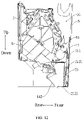
FIG. 13 is a structural diagram of a breezeless member and a driving mechanism according to some embodiments of the present disclosure. -
FIG. 14 is an enlarged view at location C inFIG. 13 . -
FIG. 15 is an exploded view of a breezeless member and a driving mechanism according to some embodiments of the present disclosure. -
FIG. 16 is a structural diagram of a rack according to some embodiments of the present disclosure. -
- air conditioner
indoor unit 100; -
air dispersing hole 10; -
surface frame 1;air inlet 11;first air outlet 12;second air outlet 13;air outlet channel 14;guide portion 141; flowguide portion 142;end plate 15; -
breezeless member 2;first panel 21;non-air output portion 211;decorative hole 2111;air output portion 212; first subair output portion 2121; second subair output portion 2122;air dispersing module 22; mountingplate 221;first vent hole 2212; guidevane assembly 222;stationary blade 2221; movingblade 2222;limit plate 223;second vent hole 2231; -
heat exchanger 3; -
fan 4; -
second panel 5; accommodatingcavity 51; - inner
air guide plate 6; first sub innerair guide plate 61; second sub innerair guide plate 62; -
driving mechanism 7;motor 71;gear 72;rack 73;second guide rail 731; guidegroove 7311;tooth holder 732;tooth portion 7321;non-tooth portion 7322; -
chassis 8;motor mounting base 81;first guide rail 82; guideprotrusion 821; matchingcavity 822; -
louver 9. - The embodiments of the present disclosure are described below in detail, examples of which are illustrated in the accompanying drawings, and the same or similar reference signs refer to the same or similar elements or elements having the same or similar functions throughout. The embodiments described below with reference to the accompanying drawings are exemplary and are only used to explain the present disclosure, but should not be construed as a limitation on the present disclosure.
- An air conditioner
indoor unit 100 according to an embodiment of the present disclosure will be described below with reference to the accompanying drawings. - Referring to
FIGS. 1 to 3 , according to an embodiment of the present disclosure in a first aspect, an air conditionerindoor unit 100 includes asurface frame 1, abreezeless member 2, aheat exchanger 3 and afan 4. Anair inlet 11 is formed on thesurface frame 1, and afirst air outlet 12 is formed in a front lower part of thesurface frame 1. Thefirst air outlet 12 extends forward through a front part of thesurface frame 1 and thefirst air outlet 12 extends downward through a bottom part of thesurface frame 1. Thefirst air outlet 12 can be located in a middle part of a length direction (for example, the length direction is a left and right direction) of thesurface frame 1, and two ends of a length direction of thefirst air outlet 12 can extend to two ends of the length direction of thesurface frame 1. In this way, the air outlet area and the air output volume of thefirst air outlet 11 can be increased, so that the air conditionerindoor unit 100 can discharge air forward through thefirst air outlet 12, and the air conditionerindoor unit 100 can also discharge air downward through thefirst air outlet 12. Asecond air outlet 13 is formed on at least one of a left side of thesurface frame 1 and a right side of thesurface frame 1, so that the air conditionerindoor unit 100 can discharge air from a side through thesecond air outlet 13. Thebreezeless member 2 is disposed on a front side of thesurface frame 1 and movable between a first position and a second position. For example, thebreezeless member 2 is disposed on the front side of thesurface frame 1 and movable up and down between the first position and the second position. Thebreezeless member 2 includes afirst panel 21. Theheat exchanger 3 and thefan 4 are disposed in thesurface frame 1. Theheat exchanger 3 can exchange heat with airflow in thesurface frame 1, and thefan 4 can drive the airflow to flow. - When the
breezeless member 2 is at the first position or the second position, the air is discharged from both thefirst air outlet 12 and thesecond air outlet 13, which can form a 3D or 4D air output, so that more angles of air output and larger range of air output can be realized, the air output volume can be increased and the working efficiency of the air conditionerindoor unit 100 can be improved. For example, thesecond air outlet 13 is formed on the left side of thesurface frame 1, and when the air conditionerindoor unit 100 discharges air, the air can be discharged forward, downward and leftward to form the 3D air output. Thesecond air outlet 13 is formed on the right side of thesurface frame 1, and when the air conditionerindoor unit 100 discharges air, the air can be discharged forward, downward and rightward to form the 3D air output. Thesecond air outlet 13 is formed on each of the left side of thesurface frame 1 and the right side of thesurface frame 1, and when the air conditionerindoor unit 100 discharges air, the air can be discharged forward, downward, leftward and rightward to form the 4D air output. - Optionally, the left side and right side of the
surface frame 1 each is provided with anend plate 15, theend plate 15 can be in a shape of a grid, and thesecond air outlet 13 can discharge air from gaps of theend plate 15, so that when the air conditionerindoor unit 100 is in a breezeless mode, the air can be discharged more softly leftward and rightward, and the overall breezeless effect of the air conditionerindoor unit 100 can be improved. - When the air conditioner
indoor unit 100 is working, thefan 4 drives the airflow from the outside to enter the air conditionerindoor unit 100 through theair inlet 11. The airflow can be discharged from thefirst air outlet 12 after heat exchange with theheat exchanger 3, and the airflow after the heat exchange can also be discharged from thesecond air outlet 13. Thefirst air outlet 12 and thesecond air outlet 13 are provided, thefirst air outlet 12 is located at a front part of thesurface frame 1 and thefirst air outlet 12 penetrates the bottom part of thesurface frame 1, and thesecond air outlet 13 is located at a side of thesurface frame 1, so that the air conditionerindoor unit 100 can discharge air forward, downward and sideward. In this way, the air conditionerindoor unit 100 can discharge air from multiple angles, and at the same time, the air output volume of the air conditionerindoor unit 100 is increased. - When the
breezeless member 2 is located at the first position, thefirst panel 21 opens thefirst air outlet 12, thebreezeless member 2 does not interfere with the discharge of the air from thefirst air outlet 12, and the air conditionerindoor unit 100 has a relatively large air output volume. When thebreezeless member 2 is located at the second position, thefirst panel 21 closes thefirst air outlet 12, and the air conditionerindoor unit 100 can discharge air through thesecond air outlet 13, which can prevent the cold air from directly blowing the human body when the air conditionerindoor unit 100 is in a cooling mode and thus improve user comfort. - In the air conditioner
indoor unit 100 of the present disclosure, when thebreezeless member 2 is located at the second position, thebreezeless member 2 can soften the air discharged from thefirst air outlet 12. Even if thefirst panel 21 blocks the air output from thefirst air outlet 12 and the air output volume of thefirst air outlet 12 is reduced, the air conditionerindoor unit 100 can discharge air through thesecond air outlet 13 at the same time, so that the total air output volume of the air discharged from the air conditionerindoor unit 100 through thefirst air outlet 12 and thesecond air outlet 13 is relatively large. In this way, the air output from the air conditionerindoor unit 100 does not directly blow the human body, and the total air output volume of the air conditionerindoor unit 100 is relatively large, so that the indoor temperature can be quickly adjusted, and the user experience is improved. - In the air conditioner
indoor unit 100 according to the present disclosure, thesurface frame 1 has thefirst air outlet 12 formed in the front part thereof and thefirst air outlet 12 penetrates through the bottom part of thesurface frame 1, and thesurface frame 1 has thesecond air outlet 13 formed in at least one of the left side and the right side thereof, which can achieve multi-angle air output, increase the air output volume and the air output range, achieve rapid cooling and heating, and improve the working efficiency of the air conditionerindoor unit 100. - Referring to
FIGS. 1 to 3 , according to some embodiments of the present disclosure, thebreezeless member 2 is disposed on the front side of thesurface frame 1 and movable up and down between the first position and the second position. This design facilitates the movement of thebreezeless member 2. When thebreezeless member 2 is located at the first position, thefirst panel 21 opens thefirst air outlet 12. When thebreezeless member 2 is located at the second position, thefirst panel 21 closes thefirst air outlet 12. - Referring to
FIGS. 1 to 3 , according to some embodiments of the present disclosure, when thebreezeless member 2 is located at the second position, thefirst panel 21 has an air dispersing structure formed in a part thereof opposite to thefirst air outlet 12. The air dispersing structure may be a plurality of air dispersing holes 10. The airflow can pass through theair dispersing hole 10. Theair dispersing hole 10 has a function of dispersing the airflow, so that the air output from thefirst air outlet 12 is soft and breezeless air output is realized. The air dispersing structure can also be a dispersing grid. The airflow is dispersed when passing through the dispersing grid, which also softens the air output from thefirst air outlet 12 and realizes the breezeless air output. Thebreezeless member 2 with the air dispersing structure is provided, so that it is possible to prevent the cold air from blowing directly to the human body. In this way, the air output is softened, and the breezeless air output mode can be realized, and the air conditionerindoor unit 100 can have a relatively large cooling capacity in the breezeless mode. - In the description of the present disclosure, "plurality" means two or more.
- Referring to
FIGS. 4 to 6 , according to some embodiments of the present disclosure, thesurface frame 1 has asecond panel 5 provided at an upper end thereof and thesecond panel 5 is located on the front side of thesurface frame 1. Anaccommodating cavity 51 is defined between thesecond panel 5 and thesurface frame 1, and a bottom part of theaccommodating cavity 51 can be open. When thebreezeless member 2 is located at the second position, at least a part of thefirst panel 21 is located in theaccommodating cavity 51. For example, when thebreezeless member 2 is located at the second position, a part of thefirst panel 21 is located in theaccommodating cavity 51; or when thebreezeless member 2 is located at the second position, the entirefirst panel 21 is located in theaccommodating cavity 51. This design allows thesecond panel 5 to protect thefirst panel 21. At the same time, thesecond panel 5 can limit and guide the movement of thefirst panel 21, which facilitates the movement of thebreezeless member 2 in a predetermined direction between the first position and the second position. - Referring to
FIGS. 6 and8 , optionally, thefirst panel 21 includes anair output portion 212 having an air dispersing structure thereon. When thebreezeless member 2 is located at the second position, theair output portion 212 and thefirst air outlet 12 are opposite to each other, so that the air output from thefirst air outlet 12 can be dispersed by the air dispersing structure, thereby realizing the breezeless air output from thefirst air outlet 12. - Referring to
FIGS. 6 and8 , further, thefirst panel 21 includes anon-air output portion 211 and theair output portion 212 that are connected to each other up and down. Theair output portion 212 has a plurality of air dispersing structures formed thereon, and the airflow can be dispersed when passing through the air dispersing structure to reduce the breeziness of the airflow. Thenon-air output portion 211 is located above theair output portion 212. When thebreezeless member 2 is located at the second position, theair output portion 212 is opposite to thefirst air outlet 12, so that the air output from thefirst air outlet 12 can be dispersed by the air dispersing structure, thereby realizing the breezeless air output from thefirst air outlet 12. Thenon-air output portion 211 is located in theaccommodating cavity 51, which can prevent thefirst panel 21 from falling off from theaccommodating cavity 51. - Optionally, when the air dispersing structure is a plurality of air dispersing holes 10, the
non-air output portion 211 has a plurality ofdecorative holes 2111 formed therein and having the same appearance as the air dispersing holes 10. This design makes theair output portion 212 and thenon-air output portion 211 have the same appearance and is more aesthetic. - Referring to
FIGS. 4 to 8 , further, thebreezeless member 2 includes anair dispersing module 22 having an air dispersing function. Theair dispersing module 22 is disposed on theair output portion 212 and is located at an inner side of theair output portion 212, and theair output portion 212 can protect theair dispersing module 22. - Further, the
air dispersing module 22 includes a mountingplate 221. The mountingplate 221 has a plurality of first vent holes 2212 formed therein and arranged in a left and right direction. The mountingplate 221 is connected to thefirst panel 21, and the airflow can pass through thefirst vent hole 2212, so as to ensure that when thebreezeless member 2 is located at the second position, the air output from the air conditionerindoor unit 100 can flow through thefirst vent hole 2212 and be smoothly discharged from thefirst air outlet 12. - Further, the
air dispersing module 22 includes an air dispersing mechanism with an air dispersing function. The air dispersing mechanism is disposed at thefirst vent hole 2212. The air dispersing mechanism can further disperse the airflow flowing through thefirst vent hole 2212, so that the airflow is softer. - Further, the air dispersing mechanism includes a
guide vane assembly 222. Eachfirst vent hole 2212 is provided with aguide vane assembly 222. Theguide vane assembly 222 includes astationary blade 2221 and a rotatable movingblade 2222. Thestationary blade 2221 and the movingblade 2222 are arranged along an axial direction of thefirst vent hole 2212. When the airflow passes through thefirst vent hole 2212, the relative position of blades of the movingblade 2222 and blades of thestationary blade 2221 can be adjusted by controlling the rotation of the movingblade 2222. In this way, the vent area of thefirst vent hole 2212 can be adjusted, and the air output volume and air output speed can be adjusted. When the air conditionerindoor unit 100 is working and thebreezeless member 2 is located at the second position, the movingblade 2222 can be controlled to rotate to a certain angle and then stop rotating, or the movingblade 2222 can be controlled to rotate all the time. - Referring to
FIGS. 9 to 15 , optionally, the movingblade 2222 is disposed on a front side or a rear side of thestationary blade 2221. When the movingblade 2222 is disposed on the front side of thestationary blade 2221, the airflow first passes through the motionlessstationary blade 2221, and then passes through therotatable moving blade 2222. The airflow is subject to the guiding, rectifying and dispersing effects of thestationary blade 2221 in turn, and then flows through the movingblade 2222. The movingblade 2222 can rotate in a certain direction, so that the airflow has a certain rotating component after passing through the movingblade 2222. Finally, the airflow passes through the air dispersing structure on theair output portion 212 and is further dispersed, so that the air output is softer and more resembles the natural wind. - When the moving
blade 2222 is disposed on the rear side of thestationary blade 2221, the airflow passes through the movingblade 2222 and thestationary blade 2221 in turn when flowing through theair dispersing module 22. The movingblade 2222 can have a certain rotation direction, so that the airflow has a certain rotational component after flowing through the movingblade 2222. Then the airflow is guided, rectified and dispersed by thestationary blades 2221, and finally the airflow is further dispersed through the air dispersing structure on theair output portion 212, making the air output softer and more resemble the natural wind. - Referring to
FIGS. 9 to 15 , optionally, the movingblade 2222 and thestationary blade 2221 are disposed coaxially. This design makes it easy to adjust the vent area of thefirst vent hole 2212 by rotating the movingblade 2222, and at the same time facilitates disposing of the movingblade 2222 and thestationary blade 2221. - Referring to
FIGS. 9 to 15 , according to some optional embodiments of the present disclosure, theair dispersing module 22 includes alimit plate 223. Thelimit plate 223 is connected to thefirst panel 21, and thelimit plate 223 is disposed on a front side of the mountingplate 221 and connected to the mountingplate 221. The limitingplate 223 has second vent holes 2231 formed therein and opposite to and in communication with thefirst vent holes 2212, so that the air output flowing through thefirst vent holes 2212 can be discharged from the second vent holes 2231, and thelimit plate 223 is prevented from blocking the airflow. An accommodating cavity adapted to accommodate the air dispersing mechanism is defined between the mountingplate 221 and thelimit plate 223. The mountingplate 221 and thelimit plate 223 can protect the air dispersing mechanism. The air output from thefirst air outlet 12 can enter the accommodating cavity through thefirst vent hole 2212, the air dispersing mechanism in the accommodating cavity can change the flowing direction of the airflow, and then the air is discharged from thesecond vent hole 2231. - Referring to
FIGS. 4 to 8 , according to some embodiments of the present disclosure, theair output portion 212 includes a first subair output portion 2121 and a second subair output portion 2122 that are connected to each other up and down. Each of the first subair output portion 2121 and the second subair output portion 2121 has the air dispersing structure formed thereon, so that the airflow can be dispersed by the air dispersing structure when passing through the first subair output portion 2121, and the airflow can be dispersed by the air dispersing structure when passing through the second subair output portion 2122, thereby making the airflow softer. An included angle is defined between the first subair output portion 2121 and the second subair output portion 2122. Theair dispersing module 22 is disposed on the first subair output portion 2121, and theair dispersing module 22 can soften the airflow flowing through the first subair output portion 2121 and adjust the flowing direction of the airflow. When thebreezeless member 2 is located at the second position, the first subair output portion 2121 is located at a front side of thefirst air outlet 12, and the second subair output portion 2122 is located at a bottom part of thefirst air outlet 12. This design enables, when the airflow in the air conditionerindoor unit 100 is discharged through thefirst air outlet 12, the airflow passing through the first subair output portion 2121 to be output forward and the airflow passing through the second subair output portion 2122 to be discharged generally downward, which is beneficial to realizing the multi-angle air output of the air conditionerindoor unit 100. - Referring to
FIGS. 4 to 6 , according to some optional embodiments of the present disclosure, theair output portion 212 includes a first subair output portion 2121 and a second subair output portion 2122 that are connected to each other up and down. Each of the first subair output portion 2121 and the second subair output portion 2122 has the air dispersing structure formed thereon, so that the airflow can be dispersed by the air dispersing structure when passing through the first subair output portion 2121, and the airflow can be dispersed by the air dispersing structure when passing through the second subair output portion 2122, thereby making the airflow softer. There is an included angle between the firstsub air outlet 2121 portion and the secondsub air outlet 2122 portion. When thebreezeless member 2 is at the second position, the firstsub air outlet 2121 portion is located at the front side of thefirst air outlet 12, and the secondsub air outlet 2122 portion is located at the bottom of thefirst air outlet 12. This design enables, when the airflow in the air conditionerindoor unit 100 is discharged through thefirst air outlet 12, the airflow passing through the first subair output portion 2121 to be output forward and the airflow passing through the second subair output portion 2122 to be discharged generally downward, which is beneficial to realizing the multi-angle air output of the air conditionerindoor unit 100. - Referring to
FIGS. 4 to 6 , further, the included angle between the first subair output portion 2121 and the second subair output portion 2122 ranges from 60° to 120°. If the included angle between the first subair output portion 2121 and the second subair output portion 2122 is too large, the structure of the air conditionerindoor unit 100 will not be compact, and the appearance of the whole unit will be less aesthetic. If the included angle between the first subair output portion 2121 and the second subair output portion 2122 is too small, it is easy to cause unsmooth flowing when the airflow passing through the second subair output portion 2122 and relatively large noise because of the unsmooth flowing of the airflow. By limiting the included angle between the first subair output portion 2121 and the second subair output portion 2122 within an appropriate range, the air conditionerindoor unit 100 can be compact while it is ensured that the airflow can smoothly pass through the second subair output portion 2122 and be discharged downward. - Referring to
FIGS. 4 to 6 , according to some embodiments of the present disclosure, thesurface frame 1 has anair outlet channel 14 in communication with thefirst air outlet 12 and thesecond air outlet 13. The airflow in theair outlet channel 14 can be discharged through thefirst air outlet 12. The airflow in theair outlet channel 14 can also be discharged through thesecond air outlet 13. Aguide portion 141 is formed on a part of a bottom wall of theair outlet channel 14 adjacent to thefirst air outlet 12. Theguide portion 141 is used to guide the airflow toward thefirst air outlet 12. Theguide portion 141 may direct a part of the airflow downward. Theguide portion 141 also may direct a part of the airflow forward. - Referring to
FIGS. 4 to 6 , further, in a rear-to-front direction, theguide portion 141 extends obliquely and downward to guide a part of the airflow to a bottom part of thefirst air outlet 12. This design enables theguide portion 141 to guide the airflow to be discharged from the bottom part of the air conditionerindoor unit 100, which is beneficial to increasing the air output volume from the bottom part of the air conditionerindoor unit 100, and realizing the multi-angle air output of the air conditionerindoor unit 100. - Optionally, the
air outlet channel 14 has alouver 9 provided therein, and thelouver 9 can adjust the flowing direction of the airflow in the air outlet channel. - Referring to
FIGS. 4 to 8 , according to some optional embodiments of the present disclosure, an included angle between theguide portion 141 and a vertical direction ranges from 15° to 60°. If the included angle between theguide portion 141 and the vertical direction is too small, then when the airflow in theair outlet channel 14 flows to theguide portion 141 along a bottom wall of theair outlet channel 14, the flowing direction of the airflow changes greatly, and the guiding effect of theguide portion 141 on the airflow is reduced. If the included angle between theguide portion 141 and the vertical direction is too large, it is unfavorable for theguide portion 141 to guide the airflow to the bottom part of thefirst air outlet 12, and the air output volume from the bottom part of the air conditionerindoor unit 100 decreases. By limiting the included angle between theguide portion 141 and the vertical direction within an appropriate range, it is convenient for theguide portion 141 to guide a part of the airflow in theair outlet channel 14 to be discharged from the bottom part of thefirst air outlet 12. - Referring to
FIGS. 4 to 6 , according to some optional embodiments of the present disclosure, the bottom wall of theair outlet channel 14 has a part thereof on a side of theguide portion 141 away from thefirst air outlet 12 as aflow guide portion 142, and the included angle between theguide portion 141 and the vertical direction is smaller than an included angle between theflow guide portion 142 and the vertical direction. This design enables theflow guide portion 142 to effectively guide the airflow in theair outlet channel 14 to flow. When the airflow flows from theflow guide portion 142 to theguide portion 141, the flowing direction of the airflow changes abruptly, and theguide portion 141 can effectively guide a part of the airflow to be discharged from the bottom part of thefirst air outlet 12. - Referring to
FIG. 6 , optionally, when thebreezeless member 2 is located at the second position, theguide portion 141 is opposite to or abuts against a bottom part of thefirst panel 21 in a front and rear direction. This design can prevent the airflow in theair outlet channel 14 from leaking from the gap between theguide portion 141 and the bottom part of thefirst panel 21, and avoid problems, such as noise and condensation due to air leakage. - Referring to
FIGS. 4 to 6 , according to some embodiments of the present disclosure, thesurface frame 1 has anair outlet channel 14 therein that is in communication with both thefirst air outlet 12 and thesecond air outlet 13, and theair outlet channel 14 has a rotatable innerair guide plate 6 provided therein. The innerair guide plate 6 is disposed in theair outlet channel 14, so that change and adjustment of the air outlet direction can be realized by the rotation of the innerair guide plate 6. - Referring to
FIGS. 4 to 6 , optionally, the air conditionerindoor unit 100 has a heating mode and a cooling mode. When thebreezeless member 2 is located at the first position and the air conditionerindoor unit 100 is in the cooling mode, an included angle between the innerair guide plate 6 and a horizontal plane ranges from 0 to 45°, so that the innerair guide plate 6 can guide the airflow in theair outlet channel 14 to flow forward from thefirst air outlet 12. In this way, the cold air can reach a higher position in the room, which is conducive to the uniform cooling of the room. When thebreezeless member 2 is located at the first position and the air conditionerindoor unit 100 is in the heating mode, the included angle between the innerair guide plate 6 and the horizontal plane ranges from 45° to 90°, so that the innerair guide plate 6 can guide the airflow in theair outlet channel 14 to flow downward from thefirst air outlet 12. In this way, the warm air can reach a lower position in the room, which is beneficial to the uniform heating of the room. - Referring to
FIGS. 4 to 6 , optionally, a length of the innerair guide plate 6 in an air outlet direction of thefirst air outlet 12 is adjustable. This design can adjust the guiding effect of the innerair guide plate 6 on the airflow. When the innerair guide plate 6 is long, the guiding effect of the innerair guide plate 6 on the airflow is strong. Referring toFIGS. 4 to 6 , according to some optional embodiments of the present disclosure, when thebreezeless member 2 is located at the first position, the length of the innerair guide plate 6 in the air outlet direction of thefirst air outlet 12 is L1. When thebreezeless member 2 is located at the second position, the length of the innerair guide plate 6 in the air outlet direction of thefirst air outlet 12 is L2, and L2 is smaller than L1. This design enables the innerair guide plate 6 to have a strong guiding effect on the airflow when thebreezeless member 2 is located at the first position, which is beneficial to increasing the air output volume of thefirst air outlet 12; and when thebreezeless member 2 is located at the second position, by reducing the length of the innerair guide plate 6 in the air outlet direction of thefirst air outlet 12, the innerair guide plate 6 can be prevented from interfering with thebreezeless member 2. - Referring to
FIGS. 7 and8 , according to some optional embodiments of the present disclosure, the innerair guide plate 6 includes a first sub innerair guide plate 61 and a second sub innerair guide plate 62. The first sub innerair guide plate 61 is rotatably connected to an inner wall of theair outlet channel 14, and this design facilitates the adjustment of the included angle between the innerair guide plate 6 and the horizontal plane. The second sub innerair guide plate 62 is slidably disposed on the first sub innerair guide plate 61 to adjust the length of the innerair guide plate 6 in the air outlet direction of thefirst air outlet 12. This design facilitates the adjustment of the length of the innerair guide plate 6 in the air outlet direction of thefirst air outlet 12, and the structure is simple. For example, the adjustment of the length of the innerair guide plate 6 in the air outlet direction of thefirst air outlet 12 can be realized by the movement of the second sub air guide plate relative to the first sub air guide plate. - Referring to
FIG. 7 andFIG. 8 , further, the second sub innerair guide plate 62 is slidable or rotatable relative to the first sub innerair guide plate 61. When the second sub innerair guide plate 62 is slidable relative to the first sub innerair guide plate 61, the second sub innerair guide plate 62 can be slid onto the first sub innerair guide plate 61 to make the second sub innerair guide plate 62 overlap the first sub innerair guide plate 61, thereby reducing the length of the innerair guide plate 6 in the air outlet direction of thefirst air outlet 12. It is also possible to slide the second sub innerair guide plate 62 to make the second sub innerair guide plate 62 become an extension of the first sub innerair guide plate 61, thereby increasing the length of the innerair guide plate 6 in the air outlet direction of thefirst air outlet 12. When the second sub innerair guide plate 62 is rotatable relative to the first sub innerair guide plate 61, the second sub innerair guide plate 62 can be rotated to make the second sub innerair guide plate 62 overlap the first sub innerair guide plate 61, thereby reducing the length of the innerair guide plate 6 in the air outlet direction of thefirst air outlet 12. It is also possible to rotate the second sub innerair guide plate 62 to make the second sub innerair guide plate 62 become an extension of the first sub innerair guide plate 61, thereby further increasing the length of the innerair guide plate 6 in the air outlet direction of thefirst air outlet 12. - Referring to
FIG. 7 andFIG. 8 , further, a sliding cavity is defined in the first sub innerair guide plate 61, and the second sub innerair guide plate 62 is slidably disposed in the sliding cavity. This design makes the sliding process of the second sub innerair guide plate 6 more reliable, and the disengagement of the second sub innerair guide plate 62 and the first sub innerair guide plate 61 is avoided. - Referring to
FIGS. 6 and8 , according to some embodiments of the present disclosure, thesurface frame 1 has anair outlet channel 14 therein that is in communication with both thefirst air outlet 12 and thesecond air outlet 13. When thebreezeless member 2 is located at the first position, the bottom part of thefirst panel 21 is adapted to abut against a top wall of theair outlet channel 14. This design prevents the airflow in theair outlet channel 14 from breaking into the gap between the top wall of theair outlet channel 14 and thefirst panel 21 when thebreezeless member 2 is located at the second position, thereby preventing loss of air volume. - Referring to
FIGS. 9 to 15 , according to some embodiments of the present disclosure, adriving mechanism 7 for driving thebreezeless member 2 to move includes amotor 71, agear 72 and arack 73. For example, thedriving mechanism 7 is used to drive thebreezeless member 2 to move up and down, when thebreezeless member 2 is disposed on the front side of thesurface frame 1 and movable up and down between the first position and the second position. Themotor 71 is disposed on achassis 8 or thesurface frame 1 of the air conditionerindoor unit 100. Thegear 72 is connected to an output shaft of themotor 71, and themotor 71 can drive thegear 72 to rotate when themotor 71 works. Therack 73 is disposed on thebreezeless member 2 and extends in the up and down direction. Therack 73 is adapted to engage with thegear 72. Through the cooperation between therack 73 and thegear 72, when themotor 71 is working, therack 73 can be driven to move, and thebreezeless member 2 can be driven to move. - Referring to
FIGS. 9 to 15 , optionally, therack 73 is disposed on thefirst panel 21, and therack 73 is detachably connected to thefirst panel 21 or therack 73 is integrally formed with thefirst panel 21. When therack 73 is detachably connected to thefirst panel 21, thedriving mechanism 7 and thebreezeless member 2 are easily assembled. For example, therack 73 is connected to thefirst panel 21 in a clamping manner; or therack 73 and thefirst panel 21 are connected in a screwing manner. When therack 73 and thefirst panel 21 are integrally formed, therack 73 and thefirst panel 21 have high connection strength, which can improve the reliability of the air conditionerindoor unit 100. - In some embodiments of the present disclosure, the
breezeless member 2 includes an air dispersing module, therack 73 is disposed on the air dispersing module, and therack 73 is detachably connected to the air dispersing module, so that thedriving mechanism 7 and thebreezeless member 2 are easily assembled. For example, therack 73 is connected to the air dispersing module in a clamping manner; or therack 73 and the air dispersing module are connected in a screwing manner. - Referring to
FIGS. 9 to 15 , optionally, one of thechassis 8 and thebreezeless member 2 has afirst guide rail 82 provided thereon, and the other of thechassis 8 and thebreezeless member 2 has asecond guide rail 731 provided thereon. Thesecond guide rail 731 is matched with thefirst guide rail 82. For example, thechassis 8 has afirst guide rail 82 provided thereon, and thebreezeless member 2 has asecond guide rail 731 provided thereon that is matched with thefirst guide rail 82. Or, thebreezeless member 2 has afirst guide rail 82 provided thereon, and thechassis 8 has asecond guide rail 731 provided thereon that is matched with thefirst guide rail 82. Through the cooperation of thefirst guide rail 82 and thesecond guide rail 731, the movement of thebreezeless member 2 between the first position and the second position can be realized. Thefirst guide rail 82 and thesecond guide rail 731 can mutually guide each other, which makes the movement of thebreezeless member 2 more reliable. - Alternatively, one of the
surface frame 1 and thebreezeless member 2 has afirst guide rail 82 provided thereon, and the other of thesurface frame 1 and thebreezeless member 2 has asecond guide rail 731 provided thereon. Thesecond guide rail 731 is matched with thefirst guide rail 82. For example, thesurface frame 1 has afirst guide rail 82 provided thereon, and thebreezeless member 2 has asecond guide rail 731 provided thereon that is matched with thefirst guide rail 82. Or, thebreezeless member 2 has afirst guide rail 82 provided thereon, and thesurface frame 1 has asecond guide rail 731 provided thereon that is matched with thefirst guide rail 82. Through the cooperation of thefirst guide rail 82 and thesecond guide rail 731, the movement of thebreezeless member 2 between the first position and the second position can be realized. Thefirst guide rail 82 and thesecond guide rail 731 can mutually guide each other, which makes the movement of thebreezeless member 2 more reliable. - Referring to
FIGS. 9 to 15 , further, thechassis 8 or thesurface frame 1 has amotor mounting base 81 provided thereon, and themotor 71 is disposed on themotor mounting base 81, so that themotor 71 is stably mounted on thechassis 8. Thefirst guide rail 82 is disposed on themotor mounting base 81, and thesecond guide rail 731 is disposed on therack 73. This design makes thefirst guide rail 82 and thesecond guide rail 731 easy to form, makes the structure simple, and makes it convenient for thefirst guide rail 82 and thesecond guide rail 731 to cooperate. - Referring to
FIGS. 9 to 15 , further, themotor mounting base 81 has amatching cavity 822 formed therein and having a front side that is open. At least a part of thegear 72 is located in thematching cavity 822. For example, a part of thegear 72 is located in thematching cavity 822; or theentire gear 72 is located in thematching cavity 822. A part of therack 73 extends into thematching cavity 822 and engages with thegear 72. This design enables thematching cavity 822 to protect thegear 72. Thesecond guide rail 731 includesguide grooves 7311 formed on a left side wall and a right side wall of therack 73. Thefirst guide rail 82 includesguide protrusions 821 formed on a left side wall and a right side wall of an open end of thematching cavity 822. Eachguide protrusion 821 fits in acorresponding guide groove 7311 and is slidable up and down relative to theguide groove 7311. This design makes it difficult for thefirst guide rail 82 and thesecond guide rail 731 to disengage, and theguide protrusion 821 moves within theguide groove 7311 smoothly. - Referring to
FIG. 16 , according to some optional embodiments of the present disclosure, therack 73 includes atooth holder 732. Thetooth holder 732 has atooth portion 7321 and anon-tooth portion 7322 on a surface thereof facing towards thegear 72 . Thetooth portion 7321 extends in an up and down direction, and thetooth portion 7321 is adapted to engage with thegear 72. Thenon-tooth portion 7322 is located on at least one side of a length direction of thetooth portion 7321, and thenon-tooth portion 7322 cannot engage with thegear 72. For example, thenon-tooth portion 7322 is located above thetooth portion 7321. When thebreezeless member 2 moves downward, thetooth portion 7321 engages with thegear 72, so that therack 73 moves downward relative to thegear 72. With the downward movement of therack 73, when thegear 72 contacts thenon-tooth portion 7322, thenon-tooth portion 7322 cannot engage with thegear 72, so that therack 73 can be prevented from moving downward excessively. Or, thenon-tooth portion 7322 is located under thetooth portion 7321. When thebreezeless member 2 moves upward, thetooth portion 7321 engages with thegear 72, so that therack 73 moves upward relative to thegear 72. With the upward movement of therack 73, when thegear 72 contacts thenon-tooth portion 7322, thenon-tooth portion 7322 cannot engage with thegear 72, so that therack 73 can be prevented from moving upward excessively. Or, thenon-tooth portion 7322 is located on both sides of the length direction of thetooth portion 7321, and in this case, thenon-tooth portion 7322 provided can prevent therack 73 from moving upward and downward excessively. Thenon-tooth portion 7322 is provided, which can prevent therack 73 from moving too much and disengaging from thegear 72, thereby improving the reliability of thedriving mechanism 7. - The air conditioner according to the embodiments of the present disclosure in the second aspect includes the air conditioner
indoor unit 100 according to the embodiments of the present disclosure in the first aspect. For example, the air conditioner is a split floor-standing air conditioner, and the air conditionerindoor unit 100 is a split floor-standing air conditionerindoor unit 100; or the air conditioner is a split wall-mounted air conditioner, and the air conditionerindoor unit 100 is a split wall-mounted air conditionerindoor unit 100. - According to the air conditioner of the present disclosure, the above air conditioner
indoor unit 100 is provided, the air conditionerindoor unit 100 can discharge air from multiple angles and the air output volume is large, so that the air conditioner can discharge air from multiple angles, the air output volume and the air output range of the air conditioner can be improved, and the working efficiency of the air conditioner is improved. - In the description of this specification, the appearance of reference terms "an embodiment," "some embodiments," "exemplary embodiment," "example," "specific example," or "some examples", etc., is meant to incorporate particular features, structures, materials, or characteristics described in combination with the embodiments or the examples into at least one embodiment or example of the present disclosure. In this specification, schematic representations of the above terms do not necessarily refer to the same embodiment or example. Furthermore, the particular features, structures, materials or characteristics described may be combined in any suitable manner in any one or more embodiments or examples.
- Although the embodiments of the present disclosure have been shown and described, it will be understood by those of ordinary skill in the art that various changes, modifications, substitutions and variants can be made to these embodiments without departing from the principles and spirit of the present disclosure. The scope of the disclosure is defined by the claims and their equivalents.
Claims (36)
- An air conditioner indoor unit, comprising: a surface frame having an air inlet, a first air outlet formed in a front lower part of the surface frame, and a second air outlet formed on at least one of a left side and a right side of the surface frame, wherein the first air outlet extends forward through a front part of the surface frame and the first air outlet extends downward through a bottom part of the surface frame; a breezeless member disposed on a front side of the surface frame and movable between a first position and a second position, the breezeless member comprising a first panel; and a heat exchanger and a fan, disposed in the surface frame, wherein: the first panel is configured to open the first air outlet when the breezeless member is at the first position, and the first panel is configured to close the first air outlet when the breezeless member is at the second position.
- The air conditioner indoor unit according to claim 1, wherein the breezeless member is disposed on the front side of the surface frame and movable up and down between the first position and the second position.
- The air conditioner indoor unit according to claim 1 or 2, wherein when the breezeless member is at the second position, the first panel has an air dispersing structure formed in a part thereof opposite to the first air outlet.
- The air conditioner indoor unit according to any one of claims 1 to 3, wherein the surface frame has a second panel provided on an upper end of the surface frame, the second panel being located on the front side of the surface frame, an accommodating cavity is defined between the second panel and the surface frame, and when the breezeless member is at the second position, at least a part of the first panel is located in the accommodating cavity.
- The air conditioner indoor unit according to claim 4, wherein the first panel comprises an air output portion having an air dispersing structure, and when the breezeless member is at the second position, the air output portion is opposite to the first air outlet.
- The air conditioner indoor unit according to claim 4, wherein: the first panel comprises a non-air output portion and an air output portion that are connected to each other up and down, the air output portion has an air dispersing structure, and the non-air output portion is located above the air output portion; and when the breezeless member is at the second position, the air output portion is opposite to the first air outlet, and the non-air output portion is located in the accommodating cavity.
- The air conditioner indoor unit according to claim 5 or 6, wherein: the breezeless member comprises an air dispersing module having an air dispersing function, and the air dispersing module is disposed on the air output portion and located at an inner side of the air output portion.
- The air conditioner indoor unit according to claim 7, wherein the air dispersing module comprises: a mounting plate having a plurality of first vent holes, the plurality of first vent holes being arranged in a left and right direction, wherein the mounting plate is connected to the first panel.
- The air conditioner indoor unit according to claim 8, wherein the air dispersing module comprises an air dispersing mechanism with an air dispersing function, the air dispersing mechanism being disposed at the plurality of first vent holes.
- The air conditioner indoor unit according to claim 9, wherein the air dispersing mechanism comprises a guide vane assembly disposed in each of the plurality of first vent holes, the guide vane assembly comprising a stationary blade and a rotatable moving blade that are arranged along an axial direction of the first vent hole.
- The air conditioner indoor unit according to claim 10, wherein the moving blade is disposed on a front side or a rear side of the stationary blade.
- The air conditioner indoor unit according to claim 10, wherein the moving blade and the stationary blade are disposed coaxially.
- The air conditioner indoor unit according to claim 9, wherein: the air dispersing module comprises a limit plate connected to the first panel, and the limit plate is disposed on a front side of the mounting plate and is connected to the mounting plate, the limit plate has second vent holes, the second vent holes being opposite to and in communication with the plurality of first vent holes, and an accommodating cavity is defined between the mounting plate and the limit plate and adapted to accommodate the air dispersing mechanism.
- The air conditioner indoor unit according to claim 5 or 6, wherein the air output portion comprises a first sub air output portion and a second sub air output portion that are connected to each other up and down, and each of the first sub air output portion and the second sub air output portion has the air dispersing structure, an included angle is defined between the first sub air output portion and the second sub air output portion, an air dispersing module is disposed on the first sub air output portion, and when the breezeless member is at the second position, the first sub air output portion is located on a front side of the first air outlet, and the second sub air output portion is located at a bottom part of the first air outlet.
- The air conditioner indoor unit according to claim 5 or 6, wherein the air output portion comprises a first sub air output portion and a second sub air output portion that are connected to each other up and down, and each of the first sub air output portion and the second sub air output portion has the air dispersing structure formed thereon, an included angle is defined between the first sub air output portion and the second sub air output portion, and when the breezeless member is at the second position, the first sub air output portion is located on a front side of the first air outlet, and the second sub air output portion is located at a bottom part of the first air outlet.
- The air conditioner indoor unit according to claim 15, wherein the included angle between the first sub air output portion and the second sub air output portion ranges from 60° to 120°.
- The air conditioner indoor unit according to any one of claims 1-16, wherein the surface frame has an air outlet channel in communication with both the first air outlet and the second air outlet, and a guide portion is formed on a part of a bottom wall of the air outlet channel adjacent to the first air outlet, the guide portion being used to guide airflow towards the first air outlet.
- The air conditioner indoor unit of claim 17, wherein in a rear-to-front direction, the guide portion extends obliquely and downward to guide a part of the airflow to a bottom part of the first air outlet.
- The air conditioner indoor unit according to claim 17, wherein an included angle between the guide portion and a vertical direction ranges from 15° to 60°.
- The air conditioner indoor unit according to claim 19, wherein the bottom wall of the air outlet channel has a part thereof on a side of the guide portion away from the first air outlet as a flow guide portion, and the included angle between the guide portion and the vertical direction is smaller than an included angle between the flow guide portion and the vertical direction.
- The air conditioner indoor unit according to claim 17, wherein when the breezeless member is at the second position, the guide portion is opposite to or abuts against a bottom part of the first panel in a front and rear direction.
- The air conditioner indoor unit according to any one of claims 1 to 16, wherein:
the surface frame has an air outlet channel in communication with both the first air outlet and the second air outlet, and a rotatable inner air guide plate is provided in the air outlet channel. - The air conditioner indoor unit according to claim 22, wherein: the air conditioner indoor unit has a heating mode and a cooling mode; when the breezeless member is at the first position and the air conditioner indoor unit is in the cooling mode, an included angle between the inner air guide plate and a horizontal plane ranges from 0 to 45°; and when the breezeless member is at the first position and the air conditioner indoor unit is in the heating mode, the included angle between the inner air guide plate and the horizontal plane ranges from 45° to 90°.
- The air conditioner indoor unit according to claim 22, wherein a length of the inner air guide plate in an air outlet direction of the first air outlet is adjustable.
- The air conditioner indoor unit according to claim 24, wherein when the breezeless member is at the first position, the length of the inner air guide plate in the air outlet direction of the first air outlet is L1, and when the breezeless member is at the second position, the length of the inner air guide plate in the air outlet direction of the first air outlet is L2, wherein L2 is smaller than L1.
- The air conditioner indoor unit according to claim 24, wherein the inner air guide plate comprises: a first sub inner air guide plate rotatably connected to an inner wall of the air outlet channel; and a second sub inner air guide plate slidably disposed on the first sub inner air guide plate and configured to adjust the length of the inner air guide plate in the air outlet direction of the first air outlet.
- The air conditioner indoor unit according to claim 26, wherein the second sub inner air guide plate is slidable or rotatable relative to the first sub inner air guide plate.
- The air conditioner indoor unit according to claim 27, wherein the first sub inner air guide plate has a sliding cavity, the second sub inner air guide plate being slidably disposed in the sliding cavity.
- The air conditioner indoor unit according to any one of claims 1 to 16, wherein the surface frame has an air outlet channel in communication with both the first air outlet and the second air outlet, and when the breezeless member is at the first position, a bottom part of the first panel is configured to abut against a top wall of the air outlet channel.
- The air conditioner indoor unit according to any one of claims 1 to 29, further comprising a driving mechanism for driving the breezeless member to move, wherein the driving mechanism comprises: a motor disposed on a chassis or the surface frame of the air conditioner indoor unit; a gear connected to an output shaft of the motor; and a rack disposed on the breezeless member and extending in an up and down direction, the rack being configured to engage with the gear.
- The air conditioner indoor unit according to claim 30, wherein: the rack is disposed on the first panel, and the rack is detachably connected to the first panel, or the rack is integrally formed with the first panel.
- The air conditioner indoor unit according to claim 30, wherein: a first guide rail is disposed on one of the chassis and the breezeless member, and a second guide rail is disposed on the other of the chassis and the breezeless member and is matched with the first guide rail; or the first guide rail is disposed on one of the surface frame and the breezeless member, and the second guide rail is disposed on the other of the surface frame and the breezeless member and is matched with the first guide rail.
- The air conditioner indoor unit according to claim 32, wherein: a motor mounting base is disposed on the chassis, the motor is disposed on the motor mounting base, the first guide rail is disposed on the motor mounting base, and the second guide rail is disposed on the rack.
- The air conditioner indoor unit according to claim 33, wherein: the motor mounting base has a matching cavity, the matching cavity having a front side that is open, at least a part of the gear is located in the matching cavity, and a part of the rack extends into the matching cavity and engages with the gear, the second guide rail comprises guide grooves formed on a left side wall and a right side wall of the rack, the first guide rail comprises guide protrusions formed on a left side wall and a right side wall of an open end of the matching cavity, and each of the guide protrusions fits in a corresponding one of the guide grooves and is slidable up and down relative to the corresponding guide groove.
- The air conditioner indoor unit according to claim 30, wherein: the rack comprises a tooth holder, the tooth holder having a tooth portion and a non-tooth portion on a surface thereof facing towards the gear, the tooth portion extends in an up and down direction and is adapted to engage with the gear, and the non-tooth portion is located on at least one side of a length direction of the tooth portion.
- An air conditioner, comprising the air conditioner indoor unit according to any one of claims 1 to 35.
Applications Claiming Priority (3)
| Application Number | Priority Date | Filing Date | Title |
|---|---|---|---|
| CN201921961260.XU CN211119679U (en) | 2019-11-13 | 2019-11-13 | Air conditioner indoor unit and air conditioner |
| CN201911108246.XA CN110701683A (en) | 2019-11-13 | 2019-11-13 | Air conditioner indoor unit and air conditioner |
| PCT/CN2020/127805 WO2021093728A1 (en) | 2019-11-13 | 2020-11-10 | Air conditioner indoor unit and air conditioner |
Publications (4)
| Publication Number | Publication Date |
|---|---|
| EP4056908A1 true EP4056908A1 (en) | 2022-09-14 |
| EP4056908A4 EP4056908A4 (en) | 2022-12-21 |
| EP4056908B1 EP4056908B1 (en) | 2024-03-06 |
| EP4056908C0 EP4056908C0 (en) | 2024-03-06 |
Family
ID=75911791
Family Applications (1)
| Application Number | Title | Priority Date | Filing Date |
|---|---|---|---|
| EP20887280.4A Active EP4056908B1 (en) | 2019-11-13 | 2020-11-10 | Air conditioner indoor unit |
Country Status (3)
| Country | Link |
|---|---|
| US (1) | US20220268481A1 (en) |
| EP (1) | EP4056908B1 (en) |
| WO (1) | WO2021093728A1 (en) |
Families Citing this family (2)
| Publication number | Priority date | Publication date | Assignee | Title |
|---|---|---|---|---|
| CN214415871U (en) * | 2020-12-09 | 2021-10-19 | 深圳市安拓浦科技有限公司 | Wall-mounted air purifier |
| CN114046562A (en) * | 2021-11-17 | 2022-02-15 | 江苏友奥电器有限公司 | Non-wind-sensing mechanism and air conditioner with built-in mechanism |
Family Cites Families (18)
| Publication number | Priority date | Publication date | Assignee | Title |
|---|---|---|---|---|
| JP5194910B2 (en) * | 2008-03-17 | 2013-05-08 | パナソニック株式会社 | Air conditioner |
| JP4947227B1 (en) * | 2011-06-30 | 2012-06-06 | パナソニック株式会社 | Air conditioner |
| JP5588533B2 (en) * | 2013-03-27 | 2014-09-10 | シャープ株式会社 | Air conditioner |
| CN204478263U (en) * | 2014-12-31 | 2015-07-15 | 广东美的制冷设备有限公司 | Air-conditioner |
| CN106287938B (en) * | 2015-06-09 | 2019-08-16 | 珠海格力电器股份有限公司 | Air conditioner |
| CN105509285A (en) * | 2015-12-18 | 2016-04-20 | 广东美的制冷设备有限公司 | Air guide plate component for air conditioner and air conditioner |
| KR102530178B1 (en) * | 2016-01-07 | 2023-05-10 | 삼성전자주식회사 | Air conditioner |
| CN106642310B (en) * | 2016-09-19 | 2022-05-27 | 珠海格力电器股份有限公司 | Air conditioner and control method thereof |
| CN207073927U (en) * | 2017-07-25 | 2018-03-06 | 广东美的制冷设备有限公司 | Wind deflector and there is its air conditioner |
| CN107741052B (en) * | 2017-09-12 | 2024-04-26 | 广东美的制冷设备有限公司 | Wall-mounted indoor unit and air conditioner |
| CN108006822A (en) * | 2017-11-30 | 2018-05-08 | 广东美的制冷设备有限公司 | Wall-hanging air conditioner indoor unit and there is its air conditioner |
| CN107741057A (en) * | 2017-11-30 | 2018-02-27 | 广东美的制冷设备有限公司 | Wall-hanging air conditioner indoor unit and there is its air conditioner |
| CN110319565A (en) * | 2019-08-09 | 2019-10-11 | 广东美的制冷设备有限公司 | Air conditioner, the control method of air conditioner and storage medium |
| CN210861385U (en) * | 2019-11-13 | 2020-06-26 | 广东美的制冷设备有限公司 | Air conditioner indoor unit and air conditioner |
| CN110701683A (en) * | 2019-11-13 | 2020-01-17 | 广东美的制冷设备有限公司 | Air conditioner indoor unit and air conditioner |
| CN211119679U (en) * | 2019-11-13 | 2020-07-28 | 广东美的制冷设备有限公司 | Air conditioner indoor unit and air conditioner |
| CN210891910U (en) * | 2019-11-21 | 2020-06-30 | 广东美的制冷设备有限公司 | Indoor unit of air conditioner |
| CN210861625U (en) * | 2019-11-21 | 2020-06-26 | 广东美的制冷设备有限公司 | Non-wind-sensing structure of air conditioner and air conditioner with same |
-
2020
- 2020-11-10 WO PCT/CN2020/127805 patent/WO2021093728A1/en unknown
- 2020-11-10 EP EP20887280.4A patent/EP4056908B1/en active Active
-
2022
- 2022-05-10 US US17/740,866 patent/US20220268481A1/en active Pending
Also Published As
| Publication number | Publication date |
|---|---|
| US20220268481A1 (en) | 2022-08-25 |
| EP4056908B1 (en) | 2024-03-06 |
| EP4056908C0 (en) | 2024-03-06 |
| EP4056908A4 (en) | 2022-12-21 |
| WO2021093728A1 (en) | 2021-05-20 |
Similar Documents
| Publication | Publication Date | Title |
|---|---|---|
| US20220268481A1 (en) | Air conditioner indoor unit and air conditioner | |
| WO2020118954A1 (en) | Air-conditioning indoor unit and air conditioner having same | |
| CN110701683A (en) | Air conditioner indoor unit and air conditioner | |
| CN108386906B (en) | Wall-mounted air conditioner indoor unit | |
| WO2020083006A1 (en) | Air conditioner | |
| CN214791478U (en) | Indoor unit of air conditioner | |
| CN111140924A (en) | Air conditioner indoor unit and air conditioner | |
| CN213273140U (en) | Air deflector assembly, air guide mechanism and air conditioner | |
| CN210624722U (en) | Air conditioner | |
| CN211575270U (en) | Air conditioner indoor unit and air conditioner | |
| WO2021103387A1 (en) | Air outlet device and air conditioning apparatus | |
| CN211146685U (en) | Air conditioner and air guide assembly thereof | |
| CN112944475A (en) | Air conditioner air outlet device, air conditioner and wind sensing mode control method | |
| CN109405069B (en) | Indoor unit and air conditioning unit | |
| CN218781361U (en) | Air conditioner | |
| CN219531158U (en) | Wind-guiding pendulum casement mechanism and air-out device | |
| CN211781453U (en) | Machine and air conditioner in air conditioning | |
| CN214700994U (en) | Air conditioner air outlet device and air conditioner | |
| CN216114338U (en) | Air guide device and air conditioner | |
| CN217274770U (en) | Air conditioner and flow guide structure thereof | |
| CN216953265U (en) | Air conditioner | |
| WO2021143334A1 (en) | Air-conditioning indoor unit and air conditioner | |
| CN219414982U (en) | Double-through air outlet structure and air conditioner thereof | |
| CN220828902U (en) | Indoor unit of air conditioner and air conditioner | |
| CN218884229U (en) | Bidirectional air deflector structure and air conditioner thereof |
Legal Events
| Date | Code | Title | Description |
|---|---|---|---|
| STAA | Information on the status of an ep patent application or granted ep patent |
Free format text: STATUS: THE INTERNATIONAL PUBLICATION HAS BEEN MADE |
|
| PUAI | Public reference made under article 153(3) epc to a published international application that has entered the european phase |
Free format text: ORIGINAL CODE: 0009012 |
|
| STAA | Information on the status of an ep patent application or granted ep patent |
Free format text: STATUS: REQUEST FOR EXAMINATION WAS MADE |
|
| 17P | Request for examination filed |
Effective date: 20220609 |
|
| AK | Designated contracting states |
Kind code of ref document: A1 Designated state(s): AL AT BE BG CH CY CZ DE DK EE ES FI FR GB GR HR HU IE IS IT LI LT LU LV MC MK MT NL NO PL PT RO RS SE SI SK SM TR |
|
| RAP3 | Party data changed (applicant data changed or rights of an application transferred) |
Owner name: MIDEA GROUP CO., LTD. Owner name: GD MIDEA AIR-CONDITIONING EQUIPMENT CO., LTD. |
|
| A4 | Supplementary search report drawn up and despatched |
Effective date: 20221123 |
|
| RIC1 | Information provided on ipc code assigned before grant |
Ipc: F24F 13/15 20060101ALI20221117BHEP Ipc: F24F 13/14 20060101ALI20221117BHEP Ipc: F24F 1/0014 20190101AFI20221117BHEP |
|
| DAV | Request for validation of the european patent (deleted) | ||
| DAX | Request for extension of the european patent (deleted) | ||
| GRAP | Despatch of communication of intention to grant a patent |
Free format text: ORIGINAL CODE: EPIDOSNIGR1 |
|
| STAA | Information on the status of an ep patent application or granted ep patent |
Free format text: STATUS: GRANT OF PATENT IS INTENDED |
|
| RIC1 | Information provided on ipc code assigned before grant |
Ipc: F24F 11/65 20180101ALI20231019BHEP Ipc: F24F 13/15 20060101ALI20231019BHEP Ipc: F24F 11/67 20180101ALI20231019BHEP Ipc: F24F 13/14 20060101ALI20231019BHEP Ipc: F24F 1/0014 20190101AFI20231019BHEP |
|
| INTG | Intention to grant announced |
Effective date: 20231102 |
|
| GRAS | Grant fee paid |
Free format text: ORIGINAL CODE: EPIDOSNIGR3 |
|
| GRAA | (expected) grant |
Free format text: ORIGINAL CODE: 0009210 |
|
| STAA | Information on the status of an ep patent application or granted ep patent |
Free format text: STATUS: THE PATENT HAS BEEN GRANTED |
|
| AK | Designated contracting states |
Kind code of ref document: B1 Designated state(s): AL AT BE BG CH CY CZ DE DK EE ES FI FR GB GR HR HU IE IS IT LI LT LU LV MC MK MT NL NO PL PT RO RS SE SI SK SM TR |
|
| REG | Reference to a national code |
Ref country code: CH Ref legal event code: EP |
|
| REG | Reference to a national code |
Ref country code: DE Ref legal event code: R096 Ref document number: 602020027004 Country of ref document: DE |
|
| REG | Reference to a national code |
Ref country code: IE Ref legal event code: FG4D |
|
| U01 | Request for unitary effect filed |
Effective date: 20240314 |
|
| U07 | Unitary effect registered |
Designated state(s): AT BE BG DE DK EE FI FR IT LT LU LV MT NL PT SE SI Effective date: 20240325 |