EP4056901A2 - Brennstoffmischer für eine gasturbinenbrennkammer - Google Patents
Brennstoffmischer für eine gasturbinenbrennkammer Download PDFInfo
- Publication number
- EP4056901A2 EP4056901A2 EP22154544.5A EP22154544A EP4056901A2 EP 4056901 A2 EP4056901 A2 EP 4056901A2 EP 22154544 A EP22154544 A EP 22154544A EP 4056901 A2 EP4056901 A2 EP 4056901A2
- Authority
- EP
- European Patent Office
- Prior art keywords
- mixer
- fuel
- tubes
- air flow
- flow
- Prior art date
- Legal status (The legal status is an assumption and is not a legal conclusion. Google has not performed a legal analysis and makes no representation as to the accuracy of the status listed.)
- Granted
Links
Images


Classifications
-
- F—MECHANICAL ENGINEERING; LIGHTING; HEATING; WEAPONS; BLASTING
- F23—COMBUSTION APPARATUS; COMBUSTION PROCESSES
- F23R—GENERATING COMBUSTION PRODUCTS OF HIGH PRESSURE OR HIGH VELOCITY, e.g. GAS-TURBINE COMBUSTION CHAMBERS
- F23R3/00—Continuous combustion chambers using liquid or gaseous fuel
- F23R3/28—Continuous combustion chambers using liquid or gaseous fuel characterised by the fuel supply
- F23R3/286—Continuous combustion chambers using liquid or gaseous fuel characterised by the fuel supply having fuel-air premixing devices
-
- F—MECHANICAL ENGINEERING; LIGHTING; HEATING; WEAPONS; BLASTING
- F02—COMBUSTION ENGINES; HOT-GAS OR COMBUSTION-PRODUCT ENGINE PLANTS
- F02C—GAS-TURBINE PLANTS; AIR INTAKES FOR JET-PROPULSION PLANTS; CONTROLLING FUEL SUPPLY IN AIR-BREATHING JET-PROPULSION PLANTS
- F02C7/00—Features, components parts, details or accessories, not provided for in, or of interest apart form groups F02C1/00 - F02C6/00; Air intakes for jet-propulsion plants
- F02C7/22—Fuel supply systems
-
- F—MECHANICAL ENGINEERING; LIGHTING; HEATING; WEAPONS; BLASTING
- F23—COMBUSTION APPARATUS; COMBUSTION PROCESSES
- F23R—GENERATING COMBUSTION PRODUCTS OF HIGH PRESSURE OR HIGH VELOCITY, e.g. GAS-TURBINE COMBUSTION CHAMBERS
- F23R3/00—Continuous combustion chambers using liquid or gaseous fuel
- F23R3/02—Continuous combustion chambers using liquid or gaseous fuel characterised by the air-flow or gas-flow configuration
- F23R3/04—Air inlet arrangements
- F23R3/10—Air inlet arrangements for primary air
- F23R3/12—Air inlet arrangements for primary air inducing a vortex
-
- F—MECHANICAL ENGINEERING; LIGHTING; HEATING; WEAPONS; BLASTING
- F23—COMBUSTION APPARATUS; COMBUSTION PROCESSES
- F23R—GENERATING COMBUSTION PRODUCTS OF HIGH PRESSURE OR HIGH VELOCITY, e.g. GAS-TURBINE COMBUSTION CHAMBERS
- F23R3/00—Continuous combustion chambers using liquid or gaseous fuel
- F23R3/28—Continuous combustion chambers using liquid or gaseous fuel characterised by the fuel supply
- F23R3/34—Feeding into different combustion zones
- F23R3/343—Pilot flames, i.e. fuel nozzles or injectors using only a very small proportion of the total fuel to insure continuous combustion
-
- F—MECHANICAL ENGINEERING; LIGHTING; HEATING; WEAPONS; BLASTING
- F02—COMBUSTION ENGINES; HOT-GAS OR COMBUSTION-PRODUCT ENGINE PLANTS
- F02C—GAS-TURBINE PLANTS; AIR INTAKES FOR JET-PROPULSION PLANTS; CONTROLLING FUEL SUPPLY IN AIR-BREATHING JET-PROPULSION PLANTS
- F02C3/00—Gas-turbine plants characterised by the use of combustion products as the working fluid
- F02C3/20—Gas-turbine plants characterised by the use of combustion products as the working fluid using a special fuel, oxidant, or dilution fluid to generate the combustion products
- F02C3/22—Gas-turbine plants characterised by the use of combustion products as the working fluid using a special fuel, oxidant, or dilution fluid to generate the combustion products the fuel or oxidant being gaseous at standard temperature and pressure
-
- F—MECHANICAL ENGINEERING; LIGHTING; HEATING; WEAPONS; BLASTING
- F02—COMBUSTION ENGINES; HOT-GAS OR COMBUSTION-PRODUCT ENGINE PLANTS
- F02C—GAS-TURBINE PLANTS; AIR INTAKES FOR JET-PROPULSION PLANTS; CONTROLLING FUEL SUPPLY IN AIR-BREATHING JET-PROPULSION PLANTS
- F02C7/00—Features, components parts, details or accessories, not provided for in, or of interest apart form groups F02C1/00 - F02C6/00; Air intakes for jet-propulsion plants
- F02C7/22—Fuel supply systems
- F02C7/222—Fuel flow conduits, e.g. manifolds
-
- F—MECHANICAL ENGINEERING; LIGHTING; HEATING; WEAPONS; BLASTING
- F02—COMBUSTION ENGINES; HOT-GAS OR COMBUSTION-PRODUCT ENGINE PLANTS
- F02C—GAS-TURBINE PLANTS; AIR INTAKES FOR JET-PROPULSION PLANTS; CONTROLLING FUEL SUPPLY IN AIR-BREATHING JET-PROPULSION PLANTS
- F02C7/00—Features, components parts, details or accessories, not provided for in, or of interest apart form groups F02C1/00 - F02C6/00; Air intakes for jet-propulsion plants
- F02C7/26—Starting; Ignition
-
- F—MECHANICAL ENGINEERING; LIGHTING; HEATING; WEAPONS; BLASTING
- F02—COMBUSTION ENGINES; HOT-GAS OR COMBUSTION-PRODUCT ENGINE PLANTS
- F02C—GAS-TURBINE PLANTS; AIR INTAKES FOR JET-PROPULSION PLANTS; CONTROLLING FUEL SUPPLY IN AIR-BREATHING JET-PROPULSION PLANTS
- F02C9/00—Controlling gas-turbine plants; Controlling fuel supply in air- breathing jet-propulsion plants
- F02C9/26—Control of fuel supply
- F02C9/40—Control of fuel supply specially adapted to the use of a special fuel or a plurality of fuels
-
- F—MECHANICAL ENGINEERING; LIGHTING; HEATING; WEAPONS; BLASTING
- F05—INDEXING SCHEMES RELATING TO ENGINES OR PUMPS IN VARIOUS SUBCLASSES OF CLASSES F01-F04
- F05D—INDEXING SCHEME FOR ASPECTS RELATING TO NON-POSITIVE-DISPLACEMENT MACHINES OR ENGINES, GAS-TURBINES OR JET-PROPULSION PLANTS
- F05D2240/00—Components
- F05D2240/35—Combustors or associated equipment
-
- F—MECHANICAL ENGINEERING; LIGHTING; HEATING; WEAPONS; BLASTING
- F23—COMBUSTION APPARATUS; COMBUSTION PROCESSES
- F23R—GENERATING COMBUSTION PRODUCTS OF HIGH PRESSURE OR HIGH VELOCITY, e.g. GAS-TURBINE COMBUSTION CHAMBERS
- F23R2900/00—Special features of, or arrangements for continuous combustion chambers; Combustion processes therefor
- F23R2900/00002—Gas turbine combustors adapted for fuels having low heating value [LHV]
-
- F—MECHANICAL ENGINEERING; LIGHTING; HEATING; WEAPONS; BLASTING
- F23—COMBUSTION APPARATUS; COMBUSTION PROCESSES
- F23R—GENERATING COMBUSTION PRODUCTS OF HIGH PRESSURE OR HIGH VELOCITY, e.g. GAS-TURBINE COMBUSTION CHAMBERS
- F23R3/00—Continuous combustion chambers using liquid or gaseous fuel
- F23R3/28—Continuous combustion chambers using liquid or gaseous fuel characterised by the fuel supply
- F23R3/36—Supply of different fuels
Definitions
- the preferred embodiments relate to a fuel mixer. More particularly, the preferred embodiments relate to a hydrogen fuel mini mixer with confined tube cluster.
- gas turbine engines are not capable of burning high hydrogen fuel blends.
- Mixers of the gas turbine engines present low-velocity pockets within the mixer that result in flashback (e.g., flame returning to the mixer) and flame-holding issues (e.g., flame within mixer), additionally fuel-air needs to be well mixed before exiting mixer to ensure lower NOx emission.
- a mixer for blending fuel and air in a combustor of a gas turbine engine comprising: a central body having a central passageway and a central axis; a plurality of tubes positioned radially around the central axis and circumferentially around a periphery of the mixer, each of the tubes comprising: a first opening angled with respect to the central axis and configured to introduce a first air flow; a second opening in an opposed relationship with the first opening, the second opening angled with respect to the central axis and configured to introduce a second air flow; a tangential opening at an aft location to the first opening and second opening, the tangential opening angled with respect to the central axis and configured to introduce a tangential air flow; and a cylindrical interior mixing passage configured to receive the first air flow, the second air flow, the tangential air flow, and a fuel flow, wherein the first air flow and the second air flow are configured to spread the fuel flow laterally and the
- a mixer array for a turbine engine comprising: a plurality of mixers, each mixer having a central body and a plurality of mini tubes positioned circumferentially around the central body, wherein each mini tube of the plurality of mini tubes comprises a cylindrical mixing passage, an opposed air flow generated by air flows through opposing openings in the cylindrical mixing passage, and a tangential air flow generated by air flow through a tangential opening in the cylindrical mixing passage, wherein each mini tube of the plurality of mini tubes is configured to blend a fuel flow with the opposed air flow and the tangential air flow, and wherein the opposed air flow is configured to spread the fuel flow laterally and the tangential air flow is configured to spread the fuel flow tangentially.
- a method for mixing fuel in a gas turbine engine comprising: injecting a natural gas fuel into the gas turbine engine to initiate operation of the gas turbine engine; after initiating operation, injecting a percentage by volume of hydrogen fuel with the natural gas into a mixer for providing a fuel blend to the gas turbine engine; and ramping up the percentage by volume of hydrogen fuel to the range of 70% to 100% of the fuel blend, wherein the mixer provides opposed air flow and tangential air flow to mix a flow of the fuel blend and to reduce low-velocity pockets in the mixer to reduce emissions.
- the mixer of the present disclosure is presented in the combustion section of a gas turbine engine.
- the mixer may blend or mix the fuel and air prior to combustion.
- the mixer of the present disclosure may also be known as a premixer.
- the mixer may reduce carbon emissions by allowing burn of pure hydrogen fuel (e.g., 100% hydrogen fuel) or a blend of hydrogen fuel and natural gas (e.g ., having a hydrogen percentage between 0% and 100%) through enhanced mixing with little or no low-velocity regions and no flashback conditions.
- the mixer of the present disclosure provides for a mixer that may blend fuel and air in order to achieve a uniform fuel-air distribution within the mixer and also eliminate regions of low-velocity pockets within the mixer passage. This may allow for burning high H2 fuel while ensuring lower nitrogen oxide emissions.
- the mixer of the present disclosure may include a circular tube mixer.
- the mixer of the present disclosure may include a set of opposed jet flow passages that may cause axially injected fuel introduced between the set of opposed jet flow passages to increase lateral spread.
- the mixer of the present disclosure may include two tangential holes that may cause the injected fuel to spread tangentially in the tube thereby increasing the fuel-air mixing within the tube.
- the mixer of the present disclosure may allow for a cluster of mini tubes where mixing of the fuel occurs with air. This may allow for compartmentalizing the mixer and a more complex flow path, as compared to the prior art, that may improve fuel-air mixing within the tube, may reduce the flame flash back into the mini tubes, and/or may reduce flame-holding within the mini tubes.
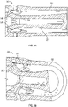
- the mixer 10 may be included in a dry low emission (DLE) engine.
- the mixer 10 may include an outer vane 12 and an inner vane 14.
- the outer vane 12 may include one or more openings 16.
- Fuel may be injected or introduced through the one or more openings 16.
- the inner vane 14 may include an opening 18.
- a swirling air flow may be injected or introduced through the opening 18.
- the swirling air flow from the inner vane 14 may separate on an outer surface of the center body 20.
- the passageways of the mixer 10 may be annular in cross-section as shown.
- the arrangement of the mixer 10 is not suitable for hydrogen (H2) fuels as the arrangement results in a re-circulation region on the outer surface of the center body 20 that may increase the flame-holding risk associated with H2 fuels.
- the length of the mixer 10 may be such that the residence time of the fuel-air mixture within the mixer 10 may result in a high flame-holding risk.
- the mixer 10 may result in low-velocity zones near the vanes.
- An arrangement such as the mixer 10 may allow lower % volume of H2 fuel blending in a fuel.
- the mixer 50 may be included in a DLE engine.
- the mixer 50 may include an annular mixer passage 52.
- the fuel may be injected from one or more openings 54 on frustrums 56.
- the mixer 50 may further include a central bluff body 58.
- the central bluff body 58 may create an annular mixing passage as shown.
- the air flow for mixing with the fuel may be provided with a separate air circuit..
- the mixer 50 may allow higher % volume of H2 fuel blending in a fuel, as compared to the mixer 10. As in the mixer 10, low-velocity zones may exist within the mixer 50.
- the mixer array 100 may include one or more mixers 102.
- the mixer array 100 may be divided into one or more zones. For example, in FIG. 2 , the mixer array 100 may be divided into three zones: zone A, zone B, and zone C.
- the one or more mixers 102 provided in the zones A, B, and C may all be of the same construction, may all be of different construction, or may include some mixers of the same construction and some mixers of different construction.
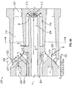
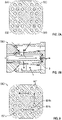
- FIGS. 4A-4E show a mixer 200 according to the present disclosure.
- the mixer 200 may be provided in the mixer array 100 of FIG. 3 ( e.g., the mixer 200 may take the place of one or more mixers 102 in the array 100 of FIG. 3 ).
- the mixer 200 may include one or more tubes 202 ( e.g., mini tubes) placed along a periphery of the mixer 200. That is, the one or more tubes 202 may be placed circumferentially around a central axis A of the mixer 200.
- the tubes 202 may represent generally cylindrical mixer passages arranged as small circular tubes. The placement may be uniformly spaced or nonuniformly spaced about the periphery of the mixer 200.
- the mixer 200 may include a central body 204, also referred to as a central tube 204 having a central passage 206.
- a first annular passage 208 and a second annular passage 210 may be created between the central tube 204 and the one or more tubes 202.
- the central tube 204 may include one or more openings 212 that fluidly couple the central passage 206 to the second annular passage 210.
- One or more passages 214 may fluidly couple the first annular passage 208 to the one or more tubes 202, respectively.
- the one or more tubes 202 may include an interior passage 218 and opposed openings 222, 216.
- One or more openings 215 may fluidly couple the second annular passage 210 to the one or more tubes 202.
- FIG. 4B shows an end view of the exit of the mixer 200.
- An outlet 201 of each tube 202 may be seen in FIG. 4B.
- FIG. 4C shows a view of the mixer 200 taken along the section line A-A of FIG. 4A .
- the fuel-air mixing passage 218, the central passage 206, and the second annular passage 210 are visible in the view of FIG. 4C .
- each tube 202 of the mixer 200 may include the passage 214 that has an opening 216, also referred to as an opposed opening 216, for fluidly coupling the first annular passage 208 ( FIG. 4A ) with the interior passage 218 also referred to as a fuel-air mixing passage 218 of the tube 202.
- the interior passage 218 may be circular in cross-section ( e.g. , generally cylindrical passage as opposed to the generally annular mixing passage of FIGS. 1 and 2 ).
- the interior passage 218 may be a fuel-air mixing passage.
- Each tube 202 may include a fuel passage 220 that may exit into the interior passage 218.
- Each tube 202 may include an opening 222, also referred to as an opposed opening 222, that opens into the interior passage 218.
- Each tube 202 may include an opening 224, also referred to as a tangential opening 224, that opens into the interior passage 218.
- fuel flow A may be introduced or injected axially from a front end of the mixer 200 into the one or more fuel passages 220 in the direction of arrow A.
- the fuel flow A may flow from the fuel passages 220 into the interior passage 218 ( FIG. 4D ) of the tube 202.
- Air may be introduced into the mixer 200 in a number of locations.
- a central air flow B may be introduced in the central passage 206 in the direction of the arrow B.
- the central air flow B may flow from the central passage 206, through the one or more openings 212, into the second annular passage 210 and exit through the opening 215 into the interior passage 218 of the tube 202.
- An air flow C may be introduced through the first annular passage 208 and may exit through the passage 214 into the interior passage 218 of the tube 202 in the direction of arrow C.
- An air flow D also referred to as an opposed air jet D and opposed air flow D, may be introduced through the opposed opening 222 into the interior passage 218 in the direction of arrow D.
- An air flow E also referred to as a tangential air jet E and a tangential air flow E, may be introduced through the tangential opening 224 into the interior of the interior passage 218 in the direction of arrow E.
- the mixer 200 of FIGS. 4A-4G may present an air flow that allows for high velocity flows through the mixer 200. All flows A, B, C, D, and E may converge in the interior passage 218.
- the first set of opposed jet flow e.g ., flows C and D
- the tangential air flow E may create a tangential flow/velocity that creates jets along the wall ( e.g ., as shown in FIGS.
- the tangential opening 224 may be positioned aft of the opposed openings 216 and 222 to clean wakes created behind the jets.
- FIGS. 4A-4G may prevent or inhibit flame-holding.
- the tangential air flow may improve air-fuel mixing within the tube 202.
- the tangential hole(s) may drive the fuel tangentially.
- the tangential air flow E may be introduced at any angle (e.g ., the angle of tangential openings 224) relative to the opposed openings 222.
- the included angle of the opposed openings 222 and 216 may be from about 20 degrees to about 170 degrees, or any value or range therebetween.
- the tangential hole(s) may be positioned aft of the opposed holes. This placement may allow for cleaning of wakes behind the jets from the opposed holes and may generate high velocity near the tube wall, in addition to assisting in mixing of the fuel and air.
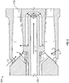
- a mixer 300 is shown.
- the mixer 300 may be the same or similar to the mixer 200 with the following differences.
- the fuel flow A may be injected or introduced through the central passage 206 and then may be introduced to the interior passage 218 radially.
- Opposed air flows C and D and tangential air flow E may be presented in the same manner as FIG. 4 and may operate to increase mixing and accelerate the flow as otherwise described herein.
- fuel flow A introduced through the central passage 206 may enable the fuel to be discharged into different mini tube of a given mixer at different axial location which in turn may help to achieve different fuel-air distribution at the exit of the mini tubes of a given mixer.
- Such an arrangement may ,abate combustion dynamics.
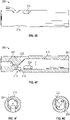
- FIGS. 6A-6C a schematic of an array of mixers 400 is shown. Although four mixers 400 are shown, more or fewer may be provided. The mixers 400 may be the same or similar to other mixers described herein.
- one or more pilot tubes 401 and one or more main tubes 402 may be provided in the array of mixers 400.
- the pilot tubes 401 may introduce the pilot fuel to the engine (e.g., fuel for initiating the engine) and the main tubes 402 may introduce the main fuel to the engine (e.g., fuel for operating the engine).
- the pilot fuel and the main fuel may be different.
- the pilot tubes 401 may allow for enhanced operability, lower carbon monoxide emissions, and enhanced turn down capability as compared to embodiments without one or more pilot tubes.
- the higher fuel-air ratio at the exit of the pilot tube(s) 401 may be achieved by independently controlling fuel flow through pilot circuit, reducing the length of the pilot tube(s) 401, injecting fuel at the aft end of the mixer 400, or any combination thereof.
- Each mixer may have a fuel injector in the center that may act as a pilot tube.
- two pilot tubes 401 are shown, more or fewer may be provided, including no pilot tubes 401 being provided. Any location of pilot tubes 401 along the periphery of the mixer 400 may be provided. The location and number of pilot tubes 401 may be the same or different in a mixer 400 as compared to other mixers 400 in the array.
- the pilot tube 401a may be shorter with respect to the main tubes 402a.
- the reduced length of the pilot tube 401a as compared to the main tube 402a may result in different fuel distribution at the exit of the mixer.
- the axial location of fuel injection may be different for the pilot tube 401b and the main tube 402b. This may change the heat release radially and circumferentially in a manner to influence combustion dynamics.
- a main fuel may be injected at A at a forward location with respect to the pilot fuel, with may be inject at B at an aft location.
- Separate fuel supply lines may be provided to control fuel injection independently in the pilot tube 401a and the main tube 402b.
- the main tube 402b may result in fuel air mixture that is more mixed than the pilot tube 401b.
- the pilot and main tubes of FIG. 6B and 6C may be combined, may each be separately provided in the array of FIG. 6A , or only one may be selected to be placed in the arrange of FIG. 6A , or any combination thereof.
- Opposed air flows C and D and tangential air flow E may also be presented in FIGS. 6B and 6C as previously described herein.
- two pilot tubes 401 are shown in FIG. 6A , any number of pilot tubes may be provided at any location around the periphery of the mixer 400.
- the size of the openings and tube diameter may be smaller for the pilot tube 401 to control pilot air flow from 2% to 20% of the total premixer flow.
- the size of each air and fuel opening for each tube may be different to change the fuel-air ratio for different tubes to alter heat release for combustion dynamics improvement.
- FIGS. 7A and 7B a schematic of an array of mixers 500 is shown. Although four mixers 500 are shown, more or fewer may be provided.
- the mixers 500 may be the same or similar to other mixers described herein.
- Each mixer 500, or one or more of the mixers 500 may include fuel flow A injected in a center of the mixer ( e.g ., similar to FIG. 5 ) to act as a pilot.
- the array of mixers 500 may allow for enhanced operability, lower carbon monoxide emissions, and enhanced turn down capability as compared to mixers not provided with a pilot.
- the mixers 500 are shown to have pilot in the center, alternate locations, such as, for example, but not limited to, a radial location within a given mixer. The location of the pilot may be the same or different for each mixer 500.
- FIG. 8 shows a schematic of an array of mixers 600.
- Tubes 601 of the mixer 600 may be staggered with respect to an adjacent mixer.
- tube 601a is out of alignment or staggered with respect to tubes 601b and 601c.
- a similar arrangement is shown with respect to the remaining tubes 601.
- the tubes 601 may be directedly inline ( e.g., as shown in FIG. 7A ).
- a staggered alignment may improve emissions.
- the mixer 10 of FIG. 1 may include a re-circulation zone on the center body 20 ( FIG. 1 ) where high percentage hydrogen fuel may get trapped. This may result in flame-holding. Thus, the mixer 10 may not be able to burn higher H2 fuel content due to flashback/flame-holding risk..,
- the fuel may be injected axially near the center of the mixer. Downstream of the first set of jets, the opposed jets may improve the lateral spread of the fuel from the center of the mixer. Downstream of the tangential jet, the tangential jet may improve the tangential spread of the fuel from the center of the mixture. At the mixer exit, there may be uniform fuel distribution within the mixer having a mixedness of fuel with the air of about 97%.
- the mixer of the present disclosure creates shorter flame length (as compared to a mixer such as described in FIGS. 1 and 2 ) and a uniform temperature in the combustor.
- the flame length is about 50% shorter compared to the flame length in the mixer of FIGS. 1 and 2 .
- the increased mixedness of the fuel and air and the reduction or elimination of low-velocity pockets may result in the shorter flame length, achieve more uniform temperature in the combustor, reduce flashback/flame-holding risk, or any combination thereof.
- the mixers of the present disclosure may be a mini mixer having a cluster of minitubes (e.g ., a cluster of tubes) having a center axis placed at a radial location with respect to the center of the mixer that is greater than 0.8 times the inner mixer outer diameter.
- Each of the tubes e.g ., minitubes
- the array of such mixers may form different zones within combustor ( e.g ., as shown in FIG. 2 ).
- the mixer of the present disclosure may allow for fuel to be injected axially on a slanted or angled surface where the fuel may be blasted by air moving on a slanted or angled surface (e.g., from the tangential hole(s)) and by opposed air ( e.g., from the opposing holes).
- the fuel may also be injected from the center body in constant area section.
- the mixer of the present disclosure may include a mixer tip having a central region that may be cooled by air, fuel, or a combination thereof, before the same is exhausted into mixer passage.
- the mixer of the present disclosure may include multiple small tubes that may generate small compact flames, thereby increasing residence time in the post flame zone that may lower carbon monoxide emissions, as compared to prior art mixers.
- the mixer of the present disclosure may be oriented such that tubes on a particular mixer may be directly inline or staggered with respect to the tubes of an adjacent mixer. Such an arrangement may improve emissions.
- the mixer of the present disclosure has applications in aero-derivative engines, other gas turbine engines, and applications outside of the gas turbine application.
- the mixer of the present disclosure may reduce and/or eliminate carbon emissions by allowing burn of varying blends of hydrogen fuel.
- the hydrogen fuel percentage may vary from a volume percentage of the fuel blend between 0% to 100%.
- the hydrogen fuel percentage may vary from a volume percentage of the fuel blend between 10% to 100%.
- the hydrogen fuel percentage may vary from a volume percentage of the fuel blend between 20% to 100%.
- the hydrogen fuel percentage may vary from a volume percentage of the fuel blend between 30% to 100%.
- the hydrogen fuel percentage may vary from a volume percentage of the fuel blend between 40% to 100%.
- the hydrogen fuel percentage may vary from a volume percentage of the fuel blend between 50% to 100%.
- the hydrogen fuel percentage may vary from a volume percentage of the fuel blend between 60% to 100%.
- the hydrogen fuel percentage may vary from a volume percentage of the fuel blend between 70% to 100%.
- the hydrogen fuel percentage may vary from a volume percentage of the fuel blend between 80% to 100%.
- the hydrogen fuel percentage may vary from a volume percentage of the fuel blend between 90% to 100%.
- the hydrogen fuel percentage may vary from a volume percentage of the fuel blend between 55% to 95%.
- the hydrogen fuel percentage may vary from a volume percentage of the fuel blend between 60% to 90%.
- the hydrogen fuel percentage may vary from a volume percentage of the fuel blend between 65% to 85%.
- the hydrogen fuel percentage may vary from a volume percentage of the fuel blend between 70% to 80%.
- the hydrogen fuel percentage may vary from a volume percentage of the fuel blend between 85% to 100%.
- the hydrogen fuel percentage may vary from a volume percentage of the fuel blend between 95% to 100%.
- the hydrogen fuel percentage may vary from a volume percentage of the fuel blend of about 55%, 65%, 70%, 75%, 80%, 85%, 90%, 95%, or 100%.
- the mixer of the present disclosure may allow for burning of 100% hydrogen fuel in an engine.
- the mixer of the present disclosure may allow for burning of natural gas, high hydrocarbon (C2+) fuel, hydrogen, or any combination thereof.
- the burning of the aforementioned fuels or combinations thereof may lower NOx emissions as compared to prior art mixers.
- the burning of up to 100% hydrogen fuel capability may allow for zero carbon footprint.
- the fuel flow of the present disclosure may represent fuel provided for the engine.
- the fuel flow may be a pure fuel flow (e.g., pure natural gas, pure hydrogen, etc.) or may be a blended fuel flow (e.g., a percentage by volume of two or more fuels, such as, for example, natural gas and hydrogen).
- the mixer of the present disclosure may be provided in an engine that may be started with natural gas fuel having no hydrogen fuel mixed therein, then hydrogen fuel may be blended into the natural gas fuel and ramped up to 70%-100% of the fuel mixture at a lower power condition to reduce the carbon monoxide emissions. Then, the hydrogen fuel percentage may be reduced at a higher power condition to about 50% of the fuel mixture to achieve lower nitrogen oxide emissions.
- the mixer may be operated with 100% hydrogen fuel throughout engine operation ( e.g ., at low and high-power conditions).
- the particular fuel blend e.g. , including any percentage of hydrogen from 0% to 100%
- the mixer of the present disclosure may provide an air-fuel mixture/ratio that may remove auto-ignition, flash-back, and flame-holding risk normally associated with a pure premixed burner/mixer design with high hydrogen fuel blends.
- the mixer of the present disclosure may be presented to generate an arrange of compact and swirled flames.
- the mixer of the present disclosure may allow for an aero-derivative, 100% hydrogen fueled, DLE engines. This may allow up to 100% hydrogen capability (zero carbon footprint) for merging with renewables, while requiring little or no water for meeting lower NOx emissions requirements.
Landscapes
- Engineering & Computer Science (AREA)
- Chemical & Material Sciences (AREA)
- Combustion & Propulsion (AREA)
- Mechanical Engineering (AREA)
- General Engineering & Computer Science (AREA)
Priority Applications (1)
| Application Number | Priority Date | Filing Date | Title |
|---|---|---|---|
| EP26154852.3A EP4711676A3 (de) | 2021-03-11 | 2022-02-01 | Brennstoffmischer für eine gasturbinenbrennkammer |
Applications Claiming Priority (1)
| Application Number | Priority Date | Filing Date | Title |
|---|---|---|---|
| US17/199,257 US11692709B2 (en) | 2021-03-11 | 2021-03-11 | Gas turbine fuel mixer comprising a plurality of mini tubes for generating a fuel-air mixture |
Related Child Applications (2)
| Application Number | Title | Priority Date | Filing Date |
|---|---|---|---|
| EP26154852.3A Division-Into EP4711676A3 (de) | 2021-03-11 | 2022-02-01 | Brennstoffmischer für eine gasturbinenbrennkammer |
| EP26154852.3A Division EP4711676A3 (de) | 2021-03-11 | 2022-02-01 | Brennstoffmischer für eine gasturbinenbrennkammer |
Publications (3)
| Publication Number | Publication Date |
|---|---|
| EP4056901A2 true EP4056901A2 (de) | 2022-09-14 |
| EP4056901A3 EP4056901A3 (de) | 2022-11-09 |
| EP4056901B1 EP4056901B1 (de) | 2026-04-01 |
Family
ID=80118883
Family Applications (2)
| Application Number | Title | Priority Date | Filing Date |
|---|---|---|---|
| EP22154544.5A Active EP4056901B1 (de) | 2021-03-11 | 2022-02-01 | Brennstoffmischer für eine gasturbinenbrennkammer |
| EP26154852.3A Pending EP4711676A3 (de) | 2021-03-11 | 2022-02-01 | Brennstoffmischer für eine gasturbinenbrennkammer |
Family Applications After (1)
| Application Number | Title | Priority Date | Filing Date |
|---|---|---|---|
| EP26154852.3A Pending EP4711676A3 (de) | 2021-03-11 | 2022-02-01 | Brennstoffmischer für eine gasturbinenbrennkammer |
Country Status (3)
| Country | Link |
|---|---|
| US (2) | US11692709B2 (de) |
| EP (2) | EP4056901B1 (de) |
| CN (1) | CN115076727B (de) |
Cited By (3)
| Publication number | Priority date | Publication date | Assignee | Title |
|---|---|---|---|---|
| EP4230913A1 (de) * | 2022-02-18 | 2023-08-23 | General Electric Company | Brennkammerbrennstoffanordnung |
| EP4350218A1 (de) * | 2022-10-03 | 2024-04-10 | Honeywell International Inc. | Düse für gasförmigen brennstoff zur verwendung in gasturbinenmotoren |
| EP4086517B1 (de) * | 2021-05-07 | 2024-11-06 | General Electric Company | Gabelförmiger pilotvormischer für eine hauptkleinmischeranordnung in einem gasturbinenmotor |
Families Citing this family (9)
| Publication number | Priority date | Publication date | Assignee | Title |
|---|---|---|---|---|
| US11815269B2 (en) * | 2021-12-29 | 2023-11-14 | General Electric Company | Fuel-air mixing assembly in a turbine engine |
| US12085282B2 (en) * | 2022-02-23 | 2024-09-10 | Air Products And Chemicals, Inc. | Hydrogen injection for enhanced combustion stability in gas turbine systems |
| GB202219380D0 (en) | 2022-12-21 | 2023-02-01 | Rolls Royce Plc | Gas turbine operating conditions |
| GB202219385D0 (en) * | 2022-12-21 | 2023-02-01 | Rolls Royce Plc | Aircraft combustion systems |
| GB202219384D0 (en) | 2022-12-21 | 2023-02-01 | Rolls Royce Plc | Aircraft fuelling |
| US12111056B2 (en) * | 2023-02-02 | 2024-10-08 | Pratt & Whitney Canada Corp. | Combustor with central fuel injection and downstream air mixing |
| US20260009541A1 (en) * | 2024-07-02 | 2026-01-08 | General Electric Company | Turbine engine with a fuel injector |
| US12410746B1 (en) | 2024-07-08 | 2025-09-09 | General Electric Company | Gas turbine and fuel nozzle assembly for mixing hydrogen fuel and steam to control flame speed |
| CN118896307B (zh) * | 2024-08-20 | 2025-09-16 | 厦门大学 | 基于螺旋结构的纯氢燃料的微混旋流喷嘴和燃烧室 |
Family Cites Families (44)
| Publication number | Priority date | Publication date | Assignee | Title |
|---|---|---|---|---|
| US5836164A (en) | 1995-01-30 | 1998-11-17 | Hitachi, Ltd. | Gas turbine combustor |
| US6446439B1 (en) * | 1999-11-19 | 2002-09-10 | Power Systems Mfg., Llc | Pre-mix nozzle and full ring fuel distribution system for a gas turbine combustor |
| JP4134311B2 (ja) | 2002-03-08 | 2008-08-20 | 独立行政法人 宇宙航空研究開発機構 | ガスタービン燃焼器 |
| DE10345137B4 (de) * | 2003-09-29 | 2014-02-13 | Alstom Technology Ltd. | Verfahren zum Betrieb einer Brennstoffeinspritzvorrichtung sowie eine Brennstoffeinspritzvorrichtung zur Durchführung des Verfahrens |
| US7065972B2 (en) * | 2004-05-21 | 2006-06-27 | Honeywell International, Inc. | Fuel-air mixing apparatus for reducing gas turbine combustor exhaust emissions |
| JP4997217B2 (ja) * | 2008-12-05 | 2012-08-08 | 株式会社日立製作所 | ガスタービンの運転方法及びガスタービン燃焼器 |
| US8205452B2 (en) * | 2009-02-02 | 2012-06-26 | General Electric Company | Apparatus for fuel injection in a turbine engine |
| US8607570B2 (en) * | 2009-05-06 | 2013-12-17 | General Electric Company | Airblown syngas fuel nozzle with diluent openings |
| US20110016866A1 (en) * | 2009-07-22 | 2011-01-27 | General Electric Company | Apparatus for fuel injection in a turbine engine |
| US8683804B2 (en) * | 2009-11-13 | 2014-04-01 | General Electric Company | Premixing apparatus for fuel injection in a turbine engine |
| US8919673B2 (en) | 2010-04-14 | 2014-12-30 | General Electric Company | Apparatus and method for a fuel nozzle |
| US20120180487A1 (en) * | 2011-01-19 | 2012-07-19 | General Electric Company | System for flow control in multi-tube fuel nozzle |
| RU2626887C2 (ru) * | 2011-08-22 | 2017-08-02 | Маджед ТОКАН | Тангенциальная кольцевая камера сгорания с предварительно смешанным топливом и воздухом для использования в газотурбинных двигателях |
| EP2581561B8 (de) * | 2011-10-12 | 2017-07-12 | Ansaldo Energia IP UK Limited | Betriebsverfahren für Wasserstoff-/Erdgasgemische innerhalb einer Wiedererhitzungsgasturbine und Gasturbine |
| JP5816522B2 (ja) | 2011-11-02 | 2015-11-18 | 川崎重工業株式会社 | ガスタービンシステム |
| US9441836B2 (en) * | 2012-07-10 | 2016-09-13 | United Technologies Corporation | Fuel-air pre-mixer with prefilmer |
| JP5908379B2 (ja) | 2012-09-24 | 2016-04-26 | 三菱日立パワーシステムズ株式会社 | ガスタービン燃焼器 |
| US20140109582A1 (en) | 2012-10-23 | 2014-04-24 | General Electric Company | Self-stabilized micromixer |
| US9528444B2 (en) * | 2013-03-12 | 2016-12-27 | General Electric Company | System having multi-tube fuel nozzle with floating arrangement of mixing tubes |
| US9651259B2 (en) * | 2013-03-12 | 2017-05-16 | General Electric Company | Multi-injector micromixing system |
| JP6021705B2 (ja) * | 2013-03-22 | 2016-11-09 | 三菱重工業株式会社 | 燃焼器、および、ガスタービン |
| JP6190670B2 (ja) * | 2013-08-30 | 2017-08-30 | 三菱日立パワーシステムズ株式会社 | ガスタービン燃焼システム |
| US9500367B2 (en) * | 2013-11-11 | 2016-11-22 | General Electric Company | Combustion casing manifold for high pressure air delivery to a fuel nozzle pilot system |
| US20150167983A1 (en) * | 2013-12-13 | 2015-06-18 | General Electric Company | Bundled tube fuel injector tube tip |
| US9528702B2 (en) * | 2014-02-21 | 2016-12-27 | General Electric Company | System having a combustor cap |
| US9534788B2 (en) * | 2014-04-03 | 2017-01-03 | General Electric Company | Air fuel premixer for low emissions gas turbine combustor |
| US10207325B2 (en) | 2014-06-16 | 2019-02-19 | Delavan Inc. | Additive manufacture from machined surface |
| EP3026347A1 (de) * | 2014-11-25 | 2016-06-01 | Alstom Technology Ltd | Brennkammer mit ringförmigem Wirbelkörper |
| JP2016148507A (ja) * | 2014-12-30 | 2016-08-18 | ゼネラル・エレクトリック・カンパニイ | ガスタービン燃焼器におけるパイロットノズル |
| US10352567B2 (en) * | 2015-10-09 | 2019-07-16 | General Electric Company | Fuel-air premixer for a gas turbine |
| US10641176B2 (en) | 2016-03-25 | 2020-05-05 | General Electric Company | Combustion system with panel fuel injector |
| US10465909B2 (en) | 2016-11-04 | 2019-11-05 | General Electric Company | Mini mixing fuel nozzle assembly with mixing sleeve |
| US10295190B2 (en) * | 2016-11-04 | 2019-05-21 | General Electric Company | Centerbody injector mini mixer fuel nozzle assembly |
| US10352569B2 (en) * | 2016-11-04 | 2019-07-16 | General Electric Company | Multi-point centerbody injector mini mixing fuel nozzle assembly |
| US10393382B2 (en) * | 2016-11-04 | 2019-08-27 | General Electric Company | Multi-point injection mini mixing fuel nozzle assembly |
| EP3324120B1 (de) | 2016-11-18 | 2019-09-18 | Ansaldo Energia Switzerland AG | Mit additiver fertigung erzeugte gasturbinen-brennstoffinjektoranordnung |
| US10890329B2 (en) * | 2018-03-01 | 2021-01-12 | General Electric Company | Fuel injector assembly for gas turbine engine |
| US10935245B2 (en) * | 2018-11-20 | 2021-03-02 | General Electric Company | Annular concentric fuel nozzle assembly with annular depression and radial inlet ports |
| US11156360B2 (en) * | 2019-02-18 | 2021-10-26 | General Electric Company | Fuel nozzle assembly |
| US11506388B1 (en) * | 2021-05-07 | 2022-11-22 | General Electric Company | Furcating pilot pre-mixer for main mini-mixer array in a gas turbine engine |
| US11815269B2 (en) * | 2021-12-29 | 2023-11-14 | General Electric Company | Fuel-air mixing assembly in a turbine engine |
| US12031486B2 (en) * | 2022-01-13 | 2024-07-09 | General Electric Company | Combustor with lean openings |
| US11828465B2 (en) * | 2022-01-21 | 2023-11-28 | General Electric Company | Combustor fuel assembly |
| US12215866B2 (en) * | 2022-02-18 | 2025-02-04 | General Electric Company | Combustor for a turbine engine having a fuel-air mixer including a set of mixing passages |
-
2021
- 2021-03-11 US US17/199,257 patent/US11692709B2/en active Active
-
2022
- 2022-02-01 EP EP22154544.5A patent/EP4056901B1/de active Active
- 2022-02-01 EP EP26154852.3A patent/EP4711676A3/de active Pending
- 2022-03-09 CN CN202210232555.3A patent/CN115076727B/zh active Active
-
2023
- 2023-05-19 US US18/320,682 patent/US12111057B2/en active Active
Cited By (4)
| Publication number | Priority date | Publication date | Assignee | Title |
|---|---|---|---|---|
| EP4086517B1 (de) * | 2021-05-07 | 2024-11-06 | General Electric Company | Gabelförmiger pilotvormischer für eine hauptkleinmischeranordnung in einem gasturbinenmotor |
| EP4230913A1 (de) * | 2022-02-18 | 2023-08-23 | General Electric Company | Brennkammerbrennstoffanordnung |
| EP4350218A1 (de) * | 2022-10-03 | 2024-04-10 | Honeywell International Inc. | Düse für gasförmigen brennstoff zur verwendung in gasturbinenmotoren |
| US12372239B2 (en) | 2022-10-03 | 2025-07-29 | Honeywell International Inc. | Gaseous fuel nozzle for use in gas turbine engines |
Also Published As
| Publication number | Publication date |
|---|---|
| CN115076727B (zh) | 2025-03-25 |
| EP4056901B1 (de) | 2026-04-01 |
| EP4711676A3 (de) | 2026-04-22 |
| US12111057B2 (en) | 2024-10-08 |
| US11692709B2 (en) | 2023-07-04 |
| US20230288069A1 (en) | 2023-09-14 |
| CN115076727A (zh) | 2022-09-20 |
| EP4711676A2 (de) | 2026-03-18 |
| EP4056901A3 (de) | 2022-11-09 |
| US20220290863A1 (en) | 2022-09-15 |
Similar Documents
| Publication | Publication Date | Title |
|---|---|---|
| EP4056901A2 (de) | Brennstoffmischer für eine gasturbinenbrennkammer | |
| RU2537109C2 (ru) | Входное устройство для предварительного смешивания топлива и воздуха, а также узел, содержащий такое устройство, систему выделения/преобразования энергии и газовую турбину (варианты) | |
| US5511375A (en) | Dual fuel mixer for gas turbine combustor | |
| CN101793408B (zh) | 燃烧器喷嘴 | |
| US5865024A (en) | Dual fuel mixer for gas turbine combustor | |
| JP3459449B2 (ja) | ガスタービン燃焼器、及び1次運転モードから予混合運転モードへの移行中に燃焼動圧を抑制する方法 | |
| US5816049A (en) | Dual fuel mixer for gas turbine combustor | |
| CN101713548B (zh) | 用于副燃料喷嘴的管状燃料喷射器 | |
| US5251447A (en) | Air fuel mixer for gas turbine combustor | |
| US6374615B1 (en) | Low cost, low emissions natural gas combustor | |
| EP4056902B1 (de) | Brennstoffmischer | |
| EP0500256A1 (de) | Luft-/Kraftstoff-Mischer für eine Gasturbinenbrennkammer | |
| CN101644435A (zh) | 稀薄直喷式扩散头和相关方法 | |
| JP2012229697A (ja) | ガスタービンエンジン内で燃料を燃焼させるための方法及び装置 | |
| CN115307177B (zh) | 用于燃气涡轮发动机中的主微型混合器阵列的分叉先导预混合器 | |
| JP2024080498A (ja) | 水素ガスタービンに適した燃焼器及びその燃焼ノズル | |
| CN115451431A (zh) | 一种用于燃气轮机燃烧室的燃料喷嘴预混系统 | |
| EP3425281B1 (de) | Pilotdüse mit inline-vormischung | |
| JPH0814565A (ja) | ガスタービン燃焼器 | |
| CN115046225B (zh) | 燃烧室头部、燃烧室和航空发动机 | |
| JP3841285B2 (ja) | 旋回型低NOx燃焼器 | |
| JP2006090602A (ja) | ローブミキサー及び予混合器 |
Legal Events
| Date | Code | Title | Description |
|---|---|---|---|
| PUAI | Public reference made under article 153(3) epc to a published international application that has entered the european phase |
Free format text: ORIGINAL CODE: 0009012 |
|
| STAA | Information on the status of an ep patent application or granted ep patent |
Free format text: STATUS: THE APPLICATION HAS BEEN PUBLISHED |
|
| AK | Designated contracting states |
Kind code of ref document: A2 Designated state(s): AL AT BE BG CH CY CZ DE DK EE ES FI FR GB GR HR HU IE IS IT LI LT LU LV MC MK MT NL NO PL PT RO RS SE SI SK SM TR |
|
| PUAL | Search report despatched |
Free format text: ORIGINAL CODE: 0009013 |
|
| AK | Designated contracting states |
Kind code of ref document: A3 Designated state(s): AL AT BE BG CH CY CZ DE DK EE ES FI FR GB GR HR HU IE IS IT LI LT LU LV MC MK MT NL NO PL PT RO RS SE SI SK SM TR |
|
| RIC1 | Information provided on ipc code assigned before grant |
Ipc: F23R 3/34 20060101ALI20221004BHEP Ipc: F23R 3/28 20060101AFI20221004BHEP |
|
| STAA | Information on the status of an ep patent application or granted ep patent |
Free format text: STATUS: REQUEST FOR EXAMINATION WAS MADE |
|
| 17P | Request for examination filed |
Effective date: 20230427 |
|
| RBV | Designated contracting states (corrected) |
Designated state(s): AL AT BE BG CH CY CZ DE DK EE ES FI FR GB GR HR HU IE IS IT LI LT LU LV MC MK MT NL NO PL PT RO RS SE SI SK SM TR |
|
| STAA | Information on the status of an ep patent application or granted ep patent |
Free format text: STATUS: EXAMINATION IS IN PROGRESS |
|
| 17Q | First examination report despatched |
Effective date: 20240125 |
|
| GRAP | Despatch of communication of intention to grant a patent |
Free format text: ORIGINAL CODE: EPIDOSNIGR1 |
|
| STAA | Information on the status of an ep patent application or granted ep patent |
Free format text: STATUS: GRANT OF PATENT IS INTENDED |
|
| INTG | Intention to grant announced |
Effective date: 20251126 |
|
| GRAS | Grant fee paid |
Free format text: ORIGINAL CODE: EPIDOSNIGR3 |
|
| GRAA | (expected) grant |
Free format text: ORIGINAL CODE: 0009210 |
|
| STAA | Information on the status of an ep patent application or granted ep patent |
Free format text: STATUS: THE PATENT HAS BEEN GRANTED |
|
| RAP3 | Party data changed (applicant data changed or rights of an application transferred) |
Owner name: GENERAL ELECTRIC COMPANY |
|
| P01 | Opt-out of the competence of the unified patent court (upc) registered |
Free format text: CASE NUMBER: UPC_APP_0004742_4056901/2026 Effective date: 20260210 |
|
| AK | Designated contracting states |
Kind code of ref document: B1 Designated state(s): AL AT BE BG CH CY CZ DE DK EE ES FI FR GB GR HR HU IE IS IT LI LT LU LV MC MK MT NL NO PL PT RO RS SE SI SK SM TR |
|
| REG | Reference to a national code |
Ref country code: CH Ref legal event code: F10 Free format text: ST27 STATUS EVENT CODE: U-0-0-F10-F00 (AS PROVIDED BY THE NATIONAL OFFICE) Effective date: 20260401 Ref country code: GB Ref legal event code: FG4D |
|
| REG | Reference to a national code |
Ref country code: IE Ref legal event code: FG4D |
|
| REG | Reference to a national code |
Ref country code: DE Ref legal event code: R096 Ref document number: 602022033256 Country of ref document: DE |