EP4056858A1 - Pump casing and pump device - Google Patents
Pump casing and pump device Download PDFInfo
- Publication number
- EP4056858A1 EP4056858A1 EP20885133.7A EP20885133A EP4056858A1 EP 4056858 A1 EP4056858 A1 EP 4056858A1 EP 20885133 A EP20885133 A EP 20885133A EP 4056858 A1 EP4056858 A1 EP 4056858A1
- Authority
- EP
- European Patent Office
- Prior art keywords
- suction
- pump casing
- rib
- outer edge
- hydro
- Prior art date
- Legal status (The legal status is an assumption and is not a legal conclusion. Google has not performed a legal analysis and makes no representation as to the accuracy of the status listed.)
- Granted
Links
Images



Classifications
-
- F—MECHANICAL ENGINEERING; LIGHTING; HEATING; WEAPONS; BLASTING
- F04—POSITIVE - DISPLACEMENT MACHINES FOR LIQUIDS; PUMPS FOR LIQUIDS OR ELASTIC FLUIDS
- F04D—NON-POSITIVE-DISPLACEMENT PUMPS
- F04D29/00—Details, component parts, or accessories
- F04D29/40—Casings; Connections of working fluid
- F04D29/42—Casings; Connections of working fluid for radial or helico-centrifugal pumps
- F04D29/426—Casings; Connections of working fluid for radial or helico-centrifugal pumps especially adapted for liquid pumps
-
- F—MECHANICAL ENGINEERING; LIGHTING; HEATING; WEAPONS; BLASTING
- F04—POSITIVE - DISPLACEMENT MACHINES FOR LIQUIDS; PUMPS FOR LIQUIDS OR ELASTIC FLUIDS
- F04D—NON-POSITIVE-DISPLACEMENT PUMPS
- F04D13/00—Pumping installations or systems
- F04D13/02—Units comprising pumps and their driving means
- F04D13/06—Units comprising pumps and their driving means the pump being electrically driven
-
- F—MECHANICAL ENGINEERING; LIGHTING; HEATING; WEAPONS; BLASTING
- F04—POSITIVE - DISPLACEMENT MACHINES FOR LIQUIDS; PUMPS FOR LIQUIDS OR ELASTIC FLUIDS
- F04D—NON-POSITIVE-DISPLACEMENT PUMPS
- F04D29/00—Details, component parts, or accessories
- F04D29/40—Casings; Connections of working fluid
- F04D29/42—Casings; Connections of working fluid for radial or helico-centrifugal pumps
- F04D29/426—Casings; Connections of working fluid for radial or helico-centrifugal pumps especially adapted for liquid pumps
- F04D29/4293—Details of fluid inlet or outlet
-
- F—MECHANICAL ENGINEERING; LIGHTING; HEATING; WEAPONS; BLASTING
- F05—INDEXING SCHEMES RELATING TO ENGINES OR PUMPS IN VARIOUS SUBCLASSES OF CLASSES F01-F04
- F05D—INDEXING SCHEME FOR ASPECTS RELATING TO NON-POSITIVE-DISPLACEMENT MACHINES OR ENGINES, GAS-TURBINES OR JET-PROPULSION PLANTS
- F05D2240/00—Components
- F05D2240/10—Stators
- F05D2240/12—Fluid guiding means, e.g. vanes
- F05D2240/126—Baffles or ribs
-
- F—MECHANICAL ENGINEERING; LIGHTING; HEATING; WEAPONS; BLASTING
- F05—INDEXING SCHEMES RELATING TO ENGINES OR PUMPS IN VARIOUS SUBCLASSES OF CLASSES F01-F04
- F05D—INDEXING SCHEME FOR ASPECTS RELATING TO NON-POSITIVE-DISPLACEMENT MACHINES OR ENGINES, GAS-TURBINES OR JET-PROPULSION PLANTS
- F05D2260/00—Function
- F05D2260/94—Functionality given by mechanical stress related aspects such as low cycle fatigue [LCF] of high cycle fatigue [HCF]
- F05D2260/941—Functionality given by mechanical stress related aspects such as low cycle fatigue [LCF] of high cycle fatigue [HCF] particularly aimed at mechanical or thermal stress reduction
Definitions
- the present invention relates to a pump casing, and more particularly to a reinforcing structure of a pump casing for accommodating an impeller therein.
- the present invention also relates to a pump apparatus including such a pump casing.
- a volute pump is configured to pressurize a liquid in a pump casing by rotating an impeller in the pump casing and discharge the pressurized liquid to an exterior through a discharge port.
- the pressure of the liquid acts on the pump casing, a high stress is generated in a part of the pump casing, and the pump casing may be deformed. Such deformation of the pump casing may cause the pressurized liquid to leak out of the pump casing. Therefore, the pump casing is required to have a strength to keep the deformation of the pump casing below a certain level.
- the pump casing having a volute chamber has a complicated shape. Therefore, the pump casing is typically made by casting. If the entire pump casing has a thick wall in order to increase the strength of the pump casing, the weight of the pump casing increases, and as a result, the weight of the entire volute pump increases.
- This water-pressure resistance test is conducted for the purpose of inspecting the volute pump for water leakage. Specifically, an impeller and a rotation shaft are removed from the pump casing, and all openings including a suction port and a discharge port of the pump casing are closed to form a closed space inside the pump casing. This closed space is then filled with water having a pressure 1.5 times a maximum discharge pressure of the pump. The pump casing, filled with the water, is left as it is for three minutes or more so that the pump casing is inspected for water leakage and deformation.
- an inching test may be conducted.
- This inching test is a test in which the pump casing is inspected for water leakage by repeatedly increasing the pressure in the pump casing from no pressure condition to a certain level of pressure.
- the pump casing is required to have a high strength from the viewpoint of ensuring safe operation.
- FIG. 8 is a cross-sectional view showing an example of a conventional pump casing.
- a pump casing 200 has a suction hydro structure 201 having a suction port 201a, and a volute hydro structure 202 having a volute chamber 202a in which an impeller is housed and a discharge port 202b.
- a rib 205 extends from the suction hydro structure 201 to a discharge flange 206. Such a rib 205 can increase a second moment of area of the pump casing 200 and can therefore improve the strength of the pump casing 200.
- Patent document 1 Japanese laid-open patent publication No. 2007-291921
- This connecting portion X is a portion where the rib 205 and the suction hydro structure 201 are connected.
- a crack may be generated in an outer surface of the connecting portion X. This crack propagates toward the inside of the suction hydro structure 201 and may eventually reach an inner surface of the suction hydro structure 201.
- the crack that has reached the inside of the pump casing 200 causes liquid leakage from the pump casing 200. In particular, under an environment where the pump is frequently started and stopped, the crack grows rapidly and the life of the pump casing 200 is shortened.
- the present invention provides a pump casing capable of preventing liquid leakage even if a crack is generated in a rib by making it difficult for the crack to reach an inside of the pump casing.
- the present invention also provides a pump apparatus having such a pump casing.
- a pump casing comprising: a volute hydro structure having a discharge port and a volute chamber for accommodating an impeller therein; a suction hydro structure having a suction port, the suction port communicating with the volute chamber; a rib connected to outer surfaces of the volute hydro structure and the suction hydro structure, wherein the rib has a curved outer edge that is curved inwardly of the rib, the curved outer edge is smoothly connected to an outermost peripheral surface of the suction hydro structure, and a ratio of a radius of curvature of the curved outer edge to a radius of curvature of the outermost peripheral surface of the suction hydro structure is 20% or more.
- a tangent line on the curved outer edge at a connection point between the curved outer edge of the rib and the outermost peripheral surface of the suction hydro structure coincides with a tangent line on the outermost peripheral surface of the suction hydro structure at the connection point.
- the rib is connected to a discharge flange that surrounds the discharge port.
- the curved outer edge of the rib extends from the suction hydro structure to the discharge flange.
- a pump apparatus comprising: an impeller; an electric motor coupled to the impeller; and the pump casing accommodating the impeller therein.
- a stress is concentrated at a position away from the connecting portion between the rib and the suction hydro structure.
- the rib having the curved outer edge of the above-discussed radius of curvature can locate a stress-concentrated position away from the suction hydro structure. Therefore, even if a crack is generated in the curved outer edge of the rib due to the stress concentration, the crack extends toward the inside of the rib and hardly reaches the suction hydro structure. That is, the crack is less likely to reach the suction hydro structure thanks to the height of the rib. As a result, this configuration can prevent the suction hydro structure itself from being cracked.
- FIG. 1 is a cross-sectional view showing an embodiment of a pump apparatus.
- the pump apparatus of the present embodiment is an in-line pump apparatus having a suction port and a discharge port which are aligned in line.
- This type of pump apparatus has no leg, and the entire pump apparatus is supported by pipes coupled to a suction flange and a discharge flange.
- the pump apparatus includes an electric motor 1, a rotation shaft 2 coupled to the electric motor 1 via a shaft coupling 3, an impeller 5 fixed to the rotation shaft 2, and a pump casing 8 accommodating the impeller 5.
- the impeller 5 is a centrifugal impeller.
- the impeller 2 is coupled to the electric motor 1 via the rotation shaft 2, and the rotation shaft 2 and the impeller 5 are integrally rotated by the electric motor 1.
- a casing cover 12 and a motor base 14 are arranged between the electric motor 1 and the pump casing 8. An opening of the pump casing 8 is closed by the casing cover 12.
- the motor base 14 is fixed to the casing cover 12, and the electric motor 1 is fixed to the motor base 14.
- the pump casing 8 is a casting.
- the pump casing 8 includes a suction hydro structure 20 having a suction port 20a, and a volute hydro structure 22 having a discharge port 22a and a volute chamber 22b.
- the impeller 5 is arranged in the volute chamber 22b.
- the suction port 20a and the discharge port 22a communicate with the volute chamber 22b.
- the suction hydro structure 20 has a suction flow passage 24 coupled to the suction port 20a and the volute chamber 22b, and the suction port 20a communicates with the volute chamber 22b through the suction flow passage 24.
- the volume hydro structure 22 has a discharge flow passage 25 coupled to the volume chamber 22b and the discharge port 22a, and the discharge port 22a communicates with the volume chamber 22b through the discharge flow passage 25.
- the pump casing 8 has a suction flange 27 that surrounds the suction port 20a and a discharge flange 28 that surrounds the discharge port 22a.
- the suction port 20a and the discharge port 22a are aligned in a straight line.
- the pump casing 8 has no leg and the entire pump apparatus is supported by pipes (not shown) coupled to the suction flange 27 and the discharge flange 28.
- This pump apparatus having the suction port 20a and the discharge port 22a aligned in a straight line is called an in-line pump apparatus that can be incorporated between pipes.
- the suction hydro structure 20 has an outermost peripheral surface 20b which is curved outwardly along the shape of the suction flow passage 24.
- the pump casing 8 includes a rib 30 smoothly connected to the outermost peripheral surface 20b of the suction hydro structure 20. This rib 30 is provided to increase a strength of the pump casing 8.
- FIG. 2 is a perspective view of the pump casing 8
- FIG. 3 is a bottom view of the pump casing 8
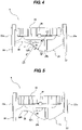
- FIG. 4 is a side view of the pump casing 8.
- the rib 30 extends outwardly in a radial direction of the volute chamber 22b from the suction hydro structure 20. As shown in FIG. 3 , the suction port 20a, the rib 30, and the discharge port 22a are aligned in a straight line.
- the volute hydro structure 22 has an outer peripheral wall 35 surrounding the volute chamber 22b and further has a volute wall 36 connected to the outer peripheral wall 35.
- the discharge port 22a is formed in an end of the volute wall 36.
- the suction hydro structure 20 is connected to a central portion of the volute wall 36.
- the rib 30 is connected to an outer surface of the suction hydro structure 20 and an outer surface of the volute hydro structure 22.
- the outermost peripheral surface 20b of the suction hydro structure 20 is curved outwardly of the suction hydro structure 20.
- the rib 30 is connected smoothly to the curved outermost peripheral surface 20b of the suction hydro structure 20.
- the rib 30 has a curved outer edge 30A that is curved inwardly of the rib 30.
- the curved outer edge 30A is smoothly connected to the outermost peripheral surface 20b of the suction hydro structure 20.
- a tangent line T1 on the curved outer edge 30A of the rib 30 at a connection point C between the outermost peripheral surface 20b of the suction hydro structure 20 and the curved outer edge 30A of the rib 30 coincides with a tangent line T2 on the outermost peripheral surface 20b of the suction hydro structure 20 at the connection point C.
- a ratio (R1/R2 ⁇ 100) of a radius of curvature R1 of the rib 30 to a radius of curvature R2 of the outermost peripheral surface 20b of the suction hydro structure 20 is 20% or more.
- the ratio of the radius of curvature R1 to the radius of curvature R2 is 50% or more, more preferably 100% or more.
- the radius of curvature R1 is equal to the radius of curvature R2.
- the radius of curvature R1 may be larger than the radius of curvature R2. As the radius of curvature R1 increases, the curved outer edge 30A of the rib 30 approaches a straight line.
- An upper limit of the radius of curvature R1 i.e., an upper limit of the ratio of the radius of curvature R1 to the radius of curvature R2 is not particularly limited.
- the curved outer edge 30A of the rib 30 may have a shape as close to a straight line as possible.
- a center O1 of a circle of curvature of the curved outer edge 30A of the rib 30 is located outside the pump casing 8, and a center O2 of a circle of curvature of the outermost peripheral surface 20b of the suction hydro structure 20 is located inside the pump casing 8.
- the radius of curvature R1 of the curved outer edge 30A of the rib 30 is the same as the radius of curvature R2 of the outermost peripheral surface 20b of the suction hydro structure 20.
- the curved outer edge 30A of the rib 30 has a shape similar to the outermost peripheral surface 20b of the suction hydro structure 20.
- a stress-concentrated position can be located away from the suction hydro structure 20.
- the stress-concentrated position is indicated by a reference symbol Y in FIG. 4 and is located away from the suction hydro structure 20. Therefore, even if a crack is generated in the curved outer edge 30A of the rib 30 due to the stress concentration, the crack propagates inside the rib 30 and hardly reaches the suction hydro structure 20. Specifically, the crack is less likely to reach the suction hydro structure 20 thanks to the height of the rib 30. As a result, this configuration can prevent the suction hydro structure 20 itself from being cracked.
- the pump apparatus of the present embodiment is an in-line pump apparatus having the suction port 20a and the discharge port 22a which are aligned in a straight line.
- the in-line pump apparatus is a type of pump apparatus that can be installed between pipes. Specifically, the suction flange 27 is coupled to a suction pipe (not shown) and the discharge flange 28 is coupled to a discharge pipe (not shown), so that the entire pump apparatus is supported by the suction pipe and the discharge pipe. With such an installation, a bending moment is applied to the pump casing 8.
- one end of the curved outer edge 30A of the rib 30 is connected to the outermost peripheral surface 20b of the suction hydro structure 20, and other end of the curved outer edge 30A of the rib 30 is connected to the discharge flange 28. Since the rib 30 extends from the suction hydro structure 20 to the discharge flange 28, the rib 30 can impart a sufficient mechanical strength to the pump casing 8 against the bending moment.
- the rib 30 may not be curved. Specifically, the entire outer edge of the rib 30 may not be curved inwardly.
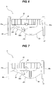
- the rib 30 may have a curved outer edge 30A and a linear outer edge 30B connected to the curved outer edge 30A.
- the rib 30 may have a cut 30C formed in the curved outer edge 30A.
- the rib 30 may not be connected to the discharge flange 28.
- the end of the rib 30 may be connected to the volute wall 36 of the volute hydro structure 22.
- the rib 30 has the curved outer edge 30A smoothly connected to the outermost peripheral surface 20b of the suction hydro structure 20, and the curvature of the curved outer edge 30A is the same as that of the embodiment described with reference to FIG. 4 . Therefore, the rib 30 shown in FIGS. 5 to 7 can located the stress-concentrated position away from the suction hydro structure 20.
- the present invention applicable to a reinforcing structure of a pump casing for housing an impeller therein.
- the present invention is also applicable to a pump apparatus having such a pump casing.
Landscapes
- Engineering & Computer Science (AREA)
- Mechanical Engineering (AREA)
- General Engineering & Computer Science (AREA)
- Structures Of Non-Positive Displacement Pumps (AREA)
Abstract
Description
- The present invention relates to a pump casing, and more particularly to a reinforcing structure of a pump casing for accommodating an impeller therein. The present invention also relates to a pump apparatus including such a pump casing.
- A volute pump is configured to pressurize a liquid in a pump casing by rotating an impeller in the pump casing and discharge the pressurized liquid to an exterior through a discharge port. When the pressure of the liquid acts on the pump casing, a high stress is generated in a part of the pump casing, and the pump casing may be deformed. Such deformation of the pump casing may cause the pressurized liquid to leak out of the pump casing. Therefore, the pump casing is required to have a strength to keep the deformation of the pump casing below a certain level.
- The pump casing having a volute chamber has a complicated shape. Therefore, the pump casing is typically made by casting. If the entire pump casing has a thick wall in order to increase the strength of the pump casing, the weight of the pump casing increases, and as a result, the weight of the entire volute pump increases.
- On the other hand, if the pump casing is made thin, the mechanical strength of the pump casing is lowered, and as a result, the volute pump may not be able to pass a water-pressure resistance test. This water-pressure resistance test is conducted for the purpose of inspecting the volute pump for water leakage. Specifically, an impeller and a rotation shaft are removed from the pump casing, and all openings including a suction port and a discharge port of the pump casing are closed to form a closed space inside the pump casing. This closed space is then filled with water having a pressure 1.5 times a maximum discharge pressure of the pump. The pump casing, filled with the water, is left as it is for three minutes or more so that the pump casing is inspected for water leakage and deformation.
- In addition to the above water-pressure resistance test, an inching test may be conducted. This inching test is a test in which the pump casing is inspected for water leakage by repeatedly increasing the pressure in the pump casing from no pressure condition to a certain level of pressure. The pump casing is required to have a high strength from the viewpoint of ensuring safe operation.
- Thus, in order to increase the strength of the pump casing, a rib may be provided on an outer peripheral surface of the pump casing.
FIG. 8 is a cross-sectional view showing an example of a conventional pump casing. Apump casing 200 has asuction hydro structure 201 having asuction port 201a, and avolute hydro structure 202 having avolute chamber 202a in which an impeller is housed and adischarge port 202b. Arib 205 extends from thesuction hydro structure 201 to adischarge flange 206. Such arib 205 can increase a second moment of area of thepump casing 200 and can therefore improve the strength of thepump casing 200. - Patent document 1:
Japanese laid-open patent publication No. 2007-291921 - However, stress analysis has shown the fact that when a high pressure is applied to the inside of the
pump casing 200, the stress was concentrated on a connecting portion indicated by a reference symbol X inFIG. 8 . This connecting portion X is a portion where therib 205 and thesuction hydro structure 201 are connected. When high stress is concentrated on the connecting portion X, a crack may be generated in an outer surface of the connecting portion X. This crack propagates toward the inside of thesuction hydro structure 201 and may eventually reach an inner surface of thesuction hydro structure 201. The crack that has reached the inside of thepump casing 200 causes liquid leakage from thepump casing 200. In particular, under an environment where the pump is frequently started and stopped, the crack grows rapidly and the life of thepump casing 200 is shortened. - Therefore, the present invention provides a pump casing capable of preventing liquid leakage even if a crack is generated in a rib by making it difficult for the crack to reach an inside of the pump casing. The present invention also provides a pump apparatus having such a pump casing.
- In an embodiment, there is provided a pump casing comprising: a volute hydro structure having a discharge port and a volute chamber for accommodating an impeller therein; a suction hydro structure having a suction port, the suction port communicating with the volute chamber; a rib connected to outer surfaces of the volute hydro structure and the suction hydro structure, wherein the rib has a curved outer edge that is curved inwardly of the rib, the curved outer edge is smoothly connected to an outermost peripheral surface of the suction hydro structure, and a ratio of a radius of curvature of the curved outer edge to a radius of curvature of the outermost peripheral surface of the suction hydro structure is 20% or more.
- In an embodiment, a tangent line on the curved outer edge at a connection point between the curved outer edge of the rib and the outermost peripheral surface of the suction hydro structure coincides with a tangent line on the outermost peripheral surface of the suction hydro structure at the connection point.
- In an embodiment, the rib is connected to a discharge flange that surrounds the discharge port.
- In an embodiment, the curved outer edge of the rib extends from the suction hydro structure to the discharge flange.
- In an embodiment, there is provided a pump apparatus comprising: an impeller; an electric motor coupled to the impeller; and the pump casing accommodating the impeller therein.
- According to the present invention, a stress is concentrated at a position away from the connecting portion between the rib and the suction hydro structure. In other words, the rib having the curved outer edge of the above-discussed radius of curvature can locate a stress-concentrated position away from the suction hydro structure. Therefore, even if a crack is generated in the curved outer edge of the rib due to the stress concentration, the crack extends toward the inside of the rib and hardly reaches the suction hydro structure. That is, the crack is less likely to reach the suction hydro structure thanks to the height of the rib. As a result, this configuration can prevent the suction hydro structure itself from being cracked.
-
- [
FIG. 1] FIG. 1 is a cross-sectional view showing an embodiment of a pump apparatus; - [
FIG. 2] FIG. 2 is a perspective view which shows an embodiment of a pump casing; - [
FIG. 3] FIG. 3 is a bottom view of the pump casing shown inFIG. 2 ; - [
FIG. 4] FIG. 4 is a side view of the pump casing shown inFIG. 2 ; - [
FIG. 5] FIG. 5 is a side view of another embodiment of the pump casing; - [
FIG. 6] FIG. 6 is a side view of still another embodiment of the pump casing; - [
FIG. 7] FIG. 7 is a side view of still another embodiment of the pump casing; and - [
FIG. 8] FIG. 8 is a cross-sectional view showing an example of a conventional pump casing. - Hereinafter, embodiments of the present invention will be described with reference to the drawings.
-
FIG. 1 is a cross-sectional view showing an embodiment of a pump apparatus. The pump apparatus of the present embodiment is an in-line pump apparatus having a suction port and a discharge port which are aligned in line. This type of pump apparatus has no leg, and the entire pump apparatus is supported by pipes coupled to a suction flange and a discharge flange. - The pump apparatus includes an electric motor 1, a
rotation shaft 2 coupled to the electric motor 1 via ashaft coupling 3, animpeller 5 fixed to therotation shaft 2, and apump casing 8 accommodating theimpeller 5. Theimpeller 5 is a centrifugal impeller. Theimpeller 2 is coupled to the electric motor 1 via therotation shaft 2, and therotation shaft 2 and theimpeller 5 are integrally rotated by the electric motor 1. - A
casing cover 12 and amotor base 14 are arranged between the electric motor 1 and thepump casing 8. An opening of thepump casing 8 is closed by thecasing cover 12. Themotor base 14 is fixed to thecasing cover 12, and the electric motor 1 is fixed to themotor base 14. Thepump casing 8 is a casting. - The
pump casing 8 includes asuction hydro structure 20 having asuction port 20a, and avolute hydro structure 22 having adischarge port 22a and avolute chamber 22b. Theimpeller 5 is arranged in thevolute chamber 22b. Thesuction port 20a and thedischarge port 22a communicate with thevolute chamber 22b. Specifically, thesuction hydro structure 20 has asuction flow passage 24 coupled to thesuction port 20a and thevolute chamber 22b, and thesuction port 20a communicates with thevolute chamber 22b through thesuction flow passage 24. Thevolume hydro structure 22 has adischarge flow passage 25 coupled to thevolume chamber 22b and thedischarge port 22a, and thedischarge port 22a communicates with thevolume chamber 22b through thedischarge flow passage 25. - When the electric motor 1 rotates the
impeller 5, a liquid flows from thesuction port 20a of thesuction hydro structure 20 through thesuction flow passage 24 into theimpeller 5 in thevolute chamber 22b. Therotating impeller 5 imparts a velocity energy to the liquid, and the velocity energy of the liquid flowing through thevolute chamber 22b is converted into pressure. The pressurized liquid flows through thedischarge flow passage 25 of thevolute hydro structure 22 and is discharged from thedischarge port 22a. - The
pump casing 8 has asuction flange 27 that surrounds thesuction port 20a and adischarge flange 28 that surrounds thedischarge port 22a. Thesuction port 20a and thedischarge port 22a are aligned in a straight line. Thepump casing 8 has no leg and the entire pump apparatus is supported by pipes (not shown) coupled to thesuction flange 27 and thedischarge flange 28. This pump apparatus having thesuction port 20a and thedischarge port 22a aligned in a straight line is called an in-line pump apparatus that can be incorporated between pipes. - The
suction hydro structure 20 has an outermostperipheral surface 20b which is curved outwardly along the shape of thesuction flow passage 24. Thepump casing 8 includes arib 30 smoothly connected to the outermostperipheral surface 20b of thesuction hydro structure 20. Thisrib 30 is provided to increase a strength of thepump casing 8. -
FIG. 2 is a perspective view of thepump casing 8,FIG. 3 is a bottom view of thepump casing 8, andFIG. 4 is a side view of thepump casing 8. Therib 30 extends outwardly in a radial direction of thevolute chamber 22b from thesuction hydro structure 20. As shown inFIG. 3 , thesuction port 20a, therib 30, and thedischarge port 22a are aligned in a straight line. - The
volute hydro structure 22 has an outerperipheral wall 35 surrounding thevolute chamber 22b and further has avolute wall 36 connected to the outerperipheral wall 35. Thedischarge port 22a is formed in an end of thevolute wall 36. Thesuction hydro structure 20 is connected to a central portion of thevolute wall 36. - The
rib 30 is connected to an outer surface of thesuction hydro structure 20 and an outer surface of thevolute hydro structure 22. The outermostperipheral surface 20b of thesuction hydro structure 20 is curved outwardly of thesuction hydro structure 20. Therib 30 is connected smoothly to the curved outermostperipheral surface 20b of thesuction hydro structure 20. - As shown in
FIG. 4 , therib 30 has a curvedouter edge 30A that is curved inwardly of therib 30. The curvedouter edge 30A is smoothly connected to the outermostperipheral surface 20b of thesuction hydro structure 20. Specifically, a tangent line T1 on the curvedouter edge 30A of therib 30 at a connection point C between the outermostperipheral surface 20b of thesuction hydro structure 20 and the curvedouter edge 30A of therib 30 coincides with a tangent line T2 on the outermostperipheral surface 20b of thesuction hydro structure 20 at the connection point C. - A ratio (R1/R2×100) of a radius of curvature R1 of the
rib 30 to a radius of curvature R2 of the outermostperipheral surface 20b of thesuction hydro structure 20 is 20% or more. Preferably, the ratio of the radius of curvature R1 to the radius of curvature R2 is 50% or more, more preferably 100% or more. When the ratio of the radius of curvature R1 to the radius of curvature R2 is 100%, the radius of curvature R1 is equal to the radius of curvature R2. The radius of curvature R1 may be larger than the radius of curvature R2. As the radius of curvature R1 increases, the curvedouter edge 30A of therib 30 approaches a straight line. An upper limit of the radius of curvature R1, i.e., an upper limit of the ratio of the radius of curvature R1 to the radius of curvature R2 is not particularly limited. In other words, as long as the curvedouter edge 30A of therib 30 is smoothly connected to the outermostperipheral surface 20b of thesuction hydro structure 20, the curvedouter edge 30A may have a shape as close to a straight line as possible. - A center O1 of a circle of curvature of the curved
outer edge 30A of therib 30 is located outside thepump casing 8, and a center O2 of a circle of curvature of the outermostperipheral surface 20b of thesuction hydro structure 20 is located inside thepump casing 8. In one embodiment, the radius of curvature R1 of the curvedouter edge 30A of therib 30 is the same as the radius of curvature R2 of the outermostperipheral surface 20b of thesuction hydro structure 20. Alternatively, the curvedouter edge 30A of therib 30 has a shape similar to the outermostperipheral surface 20b of thesuction hydro structure 20. - When the ratio of the radius of curvature R1 to the radius of curvature R2 is 20% or more, a stress-concentrated position can be located away from the
suction hydro structure 20. According to a stress analysis, the stress-concentrated position is indicated by a reference symbol Y inFIG. 4 and is located away from thesuction hydro structure 20. Therefore, even if a crack is generated in the curvedouter edge 30A of therib 30 due to the stress concentration, the crack propagates inside therib 30 and hardly reaches thesuction hydro structure 20. Specifically, the crack is less likely to reach thesuction hydro structure 20 thanks to the height of therib 30. As a result, this configuration can prevent thesuction hydro structure 20 itself from being cracked. - The pump apparatus of the present embodiment is an in-line pump apparatus having the
suction port 20a and thedischarge port 22a which are aligned in a straight line. The in-line pump apparatus is a type of pump apparatus that can be installed between pipes. Specifically, thesuction flange 27 is coupled to a suction pipe (not shown) and thedischarge flange 28 is coupled to a discharge pipe (not shown), so that the entire pump apparatus is supported by the suction pipe and the discharge pipe. With such an installation, a bending moment is applied to thepump casing 8. - In the present embodiment, one end of the curved
outer edge 30A of therib 30 is connected to the outermostperipheral surface 20b of thesuction hydro structure 20, and other end of the curvedouter edge 30A of therib 30 is connected to thedischarge flange 28. Since therib 30 extends from thesuction hydro structure 20 to thedischarge flange 28, therib 30 can impart a sufficient mechanical strength to thepump casing 8 against the bending moment. - As long as the
rib 30 has the curvedouter edge 30A smoothly connected to the outermostperipheral surface 20b of thesuction hydro structure 20, other portion of therib 30 may not be curved. Specifically, the entire outer edge of therib 30 may not be curved inwardly. For example, as shown inFIG. 5 , therib 30 may have a curvedouter edge 30A and a linearouter edge 30B connected to the curvedouter edge 30A. In another example, as shown inFIG. 6 , therib 30 may have acut 30C formed in the curvedouter edge 30A. - Depending on a weight and a shape of the pump apparatus, the
rib 30 may not be connected to thedischarge flange 28. For example, as shown inFIG. 7 , the end of therib 30 may be connected to thevolute wall 36 of thevolute hydro structure 22. - Also in the embodiments shown in
FIGS. 5 to 7 , therib 30 has the curvedouter edge 30A smoothly connected to the outermostperipheral surface 20b of thesuction hydro structure 20, and the curvature of the curvedouter edge 30A is the same as that of the embodiment described with reference toFIG. 4 . Therefore, therib 30 shown inFIGS. 5 to 7 can located the stress-concentrated position away from thesuction hydro structure 20. - The previous description of embodiments is provided to enable a person skilled in the art to make and use the present invention. Moreover, various modifications to these embodiments will be readily apparent to those skilled in the art, and the generic principles and specific examples defined herein may be applied to other embodiments. Therefore, the present invention is not intended to be limited to the embodiments described herein but is to be accorded the widest scope as defined by limitation of the claims.
- The present invention applicable to a reinforcing structure of a pump casing for housing an impeller therein. The present invention is also applicable to a pump apparatus having such a pump casing.
-
- 1
- electric motor
- 2
- rotation shaft
- 3
- shaft coupling
- 5
- impeller
- 8
- pump casing
- 12
- casing cover
- 14
- motor base
- 20
- suction hydro structure
- 20a
- suction port
- 20b
- outermost peripheral surface
- 22a
- discharge port
- 22b
- volute chamber
- 22
- volute hydro structure
- 24
- suction flow passage
- 25
- discharge flow passage
- 27
- suction flange
- 28
- discharge flange
- 30
- rib
- 30A
- curved outer edge
- 35
- peripheral wall
- 36
- volute wall
- T1
- tangent line
- T2
- tangent line
- R1
- radius of curvature
- R2
- radius of curvature
Claims (5)
- A pump casing comprising:a volute hydro structure having a discharge port and a volute chamber for accommodating an impeller therein;a suction hydro structure having a suction port, the suction port communicating with the volute chamber;a rib connected to outer surfaces of the volute hydro structure and the suction hydro structure,wherein the rib has a curved outer edge that is curved inwardly of the rib,the curved outer edge is smoothly connected to an outermost peripheral surface of the suction hydro structure, anda ratio of a radius of curvature of the curved outer edge to a radius of curvature of the outermost peripheral surface of the suction hydro structure is 20% or more.
- The pump casing according to claim 1, wherein a tangent line on the curved outer edge at a connection point between the curved outer edge of the rib and the outermost peripheral surface of the suction hydro structure coincides with a tangent line on the outermost peripheral surface of the suction hydro structure at the connection point.
- The pump casing according to claim 1 or 2, wherein the rib is connected to a discharge flange that surrounds the discharge port.
- The pump casing according to claim 3, wherein the curved outer edge of the rib extends from the suction hydro structure to the discharge flange.
- A pump apparatus comprising:an impeller;an electric motor coupled to the impeller; andthe pump casing according to any one of claims 1 to 4, the pump casing accommodating the impeller therein.
Applications Claiming Priority (2)
| Application Number | Priority Date | Filing Date | Title |
|---|---|---|---|
| JP2019200645A JP7350625B2 (en) | 2019-11-05 | 2019-11-05 | Pump casing and pump equipment |
| PCT/JP2020/041018 WO2021090795A1 (en) | 2019-11-05 | 2020-11-02 | Pump casing and pump device |
Publications (3)
| Publication Number | Publication Date |
|---|---|
| EP4056858A1 true EP4056858A1 (en) | 2022-09-14 |
| EP4056858A4 EP4056858A4 (en) | 2023-12-06 |
| EP4056858B1 EP4056858B1 (en) | 2026-02-11 |
Family
ID=75847985
Family Applications (1)
| Application Number | Title | Priority Date | Filing Date |
|---|---|---|---|
| EP20885133.7A Active EP4056858B1 (en) | 2019-11-05 | 2020-11-02 | Pump casing and pump device |
Country Status (5)
| Country | Link |
|---|---|
| US (1) | US20220381261A1 (en) |
| EP (1) | EP4056858B1 (en) |
| JP (1) | JP7350625B2 (en) |
| DK (1) | DK4056858T3 (en) |
| WO (1) | WO2021090795A1 (en) |
Families Citing this family (3)
| Publication number | Priority date | Publication date | Assignee | Title |
|---|---|---|---|---|
| JP1689843S (en) * | 2020-11-12 | 2021-07-12 | ||
| JP1689844S (en) * | 2020-11-12 | 2021-07-12 | ||
| KR102949574B1 (en) | 2021-04-28 | 2026-04-08 | 니뽄 다바코 산교 가부시키가이샤 | Aerosol generating device, control method, and computer program |
Family Cites Families (13)
| Publication number | Priority date | Publication date | Assignee | Title |
|---|---|---|---|---|
| JP2007291921A (en) | 2006-04-24 | 2007-11-08 | Ebara Corp | Vertical centrifugal pump |
| ES2349239B1 (en) * | 2008-02-08 | 2011-10-19 | Jose Lorengo Bugallo | A NORMALIZED CENTRIFUGE PUMP FORMED WITH STANDARD MANUFACTURING PARTS (CURVES OR ELBOWS AND FLIDES), WELDING AND MACHINING AND ITS MANUFACTURING PROCEDURE. |
| PL2894352T3 (en) * | 2008-06-13 | 2019-05-31 | Weir Minerals Australia Ltd | Adjustable side liner for a pump |
| JP5384322B2 (en) * | 2009-12-28 | 2014-01-08 | 株式会社荏原製作所 | Pump impeller and submersible pump equipped with the impeller |
| KR101531548B1 (en) * | 2011-07-22 | 2015-07-06 | 가부시키가이샤 히다치 산키시스템 | Pumping device |
| JP5509156B2 (en) * | 2011-07-22 | 2014-06-04 | 株式会社日立産機システム | Pump device |
| EP2626567B2 (en) * | 2012-02-08 | 2019-10-16 | Grundfos Holding A/S | Pump casing |
| JP3180240U (en) * | 2012-07-06 | 2012-12-13 | 幸雄 大田 | Horizontal shaft centrifugal pump |
| CN104235070A (en) * | 2013-06-13 | 2014-12-24 | 德昌电机(深圳)有限公司 | Pump case and pump with same |
| CN204511983U (en) * | 2015-01-09 | 2015-07-29 | 邢台科创重工机械有限公司 | A kind of riser pump housing |
| EP3211245A1 (en) * | 2016-02-23 | 2017-08-30 | Sulzer Management AG | A volute casing for a centrifugal pump |
| CA3041137C (en) * | 2017-01-27 | 2021-06-08 | S.A. Armstrong Limited | Dual body variable duty performance optimizing pump unit |
| JP6873031B2 (en) * | 2017-12-26 | 2021-05-19 | 株式会社荏原製作所 | Centrifugal casing and centrifugal pump |
-
2019
- 2019-11-05 JP JP2019200645A patent/JP7350625B2/en active Active
-
2020
- 2020-11-02 WO PCT/JP2020/041018 patent/WO2021090795A1/en not_active Ceased
- 2020-11-02 EP EP20885133.7A patent/EP4056858B1/en active Active
- 2020-11-02 DK DK20885133.7T patent/DK4056858T3/en active
- 2020-11-02 US US17/755,047 patent/US20220381261A1/en not_active Abandoned
Also Published As
| Publication number | Publication date |
|---|---|
| DK4056858T3 (en) | 2026-03-23 |
| EP4056858A4 (en) | 2023-12-06 |
| EP4056858B1 (en) | 2026-02-11 |
| WO2021090795A1 (en) | 2021-05-14 |
| US20220381261A1 (en) | 2022-12-01 |
| JP2021076017A (en) | 2021-05-20 |
| JP7350625B2 (en) | 2023-09-26 |
Similar Documents
| Publication | Publication Date | Title |
|---|---|---|
| EP4056858B1 (en) | Pump casing and pump device | |
| US9239056B2 (en) | Pump impeller and submersible pump having such pump impeller | |
| EP2813711B1 (en) | Circulation pump | |
| EP0719940A1 (en) | Full circumferential flow pump | |
| US6254361B1 (en) | Shaftless canned rotor inline pipe pump | |
| US11441576B2 (en) | Double-suction centrifugal pump | |
| KR102000563B1 (en) | Underwater pump with float prevention pipe | |
| KR101596902B1 (en) | a suction cover of pump, and a pump having the same | |
| JP6608015B1 (en) | Vertical multistage pump | |
| EP0879359B1 (en) | A centrifugal pump device | |
| AU2019203725B2 (en) | Impeller with axially curving vane extensions to prevent airlock | |
| CN205243947U (en) | Pump housing | |
| JPH03199693A (en) | Circular flow type liquid pump | |
| KR100950847B1 (en) | A rear containment shell device of magenet pump | |
| CN215170806U (en) | Double-suction submersible centrifugal pump | |
| KR102316724B1 (en) | Centrifugal pump | |
| JP7132825B2 (en) | pump casing and pumping equipment | |
| CN110017283B (en) | Pump assembly with a gap sleeve and coupling between a rotor and a gap sleeve | |
| JP2012219718A (en) | Bracket and submersible pump | |
| KR101954429B1 (en) | A Vortex pump to prevent burn-out by back-rotation and A design method of the same | |
| US20140134021A1 (en) | Pump for a Domestic Appliance | |
| JP2017031965A (en) | Double-absorption volute pump | |
| CN217055605U (en) | Novel vertical centrifugal pump | |
| JP7398405B2 (en) | vertical shaft pump | |
| JP2009079489A (en) | Submersible pump device |
Legal Events
| Date | Code | Title | Description |
|---|---|---|---|
| STAA | Information on the status of an ep patent application or granted ep patent |
Free format text: STATUS: THE INTERNATIONAL PUBLICATION HAS BEEN MADE |
|
| PUAI | Public reference made under article 153(3) epc to a published international application that has entered the european phase |
Free format text: ORIGINAL CODE: 0009012 |
|
| STAA | Information on the status of an ep patent application or granted ep patent |
Free format text: STATUS: REQUEST FOR EXAMINATION WAS MADE |
|
| 17P | Request for examination filed |
Effective date: 20220601 |
|
| AK | Designated contracting states |
Kind code of ref document: A1 Designated state(s): AL AT BE BG CH CY CZ DE DK EE ES FI FR GB GR HR HU IE IS IT LI LT LU LV MC MK MT NL NO PL PT RO RS SE SI SK SM TR |
|
| DAV | Request for validation of the european patent (deleted) | ||
| DAX | Request for extension of the european patent (deleted) | ||
| RAP3 | Party data changed (applicant data changed or rights of an application transferred) |
Owner name: EBARA CORPORATION |
|
| REG | Reference to a national code |
Ref country code: DE Ref legal event code: R079 Free format text: PREVIOUS MAIN CLASS: F04D0029440000 Ipc: F04D0029420000 Ref document number: 602020066852 Country of ref document: DE |
|
| A4 | Supplementary search report drawn up and despatched |
Effective date: 20231107 |
|
| RIC1 | Information provided on ipc code assigned before grant |
Ipc: F04D 13/06 20060101ALN20231031BHEP Ipc: F04D 13/00 20060101ALI20231031BHEP Ipc: F04D 29/42 20060101AFI20231031BHEP |
|
| GRAP | Despatch of communication of intention to grant a patent |
Free format text: ORIGINAL CODE: EPIDOSNIGR1 |
|
| STAA | Information on the status of an ep patent application or granted ep patent |
Free format text: STATUS: GRANT OF PATENT IS INTENDED |
|
| RIC1 | Information provided on ipc code assigned before grant |
Ipc: F04D 29/42 20060101AFI20250806BHEP Ipc: F04D 13/00 20060101ALI20250806BHEP Ipc: F04D 13/06 20060101ALN20250806BHEP |
|
| INTG | Intention to grant announced |
Effective date: 20250905 |
|
| GRAS | Grant fee paid |
Free format text: ORIGINAL CODE: EPIDOSNIGR3 |
|
| GRAA | (expected) grant |
Free format text: ORIGINAL CODE: 0009210 |
|
| STAA | Information on the status of an ep patent application or granted ep patent |
Free format text: STATUS: THE PATENT HAS BEEN GRANTED |
|
| AK | Designated contracting states |
Kind code of ref document: B1 Designated state(s): AL AT BE BG CH CY CZ DE DK EE ES FI FR GB GR HR HU IE IS IT LI LT LU LV MC MK MT NL NO PL PT RO RS SE SI SK SM TR |
|
| REG | Reference to a national code |
Ref country code: CH Ref legal event code: F10 Free format text: ST27 STATUS EVENT CODE: U-0-0-F10-F00 (AS PROVIDED BY THE NATIONAL OFFICE) Effective date: 20260211 Ref country code: GB Ref legal event code: FG4D |
|
| REG | Reference to a national code |
Ref country code: DE Ref legal event code: R096 Ref document number: 602020066852 Country of ref document: DE |
|
| REG | Reference to a national code |
Ref country code: IE Ref legal event code: FG4D |
|
| REG | Reference to a national code |
Ref country code: DK Ref legal event code: T3 Effective date: 20260319 |
|
| P01 | Opt-out of the competence of the unified patent court (upc) registered |
Free format text: CASE NUMBER: UPC_APP_0009616_4056858/2026 Effective date: 20260311 |