EP4056842B1 - Werkzeuge und verfahren zur handhabung von turmabschnitten - Google Patents
Werkzeuge und verfahren zur handhabung von turmabschnitten Download PDFInfo
- Publication number
- EP4056842B1 EP4056842B1 EP21382192.9A EP21382192A EP4056842B1 EP 4056842 B1 EP4056842 B1 EP 4056842B1 EP 21382192 A EP21382192 A EP 21382192A EP 4056842 B1 EP4056842 B1 EP 4056842B1
- Authority
- EP
- European Patent Office
- Prior art keywords
- frame
- tower section
- sling
- side portion
- tool
- Prior art date
- Legal status (The legal status is an assumption and is not a legal conclusion. Google has not performed a legal analysis and makes no representation as to the accuracy of the status listed.)
- Active
Links
- 238000000034 method Methods 0.000 title claims description 32
- 230000032258 transport Effects 0.000 description 17
- 238000009434 installation Methods 0.000 description 5
- 241000406668 Loxodonta cyclotis Species 0.000 description 3
- 229910000831 Steel Inorganic materials 0.000 description 3
- 238000012986 modification Methods 0.000 description 3
- 230000004048 modification Effects 0.000 description 3
- 239000010959 steel Substances 0.000 description 3
- 230000005611 electricity Effects 0.000 description 2
- 238000004519 manufacturing process Methods 0.000 description 2
- 239000004677 Nylon Substances 0.000 description 1
- 230000001419 dependent effect Effects 0.000 description 1
- 238000006073 displacement reaction Methods 0.000 description 1
- 239000010985 leather Substances 0.000 description 1
- 239000002184 metal Substances 0.000 description 1
- 229920001778 nylon Polymers 0.000 description 1
- 229920000728 polyester Polymers 0.000 description 1
- 230000006641 stabilisation Effects 0.000 description 1
- 238000011105 stabilization Methods 0.000 description 1
Images

Classifications
-
- B—PERFORMING OPERATIONS; TRANSPORTING
- B60—VEHICLES IN GENERAL
- B60P—VEHICLES ADAPTED FOR LOAD TRANSPORTATION OR TO TRANSPORT, TO CARRY, OR TO COMPRISE SPECIAL LOADS OR OBJECTS
- B60P3/00—Vehicles adapted to transport, to carry or to comprise special loads or objects
- B60P3/40—Vehicles adapted to transport, to carry or to comprise special loads or objects for carrying long loads, e.g. with separate wheeled load supporting elements
-
- F—MECHANICAL ENGINEERING; LIGHTING; HEATING; WEAPONS; BLASTING
- F03—MACHINES OR ENGINES FOR LIQUIDS; WIND, SPRING, OR WEIGHT MOTORS; PRODUCING MECHANICAL POWER OR A REACTIVE PROPULSIVE THRUST, NOT OTHERWISE PROVIDED FOR
- F03D—WIND MOTORS
- F03D13/00—Assembly, mounting or commissioning of wind motors; Arrangements specially adapted for transporting wind motor components
- F03D13/40—Arrangements or methods specially adapted for transporting wind motor components
-
- F—MECHANICAL ENGINEERING; LIGHTING; HEATING; WEAPONS; BLASTING
- F03—MACHINES OR ENGINES FOR LIQUIDS; WIND, SPRING, OR WEIGHT MOTORS; PRODUCING MECHANICAL POWER OR A REACTIVE PROPULSIVE THRUST, NOT OTHERWISE PROVIDED FOR
- F03D—WIND MOTORS
- F03D13/00—Assembly, mounting or commissioning of wind motors; Arrangements specially adapted for transporting wind motor components
- F03D13/20—Arrangements for mounting or supporting wind motors; Masts or towers for wind motors
-
- F—MECHANICAL ENGINEERING; LIGHTING; HEATING; WEAPONS; BLASTING
- F03—MACHINES OR ENGINES FOR LIQUIDS; WIND, SPRING, OR WEIGHT MOTORS; PRODUCING MECHANICAL POWER OR A REACTIVE PROPULSIVE THRUST, NOT OTHERWISE PROVIDED FOR
- F03D—WIND MOTORS
- F03D7/00—Controlling wind motors
- F03D7/02—Controlling wind motors the wind motors having rotation axis substantially parallel to the air flow entering the rotor
-
- F—MECHANICAL ENGINEERING; LIGHTING; HEATING; WEAPONS; BLASTING
- F03—MACHINES OR ENGINES FOR LIQUIDS; WIND, SPRING, OR WEIGHT MOTORS; PRODUCING MECHANICAL POWER OR A REACTIVE PROPULSIVE THRUST, NOT OTHERWISE PROVIDED FOR
- F03D—WIND MOTORS
- F03D80/00—Details, components or accessories not provided for in groups F03D1/00 - F03D17/00
-
- B—PERFORMING OPERATIONS; TRANSPORTING
- B63—SHIPS OR OTHER WATERBORNE VESSELS; RELATED EQUIPMENT
- B63B—SHIPS OR OTHER WATERBORNE VESSELS; EQUIPMENT FOR SHIPPING
- B63B35/00—Vessels or similar floating structures specially adapted for specific purposes and not otherwise provided for
- B63B35/003—Vessels or similar floating structures specially adapted for specific purposes and not otherwise provided for for transporting very large loads, e.g. offshore structure modules
-
- F—MECHANICAL ENGINEERING; LIGHTING; HEATING; WEAPONS; BLASTING
- F05—INDEXING SCHEMES RELATING TO ENGINES OR PUMPS IN VARIOUS SUBCLASSES OF CLASSES F01-F04
- F05B—INDEXING SCHEME RELATING TO WIND, SPRING, WEIGHT, INERTIA OR LIKE MOTORS, TO MACHINES OR ENGINES FOR LIQUIDS COVERED BY SUBCLASSES F03B, F03D AND F03G
- F05B2260/00—Function
- F05B2260/02—Transport, e.g. specific adaptations or devices for conveyance
-
- Y—GENERAL TAGGING OF NEW TECHNOLOGICAL DEVELOPMENTS; GENERAL TAGGING OF CROSS-SECTIONAL TECHNOLOGIES SPANNING OVER SEVERAL SECTIONS OF THE IPC; TECHNICAL SUBJECTS COVERED BY FORMER USPC CROSS-REFERENCE ART COLLECTIONS [XRACs] AND DIGESTS
- Y02—TECHNOLOGIES OR APPLICATIONS FOR MITIGATION OR ADAPTATION AGAINST CLIMATE CHANGE
- Y02E—REDUCTION OF GREENHOUSE GAS [GHG] EMISSIONS, RELATED TO ENERGY GENERATION, TRANSMISSION OR DISTRIBUTION
- Y02E10/00—Energy generation through renewable energy sources
- Y02E10/70—Wind energy
- Y02E10/72—Wind turbines with rotation axis in wind direction
Definitions
- the present disclosure relates to wind turbines, in particular to methods and tools for handling a wind turbine tower section.
- Wind turbines are commonly used to supply electricity into the electrical grid.
- Wind turbines of this kind generally comprise a tower and a rotor arranged on the tower.
- the rotor which typically comprises a hub and a plurality of blades, is set into rotation under the influence of the wind on the blades. Said rotation generates a torque that is normally transmitted through a rotor shaft to a generator, either directly or through a gearbox. This way, the generator produces electricity which can be supplied to the electrical grid.
- the wind turbine hub may be rotatably coupled to a front of the nacelle.
- the wind turbine hub may be connected to a rotor shaft, and the rotor shaft may then be rotatably mounted in the nacelle using one or more rotor shaft bearings arranged in a frame inside the nacelle.
- the nacelle is a housing arranged on top of a wind turbine tower that contains and protects e.g. the gearbox (if present) and the generator and, depending on the wind turbine, further components such as a power converter, and auxiliary systems.
- Wind turbines able to provide a rated power above 10 MW may have towers exceeding 130 m in height and 800 tons in weight.
- the diameter of sections of the tower may be between 5 and 10 m or even more.
- a tower top diameter may be above 5 m and a tower base diameter may be above 8 m.
- a wind turbine tower may be divided into sections for enabling their transport by available vehicles and tools, and also for respecting dimensions and weight limits that a country or region may impose.
- a tower section may still be complicated to transport, for example a tower section may have a diameter between 5 and 10 m, may weigh over 300 tons, and may have a length of 20 meters, 30 meters, 40 meters or more.
- the tower section may be stored on supports such as cradles or "elephant feet".
- the tower section may be picked up and transported by self-propelled modular transporters (SPMTs).
- SPMTs self-propelled modular transporters
- One or more cranes with slights may be used to lift up such a tower section from atop an SPMT and may be placed on a vessel for further transportation.
- sea fastening may be used.
- cranes may be used for lifting the tower sections on to the shore and the tower sections may be stored again. In such a process, again SPMTs may be used.
- the tower sections may be upended. Specifically, two cranes may be used for the upending. One crane may lift the tower at or near one end of the section, and another crane may lift the tower at or near the opposite end.
- frames are attached to one or more tower sections to be stored and/or transported.
- one frame may be bolted to a flange of a first end of a tower section, and another frame may be bolted to a flange of the opposite end of the tower section.
- These frames may be substantially flat.
- a frame may extend over a whole cross-section of an end of a tower piece or may only extend partially over it.
- a frame may additionally or alternatively extend along a length or height of a tower section. This extension may likewise be total or partial.
- a length or height direction is substantially perpendicular to a radial cross-section of a tower section.
- frames may be picked up and lifted by vehicles such as self-propelled modular transports (SPMTs) for transporting the tower sections from a storage hub to an installation site or to vessels. Cranes and sufficiently large and long tow trucks may also be used to this end. Frames may also be picked up and lifted by cranes in order to put one or more tower sections in a vertical position (tower diameter parallel to the ground).
- SPMTs self-propelled modular transports
- Such frames may not be directly placed on the ground for storing one or more tower sections, but on supporting elements instead. These elements may help to reduce frame damage and to level and better support the one or more tower sections. For example, four "elephant feet" per tower section or group of tower sections to be stored together may be used (two elephant feet at each end of the section).
- frames requires time for attaching the frames to each tower section or group of tower sections to be stored and/or transported, and then for detaching them at an installation site. Sometimes one or more frames may be removed before upending the tower sections, and in any case all frames are removed after upending the tower sections. In addition, frames suitable for a certain tower section or tower diameter may not be suitable for other diameters. Adequate placement of supporting elements for tower section storage also needs time and substantial effort.
- Document CN11 0758224 is an example of a transport tool for handling large tubular sections.
- Document EP2666669 is an example of a transport tool for handling wind turbine blades.
- a tool for handling a tower section of a wind turbine tower comprises a first wheeled platform, a second wheeled platform and a frame.
- the frame has a first side portion, and a second side portion.
- the first side portion of the frame is attached to the first wheeled platform and is configured to support a first end portion of a sling.
- the second side portion of the frame is attached to the second wheeled platform and is configured to support a second end portion of the sling.
- the first and second wheeled platforms are separated along a horizontal direction such that the tower section can be supported on the sling at least partially between the first and second side portions of the frame.
- the tool has two wheeled platforms for moving on the ground.
- a frame is mounted on the platforms, thereby setting a distance between them and making the movement of a platform dependent on the movement of the other platform.
- the first and second platforms are separated, i.e. the distance between them provided by the frame extending in the direction of connection is greater than zero. Actually, the distance between them may allow a portion of a wind turbine tower to hang between them, depending on the diameter of the tower section and the height of the frame.
- the side portions of the frame are configured to support a sling such that a sling attached to the tool may hang between the side portions of the frame.
- Such a tool may enable picking up and carrying a portion of a tower of a wind turbine in an efficient way. Time may be saved in transport and upending of a wind turbine tower section with respect to the use of storing and/or transport frames. Transportation and upending may therefore also be facilitated due to the use of a single tool instead of at least a transportation tool and two frames.
- a method for handling a wind turbine tower section comprises supporting a first end of a tower section placed on one or more supports by a first sling hanging between a first side portion of a frame attached to a first wheeled platform and a second side portion of the frame attached to a second wheeled platform of a first tool, and supporting a second end of the tower section by a second sling hanging between a first side portion of the frame attached to a first wheeled platform and a second side portion of the frame attached to a second wheeled platform of a second tool.
- the method further comprises removing the one or more supports.
- a tower section may be understood as one tower section or as a group of two or more tower sections joined together.
- a single tower section may be stored and transported alone, or a group of joined tower sections, e.g. three tower sections, may be stored and transported together.
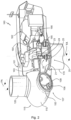
- Figure 1 illustrates a perspective view of one example of a wind turbine 160.
- the wind turbine 160 includes a tower 170 extending from a support surface 150, a nacelle 161 mounted on the tower 170, and a rotor 115 coupled to the nacelle 161.
- the rotor 115 includes a rotatable hub 110 and at least one rotor blade 120 coupled to and extending outwardly from the hub 110.
- the rotor 115 includes three rotor blades 120.
- the rotor 115 may include more or less than three rotor blades 120.
- Each rotor blade 120 may be spaced about the hub 110 to facilitate rotating the rotor 115 to enable kinetic energy to be transferred from the wind into usable mechanical energy, and subsequently, electrical energy.
- the hub 110 may be rotatably coupled to an electric generator 162 ( figure 2 ) positioned within the nacelle 161 to permit electrical energy to be produced.
- FIG 2 illustrates a simplified, internal view of one example of the nacelle 161 of the wind turbine 160 of figure 1 .
- the generator 162 may be disposed within the nacelle 161.
- the generator 162 may be coupled to the rotor 115 of the wind turbine 160 for generating electrical power from the rotational energy generated by the rotor 115.
- the rotor 115 may include a main rotor shaft 163 coupled to the hub 110 for rotation therewith.
- the generator 162 may then be coupled to the rotor shaft 163 such that rotation of the rotor shaft 163 drives the generator 162.
- the generator 162 includes a generator shaft 166 rotatably coupled to the rotor shaft 163 through a gearbox 164.
- rotor shaft 163, gearbox 164, and generator 162 may generally be supported within the nacelle 161 by a support frame or bedplate 165 positioned atop the wind turbine tower 170.
- the nacelle 161 may be rotatably coupled to the tower 170 through a yaw system 20 in such a way that the nacelle 161 is able to rotate about a yaw axis YA, or there may be other ways to position the rotor in the desired angle to the wind. If there is a yaw system 20, such system will usually comprise a yaw bearing having two bearing components configured to rotate with respect to the other.
- the tower 170 is coupled to one of the bearing components and the bedplate or support frame 165 of the nacelle 161 is coupled to the other bearing component.
- the yaw system 20 comprises an annular gear 21 and a plurality of yaw drives 22 with a motor 23, a gearbox 24 and a pinion 25 for meshing with the annular gear 21 for rotating one of the bearing components with respect to the other.
- the tool comprises a first wheeled platform, a second wheeled platform and a frame.
- the frame has a first side portion, and a second side portion.
- the first side portion of the frame is attached to the first wheeled platform and is configured to support a first end portion of a sling.
- the second side portion of the frame is attached to the second wheeled platform and is configured to support a second end portion of the sling.
- the first and second wheeled platforms are separated along a frame horizontal direction such that the tower section can be supported on the sling at least partially between the first and second side portions of the frame.
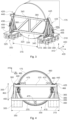
- Figure 3 shows a perspective view of a tool 300 and a wind turbine tower section 175 supported by the tool 300.
- Figure 4 shows a front view of another tool 300 supporting a wind turbine tower section 175.
- the tool 300 comprises a first wheeled platform 305 and a second wheeled platform 310.
- the first 305 and second 310 wheeled platforms are separated a distance 315.
- the tool 300 also comprises a frame 320.
- the frame 320 includes a first side portion 325, a second side portion 330 and a central portion 335.
- the central portion 335 connects the first and second side portions and may bridge a gap between the two wheeled platforms.
- the frame 320 also has a top portion 340 and a bottom portion 345.
- the frame 320 separates the first 305 and second 310 wheeled platforms along a substantially horizontal direction 405.
- the frame 320 also extends along a vertical direction 410.
- the tool 300 may move over the ground along a transportation direction 400.
- Direction 405 may also be called a lateral horizontal direction and direction 410 may be called vertical direction 410.
- the frame 320 may be longer along a horizontal direction 405 than along a frame vertical direction 410, as in the examples of figures 3 and 4 . In other words, the frame may be longer than it is high.
- a length 350 of the frame 320 may for example be between 5 and 15 meters and a height 355 of the frame may for example be between be between 5 and 15 meters, and a width of the frame 320 may be between 2 and 6 meters.
- the frame 320 may be longer in a vertical direction 310 and thus a length of the frame 320 may extend along a vertical direction 310 instead of a lateral horizontal direction 405.
- the first 305 and second 310 platforms may have a distance between them of 4 - 13 meters in some examples.
- Each of the wheeled platforms may comprise a substantially flatbed base and a plurality of wheels, e.g. between 8 and 20 wheels. Sets of wheels may be arranged on common axels. Each of the wheeled platforms may comprise an independent propulsion mechanism. The wheeled platforms may be SPMTs.
- the first side portion of the frame 325 is attached to the first wheeled platform 305 and the second side portion of the frame 330 is attached to the second wheeled platform 310. Attachment may be for instance be by nuts and bolts.
- the frame first 325 and second 330 side portions may extend in a vertical direction 410.
- the first side portion of the frame 325 may include a first substantially vertical beam 360.
- the second side portion of the frame 330 may include a second substantially vertical beam 365.
- the first side portion of the frame 325 may comprise one or more inclined additional beams or struts 385.
- the second first side portion of the frame 330 may comprise one or more inclined additional beams or struts 385.
- An inclined additional beam 385 may extend from an upper (see figure 3 ) or a middle portion (see figure 4 ) of the first vertical beam 360 to the first wheeled platform 305 or to a base beam 390.
- One or more of the additional base beams 390 may extend in a direction substantially parallel to the lateral horizontal direction 405, as in figures 3 and 4 .
- One or more of the additional base beams 390 may extend in a direction substantially parallel to the transport horizontal direction 400, as in figure 3 .
- One or more additional base beams 390 may extend in any other direction.
- the additional beams 385, 390 may help to stabilize and reinforce the frame first 325 and second 330 side portions.
- the first 325 and second 330 side portions of the frame are configured to support first 420 and second 425 end portions of a sling 415, respectively.
- An end portion of a sling 420, 425 may be understood as a portion of a sling 415 close to an end 430, 435 of the sling 415.
- An end 430, 435 of a sling 415 may be included in and end portion 420, 425 of a sling 415.
- the first side portion of the frame 325 may comprise suitable sling attachments.
- the first side portion of the frame 325 may comprise one or more first sling attachment points 450 for attaching a first end 430 of the sling 415
- the second side portion of the frame 330 may comprise one or more second attachment points 455 for attaching the second end 435 of the sling 415.
- One or more sling attachment points 450, 455 may be D-rings, as shown in figure 4 .
- Having several sling attachment points 450, 455 at different heights in a side portion 325, 330 of the frame enables adjusting a sling 415 and the extent to which the sling hangs between the side portions 325, 330 of the frame. Therefore, with a single tool 300, tower sections 175 of different diameters may be transported.
- the first side portion 325 of the frame 320 may comprise a sling top guide 440; and the second side portion 330 of the frame 320, for example a vertical beam 365, may comprise a second top guide 445.
- the first 440 and second 445 top guides are configured to support a sling 415.
- One or more sling attachment points 450, 455 and a top 440, 450 of the first 325 and second 330 side portions of the frame which supports and redirects the sling may be in a plane that includes the vertical 410 and the lateral horizontal 405 directions. This may help to stabilize and better support a tower section 175.
- sling attachment points 450, 455 are provided in an inclined additional beam 385.
- sling attachment points 450, 455 may be provided in other places of the frame side portions 325, 330.
- they could be provided in a vertical beam 360, 365 of the frame side portions 325, 330.
- Sling attachment points 450, 455 may be also provided on the first 305 and/or second 310 wheeled platforms.
- Sling attachments may be provided relatively close to a base of the wheeled platforms.
- the sling ends may extend from the attachment points over a top 440, 445 of the first and second frame side portions 325, 330.
- the central portion of the frame 335 may include a truss structure having one or more beams connecting the frame first 320 and second 330 side portions.
- the central portion of the frame 335 may comprise a top lateral beam 370 and a bottom lateral beam 375. These beams 370, 375 may extend in a lateral horizontal direction 405. These beams 370, 375 may be bolted to vertical beams 360 and 365.
- the truss structure of the central portion of the frame 335 may include vertical members or beams and diagonal members of beams 380.
- central inclined beams 380 connect lateral horizontal beams 370 and 375.
- one or more central inclined beams 380 may connect the frame first 325 and second 220 side portions.
- Central inclined beams 380 may be present in addition to or as an alternative to lateral horizontal beams 370, 375.
- a central top beam 370 may not lie exactly above a central bottom beam 375 in figures 3 and 4 .
- Such beam 370 may be displaced in a transport horizontal direction 400 and away from the sling attachment points 450, 455 for permitting a sling 115 to hang in a plane formed by the vertical 410 and lateral horizontal 405 directions.
- a central top beam 370 may limit the displacement of a tower section 175 when supported by a sling 115 and may therefore help to stabilize the tower section 174 during transportation.
- Diagonal beams 380 may have different inclination angles with respect to a lateral horizontal direction 405, for example each inclined beam 380 may have an inclination of 30o, or 45°, or 60°. Inclined beams 380 may also have different inclination angles than other inclined beams 380. For example, an inclined beam 380 may have an angle of 45o with respect to the lateral horizontal direction 405 and another inclined beam may have an angle of 125o with respect to direction 405.
- a frame 320 may in some examples be made of steel.
- a frame 320 may be integrally formed of a single piece or may comprise two or more pieces or beams joined to each other.
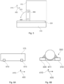
- Figure 5 schematically illustrates a lateral view of a tool 300.
- the tool 300 may include hinges 460, 461, 465, 466.
- the first side portion of the frame 325 may include at least a first hinge 460, 461 and the second side portion of the frame 330 may include at least a second hinge 465, 466 for rotating the frame 320 or a portion of the frame 320 about an axis substantially parallel to a frame horizontal direction 405.
- arrow 470 indicates the movement of the frame 320 or a portion of the frame 320 when rotation about an axis in the lateral horizontal direction 405 occurs.
- Hinges may be provided at a bottom of the first 325 and second 330 side portions of the frame. Additionally or alternatively, hinges may be provided at a top of the first 325 and second 330 side portions of the frame. For example, one or more hinges may be provided per vertical beam 360, 365 of a side portion 325, 550 of the frame 320.
- Figures 4 and 5 schematically show two hinges per side portion of the frame.
- the first side portion of the frame 325 in particular the first vertical beam 360, includes a top hinge 461 and a bottom hinge 460.
- the second side portion of the frame 330 in particular the second vertical beam 365, includes a top hinge 466 and a bottom hinge 465.
- the bottom hinges 460, 465 may be used to start to rotate a tower portion 175 at the beginning of the upending process whereas the top hinges 461, 466 may be used to rotate the tower portion 175 subsequently, towards the end of the upending process. In some other examples, only top hinges 461, 466 may be used to rotate a tower portion 175 during upending.
- the tool 300 may comprise a sling 415 having a first end 430 configured to be attached to the first side portion of the frame 325 and a second end 435 configured to be attached to the second side portion of the frame 330, the sling 415 being configured to support a tower section 175.
- Figures 3 and 4 show the tool 300 including a sling 415.
- a first end 430 of a sling 415 may be attached to a first sling attachment point 450, and a second opposite end 435 of the sling 415 may be attached to a second sling attachment point 455.
- a first end portion 420 of the sling 415 may pass over a top guide 440 of the first side portion 325 of the frame 320, and a second end portion 425 of the sling 415 may pass over a top guide 445 of the second side portion 330 of the frame 330, supporting and redirecting the sling.
- An end 430, 435 of a sling 415 may include an eye which may be attached to e.g. a D-ring by a shackle.
- the sling 415 may therefore hang between the frame first 325 and second 330 side portions.
- the sling 415 may also hang between the first 305 and second 310 wheeled platforms. Attaching the sling 415 in higher or lower attachment points 450, 455 of a frame side portion 325, 330 enables to let a sling 415 to hang more or less, i.e. be closer or further away from the ground.
- a sling 415 may have a length between 10 and 60 m.
- a sling 415 may be flat.
- a sling 415 may be made of polyester or nylon.
- a sling may be made of leather or metal such as steel.
- a tool 300 may comprise one or more tower section flange clamps 475.
- these clamps 475 may be attached to the frame 320, for example to a central portion 335 of the frame 320, and they may be retractable.
- the fasteners 475 may be moved towards the tower section for securing it.
- two clamps may move in a lateral horizontal direction 405 and one may move in a vertical direction 410.
- a tower section flange clamp 475 may clamp or grip an interior surface of the tower section 175. Stability of the tower section 175 may be enhanced.
- clamps 475 may only be used for securing the tower section 185 when upending.
- figure 4 also shows two lifting lugs 483 to which a lifting device, e.g. a main crane (see figure 6E ), may be attached.
- a lifting device e.g. a main crane (see figure 6E ).
- a further aspect of the invention provides a method 500 for handling a wind turbine tower section 170.
- the method 500 may use two tools 300 according to any of the examples described above.
- Handling may include specifically transporting and upending a tower section. Handling may also include picking, lifting, and/or storing a tower section.
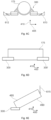
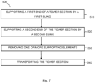
- Figures 6A to 6E schematically show some details of the method.
- the orientation of a wind turbine tower section 175 and one or more tools 300 is indicated by direction arrows 400, 405 and 410.
- 400 corresponds to a longitudinal direction of the tower section.
- 405 corresponds to a transverse or width direction of the tower section.
- 410 corresponds to a vertical direction.
- the method comprises, at step 510, supporting a first end of a tower section 175 placed on one or more supports 610 for storage by a first sling 415 hanging between a first side portion of the frame 325 attached to a first wheeled platform 305 and a second side portion of the frame 330 attached to a second wheeled platform 310 of a tool 300.
- the supports 610 may be supporting elements configured particularly for storage.
- a tower section 175 may be placed on supports 610, for example on two cradles.
- a first tool 300 with a sling 415 may approach a first end of the tower section 175 such that the first end of the tower section 175 lies between a first 325 and second 330 side portions of the frame 320 of the tool 300.
- FIG 6B This is schematically illustrated in figure 6B and may also be seen in figures 3 and 4 .
- a sling 415 may lift, e.g. slightly lift, the first end of the tower section 175. This may be performed by adjusting a distance of the platform of the first wheeled platform 305 to the ground. For example, the platform may be hydraulically adjusted in a vertical direction 410 to lift a first tower section end.
- the first wheeled platform 305 may be a self-propelled modular transport (SPMT).
- SPMT self-propelled modular transport
- the sling 415 may adapt to a contour of the tower section end, as illustrated e.g. in figure 6B . Alternatively, lifting may occur by stretching or pulling the sling.
- the method further comprises, at step 520, supporting a second end of the tower section 175 by a second sling 415 hanging between a first side portion of the frame 325 attached to a first wheeled platform 305 and a second side portion of the frame 330 attached to a second wheeled platform 310 of a second tool 300.
- the second end of the wind turbine portion 175 may be supported in a same manner as the first end of the wind turbine portion 175.
- the tool frame 320 in particular a central portion 336 of the frame 320, may be in direct contact with a portion of a tower section flange 480 (see figure 4 ). This may limit the movement of the tower section 175 in a transport horizontal direction 400 and therefore help to stabilize the tower section 175 during its transport.
- the method further comprises, at block 530, removing the one or more storage supporting elements 610. As the supporting elements are no longer needed for supporting the tower section 175, they may be moved from below the tower section 175.
- a supporting element 610 is a cradle 611
- removing a cradle may comprise separating the cradle 611 into two portions. This is schematically illustrated in figure 6C .
- a cradle 611 may comprise a first portion 612, e.g. a first half of the cradle, and a second portion 613, e.g. a second half of the cradle, joined to one another e.g. by a pin.
- Each cradle portion 612, 613 may be removed e.g. by a forklift moving in a lateral horizontal direction 405.
- the method 500 may further comprise, at block 540, transporting the tower section 175. Now that two tools 300 are supporting the tower section 175 and that the supports 610 where it was stored are not in the way of the tool 300, the first 305 and second 310 wheeled platforms of the first tool 300 and the first 305 and second 310 wheeled platforms of the second tool 300 may move the tower section 175.
- the movement may for example be in a transport direction 400, although movement in any other horizontal direction (i.e. in the plane formed by directions 400 and 405) is possible.
- Figure 6D schematically represents a tower section 175 being carried by two tools 300, 300' in a transport direction 400.
- tools 300, 300' may facilitate and make the handling and transport of a wind turbine tower section 175 more efficient.
- the method 500 may further comprise upending the tower section 175 by lifting one tower section end while the other tower section end is supported by the tool 300.
- Figure 6E schematically illustrates such a situation.
- a lifting device e.g. a crane.
- the tool previously supporting that end may or may not be removed.
- a line 615 e.g. of a crane, is lifting the tower section end which will remain on top after upending.
- Tool 300 may enable upending of a tower section 175 in a more stable and controlled manner than when using e.g. a tail crane and a main crane.
- Upending may comprise in some examples rotating the first 325 and second 330 side portions of the frame of the tool 300 supporting one end of the tower section about an axis substantially parallel to a horizontal direction 405.
- the tool 300 may help to put the tower section 175 in, or close to, a vertical position (see figures 5 and 6D ).
- One or more hinges 460, 461, 465, 466 per side of the frame 325, 330 may be used. This may also facilitate upending of the tower section in comparison to when a tail crane and a main crane are used.
- the method may further comprise securing a tower section to be placed at the bottom by clamping a flange 480 of a tower section.
- Clamps 475 or other gripping elements may be extendable and retractable from the tool 300, e.g. from a frame center portion 335 of the tool 300 (see figure 4 ). At least an interior surface of the tower section 175 may be clamped before the other tower end portion is lifted for upending.
- tool 300 may include one or more fasteners 475 which may clamp a bottom 485 of the tower section 175 in figure 6 before line 615 lifts, or even before line is attached to, a top 490 of the tower section 175. Control and stabilization of the tower section may be enhanced by using the clamps 475.
- the method may further comprise transferring the tower section 175 to a vessel for further transport. This step may be performed if, for example, the tower section 175 is manufactured or stored at a certain place and it has to be transported over the sea to an installation or upending site. In some examples, the tower section 175 may be lifted from the tools 300, 300' to do so.
- the tower section 175 may be positioned as in figure 6D , and one or more lifting devices, e.g. two cranes, may lift it. In some examples, two slings may be used to hoist the tower section. The tower section 175 may then be positioned and secured on a boat, e.g. it may be attached to a vessel deck.
- one or more lifting devices e.g. two cranes
- two slings may be used to hoist the tower section.
- the tower section 175 may then be positioned and secured on a boat, e.g. it may be attached to a vessel deck.
- one or more supporting elements 610 may be attached to the tower section before placing it on the vessel, e.g. while supported by tools 300, 300' and before lifting it.
- One or more cradles 611 e.g. two cradles, may be secured, e.g. bolted, to the tower section 175 before lifting it and placing it on a vessel deck.
- the tower section 175 may be alternatively placed on one or more supporting elements 610 attached to a vessel.
- One or more cradles 611 may be e.g welded to the vessel deck, and the tower section may be placed on the cradles 611. Additional fastening of the tower section 175 to the vessel deck may be provided independently of whether the tower section supporting means 610 are attached to it or to a vessel.
- RoRo roll-on/roll-off
- the tower section 175 may be carried into the vessel by the tools 300, 300', without the need of lifting devices and lifting lines 615.
- the tower section(s) may first be transported to a logistical hub for later transportation to individual sites. If the tower section 175 is to be upended onshore, the method may further comprise taking the tower section out of the vessel and transporting it on two tools 300, 300'.
- the tower section 175 may be lifted to take it out of the vessel.
- the tower section 175 may in some examples first be placed on one or more supports 610 for temporary storage and then picked up by two tools 300, 300' as already explained with respect to figures 6A to 6D .
- the tower may then be carried to an installation site and may be upended as explained with respect to figure 6E .
- the two tools 300, 300' may likewise move it out of the vessel.
- the tower section 175 may be transported offshore and it is placed on supporting elements 610 on the vessel, it may be lifted from the vessel deck by one or more lifting devices, such as cranes. In this case attaching the supporting elements 610 to the vessel may be ease the process with respect to attaching them to the tower section 175.
- the tower section 175 may be upended as explained with respect to figure 6E .
- the tool 300 comprises a first base 305 and a second base 310 configured to move on a ground.
- the tool 300 further comprises a frame 320 extending between the first 305 and the second 310 bases, a first frame side 325 being supported by the first base 305 and a second opposite frame side 330 being supported by the second base 330.
- the first and second bases are arranged substantially parallel to each other in such a way that a tower section can be supported by the frame between the first and second bases.
- the frame 320 may be configured for permitting a sling 415 attached to the tool 300 to hang between the first 305 and second 310 frame sides.
- the first 305 and second 310 bases may have a substantially flat upper portion mounted to moving elements such as wheels.
- Each of the first 305 and second 310 bases may be an SPMT any may have suitable driving or propulsion systems.
- the frame 320 may include a plurality of beams and may be made of steel.
- the frame 320 may be bolted to the first 305 and second 310 movable bases.
- a sling 415 configured to support an end tower section 175 may be attached to the tool 300.
- An end 430 of the sling 415 may be attached to the first frame side 325 and the other end 435 of the sling 415 may be attached to the second frame side 330. Additionally or alternatively, a first sling end 430 may be attached to the first base 305 and the opposite end 435 of the sling 415 may be attached to the second base 310.
- the first frame side 325 may comprise two or more sling fasteners 450 at different heights and the second frame side 330 may comprise two or more sling fasteners 455 at different heights.
- the sling 415 may hang between the frame first 325 and second 330 sides, and optionally also between the first 305 and second movable bases.
- first frame side 325 may comprise at least a first hinge 460, 461 and the second frame side 330 may comprise at least a second hinge 465 for rotating the frame about a substantially horizontal axis 405.
- the frame 320 may comprise one or more retractable clamping devices 475 for fixing a wind turbine tower section flange 480 to the tool 300.
- the explanation provided with respect to figures 3 to 5 may generally be applicable to this tool. Similarly, such a tool may also be used in a method 500 as described above.
Landscapes
- Engineering & Computer Science (AREA)
- Mechanical Engineering (AREA)
- Chemical & Material Sciences (AREA)
- Combustion & Propulsion (AREA)
- Sustainable Energy (AREA)
- Life Sciences & Earth Sciences (AREA)
- Sustainable Development (AREA)
- General Engineering & Computer Science (AREA)
- Transportation (AREA)
- Health & Medical Sciences (AREA)
- Public Health (AREA)
- Wind Motors (AREA)
- Ocean & Marine Engineering (AREA)
- Vaporization, Distillation, Condensation, Sublimation, And Cold Traps (AREA)
Claims (15)
- Ein Werkzeug (300) zum Handhaben eines Turmabschnitts (175) eines Windturbinenturms (170), wobei das Werkzeug umfasst:eine erste Plattform mit Rädern (305);eine zweite Plattform mit Rädern (310);einen Rahmen (320) mit einem ersten Seitenteil (325) und einem zweiten Seitenteil (330);wobei der erste Seitenabschnitt des Rahmens (325) an der ersten mit Rädern versehenen Plattform (305) befestigt ist und konfiguriert ist um einen ersten Endabschnitt (420) einer Schlinge (415) zu tragen;wobei der zweite Seitenabschnitt des Rahmens (330) an der zweiten mit Rädern versehenen Plattform (310) befestigt ist und konfiguriert ist um einen zweiten Endabschnitt (425) der Schlinge (415) zu tragen;die erste (305) und die zweite (310) Plattform mit Rädern entlang einer im Wesentlichen horizontalen Richtung (405) getrennt (315) sind, so dass ein Turmabschnitt (175) zumindest teilweise zwischen der ersten (325) und der zweiten Seite (330) des Rahmens auf dem Anschlagmittel (415) abgestützt werden kann; undwobei der erste Seitenabschnitt des Rahmens (325) ein erstes Scharnier (461) und der zweite Seitenabschnitt des Rahmens (330) ein zweites Scharnier (466) zum Drehen des Rahmens oder eines Teils des Rahmens um eine im Wesentlichen horizontale Achse aufweist.
- Werkzeug nach Anspruch 1, wobei der erste Seitenabschnitt des Rahmens (325) ein oberes Scharnier (461) und ein unteres Scharnier (460) und der zweite Seitenabschnitt des Rahmens (330) ein oberes Scharnier (466) und ein unteres Scharnier (465) aufweist.
- Werkzeug nach einem der Ansprüche 1 bis 2, wobei der erste Seitenabschnitt des Rahmens (325) einen oder mehrere erste Schlingenbefestigungspunkte (450) zum Befestigen eines ersten Endes der Schlinge (430) und der zweite Seitenabschnitt des Rahmens (330) einen oder mehrere zweite Schlingenbefestigungspunkte (455) zum Befestigen eines zweiten Endes der Schlinge (435) aufweist.
- Werkzeug nach einem der Ansprüche 1 bis 3, wobei der erste Seitenabschnitt des Rahmens (325) eine erste obere Führung (440) und der zweite Seitenabschnitt des Rahmens (330) eine zweite obere Führung (445) aufweist, wobei die erste (440) und die zweite (445) obere Führung so gestaltet sind, dass sie die Schlinge (415) tragen.
- Werkzeug nach einem der Ansprüche 1 bis 4, ferner umfassend eine Schlinge (415) mit einem ersten Ende (430), das so konfiguriert ist, dass es an dem ersten Seitenabschnitt des Rahmens (325) befestigt werden kann, und einem zweiten Ende (435), das so konfiguriert ist, dass es an dem zweiten Seitenabschnitt des Rahmens (330) befestigt werden kann, wobei die Schlinge (415) so konfiguriert ist, dass sie einen Turmabschnitt (175) trägt.
- Das Werkzeug nach Anspruch 5, wobei die Schlinge (415) eine Flachschlinge ist.
- Das Werkzeug nach einem der vorhergehenden Ansprüche, das außerdem eine oder mehrere Klemmen (475) zum Festklemmen eines Turmabschnittflansches (480) umfasst.
- Verfahren (500) zur Handhabung eines Windturbinenturmabschnitts (175), wobei das Verfahren umfasst:Stützen (510) eines ersten Endes eines Turmabschnitts, der zuvor auf einer oder mehreren Stützen (610) in einer ersten Schlinge platziert wurde, die zwischen , einem ersten Seitenabschnitt eines Rahmens, der an einer ersten mit Rädern versehenen Plattform befestigt ist, und einem zweiten Seitenabschnitt des Rahmens, der an einer zweiten mit Rädern versehenen Plattform eines ersten Werkzeugs (300) befestigt ist, hängt, nach einem der Ansprüche 1 bis 7;Stützen (520) eines zweiten Endes des Turmabschnitts in einer zweiten Schlinge, die zwischen einem ersten Seitenabschnitt eines Rahmens, der an einer ersten mit Rädern versehenen Plattform befestigt ist, und einem zweiten Seitenabschnitt des Rahmens, der an einer zweiten mit Rädern versehenen Plattform eines zweiten Werkzeugs (300') nach einem der Ansprüche 1 bis 7 befestigt ist, hängt; undEntfernen (530) der einen oder mehreren Stützen (610).
- Das Verfahren nach Anspruch 8, das ferner das Transportieren (540) des Turmteils (175) umfasst.
- Verfahren nach Anspruch 8 oder 9, das ferner das Aufrichten des Turmabschnitts (175) durch Anheben eines zweiten Endes des Turmabschnitts (490) umfasst, während das erste Ende des Turmabschnitts (485) von dem ersten Werkzeug (300) getragen wird.
- Verfahren nach Anspruch 10, wobei das Aufrichten das Drehen des ersten und des zweiten Rahmenseitenteils des ersten Werkzeugs um eine im Wesentlichen horizontale Achse (405) umfasst.
- Verfahren nach Anspruch 11, das ferner das Sichern eines ersten Endes des darunter zu platzierenden Turmabschnitts (485) durch Festklemmen eines Turmabschnittflansches (480) umfasst.
- Verfahren nach einem der Ansprüche 8 bis 12, wobei eine oder mehrere der Stützen (610) Wiegen (511) sind und das Entfernen einer Wiege das Trennen der Wiege in zwei Teile (612, 613) umfasst.
- Verfahren nach einem der Ansprüche 8 bis 13, wobei der Turmabschnitt zum Weitertransport in ein Schiff umgeladen wird.
- Verfahren nach Anspruch 14, bei dem der Turmabschnitt auf einem oder mehreren an dem Behälter befestigten Turmabschnittstützelementen angeordnet ist.
Priority Applications (6)
| Application Number | Priority Date | Filing Date | Title |
|---|---|---|---|
| PL21382192.9T PL4056842T3 (pl) | 2021-03-09 | 2021-03-09 | Narzędzia oraz sposoby przenoszenia sekcji wież |
| EP21382192.9A EP4056842B1 (de) | 2021-03-09 | 2021-03-09 | Werkzeuge und verfahren zur handhabung von turmabschnitten |
| JP2022018387A JP2022138117A (ja) | 2021-03-09 | 2022-02-09 | タワーセクションのハンドリングのためのツールおよび方法 |
| KR1020220028758A KR20220126651A (ko) | 2021-03-09 | 2022-03-07 | 타워 섹션을 취급하기 위한 도구 및 방법 |
| US17/689,247 US20220289098A1 (en) | 2021-03-09 | 2022-03-08 | Tools and methods for handling tower sections |
| CN202210229051.6A CN115045802A (zh) | 2021-03-09 | 2022-03-09 | 用于操纵塔架区段的工具和方法 |
Applications Claiming Priority (1)
| Application Number | Priority Date | Filing Date | Title |
|---|---|---|---|
| EP21382192.9A EP4056842B1 (de) | 2021-03-09 | 2021-03-09 | Werkzeuge und verfahren zur handhabung von turmabschnitten |
Publications (2)
| Publication Number | Publication Date |
|---|---|
| EP4056842A1 EP4056842A1 (de) | 2022-09-14 |
| EP4056842B1 true EP4056842B1 (de) | 2023-10-11 |
Family
ID=75223262
Family Applications (1)
| Application Number | Title | Priority Date | Filing Date |
|---|---|---|---|
| EP21382192.9A Active EP4056842B1 (de) | 2021-03-09 | 2021-03-09 | Werkzeuge und verfahren zur handhabung von turmabschnitten |
Country Status (6)
| Country | Link |
|---|---|
| US (1) | US20220289098A1 (de) |
| EP (1) | EP4056842B1 (de) |
| JP (1) | JP2022138117A (de) |
| KR (1) | KR20220126651A (de) |
| CN (1) | CN115045802A (de) |
| PL (1) | PL4056842T3 (de) |
Families Citing this family (1)
| Publication number | Priority date | Publication date | Assignee | Title |
|---|---|---|---|---|
| EP3736442A1 (de) * | 2019-05-06 | 2020-11-11 | Siemens Gamesa Renewable Energy A/S | Werkzeuganordnung zum entladen eines turms oder eines turmsegments von einem transportfahrzeug und/oder zum lagern des turms oder des turmsegments |
Family Cites Families (4)
| Publication number | Priority date | Publication date | Assignee | Title |
|---|---|---|---|---|
| EP2666669B1 (de) * | 2012-05-22 | 2016-06-29 | Siemens Aktiengesellschaft | Transport von Windturbinenschaufeln, insbesondere entlang kurviger Straßen |
| DK3090171T3 (da) * | 2013-12-30 | 2020-01-27 | Vestas Wind Sys As | Forbedringer relateret til komponenthåndtering, særligt vindmøllekomponenthåndtering |
| DE202016100449U1 (de) * | 2016-01-29 | 2017-05-04 | Nordex Energy Gmbh | Haltevorrichtung für ein Windenergieanlagenrotorblatt |
| CN110758224A (zh) * | 2019-10-28 | 2020-02-07 | 安徽兴宇轨道装备有限公司 | 一种轮胎式隧道管廊运架车 |
-
2021
- 2021-03-09 EP EP21382192.9A patent/EP4056842B1/de active Active
- 2021-03-09 PL PL21382192.9T patent/PL4056842T3/pl unknown
-
2022
- 2022-02-09 JP JP2022018387A patent/JP2022138117A/ja active Pending
- 2022-03-07 KR KR1020220028758A patent/KR20220126651A/ko unknown
- 2022-03-08 US US17/689,247 patent/US20220289098A1/en active Pending
- 2022-03-09 CN CN202210229051.6A patent/CN115045802A/zh active Pending
Also Published As
| Publication number | Publication date |
|---|---|
| PL4056842T3 (pl) | 2024-02-26 |
| JP2022138117A (ja) | 2022-09-22 |
| EP4056842A1 (de) | 2022-09-14 |
| CN115045802A (zh) | 2022-09-13 |
| KR20220126651A (ko) | 2022-09-16 |
| US20220289098A1 (en) | 2022-09-15 |
Similar Documents
| Publication | Publication Date | Title |
|---|---|---|
| EP3504149B1 (de) | Verfahren und vorrichtung zur durchführung von wartungsarbeiten an einer windturbinenkomponente | |
| EP2275340B1 (de) | Offshore-Windturbineninstallation | |
| EP1843964B1 (de) | Hubvorrichtung für einen windturbinengenerator | |
| EP2433001B1 (de) | Nabe für eine windturbine | |
| US20100139062A1 (en) | Lowering and raising a single wind turbine rotor blade from six-o'clock position | |
| WO2013051167A1 (en) | Blade attaching and detaching device and method for wind turbine generator | |
| CN101878178A (zh) | 在站点建立风力涡轮机的方法、风力涡轮机塔的运输、风力涡轮机塔和适合运输风力涡轮机塔的船 | |
| KR102239542B1 (ko) | 해상 풍력 발전기 설치 방법 | |
| WO2011134472A1 (en) | Handling of a crane for use in installation and service of wind turbine generator components | |
| US11560875B2 (en) | Method for assembling a wind turbine | |
| WO2013095136A1 (en) | Method for installing an offshore wind turbine, installation barge for installing an offshore wind turbine | |
| US20220289098A1 (en) | Tools and methods for handling tower sections | |
| US20190271298A1 (en) | Rotor blade assembly | |
| US8845248B2 (en) | Transport structure and methods for transporting and/or lifting a large scale generator | |
| EP4295039A1 (de) | Verfahren und schaufelinstallationsvorrichtung zur installation einer schaufel einer offshore-windturbine | |
| US20220260057A1 (en) | Installation system and method of upending and installing a wind turbine tower | |
| CN116635295A (zh) | 组装并安装风力涡轮机 | |
| CN113446165A (zh) | 风力涡轮机部件运输装置 | |
| NL2032193B1 (en) | Method and blade installation device for installing a blade of an offshore wind turbine | |
| EP2682596B1 (de) | Transportvorrichtung für einen Windturbinenrotor, Transportsystem und Verfahren zum Transportieren von mindestens zwei Rotoren | |
| US20240133364A1 (en) | Method and blade installation device for installing a blade of an offshore wind turbine | |
| US20230392583A1 (en) | Assembling and installing a wind turbine |
Legal Events
| Date | Code | Title | Description |
|---|---|---|---|
| PUAI | Public reference made under article 153(3) epc to a published international application that has entered the european phase |
Free format text: ORIGINAL CODE: 0009012 |
|
| STAA | Information on the status of an ep patent application or granted ep patent |
Free format text: STATUS: THE APPLICATION HAS BEEN PUBLISHED |
|
| AK | Designated contracting states |
Kind code of ref document: A1 Designated state(s): AL AT BE BG CH CY CZ DE DK EE ES FI FR GB GR HR HU IE IS IT LI LT LU LV MC MK MT NL NO PL PT RO RS SE SI SK SM TR |
|
| STAA | Information on the status of an ep patent application or granted ep patent |
Free format text: STATUS: REQUEST FOR EXAMINATION WAS MADE |
|
| 17P | Request for examination filed |
Effective date: 20230314 |
|
| RBV | Designated contracting states (corrected) |
Designated state(s): AL AT BE BG CH CY CZ DE DK EE ES FI FR GB GR HR HU IE IS IT LI LT LU LV MC MK MT NL NO PL PT RO RS SE SI SK SM TR |
|
| P01 | Opt-out of the competence of the unified patent court (upc) registered |
Effective date: 20230529 |
|
| GRAP | Despatch of communication of intention to grant a patent |
Free format text: ORIGINAL CODE: EPIDOSNIGR1 |
|
| STAA | Information on the status of an ep patent application or granted ep patent |
Free format text: STATUS: GRANT OF PATENT IS INTENDED |
|
| INTG | Intention to grant announced |
Effective date: 20230720 |
|
| RIC1 | Information provided on ipc code assigned before grant |
Ipc: F03D 13/20 20160101ALI20230707BHEP Ipc: B61D 3/16 20060101ALI20230707BHEP Ipc: B60P 3/40 20060101ALI20230707BHEP Ipc: F03D 13/40 20160101AFI20230707BHEP |
|
| GRAS | Grant fee paid |
Free format text: ORIGINAL CODE: EPIDOSNIGR3 |
|
| GRAA | (expected) grant |
Free format text: ORIGINAL CODE: 0009210 |
|
| STAA | Information on the status of an ep patent application or granted ep patent |
Free format text: STATUS: THE PATENT HAS BEEN GRANTED |
|
| AK | Designated contracting states |
Kind code of ref document: B1 Designated state(s): AL AT BE BG CH CY CZ DE DK EE ES FI FR GB GR HR HU IE IS IT LI LT LU LV MC MK MT NL NO PL PT RO RS SE SI SK SM TR |
|
| REG | Reference to a national code |
Ref country code: GB Ref legal event code: FG4D |
|
| REG | Reference to a national code |
Ref country code: CH Ref legal event code: EP |
|
| REG | Reference to a national code |
Ref country code: DE Ref legal event code: R096 Ref document number: 602021005824 Country of ref document: DE |
|
| REG | Reference to a national code |
Ref country code: IE Ref legal event code: FG4D |
|
| REG | Reference to a national code |
Ref country code: NL Ref legal event code: FP |
|
| REG | Reference to a national code |
Ref country code: LT Ref legal event code: MG9D |
|
| REG | Reference to a national code |
Ref country code: AT Ref legal event code: MK05 Ref document number: 1620451 Country of ref document: AT Kind code of ref document: T Effective date: 20231011 |
|
| PG25 | Lapsed in a contracting state [announced via postgrant information from national office to epo] |
Ref country code: GR Free format text: LAPSE BECAUSE OF FAILURE TO SUBMIT A TRANSLATION OF THE DESCRIPTION OR TO PAY THE FEE WITHIN THE PRESCRIBED TIME-LIMIT Effective date: 20240112 |
|
| PG25 | Lapsed in a contracting state [announced via postgrant information from national office to epo] |
Ref country code: IS Free format text: LAPSE BECAUSE OF FAILURE TO SUBMIT A TRANSLATION OF THE DESCRIPTION OR TO PAY THE FEE WITHIN THE PRESCRIBED TIME-LIMIT Effective date: 20240211 |
|
| PG25 | Lapsed in a contracting state [announced via postgrant information from national office to epo] |
Ref country code: LT Free format text: LAPSE BECAUSE OF FAILURE TO SUBMIT A TRANSLATION OF THE DESCRIPTION OR TO PAY THE FEE WITHIN THE PRESCRIBED TIME-LIMIT Effective date: 20231011 |
|
| PGFP | Annual fee paid to national office [announced via postgrant information from national office to epo] |
Ref country code: IE Payment date: 20240222 Year of fee payment: 4 Ref country code: NL Payment date: 20240220 Year of fee payment: 4 |
|
| PG25 | Lapsed in a contracting state [announced via postgrant information from national office to epo] |
Ref country code: AT Free format text: LAPSE BECAUSE OF FAILURE TO SUBMIT A TRANSLATION OF THE DESCRIPTION OR TO PAY THE FEE WITHIN THE PRESCRIBED TIME-LIMIT Effective date: 20231011 |
|
| PG25 | Lapsed in a contracting state [announced via postgrant information from national office to epo] |
Ref country code: LT Free format text: LAPSE BECAUSE OF FAILURE TO SUBMIT A TRANSLATION OF THE DESCRIPTION OR TO PAY THE FEE WITHIN THE PRESCRIBED TIME-LIMIT Effective date: 20231011 Ref country code: IS Free format text: LAPSE BECAUSE OF FAILURE TO SUBMIT A TRANSLATION OF THE DESCRIPTION OR TO PAY THE FEE WITHIN THE PRESCRIBED TIME-LIMIT Effective date: 20240211 Ref country code: GR Free format text: LAPSE BECAUSE OF FAILURE TO SUBMIT A TRANSLATION OF THE DESCRIPTION OR TO PAY THE FEE WITHIN THE PRESCRIBED TIME-LIMIT Effective date: 20240112 Ref country code: BG Free format text: LAPSE BECAUSE OF FAILURE TO SUBMIT A TRANSLATION OF THE DESCRIPTION OR TO PAY THE FEE WITHIN THE PRESCRIBED TIME-LIMIT Effective date: 20240111 Ref country code: AT Free format text: LAPSE BECAUSE OF FAILURE TO SUBMIT A TRANSLATION OF THE DESCRIPTION OR TO PAY THE FEE WITHIN THE PRESCRIBED TIME-LIMIT Effective date: 20231011 Ref country code: PT Free format text: LAPSE BECAUSE OF FAILURE TO SUBMIT A TRANSLATION OF THE DESCRIPTION OR TO PAY THE FEE WITHIN THE PRESCRIBED TIME-LIMIT Effective date: 20240212 |
|
| PGFP | Annual fee paid to national office [announced via postgrant information from national office to epo] |
Ref country code: DE Payment date: 20240220 Year of fee payment: 4 |
|
| REG | Reference to a national code |
Ref country code: ES Ref legal event code: FG2A Ref document number: 2969869 Country of ref document: ES Kind code of ref document: T3 Effective date: 20240523 |