EP4056826A1 - Torque connector lubrication scuppers - Google Patents
Torque connector lubrication scuppers Download PDFInfo
- Publication number
- EP4056826A1 EP4056826A1 EP22171451.2A EP22171451A EP4056826A1 EP 4056826 A1 EP4056826 A1 EP 4056826A1 EP 22171451 A EP22171451 A EP 22171451A EP 4056826 A1 EP4056826 A1 EP 4056826A1
- Authority
- EP
- European Patent Office
- Prior art keywords
- carrier
- fan
- lubricant
- recited
- fan drive
- Prior art date
- Legal status (The legal status is an assumption and is not a legal conclusion. Google has not performed a legal analysis and makes no representation as to the accuracy of the status listed.)
- Pending
Links
- 238000005461 lubrication Methods 0.000 title description 3
- 239000000314 lubricant Substances 0.000 claims abstract description 60
- 238000004891 communication Methods 0.000 claims abstract description 6
- 239000012530 fluid Substances 0.000 claims abstract description 6
- 238000000034 method Methods 0.000 claims description 11
- 239000007789 gas Substances 0.000 description 18
- 239000000446 fuel Substances 0.000 description 6
- 230000003068 static effect Effects 0.000 description 3
- 230000004323 axial length Effects 0.000 description 2
- 238000002485 combustion reaction Methods 0.000 description 1
- 238000012937 correction Methods 0.000 description 1
- 230000007423 decrease Effects 0.000 description 1
- 238000013461 design Methods 0.000 description 1
- 238000003754 machining Methods 0.000 description 1
- 238000004519 manufacturing process Methods 0.000 description 1
- 238000012986 modification Methods 0.000 description 1
- 230000004048 modification Effects 0.000 description 1
- 230000001141 propulsive effect Effects 0.000 description 1
- 230000002000 scavenging effect Effects 0.000 description 1
- 238000012546 transfer Methods 0.000 description 1
Images




Classifications
-
- F—MECHANICAL ENGINEERING; LIGHTING; HEATING; WEAPONS; BLASTING
- F02—COMBUSTION ENGINES; HOT-GAS OR COMBUSTION-PRODUCT ENGINE PLANTS
- F02C—GAS-TURBINE PLANTS; AIR INTAKES FOR JET-PROPULSION PLANTS; CONTROLLING FUEL SUPPLY IN AIR-BREATHING JET-PROPULSION PLANTS
- F02C7/00—Features, components parts, details or accessories, not provided for in, or of interest apart form groups F02C1/00 - F02C6/00; Air intakes for jet-propulsion plants
- F02C7/06—Arrangements of bearings; Lubricating
-
- F—MECHANICAL ENGINEERING; LIGHTING; HEATING; WEAPONS; BLASTING
- F02—COMBUSTION ENGINES; HOT-GAS OR COMBUSTION-PRODUCT ENGINE PLANTS
- F02C—GAS-TURBINE PLANTS; AIR INTAKES FOR JET-PROPULSION PLANTS; CONTROLLING FUEL SUPPLY IN AIR-BREATHING JET-PROPULSION PLANTS
- F02C3/00—Gas-turbine plants characterised by the use of combustion products as the working fluid
- F02C3/04—Gas-turbine plants characterised by the use of combustion products as the working fluid having a turbine driving a compressor
-
- F—MECHANICAL ENGINEERING; LIGHTING; HEATING; WEAPONS; BLASTING
- F02—COMBUSTION ENGINES; HOT-GAS OR COMBUSTION-PRODUCT ENGINE PLANTS
- F02C—GAS-TURBINE PLANTS; AIR INTAKES FOR JET-PROPULSION PLANTS; CONTROLLING FUEL SUPPLY IN AIR-BREATHING JET-PROPULSION PLANTS
- F02C7/00—Features, components parts, details or accessories, not provided for in, or of interest apart form groups F02C1/00 - F02C6/00; Air intakes for jet-propulsion plants
- F02C7/36—Power transmission arrangements between the different shafts of the gas turbine plant, or between the gas-turbine plant and the power user
-
- F—MECHANICAL ENGINEERING; LIGHTING; HEATING; WEAPONS; BLASTING
- F05—INDEXING SCHEMES RELATING TO ENGINES OR PUMPS IN VARIOUS SUBCLASSES OF CLASSES F01-F04
- F05D—INDEXING SCHEME FOR ASPECTS RELATING TO NON-POSITIVE-DISPLACEMENT MACHINES OR ENGINES, GAS-TURBINES OR JET-PROPULSION PLANTS
- F05D2260/00—Function
- F05D2260/40—Transmission of power
- F05D2260/403—Transmission of power through the shape of the drive components
- F05D2260/4031—Transmission of power through the shape of the drive components as in toothed gearing
- F05D2260/40311—Transmission of power through the shape of the drive components as in toothed gearing of the epicyclical, planetary or differential type
-
- F—MECHANICAL ENGINEERING; LIGHTING; HEATING; WEAPONS; BLASTING
- F05—INDEXING SCHEMES RELATING TO ENGINES OR PUMPS IN VARIOUS SUBCLASSES OF CLASSES F01-F04
- F05D—INDEXING SCHEME FOR ASPECTS RELATING TO NON-POSITIVE-DISPLACEMENT MACHINES OR ENGINES, GAS-TURBINES OR JET-PROPULSION PLANTS
- F05D2260/00—Function
- F05D2260/60—Fluid transfer
- F05D2260/609—Deoiling or demisting
-
- F—MECHANICAL ENGINEERING; LIGHTING; HEATING; WEAPONS; BLASTING
- F05—INDEXING SCHEMES RELATING TO ENGINES OR PUMPS IN VARIOUS SUBCLASSES OF CLASSES F01-F04
- F05D—INDEXING SCHEME FOR ASPECTS RELATING TO NON-POSITIVE-DISPLACEMENT MACHINES OR ENGINES, GAS-TURBINES OR JET-PROPULSION PLANTS
- F05D2260/00—Function
- F05D2260/98—Lubrication
Definitions
- a gas turbine engine typically includes a fan section, a compressor section, a combustor section and a turbine section. Air entering the compressor section is compressed and delivered into the combustion section where it is mixed with fuel and ignited to generate a high-speed exhaust gas flow. The high-speed exhaust gas flow expands through the turbine section to drive the compressor and the fan section.
- a speed reduction device such as an epicyclical gear assembly may be utilized to drive the fan section such that the fan section may rotate at a speed different than the turbine section so as to increase the overall propulsive efficiency of the engine.
- a shaft driven by one of the turbine sections provides an input to the epicyclical gear assembly that drives the fan section at a reduced speed such that both the turbine section and the fan section can rotate at closer to optimal speeds.
- a carrier is provided to support rotation of the gears within the gear assembly.
- the carrier is attached to a torque frame to accommodate torque loads on the gear assembly.
- a series of pins extending through both the torque frame and carrier provides the connection between the torque frame and carrier.
- the pins are the only sliding interface, other than the gears, within the gear assembly and can be a source of wear if not sufficiently lubricated.
- Pressurized lubricant is communicated through passages within the pins to provide lubricant to the contact interface. Providing passages to and through each of the pins complicates assembly and increases costs. Accordingly, it is desirable to design and develop alternate lubricant arrangements to reduce cost and maintain lubricant efficiencies.
- a turbofan engine includes a fan rotatable about an axis, a compressor section, a combustor in fluid communication with the compressor section, a turbine section in fluid communication with the combustor, and a fan drive gear system including a carrier for supporting a plurality of gears.
- a torque frame is attached to the carrier.
- a plurality of connectors extends between the carrier and torque frame for securing the torque frame to the carrier.
- a scupper captures lubricant during gear operation and directing lubricant into a space between at least one of the plurality of connectors and at least one of the torque frame and the carrier.
- the fan drive gear system includes a sun gear driving a plurality of intermediate gears supported by the carrier and ring gear circumscribing the plurality intermediate gears.
- the ring gear is fixed relative to rotation of the carrier and torque frame about an axis of rotation.
- the carrier and torque frame are configured to rotate about an axis of rotation and generate centrifugal forces for driving exhaust lubricant through the space between each of the plurality of connectors and one of the carrier and torque frame.
- the scupper is a portion of the torque frame.
- the scupper is a portion of the carrier.
- the scupper includes a scoop that directs lubricant into the space.
- the fan drive gear system provides a speed reduction between the turbine section and the fan section of greater than about 2.3.
- the turbofan engine is a high bypass geared aircraft engine having a bypass ratio of greater than about ten (10).
- the turbofan engine includes a Fan Pressure Ratio of less than about 1.45.
- the turbine section includes a fan drive turbine coupled to drive the fan through the fan drive gear system and a second turbine forward of the fan drive turbine and a ratio of a number of fan blades in the fan and a number of rotors in the fan drive turbine is between about 3.3 and about 8.6.
- a fan drive gear system includes a carrier for supporting a plurality of gears, a torque frame attached to the carrier, a plurality of connectors extending between the carrier and torque frame for securing the torque frame to the carrier, and a scupper for capturing lubricant during gear operation and directing lubricant into a space between the plurality of connectors and at least one of the torque frame and the carrier.
- the scupper is a portion of the torque frame.
- the plurality of connectors are each press fit at each distal end into the carrier and the space is defined between each connector and the torque frame.
- the carrier includes at least one opening for communicating lubricant to the scupper.
- the scupper is a portion of the carrier.
- the plurality of connectors are press fit at each distal end into the torque frame and the space is defined between each connector and the carrier.
- the scupper includes a scoop that directs lubricant into the space.
- any of the foregoing fan drive gear systems includes a sun gear driving a plurality of intermediate gears supported by the carrier and a ring gear circumscribing the plurality intermediate gears.
- the ring gear is fixed relative to rotation of the carrier and torque frame about an axis of rotation.
- the carrier and torque frame are configured to rotate about an axis of rotation and generate centrifugal forces for driving exhaust lubricant through the space between each of the plurality of connectors and one of the carrier and torque frame.
- a method of designing a fan drive gear system for a turbofan engine includes configuring a torque frame for attachment to a carrier by way of a plurality of connectors, configuring a lubricant flow path such that rotation of the carrier and torque frame generate centrifugal forces in exhaust lubricant, configuring at least one of the carrier and the torque frame with scuppers for capturing at least a portion of lubricant exhausted from a plurality of gears, and configuring the scuppers to direct the captured lubricant into a space between the plurality of connectors and one of the torque frame and carrier.
- the scuppers are defined on the torque frame and the press fit is between each of the plurality of connectors and the carrier.
- the scuppers are defined on the carrier and the press fit is between each of the plurality of connectors and the torque frame.
- a sun gear to drive the plurality of gears supported by the carrier and configuring a ring gear to circumscribe the plurality of gears such that the ring gear is fixed relative to rotation of the carrier and torque frame about an axis of rotation.
- any of the foregoing methods includes configuring the fan drive gear system to provide a speed reduction ratio greater than about 2.3:1.
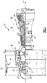
- FIG. 1 schematically illustrates an example gas turbine engine 20 that includes a fan section 22, a compressor section 24, a combustor section 26 and a turbine section 28.
- Alternative engines might include an augmenter section (not shown) among other systems or features.
- the fan section 22 drives air along a bypass flow path B while the compressor section 24 draws air in along a core flow path C where air is compressed and communicated to a combustor section 26.
- air is mixed with fuel and ignited to generate a high pressure exhaust gas stream that expands through the turbine section 28 where energy is extracted and utilized to drive the fan section 22 and the compressor section 24.
- turbofan gas turbine engine depicts a two-spool turbofan gas turbine engine
- the concepts described herein are not limited to use with turbofans as the teachings may be applied to other types of turbine engines; for example a turbine engine including a three-spool architecture in which three spools concentrically rotate about a common axis and where a low spool enables a low pressure turbine to drive a fan via a gearbox, an intermediate spool that enables an intermediate pressure turbine to drive a first compressor of the compressor section, and a high spool that enables a high pressure turbine to drive a high pressure compressor of the compressor section.
- the example engine 20 generally includes a low speed spool 30 and a high speed spool 32 mounted for rotation about an engine central longitudinal axis A relative to an engine static structure 36 via several bearing systems 38. It should be understood that various bearing systems 38 at various locations may alternatively or additionally be provided.
- the low speed spool 30 generally includes an inner shaft 40 that connects a fan 42 and a low pressure (or first) compressor section 44 to a low pressure (or first) turbine section 46.
- the inner shaft 40 drives the fan 42 through a speed change device, such as a geared architecture 48, to drive the fan 42 at a lower speed than the low speed spool 30.
- the high-speed spool 32 includes an outer shaft 50 that interconnects a high pressure (or second) compressor section 52 and a high pressure (or second) turbine section 54.
- the inner shaft 40 and the outer shaft 50 are concentric and rotate via the bearing systems 38 about the engine central longitudinal axis A.
- a combustor 56 is arranged between the high pressure compressor 52 and the high pressure turbine 54.
- the high pressure turbine 54 includes at least two stages to provide a double stage high pressure turbine 54.
- the high pressure turbine 54 includes only a single stage.
- a "high pressure" compressor or turbine experiences a higher pressure than a corresponding "low pressure” compressor or turbine.
- the example low pressure turbine 46 has a pressure ratio that is greater than about 5.
- the pressure ratio of the example low pressure turbine 46 is measured prior to an inlet of the low pressure turbine 46 as related to the pressure measured at the outlet of the low pressure turbine 46 prior to an exhaust nozzle.
- a mid-turbine frame 58 of the engine static structure 36 is arranged generally between the high pressure turbine 54 and the low pressure turbine 46.
- the mid-turbine frame 58 further supports bearing systems 38 in the turbine section 28 as well as setting airflow entering the low pressure turbine 46.
- Airflow through the core airflow path C is compressed by the low pressure compressor 44 then by the high pressure compressor 52 mixed with fuel and ignited in the combustor 56 to produce high speed exhaust gases that are then expanded through the high pressure turbine 54 and low pressure turbine 46.
- the mid-turbine frame 58 includes vanes 60, which are in the core airflow path and function as an inlet guide vane for the low pressure turbine 46. Utilizing the vane 60 of the mid-turbine frame 58 as the inlet guide vane for low pressure turbine 46 decreases the length of the low pressure turbine 46 without increasing the axial length of the mid-turbine frame 58. Reducing or eliminating the number of vanes in the low pressure turbine 46 shortens the axial length of the turbine section 28. Thus, the compactness of the gas turbine engine 20 is increased and a higher power density may be achieved.
- the disclosed gas turbine engine 20 in one example is a high-bypass geared aircraft engine.
- the gas turbine engine 20 includes a bypass ratio greater than about six (6), with an example embodiment being greater than about ten (10).
- the example geared architecture 48 is an epicyclical gear train, such as a planetary gear system, with a gear reduction ratio of greater than about 2.3.
- the gas turbine engine 20 includes a bypass ratio greater than about ten (10:1) and the fan diameter is significantly larger than an outer diameter of the low pressure compressor 44. It should be understood, however, that the above parameters are only exemplary of one embodiment of a gas turbine engine including a geared architecture and that the present disclosure is applicable to other gas turbine engines.
- the fan section 22 of the engine 20 is designed for a particular flight condition -- typically cruise at about 0.8 Mach and about 35,000 feet.
- the flight condition of 0.8 Mach and 35,000 ft., with the engine at its best fuel consumption - also known as "bucket cruise Thrust Specific Fuel Consumption ('TSFC')" - is the industry standard parameter of pound-mass (lbm) of fuel per hour being burned divided by pound-force (lbf) of thrust the engine produces at that minimum point.
- Low fan pressure ratio is the pressure ratio across the fan blade alone, without a Fan Exit Guide Vane (“FEGV”) system.
- the low fan pressure ratio as disclosed herein according to one non-limiting embodiment is less than about 1.50. In another non-limiting embodiment the low fan pressure ratio is less than about 1.45.
- Low corrected fan tip speed is the actual fan tip speed in ft/sec divided by an industry standard temperature correction of [(Tram °R)/(518.7°R)] 0.5 .
- the "Low corrected fan tip speed”, as disclosed herein according to one non-limiting embodiment, is less than about 1150 ft/second.
- the example gas turbine engine includes the fan 42 that comprises in one non-limiting embodiment less than about twenty-six (26) fan blades. In another non-limiting embodiment, the fan section 22 includes less than about twenty (20) fan blades. Moreover, in one disclosed embodiment the low pressure turbine 46 includes no more than about six (6) turbine rotors schematically indicated at 34. In another non-limiting example embodiment the low pressure turbine 46 includes about three (3) turbine rotors. A ratio between the number of fan blades 42 and the number of low pressure turbine rotors is between about 3.3 and about 8.6. The example low pressure turbine 46 provides the driving power to rotate the fan section 22 and therefore the relationship between the number of turbine rotors 34 in the low pressure turbine 46 and the number of blades 42 in the fan section 22 discloses an example gas turbine engine 20 with increased power transfer efficiency.
- the example gas turbine engine 20 includes a fan drive gear system 62 that includes the geared architecture 48.
- the fan drive gear system 62 drives a fan shaft 64 that, in turn, drives the fan blades 42 about the axis A.
- the example geared architecture 48 gear arrangement is referred to as a planetary system and includes intermediate or planet gears 78 supported by a carrier 66.
- the carrier 66 rotates to drive the fan shaft 64.
- the example fan drive gear system 62 includes a carrier 66 that is secured to a torque frame 68 at a plurality of connection interfaces 74 spaced apart circumferentially.
- Each of the connection interfaces includes a connector 70, which may, as shown, be in the form of a pin.
- the carrier 66 supports rotation of the plurality of intermediate gears 78 that are arranged about a sun gear 76.
- the sun gear 76 drives the intermediate or planet gears 78 that are supported within the carrier 66.
- the intermediate gears 78 are circumscribed by a ring gear 80 (schematically shown in Figures 1 and 2 ).
- the ring gear 80 is fixed to a static structure 36 of the gas turbine engine 20 ( Figure 1 ).
- the carrier 66 and torque frame 68 rotate about the axis A in response to rotation of the sun gear 76.
- the carrier 66 and torque frame 68 rotate in the direction indicated by the arrow R about the engine axis A in a direction common with rotation of the sun gear 76.
- the gears 78 are driven by the sun gear 76 and are fed with a lubricant flow that is communicated to the interface between the sun gear 76 and the intermediate gears 78.
- Lubricant that has been flowed through the interface between meshed gears is exhausted outwardly and is typically received within a gutter or other lubricant capture arrangement.
- a portion of that exhausted lubricant indicated by arrows 84 is captured within an accumulator 82 defined within the carrier 66.
- the accumulator 82 captures some of the exhausted lubricant 84 and communicates that lubricant to the interface 74.
- the interface 74 between the torque frame 68 and the carrier 66 is provided through the pin 70. Ends 88 of the pin 70 are attached to the carrier by corresponding press fits 90.
- the press fit 90 of the pin 70 secures the torque frame 68 to the carrier 66.
- the example press fit 90 is an interference fit that provides a desired fit to maintain the ends 88 of the pin 70 within the carrier 66.
- the fit between the torque frame 68 and the pin 70 is a running or clearance fit and includes a space 94. Lubricant is directed through the space 94 to reduce wear and flush out debris.
- Rotation of the fan drive gear system 62 generates a centrifugal force that drives the lubricant 84 radially outward once exhausted from the meshing interface between the sun gear 76 and each of the plurality of the intermediate gears 78.
- the lubricant 84 is captured and channeled towards the interfaces 74 defined between the torque frame 68 and the carrier 66.
- the interfaces 74 between the torque frame 68 and the carrier 66 are the only relative moving elements, other than the gear interface, within the fan drive gear system 62 and therefore may wear undesirably if not properly lubricated.
- the example fan drive gear system 62 channels the exhausted lubricant 84 into the space 94 defined between each of the pins 70 and the torque frame 68.
- the exhausted lubricant 84 is channeled first through the accumulator 82 defined in the carrier 66 towards the interfaces 74 by the centrifugal forces generated by rotation of the carrier 66.
- the lubricant 84 is further directed by scuppers 72 defined on the torque frame 68.
- the scuppers 72 take the lubricant 84 and direct it into the space 94 between the pin 70 and the torque frame 68.
- the scuppers 72 are funnel or scoop shaped features that are formed directly into the torque frame 68 and direct the radially discharged exhaust lubricant 84 towards into the space 94.
- the space 94 is open at each end such that lubricant 84 flow enters and is exhausted from the space 94 to provide a continued replenishment of lubricant between the pin 70 and the torque frame 68.
- another fan drive gear system 65 includes a carrier 100 that is attached to a torque frame 98 through interfaces 75.
- the interfaces 75 include a connector 70 (which may, as shown, be in the form of a pin) secured with a press fit to the torque frame 98 and a running fit with the carrier 100.
- the carrier 100 includes a lubricant scupper 104 that channels exhausted lubricant 84 into a space 106 defined between the pin 70 and the carrier 100.
- the scupper 104 comprises a passage 102 that directs lubricant 84 into the space 106 between the pin 70 and the carrier 100.
- lubricant exhausted from the interface between the sun gear 76 and the intermediate gears 78 is flung radially outward towards the interfaces 75 between the carrier 100 and the torque frame 98. Some of the exhausted lubricant 84 is simply flung radially outward into gutter and other structures (not shown) that are provided to accumulate the exhausted lubricant 84.
- a portion of lubricant 84 is captured by the accumulators 82 defined within the carrier 100 and channeled toward each of the interfaces 75.
- the scupper 104 defines the passage 102 that captures the radially outward flung lubricant 84 and directs that lubricant into the space 106 between the pin 70 and the carrier 100.
- a running fit is provided between the carrier 100 and the pin 70.
- a press fit 96 is provided between the torque frame 98 and the pin 70.
- Lubricant flows through the space 106 and is exhausted as is indicated by arrows 86 to ensure a continued replenishment of lubricant.
- the force and pressures required to drive lubricant into the space 106 and 94 is provided by the centrifugal forces generated by rotation of the carrier 100 and torque frame 98.
- the example interface configuration provides for the continued lubrication of the interface between the torque frame 98 and the carrier 100 without the use of pressurized lubricant flow provided by a pump. Moreover, because lubricant is communicated through scuppers and other oil scavenging configurations arranged on either the torque frame 98 or the carrier 100, complex and difficult to manufacture passages through the pins 70 are not required. Accordingly, the example configuration provides for the lubrication of the interfaces without complex machining by utilizing the centrifugal forces generated during operation.
Landscapes
- Engineering & Computer Science (AREA)
- Chemical & Material Sciences (AREA)
- Combustion & Propulsion (AREA)
- General Engineering & Computer Science (AREA)
- Mechanical Engineering (AREA)
- Retarders (AREA)
- General Details Of Gearings (AREA)
- Architecture (AREA)
- Software Systems (AREA)
Abstract
Description
- This application claims priority to
United States Application No. 14/277,472 filed on May 14, 2014 United States Provisional Application No. 61/869,883 filed on August 26, 2013 - A gas turbine engine typically includes a fan section, a compressor section, a combustor section and a turbine section. Air entering the compressor section is compressed and delivered into the combustion section where it is mixed with fuel and ignited to generate a high-speed exhaust gas flow. The high-speed exhaust gas flow expands through the turbine section to drive the compressor and the fan section.
- A speed reduction device such as an epicyclical gear assembly may be utilized to drive the fan section such that the fan section may rotate at a speed different than the turbine section so as to increase the overall propulsive efficiency of the engine. In such engine architectures, a shaft driven by one of the turbine sections provides an input to the epicyclical gear assembly that drives the fan section at a reduced speed such that both the turbine section and the fan section can rotate at closer to optimal speeds.
- A carrier is provided to support rotation of the gears within the gear assembly. The carrier is attached to a torque frame to accommodate torque loads on the gear assembly. A series of pins extending through both the torque frame and carrier provides the connection between the torque frame and carrier. The pins are the only sliding interface, other than the gears, within the gear assembly and can be a source of wear if not sufficiently lubricated. Pressurized lubricant is communicated through passages within the pins to provide lubricant to the contact interface. Providing passages to and through each of the pins complicates assembly and increases costs. Accordingly, it is desirable to design and develop alternate lubricant arrangements to reduce cost and maintain lubricant efficiencies.
- A turbofan engine according to an exemplary embodiment of this disclosure, among other possible things includes a fan rotatable about an axis, a compressor section, a combustor in fluid communication with the compressor section, a turbine section in fluid communication with the combustor, and a fan drive gear system including a carrier for supporting a plurality of gears. A torque frame is attached to the carrier. A plurality of connectors extends between the carrier and torque frame for securing the torque frame to the carrier. A scupper captures lubricant during gear operation and directing lubricant into a space between at least one of the plurality of connectors and at least one of the torque frame and the carrier.
- In a further embodiment of any of the foregoing turbofan engines, the fan drive gear system includes a sun gear driving a plurality of intermediate gears supported by the carrier and ring gear circumscribing the plurality intermediate gears. The ring gear is fixed relative to rotation of the carrier and torque frame about an axis of rotation.
- In a further embodiment of any of the foregoing turbofan engines, the carrier and torque frame are configured to rotate about an axis of rotation and generate centrifugal forces for driving exhaust lubricant through the space between each of the plurality of connectors and one of the carrier and torque frame.
- In a further embodiment of any of the foregoing turbofan engines, the scupper is a portion of the torque frame.
- In a further embodiment of any of the foregoing turbofan engines, the scupper is a portion of the carrier.
- In a further embodiment of any of the foregoing turbofan engines, the scupper includes a scoop that directs lubricant into the space.
- In a further embodiment of any of the foregoing turbofan engines, the fan drive gear system provides a speed reduction between the turbine section and the fan section of greater than about 2.3.
- In a further embodiment of any of the foregoing turbofan engines, the turbofan engine is a high bypass geared aircraft engine having a bypass ratio of greater than about ten (10).
- In a further embodiment of any of the foregoing turbofan engines, the turbofan engine includes a Fan Pressure Ratio of less than about 1.45.
- In a further embodiment of any of the foregoing turbofan engines, the turbine section includes a fan drive turbine coupled to drive the fan through the fan drive gear system and a second turbine forward of the fan drive turbine and a ratio of a number of fan blades in the fan and a number of rotors in the fan drive turbine is between about 3.3 and about 8.6.
- A fan drive gear system according to an exemplary embodiment of this disclosure, among other possible things includes a carrier for supporting a plurality of gears, a torque frame attached to the carrier, a plurality of connectors extending between the carrier and torque frame for securing the torque frame to the carrier, and a scupper for capturing lubricant during gear operation and directing lubricant into a space between the plurality of connectors and at least one of the torque frame and the carrier.
- In a further embodiment of any of the foregoing fan drive gear systems, the scupper is a portion of the torque frame.
- In a further embodiment of any of the foregoing fan drive gear systems, the plurality of connectors are each press fit at each distal end into the carrier and the space is defined between each connector and the torque frame.
- In a further embodiment of any of the foregoing fan drive gear systems, the carrier includes at least one opening for communicating lubricant to the scupper.
- In a further embodiment of any of the foregoing fan drive gear systems, the scupper is a portion of the carrier.
- In a further embodiment of any of the foregoing fan drive gear systems, the plurality of connectors are press fit at each distal end into the torque frame and the space is defined between each connector and the carrier.
- In a further embodiment of any of the foregoing fan drive gear systems, the scupper includes a scoop that directs lubricant into the space.
- In a further embodiment of any of the foregoing fan drive gear systems, includes a sun gear driving a plurality of intermediate gears supported by the carrier and a ring gear circumscribing the plurality intermediate gears. The ring gear is fixed relative to rotation of the carrier and torque frame about an axis of rotation.
- In a further embodiment of any of the foregoing fan drive gear systems, the carrier and torque frame are configured to rotate about an axis of rotation and generate centrifugal forces for driving exhaust lubricant through the space between each of the plurality of connectors and one of the carrier and torque frame.
- A method of designing a fan drive gear system for a turbofan engine according to an exemplary embodiment of this disclosure, among other possible things includes configuring a torque frame for attachment to a carrier by way of a plurality of connectors, configuring a lubricant flow path such that rotation of the carrier and torque frame generate centrifugal forces in exhaust lubricant, configuring at least one of the carrier and the torque frame with scuppers for capturing at least a portion of lubricant exhausted from a plurality of gears, and configuring the scuppers to direct the captured lubricant into a space between the plurality of connectors and one of the torque frame and carrier.
- In a further embodiment of any of the foregoing methods, the scuppers are defined on the torque frame and the press fit is between each of the plurality of connectors and the carrier.
- In a further embodiment of any of the foregoing methods, the scuppers are defined on the carrier and the press fit is between each of the plurality of connectors and the torque frame.
- In a further embodiment of any of the foregoing methods, includes defining an outlet from the space between the plurality of connectors for exhausting lubricant from the space.
- In a further embodiment of any of the foregoing methods, configures a sun gear to drive the plurality of gears supported by the carrier and configuring a ring gear to circumscribe the plurality of gears such that the ring gear is fixed relative to rotation of the carrier and torque frame about an axis of rotation.
- In a further embodiment of any of the foregoing methods, includes configuring the fan drive gear system to provide a speed reduction ratio greater than about 2.3:1.
- Although the different examples have the specific components shown in the illustrations, embodiments of this disclosure are not limited to those particular combinations. It is possible to use some of the components or features from one of the examples in combination with features or components from another one of the examples.
- These and other features disclosed herein can be best understood from the following specification and drawings, the following of which is a brief description.
-
-
Figure 1 is a schematic view of an example gas turbine engine. -
Figure 2 is a schematic representation of an example fan drive gear system. -
Figure 3 is a schematic cross-sectional view of the example fan drive gear system. -
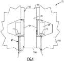
Figure 4 is an enlarged schematic view of an interface between example torque frame and carrier. -
Figure 5 is another schematic representation of another fan drive gear system. -
Figure 6 is a cross-sectional view of the example fan drive gear system shown inFigure 5 . -
Figure 7 is an enlarged cross-section of another interface between a carrier and torque frame. -
Figure 1 schematically illustrates an examplegas turbine engine 20 that includes afan section 22, acompressor section 24, acombustor section 26 and aturbine section 28. Alternative engines might include an augmenter section (not shown) among other systems or features. Thefan section 22 drives air along a bypass flow path B while thecompressor section 24 draws air in along a core flow path C where air is compressed and communicated to acombustor section 26. In thecombustor section 26, air is mixed with fuel and ignited to generate a high pressure exhaust gas stream that expands through theturbine section 28 where energy is extracted and utilized to drive thefan section 22 and thecompressor section 24. - Although the disclosed non-limiting embodiment depicts a two-spool turbofan gas turbine engine, it should be understood that the concepts described herein are not limited to use with turbofans as the teachings may be applied to other types of turbine engines; for example a turbine engine including a three-spool architecture in which three spools concentrically rotate about a common axis and where a low spool enables a low pressure turbine to drive a fan via a gearbox, an intermediate spool that enables an intermediate pressure turbine to drive a first compressor of the compressor section, and a high spool that enables a high pressure turbine to drive a high pressure compressor of the compressor section.
- The
example engine 20 generally includes alow speed spool 30 and ahigh speed spool 32 mounted for rotation about an engine central longitudinal axis A relative to an enginestatic structure 36 viaseveral bearing systems 38. It should be understood thatvarious bearing systems 38 at various locations may alternatively or additionally be provided. - The
low speed spool 30 generally includes aninner shaft 40 that connects afan 42 and a low pressure (or first)compressor section 44 to a low pressure (or first)turbine section 46. Theinner shaft 40 drives thefan 42 through a speed change device, such as a gearedarchitecture 48, to drive thefan 42 at a lower speed than thelow speed spool 30. The high-speed spool 32 includes anouter shaft 50 that interconnects a high pressure (or second)compressor section 52 and a high pressure (or second)turbine section 54. Theinner shaft 40 and theouter shaft 50 are concentric and rotate via the bearingsystems 38 about the engine central longitudinal axis A. - A
combustor 56 is arranged between thehigh pressure compressor 52 and thehigh pressure turbine 54. In one example, thehigh pressure turbine 54 includes at least two stages to provide a double stagehigh pressure turbine 54. In another example, thehigh pressure turbine 54 includes only a single stage. As used herein, a "high pressure" compressor or turbine experiences a higher pressure than a corresponding "low pressure" compressor or turbine. - The example
low pressure turbine 46 has a pressure ratio that is greater than about 5. The pressure ratio of the examplelow pressure turbine 46 is measured prior to an inlet of thelow pressure turbine 46 as related to the pressure measured at the outlet of thelow pressure turbine 46 prior to an exhaust nozzle. - A
mid-turbine frame 58 of the enginestatic structure 36 is arranged generally between thehigh pressure turbine 54 and thelow pressure turbine 46. Themid-turbine frame 58 furthersupports bearing systems 38 in theturbine section 28 as well as setting airflow entering thelow pressure turbine 46. - Airflow through the core airflow path C is compressed by the
low pressure compressor 44 then by thehigh pressure compressor 52 mixed with fuel and ignited in thecombustor 56 to produce high speed exhaust gases that are then expanded through thehigh pressure turbine 54 andlow pressure turbine 46. Themid-turbine frame 58 includesvanes 60, which are in the core airflow path and function as an inlet guide vane for thelow pressure turbine 46. Utilizing thevane 60 of themid-turbine frame 58 as the inlet guide vane forlow pressure turbine 46 decreases the length of thelow pressure turbine 46 without increasing the axial length of themid-turbine frame 58. Reducing or eliminating the number of vanes in thelow pressure turbine 46 shortens the axial length of theturbine section 28. Thus, the compactness of thegas turbine engine 20 is increased and a higher power density may be achieved. - The disclosed
gas turbine engine 20 in one example is a high-bypass geared aircraft engine. In a further example, thegas turbine engine 20 includes a bypass ratio greater than about six (6), with an example embodiment being greater than about ten (10). The example gearedarchitecture 48 is an epicyclical gear train, such as a planetary gear system, with a gear reduction ratio of greater than about 2.3. - In one disclosed embodiment, the
gas turbine engine 20 includes a bypass ratio greater than about ten (10:1) and the fan diameter is significantly larger than an outer diameter of thelow pressure compressor 44. It should be understood, however, that the above parameters are only exemplary of one embodiment of a gas turbine engine including a geared architecture and that the present disclosure is applicable to other gas turbine engines. - A significant amount of thrust is provided by airflow through the bypass flow path B due to the high bypass ratio. The
fan section 22 of theengine 20 is designed for a particular flight condition -- typically cruise at about 0.8 Mach and about 35,000 feet. The flight condition of 0.8 Mach and 35,000 ft., with the engine at its best fuel consumption - also known as "bucket cruise Thrust Specific Fuel Consumption ('TSFC')" - is the industry standard parameter of pound-mass (lbm) of fuel per hour being burned divided by pound-force (lbf) of thrust the engine produces at that minimum point. - "Low fan pressure ratio" is the pressure ratio across the fan blade alone, without a Fan Exit Guide Vane ("FEGV") system. The low fan pressure ratio as disclosed herein according to one non-limiting embodiment is less than about 1.50. In another non-limiting embodiment the low fan pressure ratio is less than about 1.45.
- "Low corrected fan tip speed" is the actual fan tip speed in ft/sec divided by an industry standard temperature correction of [(Tram °R)/(518.7°R)]0.5. The "Low corrected fan tip speed", as disclosed herein according to one non-limiting embodiment, is less than about 1150 ft/second.
- The example gas turbine engine includes the
fan 42 that comprises in one non-limiting embodiment less than about twenty-six (26) fan blades. In another non-limiting embodiment, thefan section 22 includes less than about twenty (20) fan blades. Moreover, in one disclosed embodiment thelow pressure turbine 46 includes no more than about six (6) turbine rotors schematically indicated at 34. In another non-limiting example embodiment thelow pressure turbine 46 includes about three (3) turbine rotors. A ratio between the number offan blades 42 and the number of low pressure turbine rotors is between about 3.3 and about 8.6. The examplelow pressure turbine 46 provides the driving power to rotate thefan section 22 and therefore the relationship between the number ofturbine rotors 34 in thelow pressure turbine 46 and the number ofblades 42 in thefan section 22 discloses an examplegas turbine engine 20 with increased power transfer efficiency. - Referring to
Figure 2 , with continued reference toFigure 1 , the examplegas turbine engine 20 includes a fandrive gear system 62 that includes the gearedarchitecture 48. The fandrive gear system 62 drives afan shaft 64 that, in turn, drives thefan blades 42 about the axis A. - The example geared
architecture 48 gear arrangement is referred to as a planetary system and includes intermediate or planet gears 78 supported by acarrier 66. Thecarrier 66 rotates to drive thefan shaft 64. - Referring to
Figures 2 ,3 and4 with continued reference toFigure 1 , the example fandrive gear system 62 includes acarrier 66 that is secured to atorque frame 68 at a plurality of connection interfaces 74 spaced apart circumferentially. Each of the connection interfaces includes aconnector 70, which may, as shown, be in the form of a pin. - The
carrier 66 supports rotation of the plurality ofintermediate gears 78 that are arranged about asun gear 76. Thesun gear 76 drives the intermediate or planet gears 78 that are supported within thecarrier 66. The intermediate gears 78, in turn, are circumscribed by a ring gear 80 (schematically shown inFigures 1 and2 ). In this example of a fandrive gear system 62, thering gear 80 is fixed to astatic structure 36 of the gas turbine engine 20 (Figure 1 ). Thecarrier 66 andtorque frame 68 rotate about the axis A in response to rotation of thesun gear 76. In this example, thecarrier 66 andtorque frame 68 rotate in the direction indicated by the arrow R about the engine axis A in a direction common with rotation of thesun gear 76. - The
gears 78 are driven by thesun gear 76 and are fed with a lubricant flow that is communicated to the interface between thesun gear 76 and the intermediate gears 78. Lubricant that has been flowed through the interface between meshed gears is exhausted outwardly and is typically received within a gutter or other lubricant capture arrangement. In this example, a portion of that exhausted lubricant indicated byarrows 84 is captured within anaccumulator 82 defined within thecarrier 66. Theaccumulator 82 captures some of theexhausted lubricant 84 and communicates that lubricant to theinterface 74. - The
interface 74 between thetorque frame 68 and thecarrier 66 is provided through thepin 70. Ends 88 of thepin 70 are attached to the carrier by corresponding press fits 90. Thepress fit 90 of thepin 70 secures thetorque frame 68 to thecarrier 66. Theexample press fit 90 is an interference fit that provides a desired fit to maintain theends 88 of thepin 70 within thecarrier 66. - The fit between the
torque frame 68 and thepin 70 is a running or clearance fit and includes aspace 94. Lubricant is directed through thespace 94 to reduce wear and flush out debris. - Rotation of the fan
drive gear system 62 generates a centrifugal force that drives thelubricant 84 radially outward once exhausted from the meshing interface between thesun gear 76 and each of the plurality of the intermediate gears 78. Thelubricant 84 is captured and channeled towards theinterfaces 74 defined between thetorque frame 68 and thecarrier 66. - The
interfaces 74 between thetorque frame 68 and thecarrier 66 are the only relative moving elements, other than the gear interface, within the fandrive gear system 62 and therefore may wear undesirably if not properly lubricated. - The example fan
drive gear system 62 channels theexhausted lubricant 84 into thespace 94 defined between each of thepins 70 and thetorque frame 68. - The
exhausted lubricant 84 is channeled first through theaccumulator 82 defined in thecarrier 66 towards theinterfaces 74 by the centrifugal forces generated by rotation of thecarrier 66. Thelubricant 84 is further directed byscuppers 72 defined on thetorque frame 68. Thescuppers 72 take thelubricant 84 and direct it into thespace 94 between thepin 70 and thetorque frame 68. - In this example, the
scuppers 72 are funnel or scoop shaped features that are formed directly into thetorque frame 68 and direct the radially dischargedexhaust lubricant 84 towards into thespace 94. Thespace 94 is open at each end such thatlubricant 84 flow enters and is exhausted from thespace 94 to provide a continued replenishment of lubricant between thepin 70 and thetorque frame 68. - Referring to
Figures 5, 6 and7 with continued reference toFigure 1 , another fandrive gear system 65 includes acarrier 100 that is attached to atorque frame 98 throughinterfaces 75. Theinterfaces 75 include a connector 70 (which may, as shown, be in the form of a pin) secured with a press fit to thetorque frame 98 and a running fit with thecarrier 100. Thecarrier 100 includes alubricant scupper 104 that channels exhaustedlubricant 84 into aspace 106 defined between thepin 70 and thecarrier 100. In this instance, thescupper 104 comprises apassage 102 that directslubricant 84 into thespace 106 between thepin 70 and thecarrier 100. - In operation, lubricant exhausted from the interface between the
sun gear 76 and theintermediate gears 78 is flung radially outward towards theinterfaces 75 between thecarrier 100 and thetorque frame 98. Some of theexhausted lubricant 84 is simply flung radially outward into gutter and other structures (not shown) that are provided to accumulate theexhausted lubricant 84. - A portion of
lubricant 84 is captured by theaccumulators 82 defined within thecarrier 100 and channeled toward each of theinterfaces 75. In this example, there are fiveinterfaces 75 circumferentially spaced evenly about the periphery of thecarrier 100 and thetorque frame 98. In this example, thescupper 104 defines thepassage 102 that captures the radially outward flunglubricant 84 and directs that lubricant into thespace 106 between thepin 70 and thecarrier 100. - As appreciated in this example, a running fit is provided between the
carrier 100 and thepin 70. Apress fit 96 is provided between thetorque frame 98 and thepin 70. Lubricant flows through thespace 106 and is exhausted as is indicated byarrows 86 to ensure a continued replenishment of lubricant. The force and pressures required to drive lubricant into thespace carrier 100 andtorque frame 98. - Accordingly, the example interface configuration provides for the continued lubrication of the interface between the
torque frame 98 and thecarrier 100 without the use of pressurized lubricant flow provided by a pump. Moreover, because lubricant is communicated through scuppers and other oil scavenging configurations arranged on either thetorque frame 98 or thecarrier 100, complex and difficult to manufacture passages through thepins 70 are not required. Accordingly, the example configuration provides for the lubrication of the interfaces without complex machining by utilizing the centrifugal forces generated during operation. - Although an example embodiment has been disclosed, a worker of ordinary skill in this art would recognize that certain modifications would come within the scope of this disclosure. For that reason, the following claims should be studied to determine the scope and content of this disclosure.
Claims (15)
- A fan drive gear system (62) comprising:a carrier (66;100) for supporting a plurality of gears (78);a plurality of connectors (70) extending between the carrier (66;100) and a structure (68;98) for securing the carrier (66;100) to the structure; characterised by further comprising:
a scupper (72;104) for capturing lubricant during gear operation and directing lubricant into a space (94;106) between one of the plurality of connectors (70) and the carrier (66;100). - The fan drive gear system as recited in claim 1, wherein the scupper (72) is a portion of the carrier (66,100) and the space (94) is disposed between one of the plurality of connectors and the carrier (66. 100).
- The fan drive gear system as recited in claim 2 or 3, wherein the carrier (66) includes at least one opening for communicating lubricant to the scupper (72).
- The fan drive gear system as recited in any preceding claim, wherein the scupper comprises a scoop that directs lubricant into the space.
- The fan drive gear system as recited in any preceding claim, including a sun gear (76) driving a plurality of intermediate gears (78) supported by the carrier (66;100) and a ring gear (80) circumscribing the plurality intermediate gears (78), wherein the ring gear (80) is fixed relative to rotation of the carrier (66;100) and the structure (68;98) about an axis of rotation.
- The fan drive gear system as recited in any preceding claim, wherein the carrier (66;100) is configured to rotate about an axis of rotation and generate centrifugal forces for driving exhaust lubricant through the space (94;106) between each of the plurality of connectors (70) and the carrier (66;100).
- A turbofan engine (20) comprising: a fan (42) rotatable about an axis;a compressor section (24);a combustor (26) in fluid communication with the compressor section (24);a turbine section (28) in fluid communication with the combustor (26); anda fan drive gear system as recited in any preceding claim.
- The turbofan engine as recited in claim 10, wherein the fan drive gear system provides a speed reduction between the turbine section (28) and the fan (22) of greater than 2.3.
- The turbofan engine as recited in claim 10 or 11, wherein the turbofan engine (20) is a high bypass geared aircraft engine having a bypass ratio of greater than ten (10).
- The turbofan engine as recited in any of claims 10 to 12, wherein the turbofan engine (20) includes a Fan Pressure Ratio of less than 1.45.
- The turbofan engine as recited in any of claims 10 to 13, wherein the turbine section (28) includes a fan drive turbine (46) coupled to drive the fan (42) through the fan drive gear system and a second turbine (54) forward of the fan drive turbine (46) and a ratio of a number of fan blades in the fan (42) and a number of rotors in the fan drive turbine (46) is between 3.3 and 8.6.
- A method of designing a fan drive gear system (62) for a turbofan engine (20), the method comprising:configuring a carrier (66; 100) for attachment to a structure by way of a plurality of connectors (70);configuring a lubricant flow path such that rotation of the carrier (66; 100) generate centrifugal forces in exhaust lubricant;configuring the carrier (66; 100) with a scupper (72; 104) for capturing at least a portion of lubricant exhausted from a plurality of gears (78); andconfiguring the scupper (72; 104) to direct the captured lubricant into a space (94; 106) between one of the plurality of connectors (70) and the carrier (66; 100).
- The method as recited in claim 12, wherein the scupper (104) is defined on the carrier.
- The method as recited in claim 12 or 13, including defining an outlet from the space (94; 106) between the plurality of connectors (70) for exhausting lubricant from the space (94; 106).
- The method as recited in any of claims 12 to 14, including:configuring a sun gear (76) to drive the plurality of gears (78) supported by the carrier (66; 100) and configuring a ring gear (80) to circumscribe the plurality of gears (78) such that the ring gear (80) is fixed relative to rotation of the carrier (66; 100) about an axis of rotation; and/orconfiguring the fan drive gear system (62) to provide a speed reduction ratio greater than 2.3:1.
Applications Claiming Priority (4)
| Application Number | Priority Date | Filing Date | Title |
|---|---|---|---|
| US201361869883P | 2013-08-26 | 2013-08-26 | |
| US14/277,472 US8857149B1 (en) | 2013-08-26 | 2014-05-14 | Torque connector lubrication scuppers |
| EP14839500.7A EP3039265B1 (en) | 2013-08-26 | 2014-08-22 | Torque connector lubrication scuppers |
| PCT/US2014/052230 WO2015031178A1 (en) | 2013-08-26 | 2014-08-22 | Torque connector lubrication scuppers |
Related Parent Applications (1)
| Application Number | Title | Priority Date | Filing Date |
|---|---|---|---|
| EP14839500.7A Division EP3039265B1 (en) | 2013-08-26 | 2014-08-22 | Torque connector lubrication scuppers |
Publications (1)
| Publication Number | Publication Date |
|---|---|
| EP4056826A1 true EP4056826A1 (en) | 2022-09-14 |
Family
ID=51660966
Family Applications (2)
| Application Number | Title | Priority Date | Filing Date |
|---|---|---|---|
| EP14839500.7A Active EP3039265B1 (en) | 2013-08-26 | 2014-08-22 | Torque connector lubrication scuppers |
| EP22171451.2A Pending EP4056826A1 (en) | 2013-08-26 | 2014-08-22 | Torque connector lubrication scuppers |
Family Applications Before (1)
| Application Number | Title | Priority Date | Filing Date |
|---|---|---|---|
| EP14839500.7A Active EP3039265B1 (en) | 2013-08-26 | 2014-08-22 | Torque connector lubrication scuppers |
Country Status (3)
| Country | Link |
|---|---|
| US (3) | US8857149B1 (en) |
| EP (2) | EP3039265B1 (en) |
| WO (1) | WO2015031178A1 (en) |
Families Citing this family (13)
| Publication number | Priority date | Publication date | Assignee | Title |
|---|---|---|---|---|
| US10267406B2 (en) * | 2013-07-07 | 2019-04-23 | United Technologies Corporation | Inseparable machined lubricant manifold |
| FR3020658B1 (en) * | 2014-04-30 | 2020-05-15 | Safran Aircraft Engines | LUBRICATION OIL RECOVERY HOOD FOR TURBOMACHINE EQUIPMENT |
| US9869190B2 (en) | 2014-05-30 | 2018-01-16 | General Electric Company | Variable-pitch rotor with remote counterweights |
| FR3027628B1 (en) * | 2014-10-28 | 2019-07-12 | Safran Aircraft Engines | LUBRICATING OIL RECOVERY COVER FOR TURBOMACHINE EQUIPMENT |
| US10072510B2 (en) | 2014-11-21 | 2018-09-11 | General Electric Company | Variable pitch fan for gas turbine engine and method of assembling the same |
| US9726040B2 (en) | 2015-03-27 | 2017-08-08 | Pratt & Whitney Canada Corp. | Fluid delivery system for a gas turbine engine |
| US9989083B2 (en) | 2015-05-26 | 2018-06-05 | Pratt & Whitney Canada Corp. | Seal and bearing assembly for a gas turbine engine and method of assembling same |
| US10100653B2 (en) | 2015-10-08 | 2018-10-16 | General Electric Company | Variable pitch fan blade retention system |
| GB201806239D0 (en) * | 2018-04-17 | 2018-05-30 | Rolls Royce Plc | Lubrication system |
| US11674435B2 (en) | 2021-06-29 | 2023-06-13 | General Electric Company | Levered counterweight feathering system |
| US11795964B2 (en) | 2021-07-16 | 2023-10-24 | General Electric Company | Levered counterweight feathering system |
| US12601271B2 (en) | 2022-10-21 | 2026-04-14 | General Electric Company | Variable pitch fan of a gas turbine engine |
| US12270336B1 (en) * | 2023-09-20 | 2025-04-08 | Rtx Corporation | Fan drive gear system rotating oil baffle |
Citations (3)
| Publication number | Priority date | Publication date | Assignee | Title |
|---|---|---|---|---|
| US20060223664A1 (en) * | 2005-03-15 | 2006-10-05 | United Technologies Corporation | Uninterruptible oil supply in planetary system |
| US7883439B2 (en) * | 2006-07-05 | 2011-02-08 | United Technologies Corporation | Oil baffle for gas turbine fan drive gear system |
| WO2014028089A2 (en) * | 2012-06-05 | 2014-02-20 | United Technologies Corporation | Geared architecture carrier torque frame assembly |
Family Cites Families (17)
| Publication number | Priority date | Publication date | Assignee | Title |
|---|---|---|---|---|
| US2862356A (en) * | 1954-07-16 | 1958-12-02 | Rolls Royce | Bearing arrangements for gas-turbine engines |
| IT1250861B (en) * | 1991-11-12 | 1995-04-21 | Fiat Avio Spa | EPICYCLOIDAL SPEED REDUCER SUITABLE TO BE INSERTED IN THE TRANSMISSION BETWEEN A GAS TURBINE AND THE AIR COMPRESSOR OF AN AIRCRAFT ENGINE. |
| US5466198A (en) * | 1993-06-11 | 1995-11-14 | United Technologies Corporation | Geared drive system for a bladed propulsor |
| US5472383A (en) * | 1993-12-27 | 1995-12-05 | United Technologies Corporation | Lubrication system for a planetary gear train |
| JPH1068461A (en) * | 1996-08-28 | 1998-03-10 | Jatco Corp | Lubrication structure of planetary gear unit |
| DE19960157A1 (en) | 1999-12-14 | 2001-06-21 | Schaeffler Waelzlager Ohg | Lubricant supply for a planetary gear |
| US6223616B1 (en) | 1999-12-22 | 2001-05-01 | United Technologies Corporation | Star gear system with lubrication circuit and lubrication method therefor |
| JP3659158B2 (en) * | 2000-10-20 | 2005-06-15 | 株式会社デンソー | Planetary gear reducer |
| DE10307221A1 (en) | 2003-02-20 | 2004-09-02 | Zf Friedrichshafen Ag | planet |
| FR2853382B1 (en) * | 2003-04-04 | 2006-04-28 | Hispano Suiza Sa | FLEXIBLE BONDING SYSTEM BETWEEN A SATELLITE HOLDER AND THE FIXED SUPPORT IN A SPEED REDUCER |
| WO2008063152A2 (en) * | 2006-10-12 | 2008-05-29 | United Technologies Corporation | Turbofan engine |
| DE102008000900A1 (en) * | 2008-04-01 | 2009-10-08 | Zf Friedrichshafen Ag | planetary gear |
| US8307626B2 (en) | 2009-02-26 | 2012-11-13 | United Technologies Corporation | Auxiliary pump system for fan drive gear system |
| US8230974B2 (en) | 2009-05-22 | 2012-07-31 | United Technologies Corporation | Windmill and zero gravity lubrication system for a gas turbine engine |
| JP5342375B2 (en) * | 2009-08-26 | 2013-11-13 | 三菱重工業株式会社 | Planetary bearing structure |
| US8343002B1 (en) | 2011-06-20 | 2013-01-01 | GM Global Technology Operations LLC | Rotating planetary gear carrier lubrication device |
| US8484942B1 (en) | 2012-05-30 | 2013-07-16 | United Technologies Corporation | Planetary gear system arrangement with auxiliary oil system |
-
2014
- 2014-05-14 US US14/277,472 patent/US8857149B1/en active Active
- 2014-08-22 EP EP14839500.7A patent/EP3039265B1/en active Active
- 2014-08-22 WO PCT/US2014/052230 patent/WO2015031178A1/en not_active Ceased
- 2014-08-22 EP EP22171451.2A patent/EP4056826A1/en active Pending
- 2014-10-09 US US14/510,644 patent/US10309306B2/en active Active
-
2019
- 2019-06-04 US US16/431,050 patent/US11022036B2/en active Active
Patent Citations (3)
| Publication number | Priority date | Publication date | Assignee | Title |
|---|---|---|---|---|
| US20060223664A1 (en) * | 2005-03-15 | 2006-10-05 | United Technologies Corporation | Uninterruptible oil supply in planetary system |
| US7883439B2 (en) * | 2006-07-05 | 2011-02-08 | United Technologies Corporation | Oil baffle for gas turbine fan drive gear system |
| WO2014028089A2 (en) * | 2012-06-05 | 2014-02-20 | United Technologies Corporation | Geared architecture carrier torque frame assembly |
Also Published As
| Publication number | Publication date |
|---|---|
| WO2015031178A1 (en) | 2015-03-05 |
| US20150052873A1 (en) | 2015-02-26 |
| US8857149B1 (en) | 2014-10-14 |
| EP3039265B1 (en) | 2022-05-04 |
| EP3039265A1 (en) | 2016-07-06 |
| US10309306B2 (en) | 2019-06-04 |
| US11022036B2 (en) | 2021-06-01 |
| EP3039265A4 (en) | 2016-09-14 |
| US20190316523A1 (en) | 2019-10-17 |
Similar Documents
| Publication | Publication Date | Title |
|---|---|---|
| US11022036B2 (en) | Torque connector lubrication scuppers | |
| US11365648B2 (en) | Integral gutter and front center body | |
| EP3109417B1 (en) | Lubricant delivery system for planetary fan drive gear system | |
| EP3109412B1 (en) | Geared turbofan with independent flexible ring gears and oil collectors | |
| EP3851653B1 (en) | Geared architecture gas turbine engine with planetary gear oil scavenge | |
| EP3179056B1 (en) | Gear driven turbofan | |
| EP3054139B1 (en) | Fan drive gear system | |
| EP2959129B1 (en) | Auxiliary lubricant supply pump stage integral with main lubricant pump stage | |
| WO2015012923A2 (en) | Turbofan engine front section | |
| US10605112B2 (en) | Fan drive gear system spline oil lubrication scheme | |
| EP3008323B1 (en) | Turbofan engine front section | |
| EP3036420B1 (en) | Load balanced journal bearing pin | |
| EP3084181B1 (en) | Geared turbofan with improved gear system maintainability | |
| EP2900980A2 (en) | Geared turbofan primary and secondary nozzle integration geometry | |
| EP3404215B1 (en) | Gas turbine engine with seal anti-rotation lock |
Legal Events
| Date | Code | Title | Description |
|---|---|---|---|
| PUAI | Public reference made under article 153(3) epc to a published international application that has entered the european phase |
Free format text: ORIGINAL CODE: 0009012 |
|
| STAA | Information on the status of an ep patent application or granted ep patent |
Free format text: STATUS: THE APPLICATION HAS BEEN PUBLISHED |
|
| AC | Divisional application: reference to earlier application |
Ref document number: 3039265 Country of ref document: EP Kind code of ref document: P |
|
| AK | Designated contracting states |
Kind code of ref document: A1 Designated state(s): AL AT BE BG CH CY CZ DE DK EE ES FI FR GB GR HR HU IE IS IT LI LT LU LV MC MK MT NL NO PL PT RO RS SE SI SK SM TR |
|
| STAA | Information on the status of an ep patent application or granted ep patent |
Free format text: STATUS: REQUEST FOR EXAMINATION WAS MADE |
|
| 17P | Request for examination filed |
Effective date: 20230313 |
|
| RBV | Designated contracting states (corrected) |
Designated state(s): AL AT BE BG CH CY CZ DE DK EE ES FI FR GB GR HR HU IE IS IT LI LT LU LV MC MK MT NL NO PL PT RO RS SE SI SK SM TR |
|
| RAP3 | Party data changed (applicant data changed or rights of an application transferred) |
Owner name: RTX CORPORATION |
|
| STAA | Information on the status of an ep patent application or granted ep patent |
Free format text: STATUS: EXAMINATION IS IN PROGRESS |
|
| 17Q | First examination report despatched |
Effective date: 20241112 |