EP4056747A1 - Washing machine having lower balancer - Google Patents
Washing machine having lower balancer Download PDFInfo
- Publication number
- EP4056747A1 EP4056747A1 EP20885670.8A EP20885670A EP4056747A1 EP 4056747 A1 EP4056747 A1 EP 4056747A1 EP 20885670 A EP20885670 A EP 20885670A EP 4056747 A1 EP4056747 A1 EP 4056747A1
- Authority
- EP
- European Patent Office
- Prior art keywords
- washing machine
- fastening
- bead
- hub
- machine according
- Prior art date
- Legal status (The legal status is an assumption and is not a legal conclusion. Google has not performed a legal analysis and makes no representation as to the accuracy of the status listed.)
- Granted
Links
Images


Classifications
-
- D—TEXTILES; PAPER
- D06—TREATMENT OF TEXTILES OR THE LIKE; LAUNDERING; FLEXIBLE MATERIALS NOT OTHERWISE PROVIDED FOR
- D06F—LAUNDERING, DRYING, IRONING, PRESSING OR FOLDING TEXTILE ARTICLES
- D06F37/00—Details specific to washing machines covered by groups D06F21/00 - D06F25/00
- D06F37/20—Mountings, e.g. resilient mountings, for the rotary receptacle, motor, tub or casing; Preventing or damping vibrations
- D06F37/24—Mountings, e.g. resilient mountings, for the rotary receptacle, motor, tub or casing; Preventing or damping vibrations in machines with a receptacle rotating or oscillating about a vertical axis
-
- D—TEXTILES; PAPER
- D06—TREATMENT OF TEXTILES OR THE LIKE; LAUNDERING; FLEXIBLE MATERIALS NOT OTHERWISE PROVIDED FOR
- D06F—LAUNDERING, DRYING, IRONING, PRESSING OR FOLDING TEXTILE ARTICLES
- D06F37/00—Details specific to washing machines covered by groups D06F21/00 - D06F25/00
- D06F37/20—Mountings, e.g. resilient mountings, for the rotary receptacle, motor, tub or casing; Preventing or damping vibrations
- D06F37/24—Mountings, e.g. resilient mountings, for the rotary receptacle, motor, tub or casing; Preventing or damping vibrations in machines with a receptacle rotating or oscillating about a vertical axis
- D06F37/245—Damping vibrations by displacing, supplying or ejecting a material, e.g. liquid, into or from counterbalancing pockets
-
- D—TEXTILES; PAPER
- D06—TREATMENT OF TEXTILES OR THE LIKE; LAUNDERING; FLEXIBLE MATERIALS NOT OTHERWISE PROVIDED FOR
- D06F—LAUNDERING, DRYING, IRONING, PRESSING OR FOLDING TEXTILE ARTICLES
- D06F37/00—Details specific to washing machines covered by groups D06F21/00 - D06F25/00
- D06F37/02—Rotary receptacles, e.g. drums
- D06F37/12—Rotary receptacles, e.g. drums adapted for rotation or oscillation about a vertical axis
-
- F—MECHANICAL ENGINEERING; LIGHTING; HEATING; WEAPONS; BLASTING
- F16—ENGINEERING ELEMENTS AND UNITS; GENERAL MEASURES FOR PRODUCING AND MAINTAINING EFFECTIVE FUNCTIONING OF MACHINES OR INSTALLATIONS; THERMAL INSULATION IN GENERAL
- F16F—SPRINGS; SHOCK-ABSORBERS; MEANS FOR DAMPING VIBRATION
- F16F15/00—Suppression of vibrations in systems; Means or arrangements for avoiding or reducing out-of-balance forces, e.g. due to motion
- F16F15/32—Correcting- or balancing-weights or equivalent means for balancing rotating bodies, e.g. vehicle wheels
- F16F15/36—Correcting- or balancing-weights or equivalent means for balancing rotating bodies, e.g. vehicle wheels operating automatically, i.e. where, for a given amount of imbalance, there is movement of masses until balance is achieved
- F16F15/366—Correcting- or balancing-weights or equivalent means for balancing rotating bodies, e.g. vehicle wheels operating automatically, i.e. where, for a given amount of imbalance, there is movement of masses until balance is achieved using fluid or powder means, i.e. non-discrete material
-
- F—MECHANICAL ENGINEERING; LIGHTING; HEATING; WEAPONS; BLASTING
- F16—ENGINEERING ELEMENTS AND UNITS; GENERAL MEASURES FOR PRODUCING AND MAINTAINING EFFECTIVE FUNCTIONING OF MACHINES OR INSTALLATIONS; THERMAL INSULATION IN GENERAL
- F16F—SPRINGS; SHOCK-ABSORBERS; MEANS FOR DAMPING VIBRATION
- F16F2230/00—Purpose; Design features
- F16F2230/0011—Balancing, e.g. counterbalancing to produce static balance
Definitions
- the present invention relates to a washing machine, and more particularly, to a washing machine which is a top loading washing machine capable of simplifying a number of parts and a manufacturing process by simplifying a fastening structure of a tub base, a lower balancer and a hub.
- a washing machine is a device that washes laundry using the emulsification effect of a detergent, the water flow action generated by the rotation of a washing tub or washing wings, the impacts applied by the washing wings, and the like, and performs a washing cycle, a rinsing cycle or a spin-drying cycle to remove contamination from the laundry using the action of detergent and water.
- a washing machine is divided into a top loading type and a front loading type according to the position of an inlet to which laundry is put, the top loading washing machine has an inlet in a vertical direction, and the front loading washing machine has an inlet in a front-rear direction.
- a top loading washing machine includes an inner tub assembly including an outer tub to store wash water, a drum disposed inside the outer tub and loaded with laundry for washing, and a driving device disposed under the outer tub to rotate the drum.
- upper and lower balancers are mounted on the upper and lower portions of the drum to reduce vibrations generated according to the eccentricity of laundry during washing, rinsing and spin-drying cycles.
- a balancer can be divided into a fluid balancer and a ball balancer according to the type of a vibration reducing mass body, and recently, the fluid balancer is mainly used in consideration of transmission performance and noise generation.
- Korean Patent Laid-Open Publication No. 10-2015-0052454 discloses a top loading washing machine having a configuration in which a lower balancer is coupled and fastened to a hub member to which power is transmitted from a motor, thereby forming an assembly, and then the assembly is attached to a drum base member forming the lower portion of the drum using a separate fastening member.
- the lower balance disclosed in the related document requires a fastening process of fixing the assembly for fastening the hub member and the lower balancer to the drum base member using a separate fastening member, in addition to the fastening member and the fastening process for fixing the lower balancer to the hub member.
- the present invention has been devised to solve the above-described problems, and an object of the present invention is to provide a top loading washing machine capable of significantly reducing the manufacturing process and manufacturing cost by assembling a lower balancer using a fastening structure that connects an existing hub and tub base without adding a fastening member for fastening the lower balancer.
- a washing machine includes a drum in which laundry is accommodated; a tub base which is fixed to a lower end of the drum; a lower balancer which is coupled to an outer circumferential surface of the tub base and reduces vibration generated when the drum rotates; a hub which is coupled to a lower outer surface of the tub base and is disposed radially inside the lower balancer; and at least one integrated fastening member which simultaneously fastens the tub base, the lower balancer and the hub to each other.
- the integrated fastening member includes a fastening bolt which includes a head portion and a body portion integrally formed with the head portion and having a male thread on an outer circumferential surface thereof.
- the tub base includes a disc portion having a through hole through which the body portion passes.
- the tub base includes a reinforcement bead formed to protrude downwardly from the disk portion toward the hub, and a connection bead formed to additionally protrude downward from the reinforcement bead, the through hole is formed through the connection bead.
- the lower balancer includes a fastening tab which extends radially inward and includes a connection hole, the connection bead is at least partially inserted into the connection hole.
- the hub includes a fastening hole having a female thread screwed to the male thread of the body portion, in a state in which the connection bead is inserted into the connection hole, when the male thread of the body portion and the female thread of the fastening hole are screwed together, the head portion presses an upper surface of the connection bead so that a lower surface of the connection bead is in direct contact with an outer surface of the hub, so that the simultaneous fastening between the tub base, the lower balancer and the hub is completed.
- a radially inner end of the fastening tap is provided with an inclined surface which is in contact with the lower surface of the connection bead, and corresponds to a shape of the lower surface of the connection bead.
- the washing machine further includes a washer which is disposed between the head portion and the upper surface of the connection bead to prevent loosening of the fastening bolt.
- the reinforcement bead is formed to protrude to a first depth from the disk portion
- the connection bead is formed to protrude to a second depth from the reinforcement bead, the second depth is smaller than the first depth
- a height from an upper bottom surface of the connection bead to an upper surface of the head portion is smaller than a sum of the first depth and the second depth.
- a height from an upper bottom surface of the connection bead to an upper surface of the head portion is smaller than the first depth.
- a length of the head portion in a longitudinal direction of the fastening bolt is smaller than the second depth.
- the head portion is in direct contact with the upper bottom surface of the connection bead.
- the washing machine further includes an upper balancer fixed to an upper end of the drum, and the upper balancer and the lower balancer are fluid balancers.
- the washing machine according to the present invention has an effect of significantly reducing manufacturing process and manufacturing cost by assembling the lower balancer using a fastening structure for fastening the existing hub and the tub base without adding a fastening member for fastening the lower balancer.
- first and second may be used to describe various components, but the components may not be limited by the terms. The above terms are only for the purpose of distinguishing one component from another.
- a first component may be referred to as a second component, and similarly, a second component may also be referred to as a first component.
- the term "and/or" may include a combination of a plurality of related listed items or any of a plurality of related listed items.
- a component When a component is referred to as being “connected” or “contacted” to another component, it can be understood that it may be directly connected or contacted to the other component, but other components may exist in between. On the other hand, when a component is referred to as being “directly connected” or “directly contacted” to another component, it may be understood that another component does not exist in the middle.
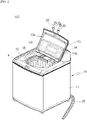
- FIG. 1 is a perspective view of a washing machine 100 according to the present invention.
- a washing machine 100 according to an embodiment of the present invention includes a casing 10 which forms an exterior, an outer tub (not shown) which is disposed inside the casing 10 to store wash water, an inner tub assembly 40 which is disposed inside the outer tub and includes a drum 41 to receive laundry for washing, a driving unit (not shown) which is mounted on the outer tub and rotates the drum 41, and a water supply unit (not shown) and a drain unit (not shown) which supply and drain the wash water.
- the casing 10 includes a top cover 12 which has an inlet on the upper side thereof so that laundry can be put in in a vertical direction, a cabinet 11 which is connected to the top cover 12, and in which the outer tub, the inner tub assembly 40 and the driving unit are installed, and a door 13 which is installed on the top cover 12 and opens and closes the inlet.
- a transparent window 13a is disposed on the door 13 so that the inside of the drum 41 can be observed.
- a control panel 14 is installed on the top cover 12.
- the control panel 14 includes an input unit 14a to which a control command for controlling the operation of the washing machine 100 is input from a user, and a display unit 14b to notify the user of the operating state of the washing machine 100.
- the input unit 14a may be a button, a dial, a touch pad and the like, and the display unit 14b may be an LCD or LED display device.
- top cover 12 is provided with a drawer housing (not shown) which removably accommodates a drawer 18 in which detergent to be put during the washing and rinsing cycles is stored.
- the inside of the drawer 18 is partitioned into a plurality of spaces to store detergents by type. Therefore, laundry detergent, fabric softener, bleach and the like may be separately stored in the plurality of partitioned spaces without mixing with each other.
- the water supply unit includes a water supply pipe, a water supply valve and a dispenser.
- the water supply pipe guides the wash water supplied to the inside of the washing machine 100 from an external water supply source 20 such as a faucet.
- the water supply valve controls the supply of wash water by opening and closing the water supply pipe.
- wash water passing through the control valve is selectively distributed for each space partitioned in the drawer 18 through the dispenser.
- the wash water distributed through the dispenser is mixed with detergent through the drawer 18 and then supplied to the outer tub.
- the drain unit includes a drain pipe (not shown), a drain valve (not shown) and a drain pump (not shown).
- the drain pipe is connected to the outer tub to discharge wash water to the outside, and the drain valve opens and closes the drain pipe to control the discharge of wash water.
- the wash water discharged when the drain valve is opened is pressurized by the drain pump and discharged to the outside through a drain hose 30.
- the driving unit may include an electric motor (not shown), a reduction mechanism (not shown) and a driving shaft (not shown), and is fixed to the lower surface of the outer tub.
- the driving motor provides a driving force for rotations of the drum 41 and a pulsator 50, and an outer rotor type BLDC motor is preferable.
- the detailed configuration of the driving motor is omitted because a technique generally known in the art is applicable.
- the reduction mechanism serves to convert the rotational force of the driving motor into two outputs rotated in opposite directions, and a planetary gear assembly is preferable.
- the rotational force reduced through the planetary gear assembly is transmitted to the driving shaft.
- the driving shaft includes a dual shaft structure having an inner shaft (not shown) and an outer shaft (not shown). One end of the inner shaft extends through the outer shaft and the tub base 42 and is coupled to the pulsator 50, and the other end of the inner shaft extends downward and is connected to the reduction mechanism.
- the outer shaft is manufactured in a tubular shape with a hollow, and the inner shaft is inserted into the hollow.
- the outer shaft passes through the lower side of the outer tub and is coupled to the spline boss 451a of the hub 45.
- the outer shaft and the hub 45 may be spline-coupled.
- teeth FIG. 11
- teeth are formed on the inner peripheral surface of the spline boss 451a.
- the driving motor can selectively drive at least one of the drum 41 and the pulsator 50 or simultaneously drive the drum 41 and the pulsator 50 through the inner shaft and the outer shaft, and such selective driving and simultaneous driving are techniques generally known in the art. Thus, detailed description is omitted.
- the outer tub stores the wash water and is supported by the cabinet 11 through a suspension module (not shown).
- the suspension module cushions the transmitted vibration or shock generated by the outer tub.
- the inner tub assembly 40 is disposed inside the outer tub, and may be rotated in a forward or reverse direction by a rotational force transmitted from the driving unit.
- an assembly including the drum 41, an upper balancer 43, a tub base 42, a lower balancer 44, and a hub 45 will be defined as the inner tub assembly 40 and will be described in detail.
- the inner tub assembly 40 is configured to include the drum 41, the upper balancer 43 provided at the upper end of the drum 41, the tub base 42 fixed to the lower end of the drum 41, the lower balancer 44 coupled to the outside of the tub base 42, the hub 45 fixed to the lower surface of the tub base 42 and an integrated fastening member to fasten the tub base 42, the lower balancer 44 and the hub 45 each other at the same time.
- the drum 41 may be manufactured by processing a lightweight metal plate, preferably an aluminum plate, into a cylindrical shape, and it includes a plurality of through holes 41h.
- the wash water flows into the drum 41 from the outer tub through the plurality of through holes 41h, or the wash water is discharged from the drum 41 to the outer tub.
- the tub base 42 corresponds to a portion fixed to the lower end of the drum 41 and may be manufactured by press-processing of a metal plate.
- the tub base 42 is configured to include a disk portion 421, a step portion 422 and an enlarged diameter portion 423.
- the disk portion 421 is formed in a ring shape with a center hole 421h in the center.
- the wash water is discharged through the center hole 421h, and the above-described driving shaft extends therethrough.
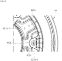
- a plurality of reinforcement beads 421a-1, 421a-2 is formed in the disk portion 421 through press-processing.
- the plurality of reinforcement beads 421a-1, 421a-2 serves to reinforce the rigidity of the disk portion 421 and is formed to protrude downward.
- the reinforcement beads 421a-1, 421a-2 are formed in the upper direction of the disk portion 421, the laundry accommodation space formed by the tub base 42 and the drum 41 is reduced, and accordingly, the washing capacity of the washing machine 100 may be limited. Therefore, it is preferable to form the reinforcement beads 421a-1, 421a-2 to protrude downward so that the washing capacity of the washing machine 100 is not limited.
- At least one of the reinforcement beads 421a-1 and 421a-2 is formed with a connection bead 421b that is formed to further protrude downward from the reinforcement bead 421a-2.
- connection bead 421b acts as a locking portion that is at least partially inserted into the connection hole 442bh formed in the fastening tab 442b of the lower balancer 44 to be described later.
- connection beads 421b are formed at equal intervals.
- the present invention is not limited thereto, it will be described based on a configuration in which a total of six connection beads 421b are formed at equal intervals by way of example.
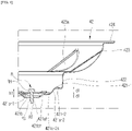
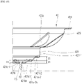
- the reinforcement bead 421a-2 may protrude from the upper bottom surface 421-1 of the disk portion 421 to have a first depth (d1), and the connection bead 421b may protrude from the upper bottom surface 421a-2s of the reinforcement bead 421a-2 to have a second depth (d2).
- the first depth (d1) and the second depth (d2) may be the same or different from each other.
- the second depth (d2) is smaller than the first depth (d1).
- first depth (d1) of the reinforcement bead 421a-2 and the second depth (d2) of the connection bead 421b may be further specified with respect to the height of the head portion (RH) of the fastening bolt (R) as an integrated fastening member to be described later. Details will be described later.
- the through hole 421bh is formed in the individual connection beads 421b.
- the body portion (RS) of the fastening bolt (R) passes through the through hole 421bh.
- the step portion 422 is a portion formed by press-processing so as to be bent upward from the disk portion 421, and is integrally formed with the disk portion 421.
- the step portion 422 internally forms a mounting space for at least partially accommodating the pulsator 50 together with the disk portion 421.
- step portion 422 externally comes into contact with the locking protrusion 442a of the lower balancer 44 to be described later. Accordingly, the contact area between the tub base 42 and the lower balancer 44 may be increased.
- the enlarged diameter portion 423 is a portion in which the inner diameter is expanded and extended from the upper end of the step portion 422.
- the enlarged diameter portion 423 is a portion expanded from the upper end of the step portion 422, and is formed of inner and outer surfaces having a predetermined curvature, and a downwardly convex curved surface.
- the enlarged diameter portion 423 is integrally formed with the step portion 422 through press-processing.
- a reinforcement bead 423a may be formed in the enlarged diameter portion 423 similarly to a flat plate portion.
- the reinforcement bead 423a of the enlarged diameter portion 423 is formed to protrude toward the inside of the drum 41 in an upward direction, unlike the reinforcement beads 421a-1, 421a-2 of the flat plate portion. This is to reinforce the strength of the enlarged diameter part 423 and at the same time, to form a water flow when the inner tub assembly 40 rotates.
- the upper end of the enlarged diameter portion 423 forms a coupling portion 424 which is firmly fixed to the lower end of the drum 41 by welding and curling.
- the outer surface of the enlarged diameter portion 423 forms a space in which the lower balancer 44 is mounted.
- the lower balancer 44 is coupled to the tub base 42 in a simple fitting manner while moving upward in a space having a shape defined by the step portion 422 and the enlarged diameter portion 423.
- the temporary assembly state can be maintained without the use of a separate jig until the hub 45 to be described later is fastened to the lower surface of the tub base 42.
- the upper balancer 43 and the lower balancer 44 serve to reduce the vibrations generated when the inner tub assembly 40 rotates.
- At least one annular cavity 44a defining a movement path of the liquid moving according to the eccentricity of the inner tub assembly 40 is formed in the upper balancer 43 and the lower balancer 44 for vibration reduction.
- the upper balancer 43 may be fixed to the upper end of the drum 41 as a way already known in the art, and thus, a detailed description thereof will be omitted.
- the illustrated embodiment shows the lower balancer 44 which includes an annular cavity 44a having a first cavity, a second cavity and a third cavity.
- this is merely exemplary, and the number and shape of the annular cavity 44a may be variously modified and applied. For convenience, the following description is based on the illustrated embodiment.
- the lower balancer 44 includes a first annular housing 441 corresponding to the upper housing and a second annular housing 442 corresponding to the lower housing.
- annular cavity 44a is formed by the internal structure defined by the first housing 441 and the second housing 442.
- the first housing 441 and the second housing 442 have an outer shape corresponding to a shape defined by the step portion 422 and enlarged diameter portion 423 of the tub base 42 described above.
- the upper outer surface and radially inner outer surface of the first housing 441 are configured to have shapes corresponding to the outer surface shape of the enlarged diameter portion 423 and the outer surface shape of the step portion 422 of the tub base 42.
- the radially inner outer surface of the second housing 442 is configured to have a shape corresponding to the outer surface shape of the step portion 422.
- the second housing 442 includes an annular locking protrusion 442a extending from the radially inner outer surface toward the radially inner side.
- the annular locking protrusion 442a is a portion formed integrally protruding from the second housing 442, and serves to reinforce the strength of the lower balancer 44.
- the amount of protrusion of the annular locking protrusion 442a may be limited to a range not in contact with the reinforcement beads 421a-1, 421a-2 in order to prevent interference with the reinforcement beads 421a-1, 421a-2 of the tub base 42 described above.
- annular locking protrusion 442a is in direct contact with the lower bottom surface 421-2 of the disk portion 421 of the tub base 42.
- the contact area between the tub base 42 and the lower balancer 44 can be increased, and through this, the load transferred from the tub base 42 to the lower balancer 44 is distributed to prevent the lower balancer 44 from being damaged.
- the fastening tab 442b is integrally provided at the radially inner end of the annular locking protrusion 442a.
- the fastening tab 442b of the lower balancer 44 is formed to protrude radially inward from the inner end of the annular locking protrusion 442a.
- the fastening tab 442b may have a shape in which the width gradually decreases while facing the radially inward as illustrated in order to reduce weight and cost.
- the fastening tab 442b is provided with a connection hole 442bh through which the aforementioned connection bead 421b can pass at least partially.
- connection bead 421b penetrates the connection hole 442bh of the fastening tab 442b and is in close contact with the upper surface of the annular flange 453 of the hub 45.
- the radially inner end of the fastening tab 442b is formed to have a predetermined inclined surface 442b-1.
- the inclined surface 442b-1 of the fastening tab 442b has a shape corresponding to the lower outer shape of the connection bead 421b as shown in FIG. 5 . Accordingly, the contact area between the fastening tab 442b and the connection bead 421b of the tub base 42 is enlarged, so that there is an effect of dispersing the load transferred from the tub base 42 to the fastening tab 442b.
- connection bead 421b of the tub base 42 When the connection bead 421b of the tub base 42 is inserted into the connection hole 442bh of the fastening tab 442b, the temporary assembly between the tub base 42 and the lower balancer 44 is completed.
- the hub 45 is coupled to the lower outer surface of the tub base 42.
- tub base 42, the lower balancer 44 and the hub 45 of the washing machine 100 are simultaneously fastened through at least one integrated fastening member.
- the integrated fastening member may be a fastening bolt (R) which includes a head portion (RH), a body portion (RS) extending in a longitudinal direction from the head portion (RH), and a male screw portion (RT) formed at least partially on an outer circumferential surface of the body portion (RS).
- R fastening bolt
- RS body portion
- RT male screw portion
- the hub 45 is coupled to the lower surface of the tub base 42 in a state where the tub base 42 and the lower balancer 44 are temporarily assembled.
- the through hole 421bh of the connection bead 421b of the tub base 42, the connection hole 442bh of the fastening tab 442b of the lower balancer 44 and the fastening hole 453h of the hub 45 are all concentric.
- the body portion (RS) of the fastening bolt (R) is moved downward to extend to the fastening hole 453h through the through hole 421bh and the connection hole 442bh.
- the male screw portion (RT) formed on the body portion (RS) of the fastening bolt (R) may be screwed to a female screw portion formed on the inner circumferential surface of the fastening hole 453h of the hub 45 or may be coupled to a separate nut member.
- connection bead 421b As the male thread portion (RT) of the fastening bolt (R) is screwed to the female thread portion of the hub 45, the fastening bolt (R) moves while rotating in the downward direction, and the head portion (RH) of the fastening bolt (R) presses the upper bottom surface 421b-1 of the connection bead 421b, thereby bring the connection bead 421b into close contact with the upper surface of the hub 45.
- At least one washer may be disposed between the head portion (RH) of the fastening bolt (R) and the upper bottom surface 421b-1 of the connection bead 421b.
- FIG. 5 shows an embodiment in which a flat washer and a plate washer are simultaneously applied. It is possible to prevent loosening of the screw connection between the fastening bolt (R) and the hub 45 through these washers.
- these washers may be configured to be disposed on the nut side.
- FIG. 4 shows an embodiment in which a total of two fastening bolts (Rs) are provided, but the present invention is not limited thereto, and various modifications are possible according to the required coupling strength.
- the number of fastening bolts (Rs) is adjustable within a quantity range that maximizes the number of fastening tabs 442b of the lower balancer 44.
- the height (hi) of the head portion (RH) of the fastening bolt (R) may be additionally specified in relation to the first depth (d1) of the reinforcement bead 421a-2 and the second depth (d2) of the connection bead 421b.
- the height (hi) from the upper bottom surface 421b-1 of the connection bead 421b to the upper surface of the head portion (RH) of the fastening bolt (R) is set smaller than the sum of the first depth (d1) of the reinforcement bead 421a-2 and the second depth (d2) of the connection bead 421b.
- the height (hi) from the upper bottom surface 421b-1 of the connection bead 421b to the upper surface of the head portion (RH) of the fastening bolt (R) is set to be smaller than the second depth (d2) of the connection bead 421b.
- This may be defined as a state in which the head portion (RH) of the fastening bolt (R) is in direct contact with the upper bottom surface 421b-1 of the connection bead 421b, and in this case, the height (hi) of the head portion (RH) may be the same number as the length of the head portion (RH) in the longitudinal direction of the fastening bolt (R).
- the height (hi) or the length of the head portion (RH) of the fastening bolt (R) can be minimized. Accordingly, the height of the step portion 422 of the tub base 42 can be minimized, and the overall height size of the inner tub assembly 40 can be reduced.
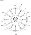
- FIG. 11 shows a top view of the hub 45.
- the hub 45 is disposed between the tub base 42 and the driving unit, and is fixed to the lower outer surface of the tub base 42 through the fastening bolt (R).
- a plurality of fastening holes 453h through which the fastening bolt (R) passes is formed in the annular flange 453 of the hub 45, and a female screw portion may be formed on the inner circumferential surface of the fastening hole 453h.
- the inner surface of the annular flange 453 is connected to the central portion 451 through a plurality of spokes 452.
- connection protrusion 452a protruding upwardly is formed in some of the plurality of spokes 452.
- the connection protrusion 452a is inserted into the locking hole 421a-1h formed in the reinforcement bead 421a-1 of the tub base 42.
- the rotational force transmitted from the hub 45 to the tub base 42 through the connection protrusion 452a may be distributed without being concentrated on the fastening bolt (R).
- the above-described spline boss 451a is formed in the central portion 451, and a spline hole 451h for spline coupling is formed on the inner circumferential surface of the spline boss 451a.
- the teeth of the spline hole 451h are joined to the spline teeth formed on the outer shaft of the driving unit to form a spline coupling.
Landscapes
- Engineering & Computer Science (AREA)
- Textile Engineering (AREA)
- General Engineering & Computer Science (AREA)
- Physics & Mathematics (AREA)
- Acoustics & Sound (AREA)
- Aviation & Aerospace Engineering (AREA)
- Mechanical Engineering (AREA)
- Main Body Construction Of Washing Machines And Laundry Dryers (AREA)
Abstract
Description
- The present invention relates to a washing machine, and more particularly, to a washing machine which is a top loading washing machine capable of simplifying a number of parts and a manufacturing process by simplifying a fastening structure of a tub base, a lower balancer and a hub.
- In general, a washing machine is a device that washes laundry using the emulsification effect of a detergent, the water flow action generated by the rotation of a washing tub or washing wings, the impacts applied by the washing wings, and the like, and performs a washing cycle, a rinsing cycle or a spin-drying cycle to remove contamination from the laundry using the action of detergent and water.
- A washing machine is divided into a top loading type and a front loading type according to the position of an inlet to which laundry is put, the top loading washing machine has an inlet in a vertical direction, and the front loading washing machine has an inlet in a front-rear direction.
- In general, a top loading washing machine includes an inner tub assembly including an outer tub to store wash water, a drum disposed inside the outer tub and loaded with laundry for washing, and a driving device disposed under the outer tub to rotate the drum.
- On the other hand, upper and lower balancers are mounted on the upper and lower portions of the drum to reduce vibrations generated according to the eccentricity of laundry during washing, rinsing and spin-drying cycles.
- A balancer can be divided into a fluid balancer and a ball balancer according to the type of a vibration reducing mass body, and recently, the fluid balancer is mainly used in consideration of transmission performance and noise generation.
- In general, since a lower balancer is installed on the lower side of a drum, a means for fixing the lower balancer to the drum must be added.
- In this regard,
Korean Patent Laid-Open Publication No. 10-2015-0052454 - However, the lower balance disclosed in the related document requires a fastening process of fixing the assembly for fastening the hub member and the lower balancer to the drum base member using a separate fastening member, in addition to the fastening member and the fastening process for fixing the lower balancer to the hub member.
- Therefore, since the fastening means and fastening process for fastening the lower balancer to the lower portion of the drum are added, there is a problem in that overall manufacturing time and manufacturing cost of the washing machine are increased.
- The present invention has been devised to solve the above-described problems, and an object of the present invention is to provide a top loading washing machine capable of significantly reducing the manufacturing process and manufacturing cost by assembling a lower balancer using a fastening structure that connects an existing hub and tub base without adding a fastening member for fastening the lower balancer.
- In order to achieve the above object, a washing machine according to the present invention includes a drum in which laundry is accommodated; a tub base which is fixed to a lower end of the drum; a lower balancer which is coupled to an outer circumferential surface of the tub base and reduces vibration generated when the drum rotates; a hub which is coupled to a lower outer surface of the tub base and is disposed radially inside the lower balancer; and at least one integrated fastening member which simultaneously fastens the tub base, the lower balancer and the hub to each other.
- In addition, the integrated fastening member includes a fastening bolt which includes a head portion and a body portion integrally formed with the head portion and having a male thread on an outer circumferential surface thereof.
- In addition, the tub base includes a disc portion having a through hole through which the body portion passes.
- In addition, the tub base includes a reinforcement bead formed to protrude downwardly from the disk portion toward the hub, and a connection bead formed to additionally protrude downward from the reinforcement bead, the through hole is formed through the connection bead.
- In addition, the lower balancer includes a fastening tab which extends radially inward and includes a connection hole, the connection bead is at least partially inserted into the connection hole.
- In addition, the hub includes a fastening hole having a female thread screwed to the male thread of the body portion, in a state in which the connection bead is inserted into the connection hole, when the male thread of the body portion and the female thread of the fastening hole are screwed together, the head portion presses an upper surface of the connection bead so that a lower surface of the connection bead is in direct contact with an outer surface of the hub, so that the simultaneous fastening between the tub base, the lower balancer and the hub is completed.
- In addition, a radially inner end of the fastening tap is provided with an inclined surface which is in contact with the lower surface of the connection bead, and corresponds to a shape of the lower surface of the connection bead.
- In addition, the washing machine further includes a washer which is disposed between the head portion and the upper surface of the connection bead to prevent loosening of the fastening bolt.
- In addition, the reinforcement bead is formed to protrude to a first depth from the disk portion, the connection bead is formed to protrude to a second depth from the reinforcement bead, the second depth is smaller than the first depth.
- In addition, in a state in which the simultaneous fastening between the tub base, the lower balancer and the hub is completed, a height from an upper bottom surface of the connection bead to an upper surface of the head portion is smaller than a sum of the first depth and the second depth.
- In addition, in a state in which the simultaneous fastening between the tub base, the lower balancer and the hub is completed, a height from an upper bottom surface of the connection bead to an upper surface of the head portion is smaller than the first depth.
- In addition, a length of the head portion in a longitudinal direction of the fastening bolt is smaller than the second depth.
- In addition, the head portion is in direct contact with the upper bottom surface of the connection bead.
- In addition, the washing machine further includes an upper balancer fixed to an upper end of the drum, and the upper balancer and the lower balancer are fluid balancers.
- The washing machine according to the present invention has an effect of significantly reducing manufacturing process and manufacturing cost by assembling the lower balancer using a fastening structure for fastening the existing hub and the tub base without adding a fastening member for fastening the lower balancer.
-
-
FIG. 1 is a perspective view of a washing machine according to the present invention. -
FIG. 2 is a front cross-sectional view of an inner tub assembly of a washing machine according to the present invention. -
FIG. 3 is a perspective view illustrating a state in which a tub base, a lower balancer and a hub of the inner tub assembly shown inFIG. 2 are assembled. -
FIG. 4 is an exploded perspective view ofFIG. 3 . -
FIG. 5 is a partial cross-sectional view ofFIG. 4 -
FIG. 6 is a plan view and a partially enlarged view of a tub base. -
FIGS. 7 and8 are partial cross-sectional views ofFIG. 6 . -
FIG. 9 is a bottom view for explaining a state in which a tub base and a lower balancer are assembled. -
FIG. 10 is a plan view and a partially enlarged view of a lower balancer. -
FIG. 11 is a plan view of a hub. - Hereinafter, preferred embodiments of the present invention will be described in detail with reference to the accompanying drawings.
- Since the present invention can have various changes and can have various embodiments, specific embodiments are illustrated in the drawings and will be described in detail in the detailed description. This is not intended to limit the present invention to specific embodiments, and should be construed to include all modifications, equivalents, and substitutes included in the spirit and scope of the present invention.
- In describing the present invention, terms such as first and second may be used to describe various components, but the components may not be limited by the terms. The above terms are only for the purpose of distinguishing one component from another. For example, without departing from the scope of the present invention, a first component may be referred to as a second component, and similarly, a second component may also be referred to as a first component.
- The term "and/or" may include a combination of a plurality of related listed items or any of a plurality of related listed items.
- When a component is referred to as being "connected" or "contacted" to another component, it can be understood that it may be directly connected or contacted to the other component, but other components may exist in between. On the other hand, when a component is referred to as being "directly connected" or "directly contacted" to another component, it may be understood that another component does not exist in the middle.
- The terms used in the present application are only used to describe specific embodiments, and are not intended to limit the present invention. The singular expression may include the plural expression unless the context clearly dictates otherwise.
- In the present application, terms such as "comprise" or "have" are intended to designate that a feature, number, step, operation, component, part, or combination thereof described in the specification exists, and it may be understood that the existence or addition of one or more other features, numbers, steps, operations, components, parts, or combinations thereof is not precluded in advance.
- Unless defined otherwise, all terms used herein, including technical or scientific terms, may have the same meaning as commonly understood by one of ordinary skill in the art to which this invention belongs. Terms such as those defined in a commonly used dictionary may be interpreted as having a meaning consistent with the meaning in the context of the related art, and unless explicitly defined in the present application, it may not be interpreted in an ideal or excessively formal meaning.
- In addition, the following embodiments are provided to more completely explain to those of ordinary skill in the art, and the shapes and sizes of elements in the drawings may be exaggerated for clearer explanation.
-
FIG. 1 is a perspective view of awashing machine 100 according to the present invention. Referring toFIG. 1 , awashing machine 100 according to an embodiment of the present invention includes acasing 10 which forms an exterior, an outer tub (not shown) which is disposed inside thecasing 10 to store wash water, aninner tub assembly 40 which is disposed inside the outer tub and includes adrum 41 to receive laundry for washing, a driving unit (not shown) which is mounted on the outer tub and rotates thedrum 41, and a water supply unit (not shown) and a drain unit (not shown) which supply and drain the wash water. - The
casing 10 includes atop cover 12 which has an inlet on the upper side thereof so that laundry can be put in in a vertical direction, acabinet 11 which is connected to thetop cover 12, and in which the outer tub, theinner tub assembly 40 and the driving unit are installed, and adoor 13 which is installed on thetop cover 12 and opens and closes the inlet. - A
transparent window 13a is disposed on thedoor 13 so that the inside of thedrum 41 can be observed. - A
control panel 14 is installed on thetop cover 12. Thecontrol panel 14 includes aninput unit 14a to which a control command for controlling the operation of thewashing machine 100 is input from a user, and adisplay unit 14b to notify the user of the operating state of thewashing machine 100. - The
input unit 14a may be a button, a dial, a touch pad and the like, and thedisplay unit 14b may be an LCD or LED display device. - In addition, the
top cover 12 is provided with a drawer housing (not shown) which removably accommodates adrawer 18 in which detergent to be put during the washing and rinsing cycles is stored. - The inside of the
drawer 18 is partitioned into a plurality of spaces to store detergents by type. Therefore, laundry detergent, fabric softener, bleach and the like may be separately stored in the plurality of partitioned spaces without mixing with each other. - The water supply unit includes a water supply pipe, a water supply valve and a dispenser.
- The water supply pipe guides the wash water supplied to the inside of the
washing machine 100 from an externalwater supply source 20 such as a faucet. - The water supply valve controls the supply of wash water by opening and closing the water supply pipe.
- Meanwhile, the wash water passing through the control valve is selectively distributed for each space partitioned in the
drawer 18 through the dispenser. The wash water distributed through the dispenser is mixed with detergent through thedrawer 18 and then supplied to the outer tub. - The drain unit includes a drain pipe (not shown), a drain valve (not shown) and a drain pump (not shown).
- The drain pipe is connected to the outer tub to discharge wash water to the outside, and the drain valve opens and closes the drain pipe to control the discharge of wash water.
- The wash water discharged when the drain valve is opened is pressurized by the drain pump and discharged to the outside through a drain hose 30.
- The driving unit may include an electric motor (not shown), a reduction mechanism (not shown) and a driving shaft (not shown), and is fixed to the lower surface of the outer tub.
- The driving motor provides a driving force for rotations of the
drum 41 and apulsator 50, and an outer rotor type BLDC motor is preferable. - The detailed configuration of the driving motor is omitted because a technique generally known in the art is applicable.
- The reduction mechanism serves to convert the rotational force of the driving motor into two outputs rotated in opposite directions, and a planetary gear assembly is preferable.
- The rotational force reduced through the planetary gear assembly is transmitted to the driving shaft.
- The driving shaft includes a dual shaft structure having an inner shaft (not shown) and an outer shaft (not shown). One end of the inner shaft extends through the outer shaft and the
tub base 42 and is coupled to thepulsator 50, and the other end of the inner shaft extends downward and is connected to the reduction mechanism. - The outer shaft is manufactured in a tubular shape with a hollow, and the inner shaft is inserted into the hollow. The outer shaft passes through the lower side of the outer tub and is coupled to the
spline boss 451a of thehub 45. - In order to transmit a driving force to the
hub 45 through the outer shaft, the outer shaft and thehub 45 may be spline-coupled. To this end, teeth (FIG. 11 ) are formed on the inner peripheral surface of thespline boss 451a. - Therefore, the driving motor can selectively drive at least one of the
drum 41 and thepulsator 50 or simultaneously drive thedrum 41 and thepulsator 50 through the inner shaft and the outer shaft, and such selective driving and simultaneous driving are techniques generally known in the art. Thus, detailed description is omitted. - The outer tub stores the wash water and is supported by the
cabinet 11 through a suspension module (not shown). The suspension module cushions the transmitted vibration or shock generated by the outer tub. - The
inner tub assembly 40 is disposed inside the outer tub, and may be rotated in a forward or reverse direction by a rotational force transmitted from the driving unit. - Hereinafter, an assembly including the
drum 41, anupper balancer 43, atub base 42, alower balancer 44, and ahub 45 will be defined as theinner tub assembly 40 and will be described in detail. - Referring to
FIGS. 2 to 5 , theinner tub assembly 40 according to an embodiment of the present invention is configured to include thedrum 41, theupper balancer 43 provided at the upper end of thedrum 41, thetub base 42 fixed to the lower end of thedrum 41, thelower balancer 44 coupled to the outside of thetub base 42, thehub 45 fixed to the lower surface of thetub base 42 and an integrated fastening member to fasten thetub base 42, thelower balancer 44 and thehub 45 each other at the same time. - The
drum 41 may be manufactured by processing a lightweight metal plate, preferably an aluminum plate, into a cylindrical shape, and it includes a plurality of throughholes 41h. - The wash water flows into the
drum 41 from the outer tub through the plurality of throughholes 41h, or the wash water is discharged from thedrum 41 to the outer tub. - The
tub base 42 corresponds to a portion fixed to the lower end of thedrum 41 and may be manufactured by press-processing of a metal plate. - As shown, the
tub base 42 is configured to include adisk portion 421, astep portion 422 and anenlarged diameter portion 423. - The
disk portion 421 is formed in a ring shape with acenter hole 421h in the center. The wash water is discharged through thecenter hole 421h, and the above-described driving shaft extends therethrough. - A plurality of
reinforcement beads 421a-1, 421a-2 is formed in thedisk portion 421 through press-processing. The plurality ofreinforcement beads 421a-1, 421a-2 serves to reinforce the rigidity of thedisk portion 421 and is formed to protrude downward. - When the
reinforcement beads 421a-1, 421a-2 are formed in the upper direction of thedisk portion 421, the laundry accommodation space formed by thetub base 42 and thedrum 41 is reduced, and accordingly, the washing capacity of thewashing machine 100 may be limited. Therefore, it is preferable to form thereinforcement beads 421a-1, 421a-2 to protrude downward so that the washing capacity of thewashing machine 100 is not limited. - In addition, since these
reinforcement beads 421a-1, 421a-2 protrude downward, the washing water may be accumulated. Therefore, in order to prevent the washing water from accumulating, a drain hole 421ah is formed in theindividual reinforcement beads 421a-1, 421a-2. - On the other hand, at least one of the
reinforcement beads 421a-1 and 421a-2 is formed with aconnection bead 421b that is formed to further protrude downward from thereinforcement bead 421a-2. - The
connection bead 421b acts as a locking portion that is at least partially inserted into the connection hole 442bh formed in thefastening tab 442b of thelower balancer 44 to be described later. - Based on the illustrated embodiment, a total of six
connection beads 421b are formed at equal intervals. Although the present invention is not limited thereto, it will be described based on a configuration in which a total of sixconnection beads 421b are formed at equal intervals by way of example. - As shown in
FIGS. 9 and10 , thereinforcement bead 421a-2 may protrude from the upper bottom surface 421-1 of thedisk portion 421 to have a first depth (d1), and theconnection bead 421b may protrude from theupper bottom surface 421a-2s of thereinforcement bead 421a-2 to have a second depth (d2). - The first depth (d1) and the second depth (d2) may be the same or different from each other.
- In more detail, it is preferable that the second depth (d2) is smaller than the first depth (d1).
- This is because, when the second depth (d2) exceeds the first depth (d1), the height of the
inner tub assembly 40 is additionally increased, which is not preferable. - The relationship between the first depth (d1) of the
reinforcement bead 421a-2 and the second depth (d2) of theconnection bead 421b may be further specified with respect to the height of the head portion (RH) of the fastening bolt (R) as an integrated fastening member to be described later. Details will be described later. - On the other hand, the through hole 421bh is formed in the
individual connection beads 421b. The body portion (RS) of the fastening bolt (R) passes through the through hole 421bh. - The
step portion 422 is a portion formed by press-processing so as to be bent upward from thedisk portion 421, and is integrally formed with thedisk portion 421. - As shown in
FIG. 2 , thestep portion 422 internally forms a mounting space for at least partially accommodating the pulsator 50 together with thedisk portion 421. - In addition, the
step portion 422 externally comes into contact with the lockingprotrusion 442a of thelower balancer 44 to be described later. Accordingly, the contact area between thetub base 42 and thelower balancer 44 may be increased. - Through this, the load transferred from the
tub base 42 to thelower balancer 44 is distributed to prevent thelower balancer 44 from being damaged. - The
enlarged diameter portion 423 is a portion in which the inner diameter is expanded and extended from the upper end of thestep portion 422. - In more detail, as shown in
FIGS. 3 to 5 , theenlarged diameter portion 423 is a portion expanded from the upper end of thestep portion 422, and is formed of inner and outer surfaces having a predetermined curvature, and a downwardly convex curved surface. - The
enlarged diameter portion 423 is integrally formed with thestep portion 422 through press-processing. - A
reinforcement bead 423a may be formed in theenlarged diameter portion 423 similarly to a flat plate portion. Thereinforcement bead 423a of theenlarged diameter portion 423 is formed to protrude toward the inside of thedrum 41 in an upward direction, unlike thereinforcement beads 421a-1, 421a-2 of the flat plate portion. This is to reinforce the strength of theenlarged diameter part 423 and at the same time, to form a water flow when theinner tub assembly 40 rotates. - The upper end of the
enlarged diameter portion 423 forms acoupling portion 424 which is firmly fixed to the lower end of thedrum 41 by welding and curling. - On the other hand, the outer surface of the
enlarged diameter portion 423 forms a space in which thelower balancer 44 is mounted. - As shown in
FIGS. 4 and5 , thelower balancer 44 is coupled to thetub base 42 in a simple fitting manner while moving upward in a space having a shape defined by thestep portion 422 and theenlarged diameter portion 423. - Therefore, through such a simple fitting coupling, the temporary assembly state can be maintained without the use of a separate jig until the
hub 45 to be described later is fastened to the lower surface of thetub base 42. - Meanwhile, the
upper balancer 43 and thelower balancer 44, as fluid balancers, serve to reduce the vibrations generated when theinner tub assembly 40 rotates. - At least one
annular cavity 44a defining a movement path of the liquid moving according to the eccentricity of theinner tub assembly 40 is formed in theupper balancer 43 and thelower balancer 44 for vibration reduction. - The
upper balancer 43 may be fixed to the upper end of thedrum 41 as a way already known in the art, and thus, a detailed description thereof will be omitted. - On the other hand, the illustrated embodiment shows the
lower balancer 44 which includes anannular cavity 44a having a first cavity, a second cavity and a third cavity. However, this is merely exemplary, and the number and shape of theannular cavity 44a may be variously modified and applied. For convenience, the following description is based on the illustrated embodiment. - The
lower balancer 44 includes a firstannular housing 441 corresponding to the upper housing and a secondannular housing 442 corresponding to the lower housing. - The above-described
annular cavity 44a is formed by the internal structure defined by thefirst housing 441 and thesecond housing 442. - The
first housing 441 and thesecond housing 442 have an outer shape corresponding to a shape defined by thestep portion 422 andenlarged diameter portion 423 of thetub base 42 described above. - More specifically, as shown in
FIGS. 4 and5 , the upper outer surface and radially inner outer surface of thefirst housing 441 are configured to have shapes corresponding to the outer surface shape of theenlarged diameter portion 423 and the outer surface shape of thestep portion 422 of thetub base 42. - In addition, the radially inner outer surface of the
second housing 442 is configured to have a shape corresponding to the outer surface shape of thestep portion 422. - Through the outer surface shapes of the
first housing 441 andsecond housing 442 of thelower balancer 44, a simple fit coupling structure between thelower balancer 44 and the tub assembly as described above can be achieved. - Meanwhile, the
second housing 442 includes anannular locking protrusion 442a extending from the radially inner outer surface toward the radially inner side. - The
annular locking protrusion 442a is a portion formed integrally protruding from thesecond housing 442, and serves to reinforce the strength of thelower balancer 44. - The amount of protrusion of the
annular locking protrusion 442a may be limited to a range not in contact with thereinforcement beads 421a-1, 421a-2 in order to prevent interference with thereinforcement beads 421a-1, 421a-2 of thetub base 42 described above. - In addition, as described above, the
annular locking protrusion 442a is in direct contact with the lower bottom surface 421-2 of thedisk portion 421 of thetub base 42. - Therefore, the contact area between the
tub base 42 and thelower balancer 44 can be increased, and through this, the load transferred from thetub base 42 to thelower balancer 44 is distributed to prevent thelower balancer 44 from being damaged. - On the other hand, the
fastening tab 442b is integrally provided at the radially inner end of theannular locking protrusion 442a. - As shown in
FIGS. 7 and8 , thefastening tab 442b of thelower balancer 44 is formed to protrude radially inward from the inner end of theannular locking protrusion 442a. - The
fastening tab 442b may have a shape in which the width gradually decreases while facing the radially inward as illustrated in order to reduce weight and cost. - The
fastening tab 442b is provided with a connection hole 442bh through which theaforementioned connection bead 421b can pass at least partially. - Therefore, when the fastening of the
hub 45 to be described later is completed, theconnection bead 421b penetrates the connection hole 442bh of thefastening tab 442b and is in close contact with the upper surface of theannular flange 453 of thehub 45. - Meanwhile, the radially inner end of the
fastening tab 442b is formed to have a predeterminedinclined surface 442b-1. Theinclined surface 442b-1 of thefastening tab 442b has a shape corresponding to the lower outer shape of theconnection bead 421b as shown inFIG. 5 . Accordingly, the contact area between thefastening tab 442b and theconnection bead 421b of thetub base 42 is enlarged, so that there is an effect of dispersing the load transferred from thetub base 42 to thefastening tab 442b. - When the
connection bead 421b of thetub base 42 is inserted into the connection hole 442bh of thefastening tab 442b, the temporary assembly between thetub base 42 and thelower balancer 44 is completed. - When the temporary assembly is completed, the
hub 45 is coupled to the lower outer surface of thetub base 42. - As described above, the
tub base 42, thelower balancer 44 and thehub 45 of thewashing machine 100 according to the embodiment of the present invention are simultaneously fastened through at least one integrated fastening member. - The integrated fastening member may be a fastening bolt (R) which includes a head portion (RH), a body portion (RS) extending in a longitudinal direction from the head portion (RH), and a male screw portion (RT) formed at least partially on an outer circumferential surface of the body portion (RS).
- Although the present invention is not limited thereto, it will be described based on an embodiment in which the fastening bolt (R) is applied as an integrated fastening member as illustrated.
- As shown in
FIG. 4 , thehub 45 is coupled to the lower surface of thetub base 42 in a state where thetub base 42 and thelower balancer 44 are temporarily assembled. - When the
hub 45 is coupled, the through hole 421bh of theconnection bead 421b of thetub base 42, the connection hole 442bh of thefastening tab 442b of thelower balancer 44 and thefastening hole 453h of thehub 45 are all concentric. - In this case, the body portion (RS) of the fastening bolt (R) is moved downward to extend to the
fastening hole 453h through the through hole 421bh and the connection hole 442bh. - The male screw portion (RT) formed on the body portion (RS) of the fastening bolt (R) may be screwed to a female screw portion formed on the inner circumferential surface of the
fastening hole 453h of thehub 45 or may be coupled to a separate nut member. - In the illustrated embodiment, there is shown a structure for screwing to the female screw portion formed on the inner circumferential surface of the
fastening hole 453h of thehub 45, but the present invention is not limited thereto, but will be described based on the illustrated embodiment. - As the male thread portion (RT) of the fastening bolt (R) is screwed to the female thread portion of the
hub 45, the fastening bolt (R) moves while rotating in the downward direction, and the head portion (RH) of the fastening bolt (R) presses theupper bottom surface 421b-1 of theconnection bead 421b, thereby bring theconnection bead 421b into close contact with the upper surface of thehub 45. - As such, when the fastening bolt (R) is screwed into the
fastening hole 453h of thehub 45, as shown inFIG. 5 , the simultaneous fastening structure of thetub base 42, thelower balancer 44 and thehub 45 through the single fastening bolt (R) is completed. - Meanwhile, at least one washer may be disposed between the head portion (RH) of the fastening bolt (R) and the
upper bottom surface 421b-1 of theconnection bead 421b.FIG. 5 shows an embodiment in which a flat washer and a plate washer are simultaneously applied. It is possible to prevent loosening of the screw connection between the fastening bolt (R) and thehub 45 through these washers. - In a structure in which the fastening bolt (R) is screwed with a nut, these washers may be configured to be disposed on the nut side.
-
FIG. 4 shows an embodiment in which a total of two fastening bolts (Rs) are provided, but the present invention is not limited thereto, and various modifications are possible according to the required coupling strength. In particular, the number of fastening bolts (Rs) is adjustable within a quantity range that maximizes the number offastening tabs 442b of thelower balancer 44. - Meanwhile, as described above, the height (hi) of the head portion (RH) of the fastening bolt (R) may be additionally specified in relation to the first depth (d1) of the
reinforcement bead 421a-2 and the second depth (d2) of theconnection bead 421b. - First, as in the embodiment shown in
FIG. 9 , in a state in which simultaneous fastening between thetub base 42, thelower balancer 44 and thehub 45 is completed, the height (hi) from theupper bottom surface 421b-1 of theconnection bead 421b to the upper surface of the head portion (RH) of the fastening bolt (R) is set smaller than the sum of the first depth (d1) of thereinforcement bead 421a-2 and the second depth (d2) of theconnection bead 421b. - As such, by limiting the height (hi) of the head portion (RH) of the fastening bolt (R), it is possible to prevent interference with the
pulsator 50 disposed on the fastening bolt (R). - Further, as in the embodiment shown in
FIG. 10 , in a state in which the simultaneous fastening between thetub base 42, thelower balancer 44 and thehub 45 is completed, the height (hi) from theupper bottom surface 421b-1 of theconnection bead 421b to the upper surface of the head portion (RH) of the fastening bolt (R) is set to be smaller than the second depth (d2) of theconnection bead 421b. - This may be defined as a state in which the head portion (RH) of the fastening bolt (R) is in direct contact with the
upper bottom surface 421b-1 of theconnection bead 421b, and in this case, the height (hi) of the head portion (RH) may be the same number as the length of the head portion (RH) in the longitudinal direction of the fastening bolt (R). - In this way, by further limiting the height (hi) or the length of the head portion (RH) of the fastening bolt (R), the height (hi) from the upper bottom surface 241b-1 of the
connection bead 421b to the head portion (RH) of the fastening bolt (R) can be minimized. Accordingly, the height of thestep portion 422 of thetub base 42 can be minimized, and the overall height size of theinner tub assembly 40 can be reduced. -
FIG. 11 shows a top view of thehub 45. - As described above, the
hub 45 is disposed between thetub base 42 and the driving unit, and is fixed to the lower outer surface of thetub base 42 through the fastening bolt (R). - A plurality of
fastening holes 453h through which the fastening bolt (R) passes is formed in theannular flange 453 of thehub 45, and a female screw portion may be formed on the inner circumferential surface of thefastening hole 453h. - The inner surface of the
annular flange 453 is connected to thecentral portion 451 through a plurality ofspokes 452. - A
connection protrusion 452a protruding upwardly is formed in some of the plurality ofspokes 452. Theconnection protrusion 452a is inserted into thelocking hole 421a-1h formed in thereinforcement bead 421a-1 of thetub base 42. The rotational force transmitted from thehub 45 to thetub base 42 through theconnection protrusion 452a may be distributed without being concentrated on the fastening bolt (R). - The above-described
spline boss 451a is formed in thecentral portion 451, and aspline hole 451h for spline coupling is formed on the inner circumferential surface of thespline boss 451a. - The teeth of the
spline hole 451h are joined to the spline teeth formed on the outer shaft of the driving unit to form a spline coupling. - Since a technique generally known in the art is applicable to other detailed configuration of the
hub 45, a detailed description thereof will be omitted. - As such, those skilled in the art to which the present invention pertains will understand that the above-described technical configuration of the present invention may be implemented in other specific forms without changing the technical spirit or essential characteristics of the present invention.
- Therefore, the embodiments described above are to be understood as illustrative and not restrictive in all respects, and the scope of the present invention is indicated by the following claims rather than the foregoing detailed description, and the meaning and scope of the claims and all changes or modifications derived from the equivalent concept thereof should be construed as being included in the scope of the present invention.
Claims (14)
- A washing machine comprising:a drum in which laundry is accommodated;a tub base which is fixed to a lower end of the drum;a lower balancer which is coupled to an outer circumferential surface of the tub base and reduces vibration generated when the drum rotates;a hub which is coupled to a lower outer surface of the tub base and is disposed radially inside the lower balancer; andat least one integrated fastening member which simultaneously fastens the tub base, the lower balancer and the hub to each other.
- The washing machine according to claim 1, wherein the integrated fastening member includes a fastening bolt which includes a head portion and a body portion integrally formed with the head portion and having a male thread on an outer circumferential surface thereof.
- The washing machine according to claim 2, wherein the tub base includes a disc portion having a through hole through which the body portion passes.
- The washing machine according to claim 3, wherein the tub base includes a reinforcement bead formed to protrude downwardly from the disk portion toward the hub, and a connection bead formed to additionally protrude downward from the reinforcement bead,
the through hole is formed through the connection bead. - The washing machine according to claim 4, wherein the lower balancer includes a fastening tab which extends radially inwardly and includes a connection hole, the connection bead is at least partially inserted into the connection hole.
- The washing machine according to claim 5, wherein the hub includes a fastening hole having a female thread screwed to the male thread of the body portion,
in a state in which the connection bead is inserted into the connection hole, when the male thread of the body portion and the female thread of the fastening hole are screwed together, the head portion presses an upper surface of the connection bead so that a lower surface of the connection bead is in direct contact with an outer surface of the hub, so that the simultaneous fastening between the tub base, the lower balancer and the hub is completed. - The washing machine according to claim 6, wherein a radially inner end of the fastening tap is provided with an inclined surface which is in contact with the lower surface of the connection bead, and corresponds to a shape of the lower surface of the connection bead.
- The washing machine according to claim 6, further comprising a washer which is disposed between the head portion and the upper surface of the connection bead to prevent loosening of the fastening bolt.
- The washing machine according to claim 6, wherein the reinforcement bead is formed to protrude to a first depth from the disk portion,the connection bead is formed to protrude to a second depth from the reinforcement bead,the second depth is smaller than the first depth.
- The washing machine according to claim 9, wherein in a state in which the simultaneous fastening between the tub base, the lower balancer and the hub is completed, a height from an upper bottom surface of the connection bead to an upper surface of the head portion is smaller than a sum of the first depth and the second depth.
- The washing machine according to claim 9, wherein in a state in which the simultaneous fastening between the tub base, the lower balancer and the hub is completed, a height from an upper bottom surface of the connection bead to an upper surface of the head portion is smaller than the first depth.
- The washing machine according to claim 9, wherein a length of the head portion in a longitudinal direction of the fastening bolt is smaller than the second depth.
- The washing machine according to claim 11 or 12, wherein the head portion is in direct contact with the upper bottom surface of the connection bead.
- The washing machine according to claim 1, further comprising an upper balancer fixed to an upper end of the drum,
wherein the upper balancer and the lower balancer are fluid balancers.
Applications Claiming Priority (2)
| Application Number | Priority Date | Filing Date | Title |
|---|---|---|---|
| KR1020190140152A KR102365082B1 (en) | 2019-11-05 | 2019-11-05 | Washing machine having lower balancer |
| PCT/KR2020/013921 WO2021091106A1 (en) | 2019-11-05 | 2020-10-13 | Washing machine having lower balancer |
Publications (3)
| Publication Number | Publication Date |
|---|---|
| EP4056747A1 true EP4056747A1 (en) | 2022-09-14 |
| EP4056747A4 EP4056747A4 (en) | 2023-12-06 |
| EP4056747B1 EP4056747B1 (en) | 2025-02-26 |
Family
ID=75848210
Family Applications (1)
| Application Number | Title | Priority Date | Filing Date |
|---|---|---|---|
| EP20885670.8A Active EP4056747B1 (en) | 2019-11-05 | 2020-10-13 | Washing machine having lower balancer |
Country Status (5)
| Country | Link |
|---|---|
| US (1) | US11932980B2 (en) |
| EP (1) | EP4056747B1 (en) |
| KR (1) | KR102365082B1 (en) |
| CN (1) | CN114616371B (en) |
| WO (1) | WO2021091106A1 (en) |
Family Cites Families (19)
| Publication number | Priority date | Publication date | Assignee | Title |
|---|---|---|---|---|
| JPH08323091A (en) * | 1995-05-30 | 1996-12-10 | Hitachi Ltd | Dehydration washing machine |
| KR100207022B1 (en) * | 1995-09-06 | 1999-07-01 | 김광호 | Balancer of a washer |
| JP4930871B2 (en) * | 2005-09-30 | 2012-05-16 | 株式会社コスモス | Clip nut |
| KR101756407B1 (en) * | 2009-11-09 | 2017-07-11 | 엘지전자 주식회사 | Washing machine |
| CN102362027B (en) | 2009-03-20 | 2014-08-27 | Lg电子株式会社 | Laundry processing apparatus |
| KR101638542B1 (en) * | 2009-07-30 | 2016-07-20 | 엘지전자 주식회사 | Washing machine |
| KR20130080222A (en) * | 2012-01-04 | 2013-07-12 | 삼성전자주식회사 | Washing machine |
| US20130227994A1 (en) * | 2012-03-02 | 2013-09-05 | General Electric Company | Appliance balance ring with fluid channels |
| US9695538B2 (en) * | 2012-03-12 | 2017-07-04 | Haier Us Appliance Solutions, Inc. | Balance ring and fastener guide for a washing machine |
| US9150994B2 (en) * | 2012-05-22 | 2015-10-06 | General Electric Company | Balance ring with features to control fluid distribution |
| KR102318153B1 (en) * | 2013-06-27 | 2021-10-28 | 삼성전자주식회사 | Balancer and washing machine having the same |
| KR102160971B1 (en) | 2013-11-05 | 2020-10-05 | 삼성전자주식회사 | Balancer and washing machine having the same |
| US20150322614A1 (en) * | 2014-05-09 | 2015-11-12 | Whirlpool Corporation | Laundry treating appliance with dynamic balancer |
| KR102252579B1 (en) | 2014-09-05 | 2021-05-14 | 엘지전자 주식회사 | Top load type washing machine |
| US10253442B2 (en) * | 2014-09-05 | 2019-04-09 | Lg Electronics Inc. | Top-loading type washing machine |
| KR102269278B1 (en) * | 2014-09-05 | 2021-06-24 | 엘지전자 주식회사 | Top load type washing machine |
| WO2016175557A1 (en) * | 2015-04-27 | 2016-11-03 | 엘지전자 주식회사 | Cloth-treating apparatus |
| CN106286834B (en) * | 2015-05-29 | 2019-10-01 | 青岛海尔洗衣机有限公司 | A kind of washing machine inner tub bottom flange seal mounting structure |
| CN107201627B (en) * | 2016-03-16 | 2020-04-21 | 天津海尔洗涤电器有限公司 | A washing machine inner tub and washing machine |
-
2019
- 2019-11-05 KR KR1020190140152A patent/KR102365082B1/en active Active
-
2020
- 2020-10-13 WO PCT/KR2020/013921 patent/WO2021091106A1/en not_active Ceased
- 2020-10-13 EP EP20885670.8A patent/EP4056747B1/en active Active
- 2020-10-13 US US17/774,713 patent/US11932980B2/en active Active
- 2020-10-13 CN CN202080076650.8A patent/CN114616371B/en active Active
Also Published As
| Publication number | Publication date |
|---|---|
| EP4056747A4 (en) | 2023-12-06 |
| CN114616371A (en) | 2022-06-10 |
| KR102365082B1 (en) | 2022-02-18 |
| CN114616371B (en) | 2024-07-23 |
| WO2021091106A1 (en) | 2021-05-14 |
| US20220396906A1 (en) | 2022-12-15 |
| US11932980B2 (en) | 2024-03-19 |
| EP4056747B1 (en) | 2025-02-26 |
| KR20210054250A (en) | 2021-05-13 |
Similar Documents
| Publication | Publication Date | Title |
|---|---|---|
| CN108474167B (en) | Clutch assembly for washing machine | |
| CN102560974B (en) | Washing machine and assembly method thereof | |
| KR101629672B1 (en) | Washing machine and method for manufacturing the same | |
| KR101882177B1 (en) | Water supply apparatus and washing machine having the same | |
| KR20050101705A (en) | Washing machine | |
| KR20170024252A (en) | Waching machine | |
| US6041626A (en) | Dual structure washing tub for use in a washing machine | |
| EP4056747B1 (en) | Washing machine having lower balancer | |
| KR20120045887A (en) | Washing machine | |
| US6077184A (en) | Shaft assembly for use in a washing machine | |
| KR20170057962A (en) | Washing machine | |
| EP3444392A1 (en) | Washing machine | |
| KR101065703B1 (en) | Washing machine | |
| US7454928B2 (en) | Multi-component isolation damping system for a laundry washing machine | |
| KR102387609B1 (en) | Laundry teatment apparatus | |
| US20050172680A1 (en) | Pulley of washing machine | |
| KR101367123B1 (en) | Drum type Washing Machine | |
| KR20210056316A (en) | Top load type washing machine | |
| KR20180138490A (en) | Laundry teatment apparatus | |
| KR101730316B1 (en) | Top loading type washing machine | |
| KR102252579B1 (en) | Top load type washing machine | |
| KR101816269B1 (en) | Clutch Assembly for Washing Machine | |
| KR20220021707A (en) | Laundry Treatment Apparatus | |
| CN107075772B (en) | Top-opening washing machine | |
| KR101461393B1 (en) | Wall mounted drum type washing machine |
Legal Events
| Date | Code | Title | Description |
|---|---|---|---|
| STAA | Information on the status of an ep patent application or granted ep patent |
Free format text: STATUS: THE INTERNATIONAL PUBLICATION HAS BEEN MADE |
|
| PUAI | Public reference made under article 153(3) epc to a published international application that has entered the european phase |
Free format text: ORIGINAL CODE: 0009012 |
|
| STAA | Information on the status of an ep patent application or granted ep patent |
Free format text: STATUS: REQUEST FOR EXAMINATION WAS MADE |
|
| 17P | Request for examination filed |
Effective date: 20220504 |
|
| AK | Designated contracting states |
Kind code of ref document: A1 Designated state(s): AL AT BE BG CH CY CZ DE DK EE ES FI FR GB GR HR HU IE IS IT LI LT LU LV MC MK MT NL NO PL PT RO RS SE SI SK SM TR |
|
| DAV | Request for validation of the european patent (deleted) | ||
| DAX | Request for extension of the european patent (deleted) | ||
| A4 | Supplementary search report drawn up and despatched |
Effective date: 20231107 |
|
| RIC1 | Information provided on ipc code assigned before grant |
Ipc: F16F 15/36 20060101ALI20231031BHEP Ipc: D06F 37/12 20060101ALI20231031BHEP Ipc: D06F 37/24 20060101AFI20231031BHEP |
|
| GRAP | Despatch of communication of intention to grant a patent |
Free format text: ORIGINAL CODE: EPIDOSNIGR1 |
|
| STAA | Information on the status of an ep patent application or granted ep patent |
Free format text: STATUS: GRANT OF PATENT IS INTENDED |
|
| INTG | Intention to grant announced |
Effective date: 20240717 |
|
| GRAJ | Information related to disapproval of communication of intention to grant by the applicant or resumption of examination proceedings by the epo deleted |
Free format text: ORIGINAL CODE: EPIDOSDIGR1 |
|
| STAA | Information on the status of an ep patent application or granted ep patent |
Free format text: STATUS: REQUEST FOR EXAMINATION WAS MADE |
|
| GRAS | Grant fee paid |
Free format text: ORIGINAL CODE: EPIDOSNIGR3 |
|
| STAA | Information on the status of an ep patent application or granted ep patent |
Free format text: STATUS: GRANT OF PATENT IS INTENDED |
|
| GRAP | Despatch of communication of intention to grant a patent |
Free format text: ORIGINAL CODE: EPIDOSNIGR1 |
|
| INTC | Intention to grant announced (deleted) | ||
| INTG | Intention to grant announced |
Effective date: 20241120 |
|
| GRAA | (expected) grant |
Free format text: ORIGINAL CODE: 0009210 |
|
| STAA | Information on the status of an ep patent application or granted ep patent |
Free format text: STATUS: THE PATENT HAS BEEN GRANTED |
|
| AK | Designated contracting states |
Kind code of ref document: B1 Designated state(s): AL AT BE BG CH CY CZ DE DK EE ES FI FR GB GR HR HU IE IS IT LI LT LU LV MC MK MT NL NO PL PT RO RS SE SI SK SM TR |
|
| REG | Reference to a national code |
Ref country code: GB Ref legal event code: FG4D |
|
| REG | Reference to a national code |
Ref country code: CH Ref legal event code: EP |
|
| REG | Reference to a national code |
Ref country code: DE Ref legal event code: R096 Ref document number: 602020046979 Country of ref document: DE |
|
| REG | Reference to a national code |
Ref country code: IE Ref legal event code: FG4D |
|
| REG | Reference to a national code |
Ref country code: NL Ref legal event code: MP Effective date: 20250226 |
|
| PG25 | Lapsed in a contracting state [announced via postgrant information from national office to epo] |
Ref country code: RS Free format text: LAPSE BECAUSE OF FAILURE TO SUBMIT A TRANSLATION OF THE DESCRIPTION OR TO PAY THE FEE WITHIN THE PRESCRIBED TIME-LIMIT Effective date: 20250526 |
|
| PG25 | Lapsed in a contracting state [announced via postgrant information from national office to epo] |
Ref country code: FI Free format text: LAPSE BECAUSE OF FAILURE TO SUBMIT A TRANSLATION OF THE DESCRIPTION OR TO PAY THE FEE WITHIN THE PRESCRIBED TIME-LIMIT Effective date: 20250226 |
|
| PG25 | Lapsed in a contracting state [announced via postgrant information from national office to epo] |
Ref country code: PL Free format text: LAPSE BECAUSE OF FAILURE TO SUBMIT A TRANSLATION OF THE DESCRIPTION OR TO PAY THE FEE WITHIN THE PRESCRIBED TIME-LIMIT Effective date: 20250226 |
|
| PG25 | Lapsed in a contracting state [announced via postgrant information from national office to epo] |
Ref country code: ES Free format text: LAPSE BECAUSE OF FAILURE TO SUBMIT A TRANSLATION OF THE DESCRIPTION OR TO PAY THE FEE WITHIN THE PRESCRIBED TIME-LIMIT Effective date: 20250226 |
|
| REG | Reference to a national code |
Ref country code: LT Ref legal event code: MG9D |
|
| PG25 | Lapsed in a contracting state [announced via postgrant information from national office to epo] |
Ref country code: NO Free format text: LAPSE BECAUSE OF FAILURE TO SUBMIT A TRANSLATION OF THE DESCRIPTION OR TO PAY THE FEE WITHIN THE PRESCRIBED TIME-LIMIT Effective date: 20250526 Ref country code: IS Free format text: LAPSE BECAUSE OF FAILURE TO SUBMIT A TRANSLATION OF THE DESCRIPTION OR TO PAY THE FEE WITHIN THE PRESCRIBED TIME-LIMIT Effective date: 20250626 |
|
| PG25 | Lapsed in a contracting state [announced via postgrant information from national office to epo] |
Ref country code: NL Free format text: LAPSE BECAUSE OF FAILURE TO SUBMIT A TRANSLATION OF THE DESCRIPTION OR TO PAY THE FEE WITHIN THE PRESCRIBED TIME-LIMIT Effective date: 20250226 |
|
| PG25 | Lapsed in a contracting state [announced via postgrant information from national office to epo] |
Ref country code: HR Free format text: LAPSE BECAUSE OF FAILURE TO SUBMIT A TRANSLATION OF THE DESCRIPTION OR TO PAY THE FEE WITHIN THE PRESCRIBED TIME-LIMIT Effective date: 20250226 |
|
| PG25 | Lapsed in a contracting state [announced via postgrant information from national office to epo] |
Ref country code: LV Free format text: LAPSE BECAUSE OF FAILURE TO SUBMIT A TRANSLATION OF THE DESCRIPTION OR TO PAY THE FEE WITHIN THE PRESCRIBED TIME-LIMIT Effective date: 20250226 Ref country code: PT Free format text: LAPSE BECAUSE OF FAILURE TO SUBMIT A TRANSLATION OF THE DESCRIPTION OR TO PAY THE FEE WITHIN THE PRESCRIBED TIME-LIMIT Effective date: 20250626 |
|
| PG25 | Lapsed in a contracting state [announced via postgrant information from national office to epo] |
Ref country code: BG Free format text: LAPSE BECAUSE OF FAILURE TO SUBMIT A TRANSLATION OF THE DESCRIPTION OR TO PAY THE FEE WITHIN THE PRESCRIBED TIME-LIMIT Effective date: 20250226 Ref country code: GR Free format text: LAPSE BECAUSE OF FAILURE TO SUBMIT A TRANSLATION OF THE DESCRIPTION OR TO PAY THE FEE WITHIN THE PRESCRIBED TIME-LIMIT Effective date: 20250527 |
|
| REG | Reference to a national code |
Ref country code: AT Ref legal event code: MK05 Ref document number: 1770697 Country of ref document: AT Kind code of ref document: T Effective date: 20250226 |
|
| PG25 | Lapsed in a contracting state [announced via postgrant information from national office to epo] |
Ref country code: SE Free format text: LAPSE BECAUSE OF FAILURE TO SUBMIT A TRANSLATION OF THE DESCRIPTION OR TO PAY THE FEE WITHIN THE PRESCRIBED TIME-LIMIT Effective date: 20250226 |
|
| PG25 | Lapsed in a contracting state [announced via postgrant information from national office to epo] |
Ref country code: SM Free format text: LAPSE BECAUSE OF FAILURE TO SUBMIT A TRANSLATION OF THE DESCRIPTION OR TO PAY THE FEE WITHIN THE PRESCRIBED TIME-LIMIT Effective date: 20250226 |
|
| PG25 | Lapsed in a contracting state [announced via postgrant information from national office to epo] |
Ref country code: DK Free format text: LAPSE BECAUSE OF FAILURE TO SUBMIT A TRANSLATION OF THE DESCRIPTION OR TO PAY THE FEE WITHIN THE PRESCRIBED TIME-LIMIT Effective date: 20250226 |
|
| PG25 | Lapsed in a contracting state [announced via postgrant information from national office to epo] |
Ref country code: IT Free format text: LAPSE BECAUSE OF FAILURE TO SUBMIT A TRANSLATION OF THE DESCRIPTION OR TO PAY THE FEE WITHIN THE PRESCRIBED TIME-LIMIT Effective date: 20250226 |
|
| PG25 | Lapsed in a contracting state [announced via postgrant information from national office to epo] |
Ref country code: AT Free format text: LAPSE BECAUSE OF FAILURE TO SUBMIT A TRANSLATION OF THE DESCRIPTION OR TO PAY THE FEE WITHIN THE PRESCRIBED TIME-LIMIT Effective date: 20250226 |
|
| PG25 | Lapsed in a contracting state [announced via postgrant information from national office to epo] |
Ref country code: EE Free format text: LAPSE BECAUSE OF FAILURE TO SUBMIT A TRANSLATION OF THE DESCRIPTION OR TO PAY THE FEE WITHIN THE PRESCRIBED TIME-LIMIT Effective date: 20250226 Ref country code: CZ Free format text: LAPSE BECAUSE OF FAILURE TO SUBMIT A TRANSLATION OF THE DESCRIPTION OR TO PAY THE FEE WITHIN THE PRESCRIBED TIME-LIMIT Effective date: 20250226 |
|
| PG25 | Lapsed in a contracting state [announced via postgrant information from national office to epo] |
Ref country code: RO Free format text: LAPSE BECAUSE OF FAILURE TO SUBMIT A TRANSLATION OF THE DESCRIPTION OR TO PAY THE FEE WITHIN THE PRESCRIBED TIME-LIMIT Effective date: 20250226 |
|
| PG25 | Lapsed in a contracting state [announced via postgrant information from national office to epo] |
Ref country code: SK Free format text: LAPSE BECAUSE OF FAILURE TO SUBMIT A TRANSLATION OF THE DESCRIPTION OR TO PAY THE FEE WITHIN THE PRESCRIBED TIME-LIMIT Effective date: 20250226 |
|
| REG | Reference to a national code |
Ref country code: DE Ref legal event code: R097 Ref document number: 602020046979 Country of ref document: DE |
|
| PLBE | No opposition filed within time limit |
Free format text: ORIGINAL CODE: 0009261 |
|
| STAA | Information on the status of an ep patent application or granted ep patent |
Free format text: STATUS: NO OPPOSITION FILED WITHIN TIME LIMIT |
|
| PGFP | Annual fee paid to national office [announced via postgrant information from national office to epo] |
Ref country code: DE Payment date: 20250908 Year of fee payment: 6 |
|
| 26N | No opposition filed |
Effective date: 20251127 |