EP4056471B1 - Senkrechtstart- und -landeflugzeug - Google Patents
Senkrechtstart- und -landeflugzeug Download PDFInfo
- Publication number
- EP4056471B1 EP4056471B1 EP21161173.6A EP21161173A EP4056471B1 EP 4056471 B1 EP4056471 B1 EP 4056471B1 EP 21161173 A EP21161173 A EP 21161173A EP 4056471 B1 EP4056471 B1 EP 4056471B1
- Authority
- EP
- European Patent Office
- Prior art keywords
- aircraft
- wing
- fuselage
- angle
- rear wing
- Prior art date
- Legal status (The legal status is an assumption and is not a legal conclusion. Google has not performed a legal analysis and makes no representation as to the accuracy of the status listed.)
- Active
Links
Images

Classifications
-
- B—PERFORMING OPERATIONS; TRANSPORTING
- B64—AIRCRAFT; AVIATION; COSMONAUTICS
- B64C—AEROPLANES; HELICOPTERS
- B64C27/00—Rotorcraft; Rotors peculiar thereto
- B64C27/22—Compound rotorcraft, i.e. aircraft using in flight the features of both aeroplane and rotorcraft
-
- B—PERFORMING OPERATIONS; TRANSPORTING
- B64—AIRCRAFT; AVIATION; COSMONAUTICS
- B64C—AEROPLANES; HELICOPTERS
- B64C39/00—Aircraft not otherwise provided for
- B64C39/12—Canard-type aircraft
-
- B—PERFORMING OPERATIONS; TRANSPORTING
- B64—AIRCRAFT; AVIATION; COSMONAUTICS
- B64C—AEROPLANES; HELICOPTERS
- B64C27/00—Rotorcraft; Rotors peculiar thereto
- B64C27/22—Compound rotorcraft, i.e. aircraft using in flight the features of both aeroplane and rotorcraft
- B64C27/26—Compound rotorcraft, i.e. aircraft using in flight the features of both aeroplane and rotorcraft characterised by provision of fixed wings
-
- B—PERFORMING OPERATIONS; TRANSPORTING
- B64—AIRCRAFT; AVIATION; COSMONAUTICS
- B64C—AEROPLANES; HELICOPTERS
- B64C29/00—Aircraft capable of landing or taking-off vertically, e.g. vertical take-off and landing [VTOL] aircraft
- B64C29/0008—Aircraft capable of landing or taking-off vertically, e.g. vertical take-off and landing [VTOL] aircraft having its flight directional axis horizontal when grounded
- B64C29/0016—Aircraft capable of landing or taking-off vertically, e.g. vertical take-off and landing [VTOL] aircraft having its flight directional axis horizontal when grounded the lift during taking-off being created by free or ducted propellers or by blowers
- B64C29/0025—Aircraft capable of landing or taking-off vertically, e.g. vertical take-off and landing [VTOL] aircraft having its flight directional axis horizontal when grounded the lift during taking-off being created by free or ducted propellers or by blowers the propellers being fixed relative to the fuselage
-
- B—PERFORMING OPERATIONS; TRANSPORTING
- B64—AIRCRAFT; AVIATION; COSMONAUTICS
- B64C—AEROPLANES; HELICOPTERS
- B64C29/00—Aircraft capable of landing or taking-off vertically, e.g. vertical take-off and landing [VTOL] aircraft
- B64C29/02—Aircraft capable of landing or taking-off vertically, e.g. vertical take-off and landing [VTOL] aircraft having its flight directional axis vertical when grounded
-
- B—PERFORMING OPERATIONS; TRANSPORTING
- B64—AIRCRAFT; AVIATION; COSMONAUTICS
- B64C—AEROPLANES; HELICOPTERS
- B64C3/00—Wings
- B64C3/10—Shape of wings
- B64C3/16—Frontal aspect
-
- B—PERFORMING OPERATIONS; TRANSPORTING
- B64—AIRCRAFT; AVIATION; COSMONAUTICS
- B64C—AEROPLANES; HELICOPTERS
- B64C3/00—Wings
- B64C3/32—Wings specially adapted for mounting power plant
-
- B—PERFORMING OPERATIONS; TRANSPORTING
- B64—AIRCRAFT; AVIATION; COSMONAUTICS
- B64C—AEROPLANES; HELICOPTERS
- B64C39/00—Aircraft not otherwise provided for
- B64C39/06—Aircraft not otherwise provided for having disc- or ring-shaped wings
- B64C39/068—Aircraft not otherwise provided for having disc- or ring-shaped wings having multiple wings joined at the tips
-
- B—PERFORMING OPERATIONS; TRANSPORTING
- B64—AIRCRAFT; AVIATION; COSMONAUTICS
- B64D—EQUIPMENT FOR FITTING IN OR TO AIRCRAFT; FLIGHT SUITS; PARACHUTES; ARRANGEMENT OR MOUNTING OF POWER PLANTS OR PROPULSION TRANSMISSIONS IN AIRCRAFT
- B64D27/00—Arrangement or mounting of power plants in aircraft; Aircraft characterised by the type or position of power plants
- B64D27/02—Aircraft characterised by the type or position of power plants
- B64D27/30—Aircraft characterised by electric power plants
- B64D27/31—Aircraft characterised by electric power plants within, or attached to, wings
-
- B—PERFORMING OPERATIONS; TRANSPORTING
- B64—AIRCRAFT; AVIATION; COSMONAUTICS
- B64D—EQUIPMENT FOR FITTING IN OR TO AIRCRAFT; FLIGHT SUITS; PARACHUTES; ARRANGEMENT OR MOUNTING OF POWER PLANTS OR PROPULSION TRANSMISSIONS IN AIRCRAFT
- B64D27/00—Arrangement or mounting of power plants in aircraft; Aircraft characterised by the type or position of power plants
- B64D27/02—Aircraft characterised by the type or position of power plants
- B64D27/30—Aircraft characterised by electric power plants
- B64D27/34—All-electric aircraft
Definitions
- the invention relates to a vertical take-off and landing (VTOL) aircraft according to the preamble of appended claim 1, in particular with electrically powered propulsion or lifting units, i.e., a so-called eVTOL aircraft.
- VTOL vertical take-off and landing
- the known designs lack a structurally integrated aircraft architecture that leads to high weight penalties or an aircraft with a low payload empty weight ratio.
- US 2006/0151666 A1 discloses an aircraft having a vertical take-off and landing (VTOL) propulsion system.
- the aircraft includes a fuselage, the VTOL propulsion system, at least one forward thruster as well as fore and aft wings arranged at a same height, with a plurality of spars attached to and spanning the space between the two wings.
- US 2021/0031909 A1 discloses an aircraft with straight front and rear wings, respectively, when seen in an end-od view, which wings are connected by means of rotor fairings.
- the front wing incorporates a dihedral angle ( ⁇ ), preferably at respective tips thereof, and the rear wing incorporates an anhedral angle ( ⁇ ), at least in an outer portion thereof, towards said connecting beams. Furthermore, the rear wing is placed higher in vertical position than the front wing.
- a “swept wing” is a wing that angles either backward or forward from its root rather than in a straight sideways (90°) direction.
- the term “swept wing” is normally used to mean “swept back”, but variants include forward sweep, variable sweep wings and oblique wings in which one side sweeps forward and the other back.
- sweep angles ⁇ 90° indicate a forward sweep, i.e., the wings angle forward in the direction of (forward) flight.
- ⁇ 75°.
- ⁇ 65°.
- the connecting beams are preferably placed higher than (or above) the fuselage in a side view of the aircraft for better accessibility.
- the front wing incorporates a dihedral angle ( ⁇ ) which, combined with the above-mentioned sweep angle ( ⁇ ), positively affects the aircraft's lateral/directional stability.
- the front wing incorporates said dihedral angle ( ⁇ ) at least at or increasing toward respective tips thereof, wherein preferably 0° ⁇ ⁇ ⁇ 5°.
- the rear wing incorporate an anhedral angle ( ⁇ ) in order to create a high vertical offset in the region of higher downwash of the front wing which occurs primarily in an in-board portion of the wing (spanwise).
- the rear wing incorporates said anhedral angle ( ⁇ ) at least in and preferably increasing toward an outer portion thereof, i.e., towards said connecting beams, wherein preferably 0° ⁇ ⁇ ⁇ 5°.
- dihedral is the angle between the left and right wings (or tail surfaces) of an aircraft. Particularly, a dihedral angle is the upward angle from horizontal of the wings or tailplane of a (fixed-wing) aircraft.
- Anhedral angle is the name given to a negative dihedral angle, that is, when there is a downward angle from horizontal of the wings or tailplane of a (fixed-wing) aircraft.
- the present invention may comprise putting the following physically definable points (which are well known to a skilled person in the field of aviation) in a specific place in order to create a transition aircraft with good aeromechanical characteristics while having performant multicopter characteristics, especially in the case of one-engine-inoperative (OEI).
- OEI one-engine-inoperative
- the present invention proposes to find a technical solution in order to bring the Center of Gravity, the Center of Actuation, and the Neutral Point as close as possible to each other during the flight phases of hovering over the transition towards airplane mode, and vice versa.
- the aircraft's layout is preferably designed in such a manner that the longitudinal stability, which is defined by Cm/ ⁇ , is negative (i.e., Cm/ ⁇ ⁇ 0).
- aircraft As any aircraft moves, it will be subjected to minor changes in the forces that act on it, and in its speed. If such a change causes further changes that tend to restore the aircraft to its original speed and orientation, without human or machine input, the aircraft is said to be statically stable. Such aircraft has positive stability. On the other hand, if such a change causes further changes that tend to drive the aircraft away from its original speed and orientation, the aircraft is said to be statically unstable. Such aircraft has negative stability. As known to the skilled person, aircraft can have a form of low-negative stability called relaxed stability to provide extra-high manoeuvrability.
- the invention may comprise to choose the lifting units' coordinate positions in such a way that they are arranged essentially symmetrical in terms of the aircraft's geometry thus defining a CoA which is geometrically, at least approximately, in the same x-position as the CoG while the NP is designed to be aft of these two points (CoA, CoG).
- these axes are also represented by the letters x, y, and z, respectively.
- the invention may also comprise a specific balancing of the aircraft's wing surface size (or area) between front wing and rear wing as this defines the longitudinal stability of the aircraft.
- the above-mentioned forward sweep of these wings pushes the aircraft's neutral point (NP) as far as possible to the aft.
- a centre of actuation of the aircraft is geometrically in the same longitudinal position as the aircraft's centre of gravity, while a neutral point is located aft of both the centre of actuation and the centre of gravity.
- said front and rear wings have the necessary size (area) in order to create the lift needed to carry the weight of entire aircraft.
- the front and rear wings may have an unequal planform size of 40% in the front and 60% in the rear, yet the produced lift can have the opposite ratio, with 60% for the front wing and 40% for the rear wing.
- the rear wing may be split into two separate, yet structurally connected parts, i.e., an aircraft lifting part (wing) and a stabilizing unit (e.g., in the form of a so-called V-Tail) which is not strongly contributing to the aircraft's lift, yet provides a significant horizontal surface acting as a wind vane contributing to the lateral stability.
- the rear wing extends sideways from the fuselage in a plane perpendicular to a longitudinal axis (x) of the aircraft, such that respective wing halves form an angle ( ⁇ ) ⁇ 180°, preferably approximately 90° to 100°.
- wing attachments can be placed in between the rotor planes. Said rotor planes can be defined as respective areas swept by the rotating propellers. This leads to improved rotor performances during hovering or low speed manoeuvres.
- any torsion occurring in the wing can be significantly reduced. This is beneficial as loads are balanced and routed.
- the aircraft's lifting units can be placed essentially symmetrical about the aircraft longitudinal (x) and lateral (y) axis. In this way, coupling in the multicopter mode is minimized and performance during the OEI mode is improved, as the respective geometrical distances from every one of the lifting units to the centre of gravity are essentially the same.
- the lifting units are thus placed symmetrically about a longitudinal and a lateral axis, respectively, of the aircraft.
- the aircraft comprises three lifting units on each one of the connecting beams.
- the static lift units i.e., wings
- the static lift units can be efficiently connected to the structural or connecting beams at a (longitudinal) position that is located between each rotating lift unit's rotation disc or rotor plane (i.e., an area swept by the respective propellers).
- attachments of the front wing and the rear wing, respectively, to the connecting beams are placed in between respective rotor planes swept by the propellers, so that there is no overlap in vertical direction between the propellers and said attachments.
- the aircraft according to the invention has a front wing and a rear wing which together define the aircraft's neutral point (NP).
- the NP is mainly defined by the combination of the respective aerodynamic centres (CA) of the aircraft wings.
- CA front for the front wing and CA rear for the rear wing The distance of each aerodynamic centre (CA front for the front wing and CA rear for the rear wing) multiplied with the respective longitudinal distance x to the aircraft's centre of gravity (CoG) defines a longitudinal momentum.
- Cm/ ⁇ can be chosen to be negative, hence leading to a stable aircraft.
- longitudinal static stability is achieved by distributing the horizontal surface areas of a aircraft in such a way that a pitch deviation induces a counteracting pitch moment.
- All horizontal surface area aft of the CoG contributes positively to the longitudinal static stability by the wind vane effect.
- All horizontal surface area in front of the CoG destabilizes. Each horizontal surface area contributes to this effect with its respective area multiplied with the lever arm from its center of area to the CoG.
- the Neutral Point (NP) of the aircraft is defined as the point where all pitching moments are in equilibrium. To achieve longitudinal static stability, said Neutral Point needs to be aft of CoG. This geometry leads to Cm/ ⁇ ⁇ 0.
- Typical state of the art aircraft wings may be connected to the fuselage in an essentially lateral angle (90°), leading to a straight wing (no sweep). Following this principle will lead to a resulting neutral point which is positioned relatively far forward, hence creating an unstable longitudinal stability.
- the front wing incorporates a sweep angle ⁇ , being less than 90°
- the rear wing incorporates a sweep angle of ⁇ , also being less than 90°.
- the front wing has a wing area S front that is smaller than a wing area S rear of the rear wing, whereas the rear wing surfaces may produce less vertical lift due to the presence of a V-Tail.
- the V-Tail may incorporate a sweep angle ⁇ greater than 90°. This also leads to an improved load transfer into the fuselage body.
- the rear wing is partly shaped in the form of a V-Tail with a sweep angle ( ⁇ ) greater than 90°.
- said aircraft further comprises at least one forward propulsion unit, said forward propulsion unit preferably - and without limitation - having at least one propeller and at least one motor driving said propeller, preferably an electric motor, more preferably located toward the rear of the aircraft.
- Such forward propulsion unit is beneficial in forward flight.
- At least one forward propulsion unit is located on each side of the fuselage, preferably below both the front wing and the rear wing and most preferably forward of the rear wing. This has proved highly beneficial for reaching high forward flight velocities.
- the front wing and the rear wing when viewed along a longitudinal axis of the aircraft, together form a closed loop shape. This provides increased mechanical stability and reduces negative aerodynamic effects.
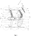
- Figure 1 shows a VTOL aircraft 1 having a fuselage or fuselage body 2 for transporting passengers and/or load.
- x, y, and z denote the aircraft axes (longitudinal, transverse, and vertical, respectively, as detailed above).
- a front wing 3 is attached to the fuselage 2.
- a rear wing 4 is attached to the fuselage 2 behind the front wing 3 in a direction of forward flight (arrow FF) of the aircraft 1.
- a right connecting beam 5a and a left connecting beam 5b structurally connect the front wing 3 and the rear wing 4, which connecting beams 5a, 5b are laterally spaced apart from the fuselage 2.
- the aircraft 1 comprises six lifting units M1-M6, three of which are arranged on each one of the connecting beams 5a, 5b.
- the lifting units M1-M6 each comprise at least one propeller 6b and at least one motor 6a driving said propeller 6b, preferably an electric motor, and they are arranged with their respective propeller axis in an essentially vertical orientation (z axis). This is explicitly shown for only one (M6) of the lifting units M1-M6 in Figure 1 .
- Reference numerals F1 and F2 denote forward propulsion units (pushers) that are attached at the right side and at the left side of the fuselage 2, respectively, toward the rear of the aircraft 1 (in front of rear wing 4).
- the pushers can comprise at least one propeller and at least one motor driving said propeller (not shown).
- Front wing 3 incorporates a dihedral angle ( ⁇ ) which, combined with the above-mentioned sweep angle ( ⁇ ⁇ 90°), positively affects lateral/directional stability of the aircraft 1.
- Said angle ⁇ may increase toward respective tips of the wing 3.
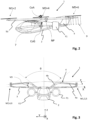
- the rear wing 4 incorporates an anhedral angle ( ⁇ ) in order to create a high vertical offset VO in the region of higher downwash 7 (cf. Figure 2 ) of the front wing 3 which occurs especially in the in-board portion of said wing 3 (spanwise).
- Said angle ⁇ too, may increase toward respective tips of the wing 4.
- the front wing 3 and the rear wing 4 when viewed along the longitudinal axis (x) of the aircraft 1, together form a closed loop shape.
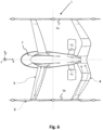
- Figure 5 is another front view of the aircraft 1 (cf. Figure 3 for additional details).
Landscapes
- Engineering & Computer Science (AREA)
- Aviation & Aerospace Engineering (AREA)
- Mechanical Engineering (AREA)
- Toys (AREA)
- Tires In General (AREA)
- Structures Of Non-Positive Displacement Pumps (AREA)
- Handcart (AREA)
Claims (12)
- Ein VTOL-Luftfahrzeug (1), umfassend:einen Rumpf (2) zur Beförderung von Passagieren und/oder Lasten;einen am Rumpf (2) befestigten vorderen Flügel (3);einen hinteren Flügel (4), der in Vorwärtsflugrichtung (FF) hinter dem vorderen Flügel (3) am Rumpf (2) befestigt ist;einen rechten Verbindungsträger (5a) und einen linken Verbindungsträger (5b), die den vorderen Flügel (3) und den hinteren Flügel (4) strukturell verbinden, wobei die Verbindungsträger (5a, 5b) vom Rumpf (2) beabstandet sind; undmindestens zwei Auftriebseinheiten (M1-M6) an jedem der Verbindungsträger (5a, 5b), wobei die Auftriebseinheiten (M1-M6) jeweils mindestens einen Propeller (6b) und mindestens einen Motor (6a), der den Propeller (6b) antreibt, vorzugsweise einen Elektromotor, umfassen, und die Propeller (6b) mit ihrer jeweiligen Propellerachse in einer im Wesentlichen vertikalen Ausrichtung (z) angeordnet sind;wobei der vordere Flügel (3) zumindest abschnittsweise einen Pfeilungswinkel y zwischen y = 45° und y = 135°, vorzugsweise y = 75°, aufweist und der hintere Flügel (4) zumindest abschnittsweise eine Vorwärtspfeilung mit Pfeilungswinkel β ≥ 30°, vorzugsweise β = 65°, aufweist,wobei der vordere Flügel (3) vorzugsweise an seinen jeweiligen Spitzen eine positive V-Stellung (λ) aufweist;wobei der hintere Flügel (4) zumindest in einem äußeren Teil einen eine negative V-Stellung (ε) zu den Verbindungsträgern (5a, 5b) hin aufweist;dadurch gekennzeichnet, dassder hintere Flügel (4) in vertikaler Position (z) höher angebracht ist als der vordere (3).
- Das Luftfahrzeug (1) nach Anspruch 1, wobei der vordere Flügel (3) eine Flügelfläche (Sfront) aufweist, die kleiner ist als eine Flügelfläche (Srear) des hinteren Flügels (4), vorzugsweise 60% < Sfront/Srear < 100%, mehr bevorzugt 60% < Sfront/Srear < 70%.
- Das Luftfahrzeug (1) nach Anspruch 1 oder 2, wobei
der hintere Flügel (4) teilweise in Form eines V-Schwanzes mit einem Pfeilungswinkel δ, δ > 90°, ausgebildet ist. - Das Luftfahrzeug (1) nach einem der Ansprüche 1 bis 3, wobei sich in einer Ebene senkrecht zu einer Längsachse (x) des Luftfahrzeugs (1) der hintere Flügel (4) seitlich vom Rumpf (2) erstreckt, so dass die jeweiligen Flügelhälften (4a, 4b) einen Winkel θ, θ < 180°, vorzugsweise etwa 90° bis 100° aufweisen.
- Das Luftfahrzeug (1) nach einem der Ansprüche 1 bis 4, umfassend drei Auftriebseinheiten (M1-M6) an jedem der Verbindungsträger (5a, 5b).
- Das Luftfahrzeug (1) nach einem der Ansprüche 1 bis 5, wobei die Auftriebseinheiten (M1-M6) symmetrisch um eine Längs- (x-z) bzw. eine Querebene (y-z) des Luftfahrzeugs (1) angeordnet sind.
- Das Luftfahrzeug (1) nach einem der Ansprüche 1 bis 6, wobei Befestigungen (A3, A4) des vorderen Flügels (3) und des hinteren Flügels (4) an den Verbindungsträgern (5a, 5b) jeweils zwischen den jeweiligen Rotorebenen (P1-P6), die von den Propellern (6b) aufgespannt werden, angeordnet sind.
- Das Luftfahrzeug (1) nach einem der Ansprüche 1 bis 7, wobei die Längsstabilität des Luftfahrzeugs, die durch die Größe Cm/α definiert ist, negativ ist, wobei Cm ein Nickmomentkoeffizient und α ein Anstellwinkel ist.
- Das Luftfahrzeug (1) nach einem der Ansprüche 1 bis 8, wobei ein Kraftangriffspunkt (CoA) geometrisch in der gleichen Längsposition (xcoA) liegt wie der Schwerpunkt des Luftfahrzeugs (CoG), während ein neutraler Punkt (NP) sowohl hinter dem Kraftangriffspunkt (CoA) als auch hinter dem Schwerpunkt (CoG) liegt.
- Das Luftfahrzeug (1) nach einem der Ansprüche 1 bis 9, ferner umfassend mindestens eine Vortriebseinheit (F1, F2), die vorzugsweise mindestens einen Propeller und mindestens einen Motor, der den Propeller antreibt, umfasst, vorzugsweise einen Elektromotor, der sich besonders bevorzugt im hinteren Teil des Luftfahrzeugs (1) befindet.
- Das Luftfahrzeug (1) nach Anspruch 10, wobei
zumindest eine Vortriebseinheit (F1, F2) auf jeder Seite des Rumpfes (2), vorzugsweise unter dem vorderen Flügel (3) und dem hinteren Flügel (4), und besonders bevorzugt vor dem hinteren Flügel (4), angeordnet ist. - Das Luftfahrzeug (1) nach einem der Ansprüche 1 bis 11, wobei der vordere Flügel (3) und der hintere Flügel (4), entlang einer Längsachse (x) des Flugzeugs (1) gesehen, zusammen eine geschlossene Schleifenform bilden.
Priority Applications (3)
| Application Number | Priority Date | Filing Date | Title |
|---|---|---|---|
| EP21161173.6A EP4056471B1 (de) | 2021-03-08 | 2021-03-08 | Senkrechtstart- und -landeflugzeug |
| US17/591,811 US12049307B2 (en) | 2021-03-08 | 2022-02-03 | VTOL aircraft with electric propulsion |
| CN202210219767.8A CN115042968B (zh) | 2021-03-08 | 2022-03-08 | 垂直起降飞机 |
Applications Claiming Priority (1)
| Application Number | Priority Date | Filing Date | Title |
|---|---|---|---|
| EP21161173.6A EP4056471B1 (de) | 2021-03-08 | 2021-03-08 | Senkrechtstart- und -landeflugzeug |
Publications (2)
| Publication Number | Publication Date |
|---|---|
| EP4056471A1 EP4056471A1 (de) | 2022-09-14 |
| EP4056471B1 true EP4056471B1 (de) | 2025-09-17 |
Family
ID=74859752
Family Applications (1)
| Application Number | Title | Priority Date | Filing Date |
|---|---|---|---|
| EP21161173.6A Active EP4056471B1 (de) | 2021-03-08 | 2021-03-08 | Senkrechtstart- und -landeflugzeug |
Country Status (3)
| Country | Link |
|---|---|
| US (1) | US12049307B2 (de) |
| EP (1) | EP4056471B1 (de) |
| CN (1) | CN115042968B (de) |
Families Citing this family (11)
| Publication number | Priority date | Publication date | Assignee | Title |
|---|---|---|---|---|
| TR202022599A1 (tr) * | 2020-12-31 | 2022-07-21 | Tusas Tuerk Havacilik Ve Uzay Sanayii Anonim Sirketi | Bir helikopter |
| US12559232B2 (en) * | 2021-05-31 | 2026-02-24 | Ampaire Inc. | Electric vertical takeoff and landing aircraft |
| US11634232B1 (en) * | 2022-04-30 | 2023-04-25 | Beta Air, Llc | Hybrid propulsion systems for an electric aircraft |
| US12195192B2 (en) * | 2022-04-30 | 2025-01-14 | Beta Air Llc | Hybrid propulsion systems for an electric aircraft |
| US11639230B1 (en) * | 2022-04-30 | 2023-05-02 | Beta Air, Llc | System for an integral hybrid electric aircraft |
| FI130682B1 (en) * | 2022-07-11 | 2024-01-16 | Raimo Hirvinen | Rocket stage, rocket and landing gear |
| US20240228036A9 (en) * | 2022-10-24 | 2024-07-11 | Textron Aviation Inc. | Electric Aircraft |
| JP2024176151A (ja) | 2023-06-08 | 2024-12-19 | 国立研究開発法人宇宙航空研究開発機構 | 垂直離着陸機 |
| US12139253B1 (en) * | 2023-09-07 | 2024-11-12 | Textron Eaviation Inc. | Tiltrotor aircraft control system |
| CN117382877A (zh) * | 2023-11-13 | 2024-01-12 | 中国直升机设计研究所 | 一种集装箱式eVTOL旋翼飞行器及eVTOL旋翼飞行器集群 |
| DE102023135708A1 (de) * | 2023-12-19 | 2025-06-26 | Volocopter Gmbh | Luftfahrzeug |
Citations (1)
| Publication number | Priority date | Publication date | Assignee | Title |
|---|---|---|---|---|
| EP3702276A1 (de) * | 2019-02-27 | 2020-09-02 | AIRBUS HELICOPTERS DEUTSCHLAND GmbH | Boxwing flugzeug mit mehreren rotoren mit fähigkeit zum senkrechten starten und landen (vtol) |
Family Cites Families (21)
| Publication number | Priority date | Publication date | Assignee | Title |
|---|---|---|---|---|
| US3834654A (en) | 1973-03-19 | 1974-09-10 | Lockheed Aircraft Corp | Boxplane wing and aircraft |
| USD311720S (en) | 1988-11-14 | 1990-10-30 | Butler Gerald L | Aircraft |
| DE19947633A1 (de) * | 1998-10-02 | 2000-09-28 | Andreas Lebelt | W-WING, W-Form-Haupttragfläche für Flugzeuge |
| US7159817B2 (en) * | 2005-01-13 | 2007-01-09 | Vandermey Timothy | Vertical take-off and landing (VTOL) aircraft with distributed thrust and control |
| US9545993B2 (en) * | 2007-01-12 | 2017-01-17 | John William McGinnis | Aircraft stability and efficient control through induced drag reduction |
| US9499266B1 (en) | 2014-06-24 | 2016-11-22 | Elytron Aircraft LLC | Five-wing aircraft to permit smooth transitions between vertical and horizontal flight |
| RU2608122C1 (ru) * | 2016-02-17 | 2017-01-13 | Дмитрий Сергеевич Дуров | Тяжелый скоростной винтокрыл |
| US9764833B1 (en) | 2016-10-18 | 2017-09-19 | Kitty Hawk Corporation | Ventilated rotor mounting boom for personal aircraft |
| US20180273170A1 (en) * | 2017-03-21 | 2018-09-27 | Regents Of The University Of Minnesota | Transformable unmanned aerial vehicle |
| US10577091B2 (en) * | 2017-04-24 | 2020-03-03 | Bcg Digital Ventures Gmbh | Vertical take-off and landing aircraft |
| US10081436B1 (en) | 2017-07-06 | 2018-09-25 | Autoflightx International Limited | Hybrid VTOL fixed-wing drone |
| RU180474U1 (ru) * | 2017-10-26 | 2018-06-14 | Федеральное государственное унитарное предприятие "Сибирский научно-исследовательский институт авиации им. С.А. Чаплыгина" | Самолёт вертикального взлёта и посадки |
| EP3837164B1 (de) * | 2018-08-19 | 2025-03-26 | Hernadi, Andras | Verfahren für verbesserungen des geschlossenen flügelkonzepts eines flugzeugs und entsprechende flugzeugkonfigurationen |
| US20200290725A1 (en) * | 2018-09-21 | 2020-09-17 | Bell Textron Inc. | Ducted thrusters |
| GB2583332A (en) * | 2019-04-09 | 2020-10-28 | Airbus Operations Ltd | Aircraft wing |
| CN110182361B (zh) * | 2019-05-28 | 2022-09-27 | 湖北电鹰科技有限公司 | 一种可倾转的垂直起降固定翼无人机 |
| CN114126966A (zh) * | 2019-05-29 | 2022-03-01 | 工艺航空航天技术股份有限公司 | 使用串联式机翼和分布式推进系统的新型飞行器设计 |
| EP3757004B1 (de) | 2019-06-27 | 2023-03-29 | Volocopter GmbH | Luftfahrzeug mit flügelverbindenden auslegern |
| GB2585864B (en) * | 2019-07-18 | 2022-04-27 | Gkn Aerospace Services Ltd | An aircraft |
| GB201913668D0 (en) * | 2019-07-30 | 2019-11-06 | Rolls Royce Plc | Lift rotor system |
| CN111086632A (zh) * | 2020-02-10 | 2020-05-01 | 廊坊希达电子科技有限公司 | 一种电动垂直起降无人机 |
-
2021
- 2021-03-08 EP EP21161173.6A patent/EP4056471B1/de active Active
-
2022
- 2022-02-03 US US17/591,811 patent/US12049307B2/en active Active
- 2022-03-08 CN CN202210219767.8A patent/CN115042968B/zh active Active
Patent Citations (1)
| Publication number | Priority date | Publication date | Assignee | Title |
|---|---|---|---|---|
| EP3702276A1 (de) * | 2019-02-27 | 2020-09-02 | AIRBUS HELICOPTERS DEUTSCHLAND GmbH | Boxwing flugzeug mit mehreren rotoren mit fähigkeit zum senkrechten starten und landen (vtol) |
Also Published As
| Publication number | Publication date |
|---|---|
| EP4056471A1 (de) | 2022-09-14 |
| CN115042968B (zh) | 2025-07-04 |
| CN115042968A (zh) | 2022-09-13 |
| US12049307B2 (en) | 2024-07-30 |
| US20220281593A1 (en) | 2022-09-08 |
Similar Documents
| Publication | Publication Date | Title |
|---|---|---|
| EP4056471B1 (de) | Senkrechtstart- und -landeflugzeug | |
| CN111619785B (zh) | 适于垂直起飞和着陆的多旋翼飞行器 | |
| CN112141328B (zh) | 飞机 | |
| US6592073B1 (en) | Amphibious aircraft | |
| US5086993A (en) | Airplane with variable-incidence wing | |
| KR102758509B1 (ko) | 테일 시터 | |
| EP2265495B1 (de) | Luftfahrzeug mit koaxialen rotoren | |
| EP2595882B1 (de) | Personenflugzeug | |
| EP2421752B1 (de) | Flugzeug mit integriertem hebe- und antriebssystem | |
| KR102680619B1 (ko) | 테일 시터 | |
| EP3705401A1 (de) | Montage von drei verbundflügeln für luft-, wasser-, land- oder raumfahrzeuge | |
| CN108082466A (zh) | 一种倾转涵道连接翼布局垂直起降飞行器 | |
| CN114026022A (zh) | 具有后旋翼和t型尾翼的固定翼飞机 | |
| CN101875399A (zh) | 一种采用并列式共轴双旋翼的倾转旋翼飞机 | |
| USRE36487E (en) | Airplane with variable-incidence wing | |
| CN106218887A (zh) | 一种分布式动力装置布局的垂直起降飞行器 | |
| CN111846199B (zh) | 具有稳定翼的旋翼飞行器 | |
| US20240359791A1 (en) | Aircraft | |
| CN116635298A (zh) | 具机身和机翼集成在气动翼型中的垂直起降飞行器 | |
| US20060016931A1 (en) | High-lift, low-drag dual fuselage aircraft | |
| US20020047069A1 (en) | Directional control and aerofoil system for aircraft | |
| Kentfield | Case for aircraft with outboard horizontal stabilizers | |
| US10654556B2 (en) | VTOL aircraft with wings | |
| RU2838699C1 (ru) | Беспилотный летательный аппарат | |
| RU2655249C1 (ru) | Скоростной вертолет-самолет-амфибия |
Legal Events
| Date | Code | Title | Description |
|---|---|---|---|
| PUAI | Public reference made under article 153(3) epc to a published international application that has entered the european phase |
Free format text: ORIGINAL CODE: 0009012 |
|
| STAA | Information on the status of an ep patent application or granted ep patent |
Free format text: STATUS: THE APPLICATION HAS BEEN PUBLISHED |
|
| AK | Designated contracting states |
Kind code of ref document: A1 Designated state(s): AL AT BE BG CH CY CZ DE DK EE ES FI FR GB GR HR HU IE IS IT LI LT LU LV MC MK MT NL NO PL PT RO RS SE SI SK SM TR |
|
| STAA | Information on the status of an ep patent application or granted ep patent |
Free format text: STATUS: REQUEST FOR EXAMINATION WAS MADE |
|
| 17P | Request for examination filed |
Effective date: 20221007 |
|
| RBV | Designated contracting states (corrected) |
Designated state(s): AL AT BE BG CH CY CZ DE DK EE ES FI FR GB GR HR HU IE IS IT LI LT LU LV MC MK MT NL NO PL PT RO RS SE SI SK SM TR |
|
| STAA | Information on the status of an ep patent application or granted ep patent |
Free format text: STATUS: EXAMINATION IS IN PROGRESS |
|
| 17Q | First examination report despatched |
Effective date: 20230728 |
|
| RAP3 | Party data changed (applicant data changed or rights of an application transferred) |
Owner name: VOLOCOPTER GMBH |
|
| GRAP | Despatch of communication of intention to grant a patent |
Free format text: ORIGINAL CODE: EPIDOSNIGR1 |
|
| STAA | Information on the status of an ep patent application or granted ep patent |
Free format text: STATUS: GRANT OF PATENT IS INTENDED |
|
| INTG | Intention to grant announced |
Effective date: 20241022 |
|
| GRAS | Grant fee paid |
Free format text: ORIGINAL CODE: EPIDOSNIGR3 |
|
| GRAA | (expected) grant |
Free format text: ORIGINAL CODE: 0009210 |
|
| STAA | Information on the status of an ep patent application or granted ep patent |
Free format text: STATUS: THE PATENT HAS BEEN GRANTED |
|
| AK | Designated contracting states |
Kind code of ref document: B1 Designated state(s): AL AT BE BG CH CY CZ DE DK EE ES FI FR GB GR HR HU IE IS IT LI LT LU LV MC MK MT NL NO PL PT RO RS SE SI SK SM TR |
|
| REG | Reference to a national code |
Ref country code: CH Ref legal event code: EP Ref country code: GB Ref legal event code: FG4D |
|
| REG | Reference to a national code |
Ref country code: DE Ref legal event code: R096 Ref document number: 602021029858 Country of ref document: DE |
|
| PUAC | Information related to the publication of a b1 document modified or deleted |
Free format text: ORIGINAL CODE: 0009299EPPU |
|
| STAA | Information on the status of an ep patent application or granted ep patent |
Free format text: STATUS: GRANT OF PATENT IS INTENDED |
|
| REG | Reference to a national code |
Ref country code: IE Ref legal event code: FG4D |
|
| REG | Reference to a national code |
Ref country code: CH Ref legal event code: PK Free format text: DIE ERTEILUNG WURDE VOM EPA WIDERRUFEN. |
|
| P01 | Opt-out of the competence of the unified patent court (upc) registered |
Free format text: CASE NUMBER: APP_19568/2025 Effective date: 20250423 |
|
| 29U | Proceedings interrupted after grant according to rule 142 epc |
Effective date: 20250301 |
|
| 29W | Proceedings resumed after grant [after interruption of proceedings according to rule 142 epc] |
Effective date: 20250801 |
|
| DB1 | Publication of patent cancelled |
Effective date: 20250516 |
|
| REG | Reference to a national code |
Ref country code: DE Ref legal event code: R107 Ref country code: DE Ref legal event code: R107 Ref document number: 602021029858 Country of ref document: DE |
|
| REG | Reference to a national code |
Ref country code: AT Ref legal event code: REZ Ref document number: 1789849 Country of ref document: AT Kind code of ref document: T Effective date: 20250430 |
|
| GRAA | (expected) grant |
Free format text: ORIGINAL CODE: 0009210 |
|
| STAA | Information on the status of an ep patent application or granted ep patent |
Free format text: STATUS: THE PATENT HAS BEEN GRANTED |
|
| REG | Reference to a national code |
Ref country code: DE Ref legal event code: R081 Ref document number: 602021029858 Country of ref document: DE Owner name: VOLOCOPTER TECHNOLOGIES GMBH, DE Free format text: FORMER OWNER: ANMELDERANGABEN UNKLAR / UNVOLLSTAENDIG, 80297 MUENCHEN, DE |
|
| RAP3 | Party data changed (applicant data changed or rights of an application transferred) |
Owner name: VOLOCOPTER TECHNOLOGIES GMBH |
|
| AK | Designated contracting states |
Kind code of ref document: B1 Designated state(s): AL AT BE BG CH CY CZ DE DK EE ES FI FR GB GR HR HU IE IS IT LI LT LU LV MC MK MT NL NO PL PT RO RS SE SI SK SM TR |
|
| REG | Reference to a national code |
Ref country code: CH Ref legal event code: EP |
|
| REG | Reference to a national code |
Ref country code: DE Ref legal event code: R096 Ref document number: 602021029858 Country of ref document: DE |
|
| PG25 | Lapsed in a contracting state [announced via postgrant information from national office to epo] |
Ref country code: PL Free format text: LAPSE BECAUSE OF FAILURE TO SUBMIT A TRANSLATION OF THE DESCRIPTION OR TO PAY THE FEE WITHIN THE PRESCRIBED TIME-LIMIT Effective date: 20250917 |
|
| PG25 | Lapsed in a contracting state [announced via postgrant information from national office to epo] |
Ref country code: NO Free format text: LAPSE BECAUSE OF FAILURE TO SUBMIT A TRANSLATION OF THE DESCRIPTION OR TO PAY THE FEE WITHIN THE PRESCRIBED TIME-LIMIT Effective date: 20251217 |
|
| REG | Reference to a national code |
Ref country code: LT Ref legal event code: MG9D |
|
| PG25 | Lapsed in a contracting state [announced via postgrant information from national office to epo] |
Ref country code: FI Free format text: LAPSE BECAUSE OF FAILURE TO SUBMIT A TRANSLATION OF THE DESCRIPTION OR TO PAY THE FEE WITHIN THE PRESCRIBED TIME-LIMIT Effective date: 20250917 |
|
| PG25 | Lapsed in a contracting state [announced via postgrant information from national office to epo] |
Ref country code: HR Free format text: LAPSE BECAUSE OF FAILURE TO SUBMIT A TRANSLATION OF THE DESCRIPTION OR TO PAY THE FEE WITHIN THE PRESCRIBED TIME-LIMIT Effective date: 20250917 |
|
| REG | Reference to a national code |
Ref country code: NL Ref legal event code: MP Effective date: 20250917 |
|
| PG25 | Lapsed in a contracting state [announced via postgrant information from national office to epo] |
Ref country code: LV Free format text: LAPSE BECAUSE OF FAILURE TO SUBMIT A TRANSLATION OF THE DESCRIPTION OR TO PAY THE FEE WITHIN THE PRESCRIBED TIME-LIMIT Effective date: 20250917 |
|
| PG25 | Lapsed in a contracting state [announced via postgrant information from national office to epo] |
Ref country code: BG Free format text: LAPSE BECAUSE OF FAILURE TO SUBMIT A TRANSLATION OF THE DESCRIPTION OR TO PAY THE FEE WITHIN THE PRESCRIBED TIME-LIMIT Effective date: 20250917 |
|
| PG25 | Lapsed in a contracting state [announced via postgrant information from national office to epo] |
Ref country code: NL Free format text: LAPSE BECAUSE OF FAILURE TO SUBMIT A TRANSLATION OF THE DESCRIPTION OR TO PAY THE FEE WITHIN THE PRESCRIBED TIME-LIMIT Effective date: 20250917 |
|
| REG | Reference to a national code |
Ref country code: AT Ref legal event code: MK05 Ref document number: 1789849 Country of ref document: AT Kind code of ref document: T Effective date: 20250917 |