EP4056471A1 - Vtol aircraft - Google Patents
Vtol aircraft Download PDFInfo
- Publication number
- EP4056471A1 EP4056471A1 EP21161173.6A EP21161173A EP4056471A1 EP 4056471 A1 EP4056471 A1 EP 4056471A1 EP 21161173 A EP21161173 A EP 21161173A EP 4056471 A1 EP4056471 A1 EP 4056471A1
- Authority
- EP
- European Patent Office
- Prior art keywords
- aircraft
- wing
- fuselage
- angle
- rear wing
- Prior art date
- Legal status (The legal status is an assumption and is not a legal conclusion. Google has not performed a legal analysis and makes no representation as to the accuracy of the status listed.)
- Granted
Links
Images


Classifications
-
- B—PERFORMING OPERATIONS; TRANSPORTING
- B64—AIRCRAFT; AVIATION; COSMONAUTICS
- B64C—AEROPLANES; HELICOPTERS
- B64C39/00—Aircraft not otherwise provided for
- B64C39/12—Canard-type aircraft
-
- B—PERFORMING OPERATIONS; TRANSPORTING
- B64—AIRCRAFT; AVIATION; COSMONAUTICS
- B64C—AEROPLANES; HELICOPTERS
- B64C27/00—Rotorcraft; Rotors peculiar thereto
- B64C27/22—Compound rotorcraft, i.e. aircraft using in flight the features of both aeroplane and rotorcraft
-
- B—PERFORMING OPERATIONS; TRANSPORTING
- B64—AIRCRAFT; AVIATION; COSMONAUTICS
- B64C—AEROPLANES; HELICOPTERS
- B64C27/00—Rotorcraft; Rotors peculiar thereto
- B64C27/22—Compound rotorcraft, i.e. aircraft using in flight the features of both aeroplane and rotorcraft
- B64C27/26—Compound rotorcraft, i.e. aircraft using in flight the features of both aeroplane and rotorcraft characterised by provision of fixed wings
-
- B—PERFORMING OPERATIONS; TRANSPORTING
- B64—AIRCRAFT; AVIATION; COSMONAUTICS
- B64C—AEROPLANES; HELICOPTERS
- B64C29/00—Aircraft capable of landing or taking-off vertically, e.g. vertical take-off and landing [VTOL] aircraft
- B64C29/0008—Aircraft capable of landing or taking-off vertically, e.g. vertical take-off and landing [VTOL] aircraft having its flight directional axis horizontal when grounded
- B64C29/0016—Aircraft capable of landing or taking-off vertically, e.g. vertical take-off and landing [VTOL] aircraft having its flight directional axis horizontal when grounded the lift during taking-off being created by free or ducted propellers or by blowers
- B64C29/0025—Aircraft capable of landing or taking-off vertically, e.g. vertical take-off and landing [VTOL] aircraft having its flight directional axis horizontal when grounded the lift during taking-off being created by free or ducted propellers or by blowers the propellers being fixed relative to the fuselage
-
- B—PERFORMING OPERATIONS; TRANSPORTING
- B64—AIRCRAFT; AVIATION; COSMONAUTICS
- B64C—AEROPLANES; HELICOPTERS
- B64C29/00—Aircraft capable of landing or taking-off vertically, e.g. vertical take-off and landing [VTOL] aircraft
- B64C29/02—Aircraft capable of landing or taking-off vertically, e.g. vertical take-off and landing [VTOL] aircraft having its flight directional axis vertical when grounded
-
- B—PERFORMING OPERATIONS; TRANSPORTING
- B64—AIRCRAFT; AVIATION; COSMONAUTICS
- B64C—AEROPLANES; HELICOPTERS
- B64C3/00—Wings
- B64C3/10—Shape of wings
- B64C3/16—Frontal aspect
-
- B—PERFORMING OPERATIONS; TRANSPORTING
- B64—AIRCRAFT; AVIATION; COSMONAUTICS
- B64C—AEROPLANES; HELICOPTERS
- B64C3/00—Wings
- B64C3/32—Wings specially adapted for mounting power plant
-
- B—PERFORMING OPERATIONS; TRANSPORTING
- B64—AIRCRAFT; AVIATION; COSMONAUTICS
- B64C—AEROPLANES; HELICOPTERS
- B64C39/00—Aircraft not otherwise provided for
- B64C39/06—Aircraft not otherwise provided for having disc- or ring-shaped wings
- B64C39/068—Aircraft not otherwise provided for having disc- or ring-shaped wings having multiple wings joined at the tips
-
- B—PERFORMING OPERATIONS; TRANSPORTING
- B64—AIRCRAFT; AVIATION; COSMONAUTICS
- B64D—EQUIPMENT FOR FITTING IN OR TO AIRCRAFT; FLIGHT SUITS; PARACHUTES; ARRANGEMENT OR MOUNTING OF POWER PLANTS OR PROPULSION TRANSMISSIONS IN AIRCRAFT
- B64D27/00—Arrangement or mounting of power plants in aircraft; Aircraft characterised by the type or position of power plants
- B64D27/02—Aircraft characterised by the type or position of power plants
- B64D27/30—Aircraft characterised by electric power plants
- B64D27/31—Aircraft characterised by electric power plants within, or attached to, wings
-
- B—PERFORMING OPERATIONS; TRANSPORTING
- B64—AIRCRAFT; AVIATION; COSMONAUTICS
- B64D—EQUIPMENT FOR FITTING IN OR TO AIRCRAFT; FLIGHT SUITS; PARACHUTES; ARRANGEMENT OR MOUNTING OF POWER PLANTS OR PROPULSION TRANSMISSIONS IN AIRCRAFT
- B64D27/00—Arrangement or mounting of power plants in aircraft; Aircraft characterised by the type or position of power plants
- B64D27/02—Aircraft characterised by the type or position of power plants
- B64D27/30—Aircraft characterised by electric power plants
- B64D27/34—All-electric aircraft
Definitions
- the invention relates to a vertical take-off and landing (VTOL) aircraft according to appended claim 1, in particular with electrically powered propulsion or lifting units, i.e., a so-called eVTOL aircraft.
- VTOL vertical take-off and landing
- the Pipistrel Nuuva V300 is an unmanned cargodrone, the main weight of which is centrally located, meaning that the wing surface distribution is essentially symmetrical about the y-z plane. It has a tandem wing and eight lifting propellers. A drawback is that the landing loads (similar to the Boeing/Aurora PAV) are transferred over the engine nacelles which is unfavourable.
- the known designs lack a structurally integrated aircraft architecture that leads to high weight penalties or an aircraft with a low payload empty weight ratio.
- a “swept wing” is a wing that angles either backward or forward from its root rather than in a straight sideways (90°) direction.
- the term “swept wing” is normally used to mean “swept back”, but variants include forward sweep, variable sweep wings and oblique wings in which one side sweeps forward and the other back.
- sweep angles ⁇ 90° indicate a forward sweep, i.e., the wings angle forward in the direction of (forward) flight.
- ⁇ 75°.
- ⁇ 65°.
- the connecting beams are preferably placed higher than (or above) the fuselage in a side view of the aircraft for better accessibility.
- the present invention may comprise putting the following physically definable points (which are well known to a skilled person in the field of aviation) in a specific place in order to create a transition aircraft with good aeromechanical characteristics while having performant multicopter characteristics, especially in the case of one-engine-inoperative (OEI).
- OEI one-engine-inoperative
- the present invention proposes to find a technical solution in order to bring the Center of Gravity, the Center of Actuation, and the Neutral Point as close as possible to each other during the flight phases of hovering over the transition towards airplane mode, and vice versa.
- the aircraft's layout is preferably designed in such a manner that the longitudinal stability, which is defined by Cm/a, is negative (i.e., Cm/a ⁇ 0).
- aircraft As any aircraft moves, it will be subjected to minor changes in the forces that act on it, and in its speed. If such a change causes further changes that tend to restore the aircraft to its original speed and orientation, without human or machine input, the aircraft is said to be statically stable. Such aircraft has positive stability. On the other hand, if such a change causes further changes that tend to drive the aircraft away from its original speed and orientation, the aircraft is said to be statically unstable. Such aircraft has negative stability. As known to the skilled person, aircraft can have a form of low-negative stability called relaxed stability to provide extra-high manoeuvrability.
- the invention may comprise to choose the lifting units' coordinate positions in such a way that they are arranged essentially symmetrical in terms of the aircraft's geometry thus defining a CoA which is geometrically, at least approximately, in the same x-position as the CoG while the NP is designed to be aft of these two points (CoA, CoG).
- these axes are also represented by the letters x, y, and z, respectively.
- the invention may also comprise a specific balancing of the aircraft's wing surface size (or area) between front wing and rear wing as this defines the longitudinal stability of the aircraft.
- the above-mentioned forward sweep of these wings pushes the aircraft's neutral point (NP) as far as possible to the aft.
- a centre of actuation of the aircraft is geometrically in the same longitudinal position as the aircraft's centre of gravity, while a neutral point is located aft of both the centre of actuation and the centre of gravity.
- said front and rear wings have the necessary size (area) in order to create the lift needed to carry the weight of entire aircraft.
- the front and rear wings may have an unequal planform size of 40% in the front and 60% in the rear, yet the produced lift can have the opposite ratio, with 60% for the front wing and 40% for the rear wing.
- the rear wing may be split into two separate, yet structurally connected parts, i.e., an aircraft lifting part (wing) and a stabilizing unit (e.g., in the form of a so-called V-Tail) which is not strongly contributing to the aircraft's lift, yet provides a significant horizontal surface acting as a wind vane contributing to the lateral stability.
- the front wing has a wing area S front that is smaller than a wing area S rear of the rear wing, preferably 60% ⁇ S front /S rear ⁇ 100%, more preferably 60% ⁇ S front /S rear ⁇ 70%.
- the rear wing extends sideways from the fuselage in a plane perpendicular to a longitudinal axis (x) of the aircraft, such that respective wing halves form an angle ( ⁇ ) ⁇ 180°, preferably approximately 90° to 100°.
- wing attachments can be placed in between the rotor planes. Said rotor planes can be defined as respective areas swept by the rotating propellers. This leads to improved rotor performances during hovering or low speed manoeuvres.
- the rear wing Due to the presence of a front wing, the rear wing is typically negatively affected in terms of aerodynamics as the front wing induces an airflow impinging the rear wing. In order to reduce this effect, in a corresponding embodiment of the aircraft according to the invention the rear wing can be placed higher in vertical position. However, it can still be connected to the connecting beams. Generally speaking, this feature may lead to a rigid airframe design from body (fuselage) to wing and from wing to lifting unit.
- any torsion occurring in the wing can be significantly reduced. This is beneficial as loads are balanced and routed.
- the aircraft's lifting units can be placed essentially symmetrical about the aircraft longitudinal (x) and lateral (y) axis. In this way, coupling in the multicopter mode is minimized and performance during the OEI mode is improved, as the respective geometrical distances from every one of the lifting units to the centre of gravity are essentially the same.
- the lifting units are thus placed symmetrically about a longitudinal and a lateral axis, respectively, of the aircraft.
- the aircraft comprises three lifting units on each one of the connecting beams.
- the static lift units i.e., wings
- the static lift units can be efficiently connected to the structural or connecting beams at a (longitudinal) position that is located between each rotating lift unit's rotation disc or rotor plane (i.e., an area swept by the respective propellers).
- attachments of the front wing and the rear wing, respectively, to the connecting beams are placed in between respective rotor planes swept by the propellers, so that there is no overlap in vertical direction between the propellers and said attachments.
- the aircraft according to the invention has a front wing and a rear wing which together define the aircraft's neutral point (NP).
- the NP is mainly defined by the combination of the respective aerodynamic centres (CA) of the aircraft wings.
- CA front for the front wing and CA rear for the rear wing The distance of each aerodynamic centre (CA front for the front wing and CA rear for the rear wing) multiplied with the respective longitudinal distance x to the aircraft's centre of gravity (CoG) defines a longitudinal momentum.
- Cm/a can be chosen to be negative, hence leading to a stable aircraft.
- longitudinal static stability is achieved by distributing the horizontal surface areas of a aircraft in such a way that a pitch deviation induces a counteracting pitch moment.
- All horizontal surface area aft of the CoG contributes positively to the longitudinal static stability by the wind vane effect.
- All horizontal surface area in front of the CoG destabilizes. Each horizontal surface area contributes to this effect with its respective area multiplied with the lever arm from its center of area to the CoG.
- the Neutral Point (NP) of the aircraft is defined as the point where all pitching moments are in equilibrium. To achieve longitudinal static stability, said Neutral Point needs to be aft of CoG. This geometry leads to Cm/a ⁇ 0.
- Typical state of the art aircraft wings may be connected to the fuselage in an essentially lateral angle (90°), leading to a straight wing (no sweep). Following this principle will lead to a resulting neutral point which is positioned relatively far forward, hence creating an unstable longitudinal stability.
- the front wing incorporates a sweep angle ⁇ , being less than 90°
- the rear wing incorporates a sweep angle of ⁇ , also being less than 90°.
- the front wing has a wing area S front that is smaller than a wing area S rear of the rear wing, whereas the rear wing surfaces may produce less vertical lift due to the presence of a V-Tail.
- the V-Tail may incorporate a sweep angle ⁇ greater than 90°. This also leads to an improved load transfer into the fuselage body.
- the rear wing is partly shaped in the form of a V-Tail with a sweep angle ( ⁇ ) greater than 90°.
- the front wing may incorporate a dihedral angle ( ⁇ ) which, combined with the above-mentioned sweep angle ( ⁇ ), positively affects the aircraft's lateral/directional stability.
- the front wing incorporates a dihedral angle ( ⁇ ), preferably at least at or increasing toward respective tips thereof, preferably 0° ⁇ ⁇ ⁇ 5°.
- the rear wing may incorporate an anhedral angle ( ⁇ ) in order to create a high vertical offset in the region of higher downwash of the front wing which occurs primarily in an in-board portion of the wing (spanwise).
- the rear wing therefore incorporates an anhedral angle ( ⁇ ), at least in and preferably increasing toward an outer portion thereof, i.e., towards said connecting beams, preferably 0° ⁇ ⁇ ⁇ 5°.
- dihedral is the angle between the left and right wings (or tail surfaces) of an aircraft. Particularly, a dihedral angle is the upward angle from horizontal of the wings or tailplane of a (fixed-wing) aircraft.
- Anhedral angle is the name given to a negative dihedral angle, that is, when there is a downward angle from horizontal of the wings or tailplane of a (fixed-wing) aircraft.
- said aircraft further comprises at least one forward propulsion unit, said forward propulsion unit preferably - and without limitation - having at least one propeller and at least one motor driving said propeller, preferably an electric motor, more preferably located toward the rear of the aircraft.
- Such forward propulsion unit is beneficial in forward flight.
- At least one forward propulsion unit is located on each side of the fuselage, preferably below both the front wing and the rear wing and most preferably forward of the rear wing. This has proved highly beneficial for reaching high forward flight velocities.
- the front wing and the rear wing when viewed along a longitudinal axis of the aircraft, together form a closed loop shape. This provides increased mechanical stability and reduces negative aerodynamic effects.
- Figure 1 shows a VTOL aircraft 1 having a fuselage or fuselage body 2 for transporting passengers and/or load.
- x, y, and z denote the aircraft axes (longitudinal, transverse, and vertical, respectively, as detailed above).
- a front wing 3 is attached to the fuselage 2.
- a rear wing 4 is attached to the fuselage 2 behind the front wing 3 in a direction of forward flight (arrow FF) of the aircraft 1.
- a right connecting beam 5a and a left connecting beam 5b structurally connect the front wing 3 and the rear wing 4, which connecting beams 5a, 5b are laterally spaced apart from the fuselage 2.
- the aircraft 1 comprises six lifting units M1-M6, three of which are arranged on each one of the connecting beams 5a, 5b.
- the lifting units M1-M6 each comprise at least one propeller 6b and at least one motor 6a driving said propeller 6b, preferably an electric motor, and they are arranged with their respective propeller axis in an essentially vertical orientation (z axis). This is explicitly shown for only one (M6) of the lifting units M1-M6 in Figure 1 .
- the lifting units M1-M6 are placed symmetrically about the longitudinal (x) and lateral (y) axes of the aircraft 1: Lifting units M1 and M5 are placed at equal distances (in x-direction) toward the front and the rear, respectively, when compared to lifting unit M3. The same holds for lifting units M2, M4, and M6. Furthermore, the three lifting units on each side of the aircraft 1 are placed at equal transverse distances (in y-direction) from the aircraft's longitudinal axis.
- Reference numerals P1-P6 denote rotor planes that can be defined as respective areas swept by the rotating propellers 6b of lifting units M1-M6. Wing attachments to the connecting beams 5a, 5b are be placed in between and outside the rotor planes P1-P6. Said wing attachments are denoted A3 for front wing 3 and A4 for rear wing 4.
- Rear wing 4 has a backward sweep (angle ⁇ ) in a region close to the fuselage 2 (V-Tail), which helps to reduce the length of the fuselage 2 while keeping a sufficient rear surface wing area S rear (cf. below).
- Reference numerals F1 and F2 denote forward propulsion units (pushers) that are attached at the right side and at the left side of the fuselage 2, respectively, toward the rear of the aircraft 1 (in front of rear wing 4).
- the pushers can comprise at least one propeller and at least one motor driving said propeller (not shown).
- the centre of actuation CoA of the aircraft 1 is geometrically in the same longitudinal position (x CoA ) as the aircraft's centre of gravity CoG (at least approximately), while the neutral point NP is located well aft of both the centre of actuation CoA and the centre of gravity CoG due to the forward sweep of wings 3 and 4.
- the front wing 3 has a wing area S front that is smaller than a wing area S rear of the rear wing 4.
- a wing area S rear of the rear wing 4 In the present example 60% ⁇ S front /S rear ⁇ 70%.
- the rear wing 4 comprises the surface of a V-Tail (wing half 4b) and a classical lifting wing surface (wing half 4a), which will become apparent from Figs. 3 to 5 below.
- Figure 2 shows a side view of the aircraft 1 of Figure 1 . Same elements are denoted by common reference numerals in all Figures.
- the connecting beams (only beam 5b is visible in Figure 2 ) are placed higher than (or above) the fuselage 2, i.e., in the z direction (cf. Figure 1 ).
- M1+2 denotes lifting units M1 and M2, which are located behind one another in the line of sight. Same applies to lifting units M3 and M4 as well as lifting units M5 and M6, respectively.
- Reference numeral D denotes propeller downwash (only shown for one (M5+6) of the lifting units M1-M6). Said wing attachments (cf. Figure 1 ) are located outside the downwash zones.
- Figure 3 shows a front view of the aircraft 1.
- the rear wing 4 extends sideways from the fuselage 2 such that respective wing halves 4a, 4b of rear wing 4 form an angle ⁇ ⁇ 180°, preferably approximately 90° to 100°.
- the inner wing half 4b forms the surface of a V-Tail, while the outer half 4a represents a classical lifting wing surface.
- Front wing 3 incorporates a dihedral angle ( ⁇ ) which, combined with the above-mentioned sweep angle ( ⁇ ⁇ 90°), positively affects lateral/directional stability of the aircraft 1.
- Said angle ⁇ may increase toward respective tips of the wing 3.
- the rear wing 4 incorporates an anhedral angle ( ⁇ ) in order to create a high vertical offset VO in the region of higher downwash 7 (cf. Figure 2 ) of the front wing 3 which occurs especially in the in-board portion of said wing 3 (spanwise).
- Said angle ⁇ too, may increase toward respective tips of the wing 4.
- the front wing 3 and the rear wing 4 when viewed along the longitudinal axis (x) of the aircraft 1, together form a closed loop shape.
- FIG 4 is a somewhat simplified version of Figure 1 for to illustrate the front wing 3 with its area S front being smaller than area S rear of the rear wing 4.
- the rear wing surfaces produce less vertical lift due to the V-Tail configuration.
- Rear wing 4 comprises the surface of the V-Tail 4b and classical lifting wing surface 4a, which are illustrated by means of different shadings.
- Figure 5 is another front view of the aircraft 1 (cf. Figure 3 for additional details).
Landscapes
- Engineering & Computer Science (AREA)
- Aviation & Aerospace Engineering (AREA)
- Mechanical Engineering (AREA)
- Toys (AREA)
- Structures Of Non-Positive Displacement Pumps (AREA)
- Tires In General (AREA)
- Handcart (AREA)
Abstract
Description
- The invention relates to a vertical take-off and landing (VTOL) aircraft according to appended
claim 1, in particular with electrically powered propulsion or lifting units, i.e., a so-called eVTOL aircraft. - Somewhat similar aircraft designs are disclosed, e.g., in
USD311720S US3834654A , andUS9499266B1 - Generally, contemporary eVTOL aircraft designs suffer from poor aerodynamic efficiency since they incorporate several systems in order to vertically lift the aircraft as well as to move it horizontally. In particular, none of the known designs can be regarded as naturally stable aircrafts. Examples for known designs comprise aircrafts by Zee Aero/Cora, cf.
US2018/105268A1 ; EmbraerX; Aurora FlightScience (now part of Boeing); CityAirbus & Project Zero; AutoflightX, cf.US10081436B1 - The Pipistrel Nuuva V300 is an unmanned cargodrone, the main weight of which is centrally located, meaning that the wing surface distribution is essentially symmetrical about the y-z plane. It has a tandem wing and eight lifting propellers. A drawback is that the landing loads (similar to the Boeing/Aurora PAV) are transferred over the engine nacelles which is unfavourable.
- None of the known designs achieves a comfortable passenger entry into the fuselage. All known designs lead to an unfavourable solution for passengers entering the aircraft. This is mainly due to the low vertical position of the propulsion and lifting system.
- Most known designs have high aerodynamical blockages (or installation losses) of aircraft parts within the lifting propeller airflow during hover/low-speed conditions (cf. UBER elevate crm003), which leads to high power losses during hover and transition flight.
- Most known designs have lifting propellers aft of each other. The greater the number, the higher the aerodynamic losses will be for the rear lying propellers, which leads to (an unnecessarily) high power consumption and thus increased overall aircraft weight or reduced travel range.
- Most known designs are not scalable in size and are already greater than 10 m in span with a relatively low amount of payload. Hence scaling up to higher payloads and/or passenger capacity will result in even bigger aircraft sizes. However, landing sites are limited in size, especially in urban areas, and with increasing size, weight will increase over-proportionally.
- Most known configurations have many, low diameter lifting propellers which have therefore a higher disk load which leads to an increased noise level.
- The known designs lack a structurally integrated aircraft architecture that leads to high weight penalties or an aircraft with a low payload empty weight ratio.
- In a previous application (
EP 3 757 004 A1 - However, in order to provide reliable everyday VTOL aircraft, there is additional need for an improved hybrid-type or transition aircraft (i.e., a multicopter + a winged aircraft) in order to
- increase aerodynamic efficiency and/or minimize drag, in particular to be aerodynamically efficient in terms of lift to drag ratio when using a multicopter tandem wing;
- be aerodynamically naturally stable as an aircraft, hence creating an overall aircraft momentum to stabilize the aircraft in its longitudinal axis. This is essential to fulfil certification requirements more easily and to improve the aircraft's overall flight efficiency;
- create an aircraft wing configuration which works equally well in multicopter and in airplane mode, taking into account that the acting forces and momenta of both rotating lift units (propellers) and static lift units (wings) vary strongly in each condition and may lead to unfavourable aeromechanical characteristics;
- cope with at least one engine or propeller failure, which implies respecting a specific centre of gravity location versus a location of the centre of actuation.
- It is the object of the invention to propose a novel VTOL aircraft design which provides further improvements over the design described in
EP 3 757 004 A1 - This object is achieved by means of a VTOL aircraft having the features defined in appended
claim 1. Advantageous further developments of such an aircraft are defined in the dependent claims. - According to the invention, a VTOL aircraft comprises: a fuselage for transporting passengers and/or load; a front wing attached to the fuselage; a rear wing attached to the fuselage, behind the front wing in a direction of forward flight; a right connecting beam and a left connecting beam, which connecting beams structurally connect the front wing and the rear wing, which connecting beams are spaced apart from the fuselage; and at least two lifting units on each one of the connecting beams, which lifting units each comprise at least one propeller and at least one motor driving said propeller, preferably an electric motor, and are arranged with their respective propeller axis in an essentially vertical orientation; wherein the front wing, at least in portions thereof, has a sweep angle γ between γ = 45° and γ = 135°, preferably γ = 75°, and the rear wing, at least in portions thereof, has a forward sweep (i.e., β < 90°) with sweep angle β ≥ 30°, preferably, β = 65°.
- A "swept wing" is a wing that angles either backward or forward from its root rather than in a straight sideways (90°) direction. The term "swept wing" is normally used to mean "swept back", but variants include forward sweep, variable sweep wings and oblique wings in which one side sweeps forward and the other back. In the present context, sweep angles < 90° indicate a forward sweep, i.e., the wings angle forward in the direction of (forward) flight.
- In the context of the invention, the sweep angle, γ, of the front wing can be comprised between γ = 45° and γ = 135°. Preferably, γ = 75°. The (forward) sweep angle, β, of the rear wing can be comprised between β = 30° and β = 90°. Preferably, β = 65°.
- The connecting beams are preferably placed higher than (or above) the fuselage in a side view of the aircraft for better accessibility.
- More generally, the present invention may comprise putting the following physically definable points (which are well known to a skilled person in the field of aviation) in a specific place in order to create a transition aircraft with good aeromechanical characteristics while having performant multicopter characteristics, especially in the case of one-engine-inoperative (OEI).
- Said points are defined as follows, and this terminology will be used below:
- Centre of Actuation (CoA) is the reference point defined by the positions and attitudes of the lifting rotors. CoA is typically equal to the geometric center of all the lifting rotors, yet mathematically the point where all lifting forces and moments are in equilibrium.
- Centre of Gravity (CoG) = the point where all gravity forces act if the aircraft is in equilibrium. In other words: In physics, the CoG or centre of mass of a distribution of mass in space (sometimes referred to as the balance point) is the unique point where the weighted relative position of the distributed mass sums to zero. This point is defined by the aircraft layout, geometry and weight distribution.
- Neutral Point (NP) = the point where, mathematically, all moments of any lifting surfaces (e.g., wings) acting upon the aircraft are zero. A mathematical analysis of the longitudinal static stability of a complete aircraft (including horizontal stabilizers) yields the position of centre of gravity at which stability is neutral. This position is called the neutral point. (The larger the area of any horizontal stabilizer, and the greater the moment arm of the horizontal stabilizer about the aerodynamic centre, the further aft is the neutral point.) A well-defined NP is key for a longitudinal stable aircraft and mainly defined by the static lifting units (e.g., wings, stabilizers).
- Aerodynamic centre (CA) = the point where all pitching moment (Cm) coefficients of a lifting body (e.g., wing) do not vary with angle of attack α (dCm/dα = 0). This point is primarily defined by the static lifting units (e.g., wings, stabilizers) in terms of planform, position, size, etc. More specifically, the torques or moments acting on an airfoil moving through a fluid can be accounted for by the net lift and net drag applied at some point on the airfoil, and a separate net pitching moment about that point, whose magnitude varies with the choice of where the lift is chosen to be applied. The CA is the point at which the pitching moment coefficient for the airfoil does not vary with lift coefficient (i.e., angle of attack), making analysis simpler.
- The present invention proposes to find a technical solution in order to bring the Center of Gravity, the Center of Actuation, and the Neutral Point as close as possible to each other during the flight phases of hovering over the transition towards airplane mode, and vice versa. Next to a low drag design and a structurally integrated airframe design, the aircraft's layout is preferably designed in such a manner that the longitudinal stability, which is defined by Cm/a, is negative (i.e., Cm/a < 0).
- As any aircraft moves, it will be subjected to minor changes in the forces that act on it, and in its speed. If such a change causes further changes that tend to restore the aircraft to its original speed and orientation, without human or machine input, the aircraft is said to be statically stable. Such aircraft has positive stability. On the other hand, if such a change causes further changes that tend to drive the aircraft away from its original speed and orientation, the aircraft is said to be statically unstable. Such aircraft has negative stability. As known to the skilled person, aircraft can have a form of low-negative stability called relaxed stability to provide extra-high manoeuvrability.
- The invention may comprise to choose the lifting units' coordinate positions in such a way that they are arranged essentially symmetrical in terms of the aircraft's geometry thus defining a CoA which is geometrically, at least approximately, in the same x-position as the CoG while the NP is designed to be aft of these two points (CoA, CoG).
- Typically, the principal axes of an aircraft are defined as
- Longitudinal axis, or roll axis - an axis drawn through the body of the aircraft from tail to nose in the normal direction of flight, or the direction the pilot faces, similar to a ship's waterline.
- Transverse axis, or lateral axis, or pitch axis - an axis running from the pilot's left to right in piloted aircraft, and parallel to the wings of a winged aircraft, parallel to the buttock line.
- Normal axis, or yaw axis - a vertical axis drawn from top to bottom, and perpendicular to the other two axes.
- Hereinafter, these axes are also represented by the letters x, y, and z, respectively.
- The invention may also comprise a specific balancing of the aircraft's wing surface size (or area) between front wing and rear wing as this defines the longitudinal stability of the aircraft. The above-mentioned forward sweep of these wings pushes the aircraft's neutral point (NP) as far as possible to the aft.
- In a corresponding embodiment of the aircraft according to the invention, a centre of actuation of the aircraft is geometrically in the same longitudinal position as the aircraft's centre of gravity, while a neutral point is located aft of both the centre of actuation and the centre of gravity.
- In total, said front and rear wings have the necessary size (area) in order to create the lift needed to carry the weight of entire aircraft.
- However, the front and rear wings may have an unequal planform size of 40% in the front and 60% in the rear, yet the produced lift can have the opposite ratio, with 60% for the front wing and 40% for the rear wing. In order to achieve this, the rear wing may be split into two separate, yet structurally connected parts, i.e., an aircraft lifting part (wing) and a stabilizing unit (e.g., in the form of a so-called V-Tail) which is not strongly contributing to the aircraft's lift, yet provides a significant horizontal surface acting as a wind vane contributing to the lateral stability.
- In a corresponding embodiment of the aircraft according to the invention, the front wing has a wing area Sfront that is smaller than a wing area Srear of the rear wing, preferably 60% < Sfront/Srear < 100%, more preferably 60% < Sfront/Srear < 70%.
- In another embodiment of the aircraft according to the invention, the rear wing extends sideways from the fuselage in a plane perpendicular to a longitudinal axis (x) of the aircraft, such that respective wing halves form an angle (θ) < 180°, preferably approximately 90° to 100°.
- In order to reduce the download effect of any rotating lifting unit (e.g., propellers), which is created if an airflow generated by the lifting unit impinges a solid material (e.g., the engine mounts), wing attachments can be placed in between the rotor planes. Said rotor planes can be defined as respective areas swept by the rotating propellers. This leads to improved rotor performances during hovering or low speed manoeuvres.
- Due to the presence of a front wing, the rear wing is typically negatively affected in terms of aerodynamics as the front wing induces an airflow impinging the rear wing. In order to reduce this effect, in a corresponding embodiment of the aircraft according to the invention the rear wing can be placed higher in vertical position. However, it can still be connected to the connecting beams. Generally speaking, this feature may lead to a rigid airframe design from body (fuselage) to wing and from wing to lifting unit.
- Due to the fact that the front and rear wings are structurally connected via the connecting beams, any torsion occurring in the wing can be significantly reduced. This is beneficial as loads are balanced and routed.
- As indicated above, the aircraft's lifting units can be placed essentially symmetrical about the aircraft longitudinal (x) and lateral (y) axis. In this way, coupling in the multicopter mode is minimized and performance during the OEI mode is improved, as the respective geometrical distances from every one of the lifting units to the centre of gravity are essentially the same.
- In a corresponding embodiment of the aircraft according to the invention, the lifting units are thus placed symmetrically about a longitudinal and a lateral axis, respectively, of the aircraft.
- As mentioned above, the positioning of the lifting units defines the centre of actuation (CoA) for the multicopter mode, which can be defined in terms of longitudinal position by

- In a corresponding embodiment of the aircraft according to the invention, the aircraft comprises three lifting units on each one of the connecting beams.
- This will also work for a quadcopter (n = 4) or for an octocopter (n = 8) or for any other coaxial configuration (with respect to the aircraft's longitudinal axis).
- In order to reduce the download effect from any (rotating) lifting units, the static lift units (i.e., wings) can be efficiently connected to the structural or connecting beams at a (longitudinal) position that is located between each rotating lift unit's rotation disc or rotor plane (i.e., an area swept by the respective propellers).
- In a corresponding embodiment of the aircraft according to the invention, attachments of the front wing and the rear wing, respectively, to the connecting beams are placed in between respective rotor planes swept by the propellers, so that there is no overlap in vertical direction between the propellers and said attachments.
- The aircraft according to the invention has a front wing and a rear wing which together define the aircraft's neutral point (NP). As known to the skilled person, the NP is mainly defined by the combination of the respective aerodynamic centres (CA) of the aircraft wings. The distance of each aerodynamic centre (CAfront for the front wing and CArear for the rear wing) multiplied with the respective longitudinal distance x to the aircraft's centre of gravity (CoG) defines a longitudinal momentum. In the context of the present invention, with the presence of a front and a rear wing, two aerodynamic centres must be considered and balanced. As mentioned above, Cm/a can be chosen to be negative, hence leading to a stable aircraft.
- More specifically, longitudinal static stability is achieved by distributing the horizontal surface areas of a aircraft in such a way that a pitch deviation induces a counteracting pitch moment. All horizontal surface area aft of the CoG contributes positively to the longitudinal static stability by the wind vane effect. All horizontal surface area in front of the CoG destabilizes. Each horizontal surface area contributes to this effect with its respective area multiplied with the lever arm from its center of area to the CoG. The Neutral Point (NP) of the aircraft is defined as the point where all pitching moments are in equilibrium. To achieve longitudinal static stability, said Neutral Point needs to be aft of CoG. This geometry leads to Cm/a <0.
- Accordingly, in another embodiment of the aircraft longitudinal aircraft stability, which is defined by a quantity Cm/a, is negative, Cm being a pitching moment coefficient and α being an angle of attack.
- Typical state of the art aircraft wings may be connected to the fuselage in an essentially lateral angle (90°), leading to a straight wing (no sweep). Following this principle will lead to a resulting neutral point which is positioned relatively far forward, hence creating an unstable longitudinal stability. In order to shift the aerodynamic centre of each wing aftwards (toward the rear), the front wing incorporates a sweep angle γ, being less than 90°, and the rear wing incorporates a sweep angle of β, also being less than 90°. As mentioned, the front wing has a wing area Sfront that is smaller than a wing area Srear of the rear wing, whereas the rear wing surfaces may produce less vertical lift due to the presence of a V-Tail.
- In order to further reduce the length of the fuselage while keeping a sufficient rear surface wing area Srear, the V-Tail may incorporate a sweep angle δ greater than 90°. This also leads to an improved load transfer into the fuselage body.
- In a corresponding embodiment of the aircraft according to the invention, the rear wing is partly shaped in the form of a V-Tail with a sweep angle (δ) greater than 90°.
- Furthermore, the front wing may incorporate a dihedral angle (λ) which, combined with the above-mentioned sweep angle (γ), positively affects the aircraft's lateral/directional stability.
- In a corresponding embodiment of the aircraft according to the invention, the front wing incorporates a dihedral angle (λ), preferably at least at or increasing toward respective tips thereof, preferably 0° < λ < 5°.
- The rear wing may incorporate an anhedral angle (ε) in order to create a high vertical offset in the region of higher downwash of the front wing which occurs primarily in an in-board portion of the wing (spanwise).
- In a corresponding embodiment of the aircraft according to the invention, the rear wing therefore incorporates an anhedral angle (ε), at least in and preferably increasing toward an outer portion thereof, i.e., towards said connecting beams, preferably 0° < ε < 5°.
- In aeronautics, "dihedral" is the angle between the left and right wings (or tail surfaces) of an aircraft. Particularly, a dihedral angle is the upward angle from horizontal of the wings or tailplane of a (fixed-wing) aircraft. "Anhedral angle" is the name given to a negative dihedral angle, that is, when there is a downward angle from horizontal of the wings or tailplane of a (fixed-wing) aircraft.
- In a corresponding embodiment of the aircraft according to the invention, said aircraft further comprises at least one forward propulsion unit, said forward propulsion unit preferably - and without limitation - having at least one propeller and at least one motor driving said propeller, preferably an electric motor, more preferably located toward the rear of the aircraft. Such forward propulsion unit is beneficial in forward flight.
- In a preferred embodiment of the aircraft according to the invention, at least one forward propulsion unit is located on each side of the fuselage, preferably below both the front wing and the rear wing and most preferably forward of the rear wing. This has proved highly beneficial for reaching high forward flight velocities.
- In yet a further advantageous embodiment of the aircraft according to the invention, the front wing and the rear wing, when viewed along a longitudinal axis of the aircraft, together form a closed loop shape. This provides increased mechanical stability and reduces negative aerodynamic effects.
- Further characteristics and advantages of the present invention can be gathered from the following description of exemplary embodiments with reference to the appended drawings.
-
Fig. 1 shows a plan view of an aircraft according to the invention; -
Fig. 2 shows a side view of an aircraft according to the invention; -
Fig. 3 shows a front view of an aircraft according to the invention; -
Fig. 4 shows a simplified version ofFig. 1 ; -
Fig. 5 shows another front view of an aircraft according to the invention; and -
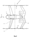
Fig. 6 shows another plan view of an aircraft according to the invention. -
Figure 1 shows aVTOL aircraft 1 having a fuselage orfuselage body 2 for transporting passengers and/or load. x, y, and z denote the aircraft axes (longitudinal, transverse, and vertical, respectively, as detailed above). Afront wing 3 is attached to thefuselage 2. Furthermore, arear wing 4 is attached to thefuselage 2 behind thefront wing 3 in a direction of forward flight (arrow FF) of theaircraft 1. A right connectingbeam 5a and a left connectingbeam 5b structurally connect thefront wing 3 and therear wing 4, which connectingbeams fuselage 2. Theaircraft 1 comprises six lifting units M1-M6, three of which are arranged on each one of the connectingbeams propeller 6b and at least onemotor 6a driving saidpropeller 6b, preferably an electric motor, and they are arranged with their respective propeller axis in an essentially vertical orientation (z axis). This is explicitly shown for only one (M6) of the lifting units M1-M6 inFigure 1 . - The lifting units M1-M6 are placed symmetrically about the longitudinal (x) and lateral (y) axes of the aircraft 1: Lifting units M1 and M5 are placed at equal distances (in x-direction) toward the front and the rear, respectively, when compared to lifting unit M3. The same holds for lifting units M2, M4, and M6. Furthermore, the three lifting units on each side of the
aircraft 1 are placed at equal transverse distances (in y-direction) from the aircraft's longitudinal axis. - Reference numerals P1-P6 denote rotor planes that can be defined as respective areas swept by the rotating
propellers 6b of lifting units M1-M6. Wing attachments to the connectingbeams front wing 3 and A4 forrear wing 4. - The
front wing 3 and therear wing 4, at least in portions thereof, i.e., the outer portion of therear wing 4 with respect to thefuselage 2, both define a sweep angle (γ, β) which is less than 90° (forward sweep).Rear wing 4 has a backward sweep (angle δ) in a region close to the fuselage 2 (V-Tail), which helps to reduce the length of thefuselage 2 while keeping a sufficient rear surface wing area Srear (cf. below). Preferred values for these angles are: 45° < γ < 135°, preferably γ = 75°, 30° < β < 90°, preferably β = 65°, and 70° < δ < 170°, preferably δ = 110°. - Reference numerals F1 and F2 denote forward propulsion units (pushers) that are attached at the right side and at the left side of the
fuselage 2, respectively, toward the rear of the aircraft 1 (in front of rear wing 4). The pushers can comprise at least one propeller and at least one motor driving said propeller (not shown). - The specific physical points of the
aircraft 1, which were defined earlier, are denoted as CoG (centre of gravity), CoA (centre of actuation), CA (aerodynamic centre) and NP (neutral point). Also denoted are the individual aerodynamic centres of both the front wing 3 (CAFront) and the rear wing 4 (CARear), respectively, for that part of each wing which extends betweenfuselage 2 and right connectingbeam 5a. The same applies to that part of each wing which extends betweenfuselage 2 and left connectingbeam 5b (not shown inFigure 1 ). As can be gathered fromFigure 1 , the centre of actuation CoA of theaircraft 1 is geometrically in the same longitudinal position (xCoA) as the aircraft's centre of gravity CoG (at least approximately), while the neutral point NP is located well aft of both the centre of actuation CoA and the centre of gravity CoG due to the forward sweep ofwings - The
front wing 3 has a wing area Sfront that is smaller than a wing area Srear of therear wing 4. In the present example 60% < Sfront/Srear < 70%. In sum, therear wing 4 comprises the surface of a V-Tail (wing half 4b) and a classical lifting wing surface (wing half 4a), which will become apparent fromFigs. 3 to 5 below. -
Figure 2 shows a side view of theaircraft 1 ofFigure 1 . Same elements are denoted by common reference numerals in all Figures. - The connecting beams (only
beam 5b is visible inFigure 2 ) are placed higher than (or above) thefuselage 2, i.e., in the z direction (cf.Figure 1 ). - M1+2 denotes lifting units M1 and M2, which are located behind one another in the line of sight. Same applies to lifting units M3 and M4 as well as lifting units M5 and M6, respectively.
- Reference numeral D denotes propeller downwash (only shown for one (M5+6) of the lifting units M1-M6). Said wing attachments (cf.
Figure 1 ) are located outside the downwash zones. -
Figure 3 shows a front view of theaircraft 1. As can be seen, in a plane perpendicular to a longitudinal axis (x) of theaircraft 1, therear wing 4 extends sideways from thefuselage 2 such thatrespective wing halves rear wing 4 form an angle α < 180°, preferably approximately 90° to 100°. Theinner wing half 4b forms the surface of a V-Tail, while theouter half 4a represents a classical lifting wing surface. -
Front wing 3 incorporates a dihedral angle (λ) which, combined with the above-mentioned sweep angle (γ < 90°), positively affects lateral/directional stability of theaircraft 1. Said angle λ may increase toward respective tips of thewing 3. Additionally, therear wing 4 incorporates an anhedral angle (ε) in order to create a high vertical offset VO in the region of higher downwash 7 (cf.Figure 2 ) of thefront wing 3 which occurs especially in the in-board portion of said wing 3 (spanwise). Said angle ε, too, may increase toward respective tips of thewing 4. In this way, thefront wing 3 and therear wing 4, when viewed along the longitudinal axis (x) of theaircraft 1, together form a closed loop shape. -
Figure 4 is a somewhat simplified version ofFigure 1 for to illustrate thefront wing 3 with its area Sfront being smaller than area Srear of therear wing 4. However, the rear wing surfaces produce less vertical lift due to the V-Tail configuration.Rear wing 4 comprises the surface of the V-Tail 4b and classical liftingwing surface 4a, which are illustrated by means of different shadings. - This is further illustrated in
Figure 5 , which is another front view of the aircraft 1 (cf.Figure 3 for additional details). - Finally, as illustrated in
Figure 6 , the V-Tail sweep angle δ, δ > 90°, also leads to an improved load transfer (dashed lines denoted by reference numeral 8) as the "V" configuration transfers loads from the connectingbeam 5b viawing 4a and via the V-tail 4b into thefuselage 2.
Claims (15)
- A VTOL aircraft (1), comprising:a fuselage (2) for transporting passengers and/or load;a front wing (3) attached to the fuselage (2);a rear wing (4) attached to the fuselage (2), behind the front wing (3) in a direction of forward flight (FF);a right connecting beam (5a) and a left connecting beam (5b), which connecting beams (5a, 5b) structurally connect the front wing (3) and the rear wing (4), which connecting beams (5a, 5b) are spaced apart from the fuselage (2); andat least two lifting units (M1-M6) on each one of the connecting beams (5a, 5b), which lifting units (M1-M6) each comprise at least one propeller (6b) and at least one motor (6a) driving said propeller (6b), preferably an electric motor, and are arranged with their respective propeller axis in an essentially vertical orientation (z);wherein the front wing (3), at least in portions thereof, has a sweep angle γ between γ = 45° and γ = 135°, preferably γ = 75°, and the rear wing (4), at least in portions thereof, has a forward sweep with sweep angle β ≥ 30°, preferably, β = 65°.
- The aircraft (1) of claim 1, wherein
the front wing (3) has a wing area (Sfront) that is smaller than a wing area (Srear) of the rear wing (4), preferably 60% < Sfront/Srear < 100%, more preferably 60% < Sfront/Srear < 70%. - The aircraft (1) of claim 1 or 2, wherein
the rear wing (4) is partly shaped in the form of a V-Tail with a sweep angle (δ) greater than 90°. - The aircraft (1) of any one of claims 1 through 3, wherein
in a plane perpendicular to a longitudinal axis (x) of the aircraft (1), the rear wing (4) extends sideways from the fuselage (2) such that respective wing halves (4a, 4b) form an angle (θ) < 180°, preferably approximately 90° to 100°. - The aircraft (1) of any one of claims 1 through 4, comprising
three lifting units (M1-M6) on each one of the connecting beams (5a, 5b). - The aircraft (1) of any one of claims 1 through 5, wherein
the lifting units (M1-M6) are placed symmetrically about a longitudinal (x-z) and a lateral (y-z) plane, respectively, of the aircraft (1). - The aircraft (1) of any one of claims 1 through 6, wherein
attachments (A3, A4) of the front wing (3) and the rear wing (4), respectively, to the connecting beams (5a, 5b) are placed in between respective rotor planes (P1-P6) swept by the propellers (6b). - The aircraft (1) of any one of claims 1 through 7, wherein
the rear wing (4) is placed higher in vertical position (z) than the front wing (3). - The aircraft (1) of any one of claims 1 through 8, wherein
the front wing (3) incorporates a dihedral angle (λ), preferably at respective tips thereof. - The aircraft (1) of any one of claims 1 through 9, wherein
the rear wing (4) incorporates an anhedral angle (ε), at least in an outer portion thereof, towards said connecting beams (5a, 5b). - The aircraft (1) of any one of claims 1 through 10, wherein
longitudinal aircraft stability, which is defined by a quantity Cm/a, is negative, Cm being a pitching moment coefficient and α being an angle of attack. - The aircraft (1) of any one of claims 1 through 11, wherein
a centre of actuation (CoA) is geometrically in the same longitudinal position (xCoA) as the aircraft's centre of gravity (CoG), while a neutral point (NP) is located aft of both the centre of actuation (CoA) and the centre of gravity (CoG). - The aircraft (1) of any one of claims 1 through 12, further comprising
at least one forward propulsion unit (F1, F2) preferably having at least one propeller and at least one motor driving said propeller, preferably an electric motor, more preferably located toward the rear of the aircraft (1). - The aircraft (1) of claim 13, wherein
at least one forward propulsion unit (F1, F2) is located on each side of the fuselage (2), preferably below both the front wing (3) and the rear wing (4) and most preferably forward of the rear wing (4). - The aircraft (1) of any one of claims 1 through 14, wherein
the front wing (3) and the rear wing (4), when viewed along a longitudinal axis (x) of the aircraft (1), together form a closed loop shape.
Priority Applications (3)
| Application Number | Priority Date | Filing Date | Title |
|---|---|---|---|
| EP21161173.6A EP4056471B1 (en) | 2021-03-08 | 2021-03-08 | Vtol aircraft |
| US17/591,811 US12049307B2 (en) | 2021-03-08 | 2022-02-03 | VTOL aircraft with electric propulsion |
| CN202210219767.8A CN115042968B (en) | 2021-03-08 | 2022-03-08 | Vertical take-off and landing aircraft |
Applications Claiming Priority (1)
| Application Number | Priority Date | Filing Date | Title |
|---|---|---|---|
| EP21161173.6A EP4056471B1 (en) | 2021-03-08 | 2021-03-08 | Vtol aircraft |
Publications (2)
| Publication Number | Publication Date |
|---|---|
| EP4056471A1 true EP4056471A1 (en) | 2022-09-14 |
| EP4056471B1 EP4056471B1 (en) | 2025-09-17 |
Family
ID=74859752
Family Applications (1)
| Application Number | Title | Priority Date | Filing Date |
|---|---|---|---|
| EP21161173.6A Active EP4056471B1 (en) | 2021-03-08 | 2021-03-08 | Vtol aircraft |
Country Status (3)
| Country | Link |
|---|---|
| US (1) | US12049307B2 (en) |
| EP (1) | EP4056471B1 (en) |
| CN (1) | CN115042968B (en) |
Cited By (1)
| Publication number | Priority date | Publication date | Assignee | Title |
|---|---|---|---|---|
| WO2025131428A1 (en) | 2023-12-19 | 2025-06-26 | Volocopter Technologies Gmbh | Aircraft |
Families Citing this family (11)
| Publication number | Priority date | Publication date | Assignee | Title |
|---|---|---|---|---|
| TR202022599A1 (en) * | 2020-12-31 | 2022-07-21 | Tusas Tuerk Havacilik Ve Uzay Sanayii Anonim Sirketi | a helicopter |
| US12559232B2 (en) * | 2021-05-31 | 2026-02-24 | Ampaire Inc. | Electric vertical takeoff and landing aircraft |
| US12195192B2 (en) * | 2022-04-30 | 2025-01-14 | Beta Air Llc | Hybrid propulsion systems for an electric aircraft |
| US11634232B1 (en) * | 2022-04-30 | 2023-04-25 | Beta Air, Llc | Hybrid propulsion systems for an electric aircraft |
| US11639230B1 (en) * | 2022-04-30 | 2023-05-02 | Beta Air, Llc | System for an integral hybrid electric aircraft |
| FI130682B1 (en) * | 2022-07-11 | 2024-01-16 | Raimo Hirvinen | A rocket stage, a rocket and a gliding part |
| US20240228036A9 (en) * | 2022-10-24 | 2024-07-11 | Textron Aviation Inc. | Electric Aircraft |
| JP2024176151A (en) | 2023-06-08 | 2024-12-19 | 国立研究開発法人宇宙航空研究開発機構 | Vertical take-off and landing aircraft |
| US12139253B1 (en) * | 2023-09-07 | 2024-11-12 | Textron Eaviation Inc. | Tiltrotor aircraft control system |
| CN117382877A (en) * | 2023-11-13 | 2024-01-12 | 中国直升机设计研究所 | A container-type eVTOL rotorcraft and an eVTOL rotorcraft cluster |
| USD1126102S1 (en) * | 2023-12-19 | 2026-05-12 | Volocopter Technologies Gmbh | Aircraft |
Citations (9)
| Publication number | Priority date | Publication date | Assignee | Title |
|---|---|---|---|---|
| US3834654A (en) | 1973-03-19 | 1974-09-10 | Lockheed Aircraft Corp | Boxplane wing and aircraft |
| US20060151666A1 (en) * | 2005-01-13 | 2006-07-13 | Vandermey Timothy | Vertical take-off and landing (VTOL) aircraft with distributed thrust and control |
| US9499266B1 (en) | 2014-06-24 | 2016-11-22 | Elytron Aircraft LLC | Five-wing aircraft to permit smooth transitions between vertical and horizontal flight |
| US20180105268A1 (en) | 2016-10-18 | 2018-04-19 | Kitty Hawk Corporation | Ventilated rotor mounting boom for personal aircraft |
| US10081436B1 (en) | 2017-07-06 | 2018-09-25 | Autoflightx International Limited | Hybrid VTOL fixed-wing drone |
| US20180305005A1 (en) * | 2017-04-24 | 2018-10-25 | AFS-DV VTOL Technologies Corporation | Vertical Take-Off and Landing Aircraft |
| US20200290725A1 (en) * | 2018-09-21 | 2020-09-17 | Bell Textron Inc. | Ducted thrusters |
| EP3757004A1 (en) | 2019-06-27 | 2020-12-30 | Volocopter GmbH | Vtol aircraft with wing connecting booms |
| US20210031909A1 (en) * | 2019-07-30 | 2021-02-04 | Rolls-Royce Plc | Lift rotor system |
Family Cites Families (13)
| Publication number | Priority date | Publication date | Assignee | Title |
|---|---|---|---|---|
| USD311720S (en) | 1988-11-14 | 1990-10-30 | Butler Gerald L | Aircraft |
| DE19947633A1 (en) * | 1998-10-02 | 2000-09-28 | Andreas Lebelt | W-shaped main lift wing for aircraft, with different setting angles of surface sections |
| US9545993B2 (en) * | 2007-01-12 | 2017-01-17 | John William McGinnis | Aircraft stability and efficient control through induced drag reduction |
| RU2608122C1 (en) * | 2016-02-17 | 2017-01-13 | Дмитрий Сергеевич Дуров | Heavy high-speed rotary-wing aircraft |
| US20180273170A1 (en) * | 2017-03-21 | 2018-09-27 | Regents Of The University Of Minnesota | Transformable unmanned aerial vehicle |
| RU180474U1 (en) * | 2017-10-26 | 2018-06-14 | Федеральное государственное унитарное предприятие "Сибирский научно-исследовательский институт авиации им. С.А. Чаплыгина" | Vertical takeoff and landing airplane |
| CN112533824B (en) * | 2018-08-19 | 2024-08-16 | 安德拉斯·海尔纳迪 | Method for improving the concept of a closed-wing aircraft and corresponding aircraft construction |
| EP3702276B1 (en) * | 2019-02-27 | 2021-01-13 | AIRBUS HELICOPTERS DEUTSCHLAND GmbH | A multirotor joined-wing aircraft with vtol capabilities |
| GB2583332A (en) * | 2019-04-09 | 2020-10-28 | Airbus Operations Ltd | Aircraft wing |
| CN110182361B (en) * | 2019-05-28 | 2022-09-27 | 湖北电鹰科技有限公司 | Vertically taking off and landing fixed wing unmanned aerial vehicle capable of tilting |
| KR102927314B1 (en) * | 2019-05-29 | 2026-02-13 | 크래프트 에어로스페이스 테크놀로지스 인크. | A new aircraft design using tandem wings and a distributed propulsion system. |
| GB2585864B (en) * | 2019-07-18 | 2022-04-27 | Gkn Aerospace Services Ltd | An aircraft |
| CN111086632A (en) * | 2020-02-10 | 2020-05-01 | 廊坊希达电子科技有限公司 | Electric vertical take-off and landing unmanned aerial vehicle |
-
2021
- 2021-03-08 EP EP21161173.6A patent/EP4056471B1/en active Active
-
2022
- 2022-02-03 US US17/591,811 patent/US12049307B2/en active Active
- 2022-03-08 CN CN202210219767.8A patent/CN115042968B/en active Active
Patent Citations (10)
| Publication number | Priority date | Publication date | Assignee | Title |
|---|---|---|---|---|
| US3834654A (en) | 1973-03-19 | 1974-09-10 | Lockheed Aircraft Corp | Boxplane wing and aircraft |
| US20060151666A1 (en) * | 2005-01-13 | 2006-07-13 | Vandermey Timothy | Vertical take-off and landing (VTOL) aircraft with distributed thrust and control |
| US9499266B1 (en) | 2014-06-24 | 2016-11-22 | Elytron Aircraft LLC | Five-wing aircraft to permit smooth transitions between vertical and horizontal flight |
| US20180105268A1 (en) | 2016-10-18 | 2018-04-19 | Kitty Hawk Corporation | Ventilated rotor mounting boom for personal aircraft |
| US20180305005A1 (en) * | 2017-04-24 | 2018-10-25 | AFS-DV VTOL Technologies Corporation | Vertical Take-Off and Landing Aircraft |
| US10081436B1 (en) | 2017-07-06 | 2018-09-25 | Autoflightx International Limited | Hybrid VTOL fixed-wing drone |
| US20200290725A1 (en) * | 2018-09-21 | 2020-09-17 | Bell Textron Inc. | Ducted thrusters |
| EP3757004A1 (en) | 2019-06-27 | 2020-12-30 | Volocopter GmbH | Vtol aircraft with wing connecting booms |
| US20200407055A1 (en) * | 2019-06-27 | 2020-12-31 | Volocopter Gmbh | Aircraft |
| US20210031909A1 (en) * | 2019-07-30 | 2021-02-04 | Rolls-Royce Plc | Lift rotor system |
Cited By (2)
| Publication number | Priority date | Publication date | Assignee | Title |
|---|---|---|---|---|
| WO2025131428A1 (en) | 2023-12-19 | 2025-06-26 | Volocopter Technologies Gmbh | Aircraft |
| DE102023135708A1 (en) * | 2023-12-19 | 2025-06-26 | Volocopter Gmbh | aircraft |
Also Published As
| Publication number | Publication date |
|---|---|
| US20220281593A1 (en) | 2022-09-08 |
| EP4056471B1 (en) | 2025-09-17 |
| CN115042968A (en) | 2022-09-13 |
| US12049307B2 (en) | 2024-07-30 |
| CN115042968B (en) | 2025-07-04 |
Similar Documents
| Publication | Publication Date | Title |
|---|---|---|
| US12049307B2 (en) | VTOL aircraft with electric propulsion | |
| CN111619785B (en) | Multi-rotor aircraft suitable for vertical take-off and landing | |
| KR102594866B1 (en) | electric tiltrotor aircraft | |
| CN112141328B (en) | airplane | |
| Yeo | Design and aeromechanics investigation of compound helicopters | |
| EP3296202B1 (en) | Wing extension winglets for tiltrotor aircraft | |
| US8393564B2 (en) | Personal aircraft | |
| US5086993A (en) | Airplane with variable-incidence wing | |
| US6592073B1 (en) | Amphibious aircraft | |
| KR102758509B1 (en) | Tail sitter | |
| KR102680619B1 (en) | tail sitter | |
| EP3087003B1 (en) | An unmanned aerial vehicle | |
| US20090159740A1 (en) | Coaxial rotor aircraft | |
| US5108044A (en) | Shroud-fin integration shelf for a helicopter empennage structure | |
| CN108082466A (en) | A kind of tilting duct connection wing layout vertically taking off and landing flyer | |
| CN103448910A (en) | Aircraft capable of vertically taking off and landing at high speed | |
| CN106218887A (en) | A kind of vertically taking off and landing flyer of distributed-power device layout | |
| US20060016931A1 (en) | High-lift, low-drag dual fuselage aircraft | |
| US20020047069A1 (en) | Directional control and aerofoil system for aircraft | |
| US12017754B2 (en) | Download reducing wingtips | |
| RU2655249C1 (en) | High-speed helicopter-amphibious aircraft | |
| Kentfield | Case for aircraft with outboard horizontal stabilizers | |
| US10654556B2 (en) | VTOL aircraft with wings | |
| RU2838699C1 (en) | Unmanned aerial vehicle | |
| RU2775087C2 (en) | Tailsitter |
Legal Events
| Date | Code | Title | Description |
|---|---|---|---|
| PUAI | Public reference made under article 153(3) epc to a published international application that has entered the european phase |
Free format text: ORIGINAL CODE: 0009012 |
|
| STAA | Information on the status of an ep patent application or granted ep patent |
Free format text: STATUS: THE APPLICATION HAS BEEN PUBLISHED |
|
| AK | Designated contracting states |
Kind code of ref document: A1 Designated state(s): AL AT BE BG CH CY CZ DE DK EE ES FI FR GB GR HR HU IE IS IT LI LT LU LV MC MK MT NL NO PL PT RO RS SE SI SK SM TR |
|
| STAA | Information on the status of an ep patent application or granted ep patent |
Free format text: STATUS: REQUEST FOR EXAMINATION WAS MADE |
|
| 17P | Request for examination filed |
Effective date: 20221007 |
|
| RBV | Designated contracting states (corrected) |
Designated state(s): AL AT BE BG CH CY CZ DE DK EE ES FI FR GB GR HR HU IE IS IT LI LT LU LV MC MK MT NL NO PL PT RO RS SE SI SK SM TR |
|
| STAA | Information on the status of an ep patent application or granted ep patent |
Free format text: STATUS: EXAMINATION IS IN PROGRESS |
|
| 17Q | First examination report despatched |
Effective date: 20230728 |
|
| RAP3 | Party data changed (applicant data changed or rights of an application transferred) |
Owner name: VOLOCOPTER GMBH |
|
| GRAP | Despatch of communication of intention to grant a patent |
Free format text: ORIGINAL CODE: EPIDOSNIGR1 |
|
| STAA | Information on the status of an ep patent application or granted ep patent |
Free format text: STATUS: GRANT OF PATENT IS INTENDED |
|
| INTG | Intention to grant announced |
Effective date: 20241022 |
|
| GRAS | Grant fee paid |
Free format text: ORIGINAL CODE: EPIDOSNIGR3 |
|
| GRAA | (expected) grant |
Free format text: ORIGINAL CODE: 0009210 |
|
| STAA | Information on the status of an ep patent application or granted ep patent |
Free format text: STATUS: THE PATENT HAS BEEN GRANTED |
|
| AK | Designated contracting states |
Kind code of ref document: B1 Designated state(s): AL AT BE BG CH CY CZ DE DK EE ES FI FR GB GR HR HU IE IS IT LI LT LU LV MC MK MT NL NO PL PT RO RS SE SI SK SM TR |
|
| REG | Reference to a national code |
Ref country code: CH Ref legal event code: EP Ref country code: GB Ref legal event code: FG4D |
|
| REG | Reference to a national code |
Ref country code: DE Ref legal event code: R096 Ref document number: 602021029858 Country of ref document: DE |
|
| PUAC | Information related to the publication of a b1 document modified or deleted |
Free format text: ORIGINAL CODE: 0009299EPPU |
|
| STAA | Information on the status of an ep patent application or granted ep patent |
Free format text: STATUS: GRANT OF PATENT IS INTENDED |
|
| REG | Reference to a national code |
Ref country code: IE Ref legal event code: FG4D |
|
| REG | Reference to a national code |
Ref country code: CH Ref legal event code: PK Free format text: DIE ERTEILUNG WURDE VOM EPA WIDERRUFEN. |
|
| P01 | Opt-out of the competence of the unified patent court (upc) registered |
Free format text: CASE NUMBER: APP_19568/2025 Effective date: 20250423 |
|
| 29U | Proceedings interrupted after grant according to rule 142 epc |
Effective date: 20250301 |
|
| 29W | Proceedings resumed after grant [after interruption of proceedings according to rule 142 epc] |
Effective date: 20250801 |
|
| DB1 | Publication of patent cancelled |
Effective date: 20250516 |
|
| REG | Reference to a national code |
Ref country code: DE Ref legal event code: R107 Ref country code: DE Ref legal event code: R107 Ref document number: 602021029858 Country of ref document: DE |
|
| REG | Reference to a national code |
Ref country code: AT Ref legal event code: REZ Ref document number: 1789849 Country of ref document: AT Kind code of ref document: T Effective date: 20250430 |
|
| GRAA | (expected) grant |
Free format text: ORIGINAL CODE: 0009210 |
|
| STAA | Information on the status of an ep patent application or granted ep patent |
Free format text: STATUS: THE PATENT HAS BEEN GRANTED |
|
| REG | Reference to a national code |
Ref country code: DE Ref legal event code: R081 Ref document number: 602021029858 Country of ref document: DE Owner name: VOLOCOPTER TECHNOLOGIES GMBH, DE Free format text: FORMER OWNER: ANMELDERANGABEN UNKLAR / UNVOLLSTAENDIG, 80297 MUENCHEN, DE |
|
| RAP3 | Party data changed (applicant data changed or rights of an application transferred) |
Owner name: VOLOCOPTER TECHNOLOGIES GMBH |
|
| AK | Designated contracting states |
Kind code of ref document: B1 Designated state(s): AL AT BE BG CH CY CZ DE DK EE ES FI FR GB GR HR HU IE IS IT LI LT LU LV MC MK MT NL NO PL PT RO RS SE SI SK SM TR |
|
| REG | Reference to a national code |
Ref country code: CH Ref legal event code: EP |
|
| REG | Reference to a national code |
Ref country code: DE Ref legal event code: R096 Ref document number: 602021029858 Country of ref document: DE |
|
| PG25 | Lapsed in a contracting state [announced via postgrant information from national office to epo] |
Ref country code: PL Free format text: LAPSE BECAUSE OF FAILURE TO SUBMIT A TRANSLATION OF THE DESCRIPTION OR TO PAY THE FEE WITHIN THE PRESCRIBED TIME-LIMIT Effective date: 20250917 |
|
| PG25 | Lapsed in a contracting state [announced via postgrant information from national office to epo] |
Ref country code: NO Free format text: LAPSE BECAUSE OF FAILURE TO SUBMIT A TRANSLATION OF THE DESCRIPTION OR TO PAY THE FEE WITHIN THE PRESCRIBED TIME-LIMIT Effective date: 20251217 |
|
| REG | Reference to a national code |
Ref country code: LT Ref legal event code: MG9D |
|
| PG25 | Lapsed in a contracting state [announced via postgrant information from national office to epo] |
Ref country code: FI Free format text: LAPSE BECAUSE OF FAILURE TO SUBMIT A TRANSLATION OF THE DESCRIPTION OR TO PAY THE FEE WITHIN THE PRESCRIBED TIME-LIMIT Effective date: 20250917 |
|
| PG25 | Lapsed in a contracting state [announced via postgrant information from national office to epo] |
Ref country code: HR Free format text: LAPSE BECAUSE OF FAILURE TO SUBMIT A TRANSLATION OF THE DESCRIPTION OR TO PAY THE FEE WITHIN THE PRESCRIBED TIME-LIMIT Effective date: 20250917 |
|
| REG | Reference to a national code |
Ref country code: NL Ref legal event code: MP Effective date: 20250917 |
|
| PG25 | Lapsed in a contracting state [announced via postgrant information from national office to epo] |
Ref country code: LV Free format text: LAPSE BECAUSE OF FAILURE TO SUBMIT A TRANSLATION OF THE DESCRIPTION OR TO PAY THE FEE WITHIN THE PRESCRIBED TIME-LIMIT Effective date: 20250917 |
|
| PG25 | Lapsed in a contracting state [announced via postgrant information from national office to epo] |
Ref country code: BG Free format text: LAPSE BECAUSE OF FAILURE TO SUBMIT A TRANSLATION OF THE DESCRIPTION OR TO PAY THE FEE WITHIN THE PRESCRIBED TIME-LIMIT Effective date: 20250917 |
|
| PG25 | Lapsed in a contracting state [announced via postgrant information from national office to epo] |
Ref country code: NL Free format text: LAPSE BECAUSE OF FAILURE TO SUBMIT A TRANSLATION OF THE DESCRIPTION OR TO PAY THE FEE WITHIN THE PRESCRIBED TIME-LIMIT Effective date: 20250917 |
|
| REG | Reference to a national code |
Ref country code: AT Ref legal event code: MK05 Ref document number: 1789849 Country of ref document: AT Kind code of ref document: T Effective date: 20250917 |
|
| PG25 | Lapsed in a contracting state [announced via postgrant information from national office to epo] |
Ref country code: SM Free format text: LAPSE BECAUSE OF FAILURE TO SUBMIT A TRANSLATION OF THE DESCRIPTION OR TO PAY THE FEE WITHIN THE PRESCRIBED TIME-LIMIT Effective date: 20250917 |
|
| PGFP | Annual fee paid to national office [announced via postgrant information from national office to epo] |
Ref country code: GB Payment date: 20260324 Year of fee payment: 6 |
|
| PG25 | Lapsed in a contracting state [announced via postgrant information from national office to epo] |
Ref country code: ES Free format text: LAPSE BECAUSE OF FAILURE TO SUBMIT A TRANSLATION OF THE DESCRIPTION OR TO PAY THE FEE WITHIN THE PRESCRIBED TIME-LIMIT Effective date: 20250917 |
|
| PG25 | Lapsed in a contracting state [announced via postgrant information from national office to epo] |
Ref country code: DK Free format text: LAPSE BECAUSE OF FAILURE TO SUBMIT A TRANSLATION OF THE DESCRIPTION OR TO PAY THE FEE WITHIN THE PRESCRIBED TIME-LIMIT Effective date: 20250917 |
|
| PGFP | Annual fee paid to national office [announced via postgrant information from national office to epo] |
Ref country code: DE Payment date: 20260320 Year of fee payment: 6 |
|
| PG25 | Lapsed in a contracting state [announced via postgrant information from national office to epo] |
Ref country code: AT Free format text: LAPSE BECAUSE OF FAILURE TO SUBMIT A TRANSLATION OF THE DESCRIPTION OR TO PAY THE FEE WITHIN THE PRESCRIBED TIME-LIMIT Effective date: 20250917 |
|
| PG25 | Lapsed in a contracting state [announced via postgrant information from national office to epo] |
Ref country code: IT Free format text: LAPSE BECAUSE OF FAILURE TO SUBMIT A TRANSLATION OF THE DESCRIPTION OR TO PAY THE FEE WITHIN THE PRESCRIBED TIME-LIMIT Effective date: 20250917 |
|
| PGFP | Annual fee paid to national office [announced via postgrant information from national office to epo] |
Ref country code: FR Payment date: 20260325 Year of fee payment: 6 |
|
| PG25 | Lapsed in a contracting state [announced via postgrant information from national office to epo] |
Ref country code: CZ Free format text: LAPSE BECAUSE OF FAILURE TO SUBMIT A TRANSLATION OF THE DESCRIPTION OR TO PAY THE FEE WITHIN THE PRESCRIBED TIME-LIMIT Effective date: 20250917 Ref country code: PT Free format text: LAPSE BECAUSE OF FAILURE TO SUBMIT A TRANSLATION OF THE DESCRIPTION OR TO PAY THE FEE WITHIN THE PRESCRIBED TIME-LIMIT Effective date: 20260119 |
|
| PG25 | Lapsed in a contracting state [announced via postgrant information from national office to epo] |
Ref country code: SK Free format text: LAPSE BECAUSE OF FAILURE TO SUBMIT A TRANSLATION OF THE DESCRIPTION OR TO PAY THE FEE WITHIN THE PRESCRIBED TIME-LIMIT Effective date: 20250917 |