EP4056414A1 - A method for determining a derating factor of an energy storage system, a control unit, a power system and a vehicle - Google Patents
A method for determining a derating factor of an energy storage system, a control unit, a power system and a vehicle Download PDFInfo
- Publication number
- EP4056414A1 EP4056414A1 EP21161700.6A EP21161700A EP4056414A1 EP 4056414 A1 EP4056414 A1 EP 4056414A1 EP 21161700 A EP21161700 A EP 21161700A EP 4056414 A1 EP4056414 A1 EP 4056414A1
- Authority
- EP
- European Patent Office
- Prior art keywords
- load
- energy storage
- value
- storage system
- electrical
- Prior art date
- Legal status (The legal status is an assumption and is not a legal conclusion. Google has not performed a legal analysis and makes no representation as to the accuracy of the status listed.)
- Pending
Links
Images

Classifications
-
- B—PERFORMING OPERATIONS; TRANSPORTING
- B60—VEHICLES IN GENERAL
- B60L—PROPULSION OF ELECTRICALLY-PROPELLED VEHICLES; SUPPLYING ELECTRIC POWER FOR AUXILIARY EQUIPMENT OF ELECTRICALLY-PROPELLED VEHICLES; ELECTRODYNAMIC BRAKE SYSTEMS FOR VEHICLES IN GENERAL; MAGNETIC SUSPENSION OR LEVITATION FOR VEHICLES; MONITORING OPERATING VARIABLES OF ELECTRICALLY-PROPELLED VEHICLES; ELECTRIC SAFETY DEVICES FOR ELECTRICALLY-PROPELLED VEHICLES
- B60L58/00—Methods or circuit arrangements for monitoring or controlling batteries or fuel cells, specially adapted for electric vehicles
- B60L58/10—Methods or circuit arrangements for monitoring or controlling batteries or fuel cells, specially adapted for electric vehicles for monitoring or controlling batteries
- B60L58/16—Methods or circuit arrangements for monitoring or controlling batteries or fuel cells, specially adapted for electric vehicles for monitoring or controlling batteries responding to battery ageing, e.g. to the number of charging cycles or the state of health [SoH]
-
- H—ELECTRICITY
- H02—GENERATION; CONVERSION OR DISTRIBUTION OF ELECTRIC POWER
- H02J—ELECTRIC POWER NETWORKS; CIRCUIT ARRANGEMENTS OR SYSTEMS FOR SUPPLYING OR DISTRIBUTING ELECTRIC POWER; SYSTEMS FOR STORING ELECTRIC ENERGY
- H02J7/00—Circuit arrangements for charging or discharging batteries or for supplying loads from batteries
- H02J7/90—Regulation of charging or discharging current or voltage
- H02J7/933—Regulation of charging or discharging current or voltage the cycle being controlled or terminated in response to electric parameters
-
- B—PERFORMING OPERATIONS; TRANSPORTING
- B60—VEHICLES IN GENERAL
- B60L—PROPULSION OF ELECTRICALLY-PROPELLED VEHICLES; SUPPLYING ELECTRIC POWER FOR AUXILIARY EQUIPMENT OF ELECTRICALLY-PROPELLED VEHICLES; ELECTRODYNAMIC BRAKE SYSTEMS FOR VEHICLES IN GENERAL; MAGNETIC SUSPENSION OR LEVITATION FOR VEHICLES; MONITORING OPERATING VARIABLES OF ELECTRICALLY-PROPELLED VEHICLES; ELECTRIC SAFETY DEVICES FOR ELECTRICALLY-PROPELLED VEHICLES
- B60L3/00—Electric devices on electrically-propelled vehicles for safety purposes; Monitoring operating variables, e.g. speed, deceleration or energy consumption
- B60L3/0023—Detecting, eliminating, remedying or compensating for drive train abnormalities, e.g. failures within the drive train
- B60L3/0046—Detecting, eliminating, remedying or compensating for drive train abnormalities, e.g. failures within the drive train relating to electric energy storage systems, e.g. batteries or capacitors
-
- B—PERFORMING OPERATIONS; TRANSPORTING
- B60—VEHICLES IN GENERAL
- B60L—PROPULSION OF ELECTRICALLY-PROPELLED VEHICLES; SUPPLYING ELECTRIC POWER FOR AUXILIARY EQUIPMENT OF ELECTRICALLY-PROPELLED VEHICLES; ELECTRODYNAMIC BRAKE SYSTEMS FOR VEHICLES IN GENERAL; MAGNETIC SUSPENSION OR LEVITATION FOR VEHICLES; MONITORING OPERATING VARIABLES OF ELECTRICALLY-PROPELLED VEHICLES; ELECTRIC SAFETY DEVICES FOR ELECTRICALLY-PROPELLED VEHICLES
- B60L3/00—Electric devices on electrically-propelled vehicles for safety purposes; Monitoring operating variables, e.g. speed, deceleration or energy consumption
- B60L3/0092—Electric devices on electrically-propelled vehicles for safety purposes; Monitoring operating variables, e.g. speed, deceleration or energy consumption with use of redundant elements for safety purposes
-
- B—PERFORMING OPERATIONS; TRANSPORTING
- B60—VEHICLES IN GENERAL
- B60L—PROPULSION OF ELECTRICALLY-PROPELLED VEHICLES; SUPPLYING ELECTRIC POWER FOR AUXILIARY EQUIPMENT OF ELECTRICALLY-PROPELLED VEHICLES; ELECTRODYNAMIC BRAKE SYSTEMS FOR VEHICLES IN GENERAL; MAGNETIC SUSPENSION OR LEVITATION FOR VEHICLES; MONITORING OPERATING VARIABLES OF ELECTRICALLY-PROPELLED VEHICLES; ELECTRIC SAFETY DEVICES FOR ELECTRICALLY-PROPELLED VEHICLES
- B60L53/00—Methods of charging batteries, specially adapted for electric vehicles; Charging stations or on-board charging equipment therefor; Exchange of energy storage elements in electric vehicles
- B60L53/60—Monitoring or controlling charging stations
- B60L53/62—Monitoring or controlling charging stations in response to charging parameters, e.g. current, voltage or electrical charge
-
- B—PERFORMING OPERATIONS; TRANSPORTING
- B60—VEHICLES IN GENERAL
- B60L—PROPULSION OF ELECTRICALLY-PROPELLED VEHICLES; SUPPLYING ELECTRIC POWER FOR AUXILIARY EQUIPMENT OF ELECTRICALLY-PROPELLED VEHICLES; ELECTRODYNAMIC BRAKE SYSTEMS FOR VEHICLES IN GENERAL; MAGNETIC SUSPENSION OR LEVITATION FOR VEHICLES; MONITORING OPERATING VARIABLES OF ELECTRICALLY-PROPELLED VEHICLES; ELECTRIC SAFETY DEVICES FOR ELECTRICALLY-PROPELLED VEHICLES
- B60L58/00—Methods or circuit arrangements for monitoring or controlling batteries or fuel cells, specially adapted for electric vehicles
- B60L58/10—Methods or circuit arrangements for monitoring or controlling batteries or fuel cells, specially adapted for electric vehicles for monitoring or controlling batteries
-
- B—PERFORMING OPERATIONS; TRANSPORTING
- B60—VEHICLES IN GENERAL
- B60L—PROPULSION OF ELECTRICALLY-PROPELLED VEHICLES; SUPPLYING ELECTRIC POWER FOR AUXILIARY EQUIPMENT OF ELECTRICALLY-PROPELLED VEHICLES; ELECTRODYNAMIC BRAKE SYSTEMS FOR VEHICLES IN GENERAL; MAGNETIC SUSPENSION OR LEVITATION FOR VEHICLES; MONITORING OPERATING VARIABLES OF ELECTRICALLY-PROPELLED VEHICLES; ELECTRIC SAFETY DEVICES FOR ELECTRICALLY-PROPELLED VEHICLES
- B60L58/00—Methods or circuit arrangements for monitoring or controlling batteries or fuel cells, specially adapted for electric vehicles
- B60L58/10—Methods or circuit arrangements for monitoring or controlling batteries or fuel cells, specially adapted for electric vehicles for monitoring or controlling batteries
- B60L58/12—Methods or circuit arrangements for monitoring or controlling batteries or fuel cells, specially adapted for electric vehicles for monitoring or controlling batteries responding to state of charge [SoC]
-
- B—PERFORMING OPERATIONS; TRANSPORTING
- B60—VEHICLES IN GENERAL
- B60L—PROPULSION OF ELECTRICALLY-PROPELLED VEHICLES; SUPPLYING ELECTRIC POWER FOR AUXILIARY EQUIPMENT OF ELECTRICALLY-PROPELLED VEHICLES; ELECTRODYNAMIC BRAKE SYSTEMS FOR VEHICLES IN GENERAL; MAGNETIC SUSPENSION OR LEVITATION FOR VEHICLES; MONITORING OPERATING VARIABLES OF ELECTRICALLY-PROPELLED VEHICLES; ELECTRIC SAFETY DEVICES FOR ELECTRICALLY-PROPELLED VEHICLES
- B60L58/00—Methods or circuit arrangements for monitoring or controlling batteries or fuel cells, specially adapted for electric vehicles
- B60L58/10—Methods or circuit arrangements for monitoring or controlling batteries or fuel cells, specially adapted for electric vehicles for monitoring or controlling batteries
- B60L58/12—Methods or circuit arrangements for monitoring or controlling batteries or fuel cells, specially adapted for electric vehicles for monitoring or controlling batteries responding to state of charge [SoC]
- B60L58/14—Preventing excessive discharging
-
- B—PERFORMING OPERATIONS; TRANSPORTING
- B60—VEHICLES IN GENERAL
- B60L—PROPULSION OF ELECTRICALLY-PROPELLED VEHICLES; SUPPLYING ELECTRIC POWER FOR AUXILIARY EQUIPMENT OF ELECTRICALLY-PROPELLED VEHICLES; ELECTRODYNAMIC BRAKE SYSTEMS FOR VEHICLES IN GENERAL; MAGNETIC SUSPENSION OR LEVITATION FOR VEHICLES; MONITORING OPERATING VARIABLES OF ELECTRICALLY-PROPELLED VEHICLES; ELECTRIC SAFETY DEVICES FOR ELECTRICALLY-PROPELLED VEHICLES
- B60L58/00—Methods or circuit arrangements for monitoring or controlling batteries or fuel cells, specially adapted for electric vehicles
- B60L58/10—Methods or circuit arrangements for monitoring or controlling batteries or fuel cells, specially adapted for electric vehicles for monitoring or controlling batteries
- B60L58/24—Methods or circuit arrangements for monitoring or controlling batteries or fuel cells, specially adapted for electric vehicles for monitoring or controlling batteries for controlling the temperature of batteries
-
- B—PERFORMING OPERATIONS; TRANSPORTING
- B60—VEHICLES IN GENERAL
- B60L—PROPULSION OF ELECTRICALLY-PROPELLED VEHICLES; SUPPLYING ELECTRIC POWER FOR AUXILIARY EQUIPMENT OF ELECTRICALLY-PROPELLED VEHICLES; ELECTRODYNAMIC BRAKE SYSTEMS FOR VEHICLES IN GENERAL; MAGNETIC SUSPENSION OR LEVITATION FOR VEHICLES; MONITORING OPERATING VARIABLES OF ELECTRICALLY-PROPELLED VEHICLES; ELECTRIC SAFETY DEVICES FOR ELECTRICALLY-PROPELLED VEHICLES
- B60L58/00—Methods or circuit arrangements for monitoring or controlling batteries or fuel cells, specially adapted for electric vehicles
- B60L58/10—Methods or circuit arrangements for monitoring or controlling batteries or fuel cells, specially adapted for electric vehicles for monitoring or controlling batteries
- B60L58/24—Methods or circuit arrangements for monitoring or controlling batteries or fuel cells, specially adapted for electric vehicles for monitoring or controlling batteries for controlling the temperature of batteries
- B60L58/25—Methods or circuit arrangements for monitoring or controlling batteries or fuel cells, specially adapted for electric vehicles for monitoring or controlling batteries for controlling the temperature of batteries by controlling the electric load
-
- H—ELECTRICITY
- H02—GENERATION; CONVERSION OR DISTRIBUTION OF ELECTRIC POWER
- H02J—ELECTRIC POWER NETWORKS; CIRCUIT ARRANGEMENTS OR SYSTEMS FOR SUPPLYING OR DISTRIBUTING ELECTRIC POWER; SYSTEMS FOR STORING ELECTRIC ENERGY
- H02J7/00—Circuit arrangements for charging or discharging batteries or for supplying loads from batteries
- H02J7/80—Circuit arrangements for charging or discharging batteries or for supplying loads from batteries including monitoring or indicating arrangements
-
- H—ELECTRICITY
- H02—GENERATION; CONVERSION OR DISTRIBUTION OF ELECTRIC POWER
- H02J—ELECTRIC POWER NETWORKS; CIRCUIT ARRANGEMENTS OR SYSTEMS FOR SUPPLYING OR DISTRIBUTING ELECTRIC POWER; SYSTEMS FOR STORING ELECTRIC ENERGY
- H02J7/00—Circuit arrangements for charging or discharging batteries or for supplying loads from batteries
- H02J7/855—Circuit arrangements for charging or discharging batteries or for supplying loads from batteries with circuits adapted for supplying loads from the battery
-
- B—PERFORMING OPERATIONS; TRANSPORTING
- B60—VEHICLES IN GENERAL
- B60L—PROPULSION OF ELECTRICALLY-PROPELLED VEHICLES; SUPPLYING ELECTRIC POWER FOR AUXILIARY EQUIPMENT OF ELECTRICALLY-PROPELLED VEHICLES; ELECTRODYNAMIC BRAKE SYSTEMS FOR VEHICLES IN GENERAL; MAGNETIC SUSPENSION OR LEVITATION FOR VEHICLES; MONITORING OPERATING VARIABLES OF ELECTRICALLY-PROPELLED VEHICLES; ELECTRIC SAFETY DEVICES FOR ELECTRICALLY-PROPELLED VEHICLES
- B60L2200/00—Type of vehicles
- B60L2200/32—Waterborne vessels
-
- B—PERFORMING OPERATIONS; TRANSPORTING
- B60—VEHICLES IN GENERAL
- B60L—PROPULSION OF ELECTRICALLY-PROPELLED VEHICLES; SUPPLYING ELECTRIC POWER FOR AUXILIARY EQUIPMENT OF ELECTRICALLY-PROPELLED VEHICLES; ELECTRODYNAMIC BRAKE SYSTEMS FOR VEHICLES IN GENERAL; MAGNETIC SUSPENSION OR LEVITATION FOR VEHICLES; MONITORING OPERATING VARIABLES OF ELECTRICALLY-PROPELLED VEHICLES; ELECTRIC SAFETY DEVICES FOR ELECTRICALLY-PROPELLED VEHICLES
- B60L2240/00—Control parameters of input or output; Target parameters
- B60L2240/40—Drive Train control parameters
- B60L2240/54—Drive Train control parameters related to batteries
-
- B—PERFORMING OPERATIONS; TRANSPORTING
- B60—VEHICLES IN GENERAL
- B60L—PROPULSION OF ELECTRICALLY-PROPELLED VEHICLES; SUPPLYING ELECTRIC POWER FOR AUXILIARY EQUIPMENT OF ELECTRICALLY-PROPELLED VEHICLES; ELECTRODYNAMIC BRAKE SYSTEMS FOR VEHICLES IN GENERAL; MAGNETIC SUSPENSION OR LEVITATION FOR VEHICLES; MONITORING OPERATING VARIABLES OF ELECTRICALLY-PROPELLED VEHICLES; ELECTRIC SAFETY DEVICES FOR ELECTRICALLY-PROPELLED VEHICLES
- B60L2240/00—Control parameters of input or output; Target parameters
- B60L2240/40—Drive Train control parameters
- B60L2240/54—Drive Train control parameters related to batteries
- B60L2240/549—Current
-
- B—PERFORMING OPERATIONS; TRANSPORTING
- B60—VEHICLES IN GENERAL
- B60Y—INDEXING SCHEME RELATING TO ASPECTS CROSS-CUTTING VEHICLE TECHNOLOGY
- B60Y2200/00—Type of vehicle
- B60Y2200/90—Vehicles comprising electric prime movers
- B60Y2200/91—Electric vehicles
Definitions
- the present disclosure relates to a method for determining a derating factor for a rechargeable energy storage system and to a method for operating a rechargeable energy storage system.
- the present disclosure also relates to a control unit configured to monitor and control an electrical load, a computer program, a computer readable medium, a power system comprising the control unit and an electrically powered vehicle or vessel comprising the control unit and/or the power system.
- Rechargeable Energy Storage Systems require special consideration for controlling power outtake, especially during transient conditions, to avoid impacting the State of Health (SoH) of the storage system, e.g. batteries. This is particularly true for applications using a rechargeable energy storage system for traction of vehicles or marine vessels, but it may also be required for other applications where a rechargeable energy storage system frequently supplies electrical loads, such as gensets and similar systems.
- SoH State of Health
- JP2005218171 relates to reducing a maximum value of current output from a battery, and to extend the life of the battery.
- a current output threshold is determined while traveling. If a detected current output is above the threshold, current output to electrical loads of the vehicle is suppressed according to a priority list.
- an object of the disclosure is to provide a method for determining a derating factor for a rechargeable energy storage system. More specifically, an object of the disclosure is to provide a method allowing appropriate use of buffer zones of a rechargeable energy storage system without unnecessarily limiting electrical loads and without unnecessarily impacting the State of Health of the rechargeable energy storage system. Another object of the disclosure is to provide a method for operating the rechargeable energy storage system. Further aspects of the disclosure are to provide a control unit for controlling electrical loads according to the method, to provide a power system comprising the control unit and to provide a vehicle or a vessel comprising the control unit and/or the power system.
- the object is achieved by a method for determining a derating factor for a rechargeable energy storage system.
- the derating factor is indicative of the rate at which an electrical load, imparted on said rechargeable energy storage system, is reduced.
- the rechargeable energy storage system is associated with at least a first load threshold and at least a second load threshold which is located further away from a zero electrical load value than the first load threshold.
- the electrical load is a consumer of electric power/current connected to the rechargeable energy storage system.
- the detected electrical load may have a positive or a negative value depending on whether the rechargeable energy storage system is charging or discharging. Thus, when the value of the electrical load is located away from the zero electrical load value, the value may be either positive or negative. It follows that any load thresholds may also be positive or negative.
- a load threshold according to the present disclosure represents a load value at, or beyond, which the derating factor is determined and used, i.e. at or beyond which the electrical load is derated. If the load value is detected between the zero electrical load value and the first load threshold, derating is unnecessary.
- the first load threshold thus defines a lower threshold of a first buffer of the rechargeable energy storage system, where the electrical load and any load thresholds may be either positive or negative. Any further load thresholds farther away from the zero electrical load value than the first load threshold constitute lower limits of respective further buffers.
- the second load threshold defines a lower limit of a second buffer.
- the second load threshold also defines an upper limit of the first buffer.
- the lower limit of a buffer is closer to the zero electrical load value than the upper limit of the same buffer.
- the limits of the buffers i.e. the load thresholds, may be set by the manufacturer of the rechargeable energy storage system, but they may also be set and/or modified by a control unit of the system depending on operating conditions, or depending on the detected electrical load of the system. For instance, a high detected load value may generate further load thresholds and buffers.
- the derating factor is a factor that is used to limit an electrical load of the rechargeable energy storage system in order to minimize State of Health degradation, where "State of Health", or SoH, is a measure of the condition of a rechargeable energy storage system, such as a battery.
- State of Health or SoH
- SoH State of Health
- the electrical load is allowed to use any buffers of the rechargeable energy storage system to an extent. If the buffers are used marginally, and/or for short periods of time, the derating factor may be decreased to only slowly derate the load.
- the derating factor will be increased to derate the load faster and return to a load value between the zero electrical load value and the first load threshold.
- the buffers may thus be used in a more efficient way while protecting the State of Health of the rechargeable energy storage system.
- the need to reserve a part of the system's power capability for transients is also reduced.
- the safety margin value is an indication of the magnitude of the use of the buffers over time and determines whether or not the derating factor should be modified.
- a high safety margin value yields an increased derating factor
- a moderate safety margin value yields a maintained derating factor
- a low safety margin value may yield a reduced derating factor.
- a very high safety factor may significantly increase the derating factor to quickly return the electrical load to acceptable, i.e. non-harmful, levels.
- the electrical load is indicative of electric current, alternatively electric power.
- the electrical load is an electrical component or system connected to the rechargeable energy storage system. Detection of the electrical load may therefore be synonymous to detecting current consumption or power consumption of the system. Consequently, derating the electrical load may mean to control operation of the load, e.g. consumption of the load, to a level lower than its maximum capacity. Under some conditions, derating the electrical load may mean to turn off/switch off the load completely.
- the feature of combining said accumulated first load value and said accumulated second load value comprises multiplying said accumulated first load value by a first weight factor and multiplying said accumulated second load value by a second weight factor.
- the weight factors determine the significance of the accumulated first and second load values in view of the State of Health of the rechargeable energy storage system. Exceeding a load threshold may therefore affect the derating factor to greater or lesser degree depending on the weight factor associated with said load threshold (i.e. buffer).
- the first weight factor and the second weight factor are determined dynamically in dependence of operating conditions. In this manner, exceeding a certain load threshold may be more or less acceptable in some operating conditions of the rechargeable energy storage system as compared to other operating conditions.
- Operating conditions herein mean conditions under which the rechargeable energy storage system operates, such as weather, ambient temperature, temperature of the rechargeable energy storage system, characteristics of connected electrical loads, inclination of a vehicle comprising the rechargeable energy storage system, etc.
- the operating time range and/or said at least first load threshold and second load threshold are determined dynamically in dependence of operating conditions of the rechargeable energy storage system.
- the load thresholds and the operating time range may be set dynamically, such that buffer zones in which the electrical load is derated are determined dynamically. Accordingly, if some operating conditions allow a greater or smaller part of the rechargeable energy storage system to be used without harmful effects, the dynamical setting of the buffers allows a more efficient use of the rechargeable energy storage system.
- the rechargeable energy storage system is associated with at least a first load threshold and at least a second load threshold which is located further away from a zero electrical load value than the first load threshold.
- the method comprises
- the feature of derating a plurality of electrical loads the plurality of electrical loads are derated according to a dynamic or static priority list, using the derating factor, until the electrical load value of the plurality of electrical loads is located closer to said zero electrical load value than said first load threshold.
- the electrical load of the rechargeable energy storage system is the total load connected to the system.
- the term "electrical load” may thus mean a plurality of electrical loads, i.e. electric equipment, components or systems, which are connected to the rechargeable energy storage system. If more than one electrical load needs to be derated, the provision of a priority list, either dynamic or static, allows more important components or equipment to keep operating at normal capacity, while other components or equipment are derated, or even switched off.
- a control unit configured to monitor and control at least one electrical load imparted on a rechargeable energy storage system according to the steps of the first and/or second aspects of the present disclosure.
- the control unit is provided with processing capability and may be connected to sensors and measurement systems for determining operating conditions rechargeable energy storage system.
- the control unit further controls the distribution of power from the electric energy storage system to the electrical load and administers the derating of the electrical load. In other words, the control unit controls the determination of the derating factor and the derating of the electrical load.
- the control unit may also be connected to a computer readable medium having stored thereon a computer program, which comprises code to cause the control unit to execute any of the method steps of the present disclosure.
- a power system which comprises a control unit according to the third aspect of the present disclosure, a rechargeable energy storage system, and an interface connectable to at least one electrical load.
- the power system further comprises the at least one electrical load.
- the power system may be a power system of a fully or partly electrically powered vehicle or vessel, such as a marine vessel having one or more on-board electrical loads.
- the power system may be a stand-alone power system, such as a stationary or mobile rechargeable genset, which may be used where power is needed, for instance in places where power outages are frequent, and/or where an outage can cause especially significant or dangerous problems, such as in a mine or in a hospital. In such situations, external electrical loads need to be supplied with power from the power system.
- an electrically powered vehicle or vessel comprising the control unit and/or the power system of the present disclosure.
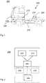
- Fig. 1 shows a side view of an electrically powered vehicle 300, comprising a power system 200, which in turn comprises a control unit 210
- the control unit 210 is configured to control distribution of electric power from a rechargeable energy storage system 220, such as at least one battery, to at least one electrical load 230.
- the at least one electrical load 230 may be one or more of an electrical propulsion system of the vehicle 300, or an auxiliary load, such as a thermal system, and/or a power take-off of the vehicle 300.
- a plurality of electrical loads 230 may be connected simultaneously and consume varying amounts of power delivered by the rechargeable energy storage system 220.
- Power take-offs such as electrical equipment, machines and tools may also be connected. Power distribution to these systems, i.e. to the electrical loads 230, may need to be derated by the control unit 210 under certain conditions of increased usage of the rechargeable energy storage system 220, in order to avoid impacting the State of Health of e.g. a battery of the rechargeable energy storage system 220.
- the control unit 210 is connected to other parts of the power system 200 of the electrically powered vehicle 300.
- the control unit 210 controls the distribution of power to or from the rechargeable energy storage system 220 to the at least one electrical load 230 via an interface 240.
- electrical loads 230 are depicted in dashed lines to illustrate that they may be an integrated part of the power system 200, or they may be auxiliary/external loads that are connectable to the power system 200 via the interface 240.
- the interface 240 may be exemplified by cables and buses, e.g. a traction voltage bus for a traction voltage system of an electric vehicle.
- the interface 240 may for instance be an electrical connector or an electric Power Take-Off (ePTO).
- the control unit 210 manages derating/limiting of power to the electrical load(s) 230 such energy consumption of the electrical load(s) 230 is controlled within certain limits, herein also called load thresholds, of the rechargeable energy storage system 220.
- a manufacturer of the rechargeable energy storage system 220 may provide the system with recommended limits/load thresholds for power outtake within which limits electrical load(s) 230 may operate to an extent. Within the limits, the manufacturer guarantees a certain lifetime of the rechargeable energy storage system 220.
- these limits may be set when configuring the system 220 during installation, such as when installing the rechargeable energy storage system 220 in a vehicle 300 having a particular set of electrical loads 230.
- the limits/load thresholds may also be set dynamically depending on operating conditions. Such operating conditions are usually known and may be pre-defined and detectable by the control unit 210 of the vehicle 300. The limits/load thresholds may be set appropriately according to the operating conditions combined with characteristics of the power system 200 its application, i.e. connected electrical loads 230.
- the present disclosure provides a method for optimizing the power ability of the rechargeable energy storage system 220, such that power is not needlessly kept in reserve. At the same time, the method minimizes an added impact to the State of Health of the system 220, which is due to an increased power outtake because the method allows the limit/load thresholds to be exceeded in a controlled manner.
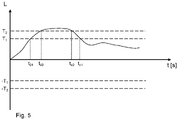
- Fig. 3 shows a flow chart of an exemplary embodiment according to the present disclosure. See also Fig. 5 , which shows a graph of an exemplary usage of the rechargeable energy storage system 220.
- a method 100 for determining a derating factor for a rechargeable energy storage system 220 is illustrated.
- the derating factor is indicative of the rate at which an electrical load 230, imparted on said rechargeable energy storage system 220, is reduced.
- the rechargeable energy storage system 220 is associated with at least a first load threshold T 1 and at least a second load threshold T 2 which is located further away from a zero electrical load value than the first load threshold T 1 .
- the method 100 comprises, for an operating time range of said rechargeable energy storage system 220, detecting 101 the electrical load 230, and when the electrical load 230 is equal to said electrical first load threshold T 1 or is located between said electrical first load threshold T 1 and said second load threshold T 2 , determining 102 an accumulated first load value L 1 indicative of the time during which, as well as the magnitude of how much, said electrical load extends from said first load threshold T 1 .
- the method further comprises determining 104 a safety margin value SM by combining said accumulated first load value L 1 and said accumulated second load value L 2 and relating the thus combined values with said operating time range, and comparing 105 said safety margin value SM to at least one safety margin threshold value SMT in order to determine whether or not said derating factor should be modified.
- the first load threshold T 1 and the second load threshold T 2 may be predetermined static thresholds or they may be determined dynamically in dependence of operating conditions of the rechargeable energy storage system 220. In the latter case, they may be determined at every time sample in order to provide optimal threshold values for the existing operating conditions.
- the step of detecting 101 the electrical load 230 may comprise the additional measure of determining a number, N, of additional load thresholds T 3 ...T N .
- the electrical load 230 is detected 101 as a positive electrical load 230, only positive load thresholds, i.e. +T n , are relevant for the method 100 for determining the derating factor, where T n indicates any particular load threshold used in the method.
- the electrical load 230 is detected 101 as a negative electrical load 230, only negative load thresholds, i.e. -T n , are relevant for the method 100 for determining the derating factor.
- the derating factor may either be increased, reduced or maintained in dependence of the determined safety margin value SM.
- An increased derating factor results in a stronger derating of the electrical load(s) 230 than previously, because the safety margin value SM indicates that the power ability of the rechargeable energy storage system 220 is being overused.
- a decreased derating factor results in a lower derating of the electrical load(s) 230 than previously, because the safety margin value SM indicates that the power ability of the rechargeable energy storage system 220 is not used enough.
- a maintained derating factor indicates that the rechargeable energy storage system 220 is being optimally used.
- a maintained derating factor still means that the electrical load D is being derated if detected further away from at least the zero electrical load value than the first load threshold T 1 , but at an optimal rate.
- the load value of the electrical load 230 is indicative of electric current, alternatively electric power.
- the electrical load 230 imparted on the rechargeable energy storage system 220 may be detected as current consumption, alternatively as power consumption by the electrical load 230 connected to, or comprised in, the rechargeable energy storage system 220.
- the operating time range during which the method is applied may be static and determined in advance. It may optionally be determined dynamically in dependence of operating conditions of the rechargeable energy storage system.
- the step of combining the accumulated first load value L 1 and the accumulated second load value L 2 , e.g. into an accumulated weighted load value L w may comprise multiplying the accumulated first load value L 1 by a first weight factor w 1 and multiplying the accumulated second load value L 2 by a second weight factor w 2 .
- a weight factor w n may be static a static weight factor for a corresponding load threshold T n .
- each weight factor w n may be determined dynamically at the time of determining the corresponding load threshold T n . In this way, the severity of exceeding any load threshold T n may appropriately affect the safety margin value SM.
- the derating factor will be determined such that exceeding higher load thresholds T n , in most scenarios, leads to a more severe derating of the electrical load(s) 230.
- a higher load threshold T n may be provided with a relatively low weight factor w n .
- the vertical axis shows how the load L on the electric energy storage system 220 varies over time t (horizontal axis).
- the load may be positive, such as when charging, or negative, such as when discharging the rechargeable energy storage system 220.
- the unit detected and evaluated for the electrical load 230 may for instance be current or power.
- the safety margin value SM may then optionally be calculated as the ratio between the accumulated weighted load value and the unweighted accumulated load value L w area, which equals the area between the plotted curve and the first load Threshold T 1 in Fig. 5 .
- SM L w L w area
- the derating factor may be determined by comparing 104 the safety margin value SM to at least one safety margin threshold value SMT. Thereby it is determined how severely to derate the electrical load(s) 230.
- the step of comparing 104 the safety margin value with the at least one safety margin threshold value SMT may, for instance, be carried out according to the example below.
- 1.0 ⁇ SM The derating factor is increased by a large factor because the State of Health may be affected 0.8 ⁇ SM ⁇ 1.0
- the derating factor is increased 0.5 ⁇ SM ⁇ 0.8
- the derating factor is maintained SM ⁇ 0.5
- the derating factor is decreased
- a method 400 of operating a rechargeable energy storage system 220 is associated with at least a first load threshold T 1 and at least a second load threshold T 2 , which is located further away from a zero electrical load value than the first load threshold T 1 .
- the method comprises determining 401 a current electrical load value for said rechargeable energy storage system 220.
- the method comprises derating 402 the at least one electrical load 230, using a derating factor at least until the electrical load value is located closer to the zero electrical load value than the first load threshold T 1 , wherein the derating factor is determined in accordance with any one of the steps according to the first aspect of the present disclosure, above.
- the electrical load value is determined 401 as a positive electrical load value, only positive load thresholds, i.e. +T n , are relevant for the method 400 for operating the rechargeable energy storage system 220.
- the electrical load value is determined 401 as a negative electrical load value, only negative load thresholds, i.e. -T n , are relevant for the method 400 for operating the rechargeable energy storage system 220.
- the electrical load value is repeatedly determined 401 as it varies during operation of the rechargeable energy storage system 220.
- the electrical load value is determined 401 to be equal to the first load threshold T 1 .
- the electrical load 230 is derated 402 using the derating factor.
- the electrical load value is equal to the second load threshold T 2 , whereupon the derating factor is either increased, maintained or decreased.
- the derating factor is increased when the electrical load value is determined to exceed a load threshold further away from the first load threshold T 1 , but there may be exceptions, as realized by a skilled person.
- the electrical load value is again closer to zero electrical load than the first load threshold T 1 and the electrical load 230 is no longer derated.
- the plurality of electrical loads 230 are derated 402 according to a dynamic or static priority list, using the derating factor, until the electrical load value of the plurality of electrical loads 230 is located closer to the zero electrical load value than the first load threshold T 1 .
- a dynamic priority list may in some situations prioritize a certain load, whereas in other situations the same load gets a low priority. Traction may, for instance be prioritized when a vehicle 300 is moving, whereas traction may not be prioritized at all when the vehicle is parked.
Landscapes
- Engineering & Computer Science (AREA)
- Power Engineering (AREA)
- Transportation (AREA)
- Mechanical Engineering (AREA)
- Life Sciences & Earth Sciences (AREA)
- Sustainable Development (AREA)
- Sustainable Energy (AREA)
- Charge And Discharge Circuits For Batteries Or The Like (AREA)
- Control Of Eletrric Generators (AREA)
- Steering Control In Accordance With Driving Conditions (AREA)
Abstract
Description
- The present disclosure relates to a method for determining a derating factor for a rechargeable energy storage system and to a method for operating a rechargeable energy storage system. The present disclosure also relates to a control unit configured to monitor and control an electrical load, a computer program, a computer readable medium, a power system comprising the control unit and an electrically powered vehicle or vessel comprising the control unit and/or the power system.
- Rechargeable Energy Storage Systems (RESS) require special consideration for controlling power outtake, especially during transient conditions, to avoid impacting the State of Health (SoH) of the storage system, e.g. batteries. This is particularly true for applications using a rechargeable energy storage system for traction of vehicles or marine vessels, but it may also be required for other applications where a rechargeable energy storage system frequently supplies electrical loads, such as gensets and similar systems.
- Attempts have been made to extend battery life in vehicles.
JP2005218171 - However, it would be desired to further refine the control methods for electrical loads.
- Therefore, an object of the disclosure is to provide a method for determining a derating factor for a rechargeable energy storage system. More specifically, an object of the disclosure is to provide a method allowing appropriate use of buffer zones of a rechargeable energy storage system without unnecessarily limiting electrical loads and without unnecessarily impacting the State of Health of the rechargeable energy storage system. Another object of the disclosure is to provide a method for operating the rechargeable energy storage system. Further aspects of the disclosure are to provide a control unit for controlling electrical loads according to the method, to provide a power system comprising the control unit and to provide a vehicle or a vessel comprising the control unit and/or the power system.
- According to a first aspect of the disclosure the object is achieved by a method for determining a derating factor for a rechargeable energy storage system. The derating factor is indicative of the rate at which an electrical load, imparted on said rechargeable energy storage system, is reduced. The rechargeable energy storage system is associated with at least a first load threshold and at least a second load threshold which is located further away from a zero electrical load value than the first load threshold. The method comprises
- for an operating time range of the rechargeable energy storage system, detecting the electrical load and:
- ∘ when the electrical load is equal to the first load threshold or is located between the electrical first load threshold and the second load threshold, determining an accumulated first load value indicative of the time during which, as well as the magnitude of how much, the electrical load extends from the first load threshold,
- ∘ when the electrical load is equal to said second load threshold or is located further away from a zero electrical load value than the second load threshold, determining an accumulated second load value indicative of the time during which, as well as the magnitude of how much, the electrical load extends from the second load threshold,
- determining a safety margin value by combining the accumulated first load value and the accumulated second load value and relating the thus combined values with the operating time range, and
- comparing the safety margin value to at least one safety margin threshold value in order to determine whether or not the derating factor should be modified.
- The electrical load is a consumer of electric power/current connected to the rechargeable energy storage system. The detected electrical load may have a positive or a negative value depending on whether the rechargeable energy storage system is charging or discharging. Thus, when the value of the electrical load is located away from the zero electrical load value, the value may be either positive or negative. It follows that any load thresholds may also be positive or negative.
- A load threshold according to the present disclosure represents a load value at, or beyond, which the derating factor is determined and used, i.e. at or beyond which the electrical load is derated. If the load value is detected between the zero electrical load value and the first load threshold, derating is unnecessary.
- The first load threshold thus defines a lower threshold of a first buffer of the rechargeable energy storage system, where the electrical load and any load thresholds may be either positive or negative. Any further load thresholds farther away from the zero electrical load value than the first load threshold constitute lower limits of respective further buffers. Accordingly, the second load threshold defines a lower limit of a second buffer. The second load threshold also defines an upper limit of the first buffer. The lower limit of a buffer is closer to the zero electrical load value than the upper limit of the same buffer. The limits of the buffers, i.e. the load thresholds, may be set by the manufacturer of the rechargeable energy storage system, but they may also be set and/or modified by a control unit of the system depending on operating conditions, or depending on the detected electrical load of the system. For instance, a high detected load value may generate further load thresholds and buffers.
- The derating factor is a factor that is used to limit an electrical load of the rechargeable energy storage system in order to minimize State of Health degradation, where "State of Health", or SoH, is a measure of the condition of a rechargeable energy storage system, such as a battery. By determining the derating factor according to the method of the present disclosure there is provided a possibility of controlling an electrical load connected to the system in a dynamical manner to return potentially damaging power/current consumption to acceptable consumption. The electrical load is allowed to use any buffers of the rechargeable energy storage system to an extent. If the buffers are used marginally, and/or for short periods of time, the derating factor may be decreased to only slowly derate the load. On the other hand, if the load values increase quickly, or if they exceed one of the load thresholds for a longer time, the derating factor will be increased to derate the load faster and return to a load value between the zero electrical load value and the first load threshold. The buffers may thus be used in a more efficient way while protecting the State of Health of the rechargeable energy storage system. In addition, the need to reserve a part of the system's power capability for transients is also reduced.
- The safety margin value is an indication of the magnitude of the use of the buffers over time and determines whether or not the derating factor should be modified.
- Optionally, a high safety margin value yields an increased derating factor, a moderate safety margin value yields a maintained derating factor, and a low safety margin value may yield a reduced derating factor. Also, a very high safety factor may significantly increase the derating factor to quickly return the electrical load to acceptable, i.e. non-harmful, levels.
- Optionally, the electrical load is indicative of electric current, alternatively electric power. The electrical load is an electrical component or system connected to the rechargeable energy storage system. Detection of the electrical load may therefore be synonymous to detecting current consumption or power consumption of the system. Consequently, derating the electrical load may mean to control operation of the load, e.g. consumption of the load, to a level lower than its maximum capacity. Under some conditions, derating the electrical load may mean to turn off/switch off the load completely.
- Optionally, the feature of combining said accumulated first load value and said accumulated second load value comprises multiplying said accumulated first load value by a first weight factor and multiplying said accumulated second load value by a second weight factor. The weight factors determine the significance of the accumulated first and second load values in view of the State of Health of the rechargeable energy storage system. Exceeding a load threshold may therefore affect the derating factor to greater or lesser degree depending on the weight factor associated with said load threshold (i.e. buffer).
- Optionally, the first weight factor and the second weight factor are determined dynamically in dependence of operating conditions. In this manner, exceeding a certain load threshold may be more or less acceptable in some operating conditions of the rechargeable energy storage system as compared to other operating conditions. Operating conditions herein mean conditions under which the rechargeable energy storage system operates, such as weather, ambient temperature, temperature of the rechargeable energy storage system, characteristics of connected electrical loads, inclination of a vehicle comprising the rechargeable energy storage system, etc.
- Optionally, the operating time range and/or said at least first load threshold and second load threshold are determined dynamically in dependence of operating conditions of the rechargeable energy storage system. Similarly to the above, the load thresholds and the operating time range may be set dynamically, such that buffer zones in which the electrical load is derated are determined dynamically. Accordingly, if some operating conditions allow a greater or smaller part of the rechargeable energy storage system to be used without harmful effects, the dynamical setting of the buffers allows a more efficient use of the rechargeable energy storage system.
- According to second aspect of the present disclosure, there is provided a method for operating a rechargeable energy storage system. The rechargeable energy storage system is associated with at least a first load threshold and at least a second load threshold which is located further away from a zero electrical load value than the first load threshold. The method comprises
- determining a current electrical load value for said rechargeable energy storage system, and
- if the current electrical load value is equal to first load threshold, or located further away from the zero electrical load value than the first load threshold, derating the at least one electrical load, using a derating factor at least until the electrical load value is located closer to the zero electrical load value than the first load threshold, wherein the derating factor has been determined in accordance with the method of the first aspect of the present disclosure.
- In accordance with the above, when the electrical load is detected at a level which may be harmful to the rechargeable energy storage system, operation of the electrical load is limited (derated) towards a level which is closer to the zero electrical load value, i.e. towards a lower current or power consumption of the component of system connected to the rechargeable energy storage system. This reduces the impact of high current or power consumption on the State of Health of the rechargeable energy storage system.
- Optionally, the feature of derating a plurality of electrical loads, the plurality of electrical loads are derated according to a dynamic or static priority list, using the derating factor, until the electrical load value of the plurality of electrical loads is located closer to said zero electrical load value than said first load threshold. The electrical load of the rechargeable energy storage system is the total load connected to the system. The term "electrical load" may thus mean a plurality of electrical loads, i.e. electric equipment, components or systems, which are connected to the rechargeable energy storage system. If more than one electrical load needs to be derated, the provision of a priority list, either dynamic or static, allows more important components or equipment to keep operating at normal capacity, while other components or equipment are derated, or even switched off.
- According to a third aspect of the present disclosure, there is provided a control unit configured to monitor and control at least one electrical load imparted on a rechargeable energy storage system according to the steps of the first and/or second aspects of the present disclosure.
- The control unit is provided with processing capability and may be connected to sensors and measurement systems for determining operating conditions rechargeable energy storage system. The control unit further controls the distribution of power from the electric energy storage system to the electrical load and administers the derating of the electrical load. In other words, the control unit controls the determination of the derating factor and the derating of the electrical load.
- The control unit may also be connected to a computer readable medium having stored thereon a computer program, which comprises code to cause the control unit to execute any of the method steps of the present disclosure.
- According to a fourth aspect of the present disclosure, there is provided a power system which comprises a control unit according to the third aspect of the present disclosure, a rechargeable energy storage system, and an interface connectable to at least one electrical load. Optionally, the power system further comprises the at least one electrical load.
- The power system may be a power system of a fully or partly electrically powered vehicle or vessel, such as a marine vessel having one or more on-board electrical loads. Alternatively, the power system may be a stand-alone power system, such as a stationary or mobile rechargeable genset, which may be used where power is needed, for instance in places where power outages are frequent, and/or where an outage can cause especially significant or dangerous problems, such as in a mine or in a hospital. In such situations, external electrical loads need to be supplied with power from the power system.
- According to a fifth aspect of the present disclosure, there is provided an electrically powered vehicle or vessel comprising the control unit and/or the power system of the present disclosure.
- Further objects and advantages of, and features of the disclosure will be apparent from the following description of one or more embodiments, with reference to the appended drawings, where:
- Fig. 1
- shows a vehicle comprising a power system of the present disclosure
- Fig. 2
- shows a schematic view of a power system according to the present disclosure
- Fig. 3
- shows flowchart of a method according to a first aspect of the present disclosure
- Fig. 4
- shows a flowchart of a method according to a second aspect of the present disclosure
- Fig. 5
- shows an exemplary application of the method of
Fig. 4 - The present disclosure is developed in more detail below referring to the appended drawings which show examples of embodiments. The disclosure should not be viewed as limited to the described examples of embodiments; instead, it is defined by the appended patent claims. Like numbers refer to like elements throughout the description.
-
Fig. 1 shows a side view of an electricallypowered vehicle 300, comprising apower system 200, which in turn comprises acontrol unit 210 Thecontrol unit 210 is configured to control distribution of electric power from a rechargeableenergy storage system 220, such as at least one battery, to at least oneelectrical load 230. The at least oneelectrical load 230 may be one or more of an electrical propulsion system of thevehicle 300, or an auxiliary load, such as a thermal system, and/or a power take-off of thevehicle 300. As shown inFig. 1 , a plurality ofelectrical loads 230 may be connected simultaneously and consume varying amounts of power delivered by the rechargeableenergy storage system 220. There may be thermal systems for heating or cooling of a cab or of a cargo hold of thevehicle 300. Power take-offs, such as electrical equipment, machines and tools may also be connected. Power distribution to these systems, i.e. to theelectrical loads 230, may need to be derated by thecontrol unit 210 under certain conditions of increased usage of the rechargeableenergy storage system 220, in order to avoid impacting the State of Health of e.g. a battery of the rechargeableenergy storage system 220. - As shown in
Fig. 2 , thecontrol unit 210 is connected to other parts of thepower system 200 of the electricallypowered vehicle 300. Thecontrol unit 210 controls the distribution of power to or from the rechargeableenergy storage system 220 to the at least oneelectrical load 230 via aninterface 240. InFig. 2 ,electrical loads 230 are depicted in dashed lines to illustrate that they may be an integrated part of thepower system 200, or they may be auxiliary/external loads that are connectable to thepower system 200 via theinterface 240. For integratedelectrical loads 230, theinterface 240 may be exemplified by cables and buses, e.g. a traction voltage bus for a traction voltage system of an electric vehicle. For auxiliary loads, theinterface 240 may for instance be an electrical connector or an electric Power Take-Off (ePTO). - To ensure that the at least one
electrical load 230 does not overuse the capability of the rechargeableenergy storage system 220, thecontrol unit 210 manages derating/limiting of power to the electrical load(s) 230 such energy consumption of the electrical load(s) 230 is controlled within certain limits, herein also called load thresholds, of the rechargeableenergy storage system 220. A manufacturer of the rechargeableenergy storage system 220 may provide the system with recommended limits/load thresholds for power outtake within which limits electrical load(s) 230 may operate to an extent. Within the limits, the manufacturer guarantees a certain lifetime of the rechargeableenergy storage system 220. In order to optimize usage of rechargeableenergy storage system 220 for a certain application, these limits may be set when configuring thesystem 220 during installation, such as when installing the rechargeableenergy storage system 220 in avehicle 300 having a particular set ofelectrical loads 230. The limits/load thresholds may also be set dynamically depending on operating conditions. Such operating conditions are usually known and may be pre-defined and detectable by thecontrol unit 210 of thevehicle 300. The limits/load thresholds may be set appropriately according to the operating conditions combined with characteristics of thepower system 200 its application, i.e. connectedelectrical loads 230. - The present disclosure provides a method for optimizing the power ability of the rechargeable
energy storage system 220, such that power is not needlessly kept in reserve. At the same time, the method minimizes an added impact to the State of Health of thesystem 220, which is due to an increased power outtake because the method allows the limit/load thresholds to be exceeded in a controlled manner. -
Fig. 3 shows a flow chart of an exemplary embodiment according to the present disclosure. See alsoFig. 5 , which shows a graph of an exemplary usage of the rechargeableenergy storage system 220. Amethod 100 for determining a derating factor for a rechargeableenergy storage system 220 is illustrated. The derating factor is indicative of the rate at which anelectrical load 230, imparted on said rechargeableenergy storage system 220, is reduced. The rechargeableenergy storage system 220 is associated with at least a first load threshold T1 and at least a second load threshold T2 which is located further away from a zero electrical load value than the first load threshold T1. Themethod 100 comprises, for an operating time range of said rechargeableenergy storage system 220, detecting 101 theelectrical load 230, and when theelectrical load 230 is equal to said electrical first load threshold T1 or is located between said electrical first load threshold T1 and said second load threshold T2, determining 102 an accumulated first load value L1 indicative of the time during which, as well as the magnitude of how much, said electrical load extends from said first load threshold T1. When theelectrical load 230 is equal to the second load threshold T2 or is located further away from a zero electrical load value than said second load threshold T2, determining 103 an accumulated second load value L2 indicative of the time during which, as well as the magnitude of how much, saidelectrical load 230 extends from said second load threshold T2. The method further comprises determining 104 a safety margin value SM by combining said accumulated first load value L1 and said accumulated second load value L2 and relating the thus combined values with said operating time range, and comparing 105 said safety margin value SM to at least one safety margin threshold value SMT in order to determine whether or not said derating factor should be modified. - Thus, as outlined hereinbefore, the first load threshold T1 and the second load threshold T2 may be predetermined static thresholds or they may be determined dynamically in dependence of operating conditions of the rechargeable
energy storage system 220. In the latter case, they may be determined at every time sample in order to provide optimal threshold values for the existing operating conditions. - In the exemplary embodiment of
Fig. 3 , at least two load thresholds T1, T2 are disclosed, but any further number of thresholds may be employed. The step of detecting 101 theelectrical load 230 may comprise the additional measure of determining a number, N, of additional load thresholds T3...TN. - Obviously, if the
electrical load 230 is detected 101 as a positiveelectrical load 230, only positive load thresholds, i.e. +Tn, are relevant for themethod 100 for determining the derating factor, where Tn indicates any particular load threshold used in the method. Similarly, if theelectrical load 230 is detected 101 as a negativeelectrical load 230, only negative load thresholds, i.e. -Tn, are relevant for themethod 100 for determining the derating factor. - The derating factor may either be increased, reduced or maintained in dependence of the determined safety margin value SM. An increased derating factor results in a stronger derating of the electrical load(s) 230 than previously, because the safety margin value SM indicates that the power ability of the rechargeable
energy storage system 220 is being overused. A decreased derating factor results in a lower derating of the electrical load(s) 230 than previously, because the safety margin value SM indicates that the power ability of the rechargeableenergy storage system 220 is not used enough. A maintained derating factor indicates that the rechargeableenergy storage system 220 is being optimally used. A maintained derating factor still means that the electrical load D is being derated if detected further away from at least the zero electrical load value than the first load threshold T1, but at an optimal rate. - The load value of the
electrical load 230 is indicative of electric current, alternatively electric power. In other words, theelectrical load 230 imparted on the rechargeableenergy storage system 220 may be detected as current consumption, alternatively as power consumption by theelectrical load 230 connected to, or comprised in, the rechargeableenergy storage system 220. - The operating time range during which the method is applied may be static and determined in advance. It may optionally be determined dynamically in dependence of operating conditions of the rechargeable energy storage system.
- The step of combining the accumulated first load value L1 and the accumulated second load value L2, e.g. into an accumulated weighted load value Lw , may comprise multiplying the accumulated first load value L1 by a first weight factor w1 and multiplying the accumulated second load value L2 by a second weight factor w2 . A weight factor wn may be static a static weight factor for a corresponding load threshold Tn. Alternatively, each weight factor wn may be determined dynamically at the time of determining the corresponding load threshold Tn. In this way, the severity of exceeding any load threshold Tn may appropriately affect the safety margin value SM. Consequently, the derating factor will be determined such that exceeding higher load thresholds Tn, in most scenarios, leads to a more severe derating of the electrical load(s) 230. However, under some conditions it is conceivable that a higher load threshold Tn may be provided with a relatively low weight factor wn.
- As an example of the method illustrated in
Fig. 3 , the steps may be carried out using the algorithms below. This is further illustrated inFig. 5 . The vertical axis shows how the load L on the electricenergy storage system 220 varies over time t (horizontal axis). The load may be positive, such as when charging, or negative, such as when discharging the rechargeableenergy storage system 220. The unit detected and evaluated for theelectrical load 230 may for instance be current or power. - When the current exceeds the first load threshold T1, either when charging or discharging, there is a need to start evaluating the
electrical load 230 to not overuse the rechargeableenergy storage system 220 and thereby utilize additional State of Health. - The accumulated first load value L1 may be determined by

- L1
- The accumulated first load value
- t01
- The time when the first load threshold T1, is exceeded and a load value beyond the first load threshold T1 is detected
- tc1
- The time when the first load threshold T1, is subceeded and a load value beyond the first load threshold T1 is not detected anymore
- Lcurrent,t
- Actual load value at time sample t
- T1,t
- Actual first load threshold T1 (value) at time sample t
- When the current exceeds the second load threshold T2, either when charging or discharging, there is a stronger need to start evaluating the electrical load to not overuse the rechargeable
energy storage system 220 and thereby utilizing the rechargeableenergy storage system 220 without affecting the State of Health to a larger extent. - The accumulated second load value L2 may be determined by
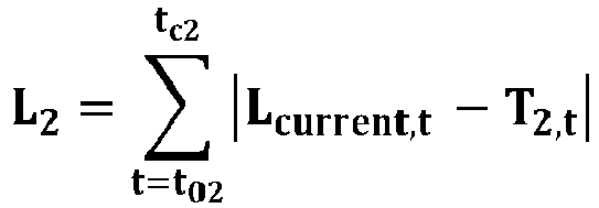
- L2
- The accumulated first load value
- t02
- The time when the second load threshold T2, is exceeded and a load value beyond the second load threshold T2 is detected
- tc2
- The time when the first load threshold T2, is subceeded and a load value beyond the first load threshold T2 is not detected anymore
- Lcurrent,t
- Actual load value at time sample t
- T2, t
- Actual first load threshold T1 (value) at time sample t
- The accumulated first load value L1 and the accumulated second load value L2 may optionally be weighted to reflect the severity of exceeding in the first load threshold T1 and the second load threshold T2, respectively. This yields the accumulated weighted load value Lw:

- Lw
- The accumulated weighted load value
- w1
- Weight factor for exceeding the first load threshold T1
- w2
- Weight factor for exceeding the first load threshold T2
- The safety margin value SM may then optionally be calculated as the ratio between the accumulated weighted load value and the unweighted accumulated load value Lwarea, which equals the area between the plotted curve and the first load Threshold T1 in
Fig. 5 .
- Lw area
- The unweighted accumulated load value (L1 + L2)
- When the safety margin value SM is determined 103 the derating factor may be determined by comparing 104 the safety margin value SM to at least one safety margin threshold value SMT. Thereby it is determined how severely to derate the electrical load(s) 230. The step of comparing 104 the safety margin value with the at least one safety margin threshold value SMT may, for instance, be carried out according to the example below.
1.0 ≤ SM The derating factor is increased by a large factor because the State of Health may be affected 0.8 ≤ SM < 1.0 The derating factor is increased 0.5 ≤ SM < 0.8 The derating factor is maintained SM < 0.5 The derating factor is decreased - According to a second aspect of the present disclosure, shown in
Fig. 4 , there is also provided amethod 400 of operating a rechargeableenergy storage system 220. The rechargeableenergy storage system 220 is associated with at least a first load threshold T1 and at least a second load threshold T2, which is located further away from a zero electrical load value than the first load threshold T1. The method comprises determining 401 a current electrical load value for said rechargeableenergy storage system 220. If the current electrical load value is equal to the first load threshold T1, or located further away from the zero electrical load value than the first load threshold T1, the method comprises derating 402 the at least oneelectrical load 230, using a derating factor at least until the electrical load value is located closer to the zero electrical load value than the first load threshold T1, wherein the derating factor is determined in accordance with any one of the steps according to the first aspect of the present disclosure, above. - Obviously, if the electrical load value is determined 401 as a positive electrical load value, only positive load thresholds, i.e. +Tn, are relevant for the
method 400 for operating the rechargeableenergy storage system 220. Similarly, if the electrical load value is determined 401 as a negative electrical load value, only negative load thresholds, i.e. -Tn, are relevant for themethod 400 for operating the rechargeableenergy storage system 220. - As illustrated in the flow chart of
Fig. 4 and the example ofFig. 5 , the electrical load value is repeatedly determined 401 as it varies during operation of the rechargeableenergy storage system 220. At t01, the electrical load value is determined 401 to be equal to the first load threshold T1. As it continues to rise, theelectrical load 230 is derated 402 using the derating factor. At t02, the electrical load value is equal to the second load threshold T2, whereupon the derating factor is either increased, maintained or decreased. In most scenarios, the derating factor is increased when the electrical load value is determined to exceed a load threshold further away from the first load threshold T1, but there may be exceptions, as realized by a skilled person. - At tc1, the electrical load value is again closer to zero electrical load than the first load threshold T1 and the
electrical load 230 is no longer derated. - In the case of a plurality of
electrical loads 230, the plurality ofelectrical loads 230 are derated 402 according to a dynamic or static priority list, using the derating factor, until the electrical load value of the plurality ofelectrical loads 230 is located closer to the zero electrical load value than the first load threshold T1. A dynamic priority list may in some situations prioritize a certain load, whereas in other situations the same load gets a low priority. Traction may, for instance be prioritized when avehicle 300 is moving, whereas traction may not be prioritized at all when the vehicle is parked. - Modifications and other embodiments of the disclosed embodiments will come to mind to one skilled in the art having the benefit of the teachings presented in the foregoing descriptions and the associated drawings. Therefore, it is to be understood that the embodiment(s) is/are not to be limited to the specific embodiments disclosed and that modifications and other embodiments are intended to be included within the scope of this disclosure. Although specific terms may be employed herein, they are used in a generic and descriptive sense only and not for purposes of limitation.
Claims (14)
- A method (100) for determining a derating factor for a rechargeable energy storage system (220), said derating factor being indicative of the rate at which an electrical load (230), imparted on said rechargeable energy storage system, is reduced, said rechargeable energy storage system (220) being associated with at least a first load threshold (T1) and at least a second load threshold (T2) being located further away from a zero electrical load value than the first load threshold (T1), the method comprising:- for an operating time range of said rechargeable energy storage system (220), detecting (101) said electrical load (230) and:∘ when said electrical load (230) is equal to said electrical first load threshold (T1) or is located between said electrical first load threshold (T1) and said second load threshold (T2), determining (102) an accumulated first load value (L1) indicative of the time during which, as well as the magnitude of how much, said electrical load (230) extends from said first load threshold (T1),∘ when said electrical load (230) is equal to said second load threshold (T2) or is located further away from a zero electrical load value than said second load threshold (T2), determining (103) an accumulated second load value (L2) indicative of the time during which, as well as the magnitude of how much, said electrical load (230) extends from said second load threshold (T2),- determining (104) a safety margin value (SM) by combining said accumulated first load value (L1) and said accumulated second load value (L2) and relating the thus combined values with said operating time range, and- comparing (105) said safety margin value (SM) to at least one safety margin threshold value (SMT) in order to determine whether or not said derating factor should be modified.
- The method according to claim 1, wherein the derating factor is either increased, reduced or maintained in dependence of the determined safety margin value (SM).
- The method according to any one of the preceding claims, wherein said electrical load (230) is indicative of electric current, alternatively electric power.
- The method according to any one of the preceding claims, wherein said feature of combining said accumulated first load value (L1) and said accumulated second load value (L2) comprises multiplying said accumulated first load value (L1) by a first weight factor (w1) and multiplying said accumulated second load value (L2) by a second weight factor (w2).
- The method according to claim 4, wherein the first weight factor (w1) and the second weight factor (w2) are determined dynamically in dependence of operating conditions.
- The method according to any one of the preceding claims, wherein said operating time range and/or said at least first load threshold (T1) and second load threshold (T2) are determined dynamically in dependence of operating conditions of the rechargeable energy storage system (220).
- A method (400) for operating a rechargeable energy storage system (220), the rechargeable energy storage system (220) being associated with at least a first load threshold (T1) and at least a second load threshold (T2) being located further away from a zero electrical load value than the first load threshold (T1), the method (400) comprising:- determining (401) a current electrical load value for said rechargeable energy storage system (220), and- if the current electrical load value is equal to said first load threshold (T1) or, located further away from said zero electrical load value than said first load threshold (T1), derating (402) the at least one electrical load (230), using a derating factor at least until the electrical load value is located closer to said zero electrical load value than said first load threshold (T1), wherein said derating factor has been determined in accordance with any one of the preceding claims.
- The method according to claim 7, wherein for the step of derating (402) a plurality of electrical loads (230), the plurality of electrical loads (230) are derated according to a dynamic or static priority list, using the derating factor, until the electrical load value of the plurality of electrical loads (230) is located closer to said zero electrical load value than said first load threshold (T1).
- A control unit (210) configured to monitor and control at least one electrical load (230) imparted on a rechargeable energy storage system (220) according to the steps of any one of the claims 1 - 8.
- A computer program comprising program code to cause the control unit (210) of claim 9 to execute the steps of any one of the claims 1 - 8.
- A computer readable medium having stored thereon the computer program of claim 10.
- A power system (200) comprising:- a control unit (210) according to claim 9,- a rechargeable energy storage system (220),- an interface (240) connectable to at least one electrical load (230).
- The power system (200) according to claim 12, further comprising at least one electrical load (230).
- An at least partly electrically powered vehicle or vessel (300) comprising the power system (200) according to any one of the claims 12 - 13.
Priority Applications (4)
| Application Number | Priority Date | Filing Date | Title |
|---|---|---|---|
| EP21161700.6A EP4056414A1 (en) | 2021-03-10 | 2021-03-10 | A method for determining a derating factor of an energy storage system, a control unit, a power system and a vehicle |
| US17/653,381 US12227105B2 (en) | 2021-03-10 | 2022-03-03 | Method for determining a derating factor, a control unit, a power system and a vehicle |
| KR1020220028557A KR20220127160A (en) | 2021-03-10 | 2022-03-07 | A method for determining a derating factor, a control unit, a power system and a vehicle |
| CN202210231480.7A CN115071499A (en) | 2021-03-10 | 2022-03-09 | Method for determining derating factor, control unit, power system and vehicle |
Applications Claiming Priority (1)
| Application Number | Priority Date | Filing Date | Title |
|---|---|---|---|
| EP21161700.6A EP4056414A1 (en) | 2021-03-10 | 2021-03-10 | A method for determining a derating factor of an energy storage system, a control unit, a power system and a vehicle |
Publications (1)
| Publication Number | Publication Date |
|---|---|
| EP4056414A1 true EP4056414A1 (en) | 2022-09-14 |
Family
ID=74870675
Family Applications (1)
| Application Number | Title | Priority Date | Filing Date |
|---|---|---|---|
| EP21161700.6A Pending EP4056414A1 (en) | 2021-03-10 | 2021-03-10 | A method for determining a derating factor of an energy storage system, a control unit, a power system and a vehicle |
Country Status (4)
| Country | Link |
|---|---|
| US (1) | US12227105B2 (en) |
| EP (1) | EP4056414A1 (en) |
| KR (1) | KR20220127160A (en) |
| CN (1) | CN115071499A (en) |
Cited By (1)
| Publication number | Priority date | Publication date | Assignee | Title |
|---|---|---|---|---|
| FR3139913A1 (en) * | 2022-09-19 | 2024-03-22 | Psa Automobiles Sa | ACCURATE ESTIMATION OF THE MAXIMUM OPERATING POWER OF A VEHICLE CELL BATTERY |
Families Citing this family (1)
| Publication number | Priority date | Publication date | Assignee | Title |
|---|---|---|---|---|
| EP4056414A1 (en) * | 2021-03-10 | 2022-09-14 | Volvo Truck Corporation | A method for determining a derating factor of an energy storage system, a control unit, a power system and a vehicle |
Citations (4)
| Publication number | Priority date | Publication date | Assignee | Title |
|---|---|---|---|---|
| JP2005218171A (en) | 2004-01-27 | 2005-08-11 | Auto Network Gijutsu Kenkyusho:Kk | Power supply method from battery to load, power supply control device, and automobile |
| US20140183938A1 (en) * | 2012-12-30 | 2014-07-03 | Sanjay Peswani | System and method for derating a power limit associated with a battery pack |
| WO2020043775A1 (en) * | 2018-08-28 | 2020-03-05 | Robert Bosch Gmbh | Vehicle control system, method, apparatus and device |
| KR20200066476A (en) * | 2018-11-30 | 2020-06-10 | 현대자동차주식회사 | System and method of controlling battery power output for a eco-friendly vehicle |
Family Cites Families (10)
| Publication number | Priority date | Publication date | Assignee | Title |
|---|---|---|---|---|
| US4313080A (en) * | 1978-05-22 | 1982-01-26 | Battery Development Corporation | Method of charge control for vehicle hybrid drive batteries |
| US6417668B1 (en) * | 2001-01-31 | 2002-07-09 | International Truck International Property Company, L.L.C. | Vehicle battery condition monitoring system |
| US6946818B2 (en) * | 2003-10-14 | 2005-09-20 | General Motors Corporation | Method of determining battery power limits for an energy storage system of a hybrid electric vehicle |
| US8049460B2 (en) * | 2007-07-18 | 2011-11-01 | Tesla Motors, Inc. | Voltage dividing vehicle heater system and method |
| JP5447170B2 (en) * | 2010-05-13 | 2014-03-19 | トヨタ自動車株式会社 | Storage device control device and vehicle equipped with the same |
| EP2388902B1 (en) * | 2010-05-21 | 2013-08-14 | C.R.F. Società Consortile per Azioni | System and method for digital control of a DC/DC power-converter device, in particular for automotive applications |
| US10027145B2 (en) * | 2015-12-08 | 2018-07-17 | Hyundai Motor Company | Method for adjusting a voltage of battery by measuring a voltage decrease speed of battery |
| KR20180063613A (en) * | 2016-12-02 | 2018-06-12 | 현대자동차주식회사 | Vehicle, and Control Method of Vehicle |
| US11038336B1 (en) * | 2019-10-13 | 2021-06-15 | Schweitzer Engineering Laboratories, Inc. | Redundant power module and discharge circuit for improved substation device availability |
| EP4056414A1 (en) * | 2021-03-10 | 2022-09-14 | Volvo Truck Corporation | A method for determining a derating factor of an energy storage system, a control unit, a power system and a vehicle |
-
2021
- 2021-03-10 EP EP21161700.6A patent/EP4056414A1/en active Pending
-
2022
- 2022-03-03 US US17/653,381 patent/US12227105B2/en active Active
- 2022-03-07 KR KR1020220028557A patent/KR20220127160A/en active Pending
- 2022-03-09 CN CN202210231480.7A patent/CN115071499A/en active Pending
Patent Citations (4)
| Publication number | Priority date | Publication date | Assignee | Title |
|---|---|---|---|---|
| JP2005218171A (en) | 2004-01-27 | 2005-08-11 | Auto Network Gijutsu Kenkyusho:Kk | Power supply method from battery to load, power supply control device, and automobile |
| US20140183938A1 (en) * | 2012-12-30 | 2014-07-03 | Sanjay Peswani | System and method for derating a power limit associated with a battery pack |
| WO2020043775A1 (en) * | 2018-08-28 | 2020-03-05 | Robert Bosch Gmbh | Vehicle control system, method, apparatus and device |
| KR20200066476A (en) * | 2018-11-30 | 2020-06-10 | 현대자동차주식회사 | System and method of controlling battery power output for a eco-friendly vehicle |
Cited By (2)
| Publication number | Priority date | Publication date | Assignee | Title |
|---|---|---|---|---|
| FR3139913A1 (en) * | 2022-09-19 | 2024-03-22 | Psa Automobiles Sa | ACCURATE ESTIMATION OF THE MAXIMUM OPERATING POWER OF A VEHICLE CELL BATTERY |
| WO2024062167A1 (en) * | 2022-09-19 | 2024-03-28 | Stellantis Auto Sas | Method for accurately estimating the maximum operating power of a cellular battery of a vehicle |
Also Published As
| Publication number | Publication date |
|---|---|
| US12227105B2 (en) | 2025-02-18 |
| CN115071499A (en) | 2022-09-20 |
| KR20220127160A (en) | 2022-09-19 |
| US20220289071A1 (en) | 2022-09-15 |
Similar Documents
| Publication | Publication Date | Title |
|---|---|---|
| US20170120766A1 (en) | Apparatus And Method For Regulating A State Of Charge Of An Electrical Energy Store | |
| US7710067B2 (en) | Power supply system and power supply system control method | |
| CN106864280B (en) | Method and system for controlling voltage in stop mode of fuel cell vehicle | |
| EP2988965B1 (en) | Onboard charging system and control method thereof | |
| US12227105B2 (en) | Method for determining a derating factor, a control unit, a power system and a vehicle | |
| US10985586B2 (en) | Electric power supply system of electrical vehicle | |
| US11453305B2 (en) | Vehicle charge system and charge control method | |
| US10076972B2 (en) | Vehicle-electrical-system assembly and method for operating a vehicle electrical system of an electrically drivable means of transportation having a fuel cell | |
| CN111509331B (en) | Control method and device for cooling power battery and electric vehicle | |
| US11325497B2 (en) | Vehicle electricity supply control system | |
| KR101624644B1 (en) | System and method for derating a power limit associated with a battery pack | |
| US10752127B1 (en) | Battery controller and method of battery control | |
| EP3932726B1 (en) | A method of power management and a power system of an electrically powered vehicle | |
| KR100847527B1 (en) | Control apparatus for selectively controlling output current and output voltage of electric generator | |
| US12467978B2 (en) | Power-saving type apparatus and method for managing battery | |
| CN106043287B (en) | System and method for controlling LDC of hybrid vehicle | |
| CN111746346B (en) | Power supply system | |
| CN113320438A (en) | Storage battery charging method and device, readable storage medium and vehicle | |
| US9733658B2 (en) | Current protection for an electrical distribution component in an electrified vehicle | |
| JP2007018871A (en) | Secondary battery control device and system equipped with this device | |
| US20230191872A1 (en) | Method for Controlling a Heating/Air-Conditioning Component | |
| US12384257B2 (en) | Vehicle controller for reduction of power consumption while towing | |
| EP4230470B1 (en) | System and method for controlling output of a system powered by a battery and a fuel-cell | |
| KR20100063347A (en) | Battery management method of a hybrid car | |
| EP4693799A1 (en) | Control device and method for determining allowable output power of battery |
Legal Events
| Date | Code | Title | Description |
|---|---|---|---|
| PUAI | Public reference made under article 153(3) epc to a published international application that has entered the european phase |
Free format text: ORIGINAL CODE: 0009012 |
|
| STAA | Information on the status of an ep patent application or granted ep patent |
Free format text: STATUS: THE APPLICATION HAS BEEN PUBLISHED |
|
| AK | Designated contracting states |
Kind code of ref document: A1 Designated state(s): AL AT BE BG CH CY CZ DE DK EE ES FI FR GB GR HR HU IE IS IT LI LT LU LV MC MK MT NL NO PL PT RO RS SE SI SK SM TR |
|
| STAA | Information on the status of an ep patent application or granted ep patent |
Free format text: STATUS: REQUEST FOR EXAMINATION WAS MADE |
|
| 17P | Request for examination filed |
Effective date: 20230309 |
|
| RBV | Designated contracting states (corrected) |
Designated state(s): AL AT BE BG CH CY CZ DE DK EE ES FI FR GB GR HR HU IE IS IT LI LT LU LV MC MK MT NL NO PL PT RO RS SE SI SK SM TR |