EP4056408B1 - Battery pack and electric vehicle - Google Patents
Battery pack and electric vehicle Download PDFInfo
- Publication number
- EP4056408B1 EP4056408B1 EP20893130.3A EP20893130A EP4056408B1 EP 4056408 B1 EP4056408 B1 EP 4056408B1 EP 20893130 A EP20893130 A EP 20893130A EP 4056408 B1 EP4056408 B1 EP 4056408B1
- Authority
- EP
- European Patent Office
- Prior art keywords
- cells
- battery pack
- side frame
- plate
- cell
- Prior art date
- Legal status (The legal status is an assumption and is not a legal conclusion. Google has not performed a legal analysis and makes no representation as to the accuracy of the status listed.)
- Active
Links
Images


Classifications
-
- B—PERFORMING OPERATIONS; TRANSPORTING
- B60—VEHICLES IN GENERAL
- B60K—ARRANGEMENT OR MOUNTING OF PROPULSION UNITS OR OF TRANSMISSIONS IN VEHICLES; ARRANGEMENT OR MOUNTING OF PLURAL DIVERSE PRIME-MOVERS IN VEHICLES; AUXILIARY DRIVES FOR VEHICLES; INSTRUMENTATION OR DASHBOARDS FOR VEHICLES; ARRANGEMENTS IN CONNECTION WITH COOLING, AIR INTAKE, GAS EXHAUST OR FUEL SUPPLY OF PROPULSION UNITS IN VEHICLES
- B60K1/00—Arrangement or mounting of electrical propulsion units
- B60K1/04—Arrangement or mounting of electrical propulsion units of the electric storage means for propulsion
-
- H—ELECTRICITY
- H01—ELECTRIC ELEMENTS
- H01M—PROCESSES OR MEANS, e.g. BATTERIES, FOR THE DIRECT CONVERSION OF CHEMICAL ENERGY INTO ELECTRICAL ENERGY
- H01M50/00—Constructional details or processes of manufacture of the non-active parts of electrochemical cells other than fuel cells, e.g. hybrid cells
- H01M50/20—Mountings; Secondary casings or frames; Racks, modules or packs; Suspension devices; Shock absorbers; Transport or carrying devices; Holders
- H01M50/204—Racks, modules or packs for multiple batteries or multiple cells
- H01M50/207—Racks, modules or packs for multiple batteries or multiple cells characterised by their shape
- H01M50/209—Racks, modules or packs for multiple batteries or multiple cells characterised by their shape adapted for prismatic or rectangular cells
-
- H—ELECTRICITY
- H01—ELECTRIC ELEMENTS
- H01M—PROCESSES OR MEANS, e.g. BATTERIES, FOR THE DIRECT CONVERSION OF CHEMICAL ENERGY INTO ELECTRICAL ENERGY
- H01M50/00—Constructional details or processes of manufacture of the non-active parts of electrochemical cells other than fuel cells, e.g. hybrid cells
- H01M50/20—Mountings; Secondary casings or frames; Racks, modules or packs; Suspension devices; Shock absorbers; Transport or carrying devices; Holders
- H01M50/233—Mountings; Secondary casings or frames; Racks, modules or packs; Suspension devices; Shock absorbers; Transport or carrying devices; Holders characterised by physical properties of casings or racks, e.g. dimensions
- H01M50/236—Hardness
-
- H—ELECTRICITY
- H01—ELECTRIC ELEMENTS
- H01M—PROCESSES OR MEANS, e.g. BATTERIES, FOR THE DIRECT CONVERSION OF CHEMICAL ENERGY INTO ELECTRICAL ENERGY
- H01M50/00—Constructional details or processes of manufacture of the non-active parts of electrochemical cells other than fuel cells, e.g. hybrid cells
- H01M50/20—Mountings; Secondary casings or frames; Racks, modules or packs; Suspension devices; Shock absorbers; Transport or carrying devices; Holders
- H01M50/244—Secondary casings; Racks; Suspension devices; Carrying devices; Holders characterised by their mounting method
-
- H—ELECTRICITY
- H01—ELECTRIC ELEMENTS
- H01M—PROCESSES OR MEANS, e.g. BATTERIES, FOR THE DIRECT CONVERSION OF CHEMICAL ENERGY INTO ELECTRICAL ENERGY
- H01M50/00—Constructional details or processes of manufacture of the non-active parts of electrochemical cells other than fuel cells, e.g. hybrid cells
- H01M50/20—Mountings; Secondary casings or frames; Racks, modules or packs; Suspension devices; Shock absorbers; Transport or carrying devices; Holders
- H01M50/249—Mountings; Secondary casings or frames; Racks, modules or packs; Suspension devices; Shock absorbers; Transport or carrying devices; Holders specially adapted for aircraft or vehicles, e.g. cars or trains
-
- H—ELECTRICITY
- H01—ELECTRIC ELEMENTS
- H01M—PROCESSES OR MEANS, e.g. BATTERIES, FOR THE DIRECT CONVERSION OF CHEMICAL ENERGY INTO ELECTRICAL ENERGY
- H01M50/00—Constructional details or processes of manufacture of the non-active parts of electrochemical cells other than fuel cells, e.g. hybrid cells
- H01M50/20—Mountings; Secondary casings or frames; Racks, modules or packs; Suspension devices; Shock absorbers; Transport or carrying devices; Holders
- H01M50/258—Modular batteries; Casings provided with means for assembling
- H01M50/26—Assemblies sealed to each other in a non-detachable manner
-
- H—ELECTRICITY
- H01—ELECTRIC ELEMENTS
- H01M—PROCESSES OR MEANS, e.g. BATTERIES, FOR THE DIRECT CONVERSION OF CHEMICAL ENERGY INTO ELECTRICAL ENERGY
- H01M50/00—Constructional details or processes of manufacture of the non-active parts of electrochemical cells other than fuel cells, e.g. hybrid cells
- H01M50/20—Mountings; Secondary casings or frames; Racks, modules or packs; Suspension devices; Shock absorbers; Transport or carrying devices; Holders
- H01M50/289—Mountings; Secondary casings or frames; Racks, modules or packs; Suspension devices; Shock absorbers; Transport or carrying devices; Holders characterised by spacing elements or positioning means within frames, racks or packs
- H01M50/291—Mountings; Secondary casings or frames; Racks, modules or packs; Suspension devices; Shock absorbers; Transport or carrying devices; Holders characterised by spacing elements or positioning means within frames, racks or packs characterised by their shape
-
- B—PERFORMING OPERATIONS; TRANSPORTING
- B60—VEHICLES IN GENERAL
- B60K—ARRANGEMENT OR MOUNTING OF PROPULSION UNITS OR OF TRANSMISSIONS IN VEHICLES; ARRANGEMENT OR MOUNTING OF PLURAL DIVERSE PRIME-MOVERS IN VEHICLES; AUXILIARY DRIVES FOR VEHICLES; INSTRUMENTATION OR DASHBOARDS FOR VEHICLES; ARRANGEMENTS IN CONNECTION WITH COOLING, AIR INTAKE, GAS EXHAUST OR FUEL SUPPLY OF PROPULSION UNITS IN VEHICLES
- B60K1/00—Arrangement or mounting of electrical propulsion units
- B60K1/04—Arrangement or mounting of electrical propulsion units of the electric storage means for propulsion
- B60K2001/0405—Arrangement or mounting of electrical propulsion units of the electric storage means for propulsion characterised by their position
- B60K2001/0438—Arrangement under the floor
-
- B—PERFORMING OPERATIONS; TRANSPORTING
- B60—VEHICLES IN GENERAL
- B60L—PROPULSION OF ELECTRICALLY-PROPELLED VEHICLES; SUPPLYING ELECTRIC POWER FOR AUXILIARY EQUIPMENT OF ELECTRICALLY-PROPELLED VEHICLES; ELECTRODYNAMIC BRAKE SYSTEMS FOR VEHICLES IN GENERAL; MAGNETIC SUSPENSION OR LEVITATION FOR VEHICLES; MONITORING OPERATING VARIABLES OF ELECTRICALLY-PROPELLED VEHICLES; ELECTRIC SAFETY DEVICES FOR ELECTRICALLY-PROPELLED VEHICLES
- B60L50/00—Electric propulsion with power supplied within the vehicle
- B60L50/50—Electric propulsion with power supplied within the vehicle using propulsion power supplied by batteries or fuel cells
- B60L50/60—Electric propulsion with power supplied within the vehicle using propulsion power supplied by batteries or fuel cells using power supplied by batteries
- B60L50/64—Constructional details of batteries specially adapted for electric vehicles
-
- H—ELECTRICITY
- H01—ELECTRIC ELEMENTS
- H01M—PROCESSES OR MEANS, e.g. BATTERIES, FOR THE DIRECT CONVERSION OF CHEMICAL ENERGY INTO ELECTRICAL ENERGY
- H01M10/00—Secondary cells; Manufacture thereof
- H01M10/60—Heating or cooling; Temperature control
- H01M10/62—Heating or cooling; Temperature control specially adapted for specific applications
- H01M10/625—Vehicles
-
- H—ELECTRICITY
- H01—ELECTRIC ELEMENTS
- H01M—PROCESSES OR MEANS, e.g. BATTERIES, FOR THE DIRECT CONVERSION OF CHEMICAL ENERGY INTO ELECTRICAL ENERGY
- H01M2220/00—Batteries for particular applications
- H01M2220/20—Batteries in motive systems, e.g. vehicle, ship, plane
-
- H—ELECTRICITY
- H01—ELECTRIC ELEMENTS
- H01M—PROCESSES OR MEANS, e.g. BATTERIES, FOR THE DIRECT CONVERSION OF CHEMICAL ENERGY INTO ELECTRICAL ENERGY
- H01M50/00—Constructional details or processes of manufacture of the non-active parts of electrochemical cells other than fuel cells, e.g. hybrid cells
- H01M50/20—Mountings; Secondary casings or frames; Racks, modules or packs; Suspension devices; Shock absorbers; Transport or carrying devices; Holders
- H01M50/233—Mountings; Secondary casings or frames; Racks, modules or packs; Suspension devices; Shock absorbers; Transport or carrying devices; Holders characterised by physical properties of casings or racks, e.g. dimensions
- H01M50/242—Mountings; Secondary casings or frames; Racks, modules or packs; Suspension devices; Shock absorbers; Transport or carrying devices; Holders characterised by physical properties of casings or racks, e.g. dimensions adapted for protecting batteries against vibrations, collision impact or swelling
-
- Y—GENERAL TAGGING OF NEW TECHNOLOGICAL DEVELOPMENTS; GENERAL TAGGING OF CROSS-SECTIONAL TECHNOLOGIES SPANNING OVER SEVERAL SECTIONS OF THE IPC; TECHNICAL SUBJECTS COVERED BY FORMER USPC CROSS-REFERENCE ART COLLECTIONS [XRACs] AND DIGESTS
- Y02—TECHNOLOGIES OR APPLICATIONS FOR MITIGATION OR ADAPTATION AGAINST CLIMATE CHANGE
- Y02E—REDUCTION OF GREENHOUSE GAS [GHG] EMISSIONS, RELATED TO ENERGY GENERATION, TRANSMISSION OR DISTRIBUTION
- Y02E60/00—Enabling technologies; Technologies with a potential or indirect contribution to GHG emissions mitigation
- Y02E60/10—Energy storage using batteries
Definitions
- the present disclosure relates to the field of batteries, and specifically to a battery pack and an electric vehicle.
- a battery pack further includes a tray and a sealing cover.
- a battery module is arranged in an accommodating chamber defined by the tray and the sealing cover.
- the tray includes a bottom plate and side beams connected around the bottom plate.
- reinforcing transverse beams and/or longitudinal beams are arranged in the tray.
- the battery module is fixed to the transverse beams and/or the longitudinal beams by screws or other structural members. Since the batteries and the structural members are scattered inside the battery pack and assembled together by fasteners or adhesion, such a battery pack is not of high integrity at the system level.
- the structure of the battery pack alone cannot satisfy the mechanical safety performance at the vehicle level, and the structure of the battery pack needs to be supported and protected by the frame of the vehicle.
- compact and light-weight design cannot be achieved for the battery pack and the vehicle at present, resulting in higher overall costs and a complex structural design of the vehicle and the battery pack.
- the two first reinforcing plates are respectively adhered to two opposite surfaces of the cells along a height direction.
- the protection plate includes two fiber composite layers and a foamed polymer layer sandwiched between the two fiber composite layers, and the fiber composite layer includes a glass fiber layer or a carbon fiber layer.
- each of the cells includes a first end and a second end arranged opposite to each other along a length direction
- the side frame includes a first side frame and a second side frame arranged opposite to each other along the length direction of each of the cells
- the first end of each of the cells is supported by the first side frame
- the second end of each of the cells is supported by the second side frame.
- the structural strength of the integral battery pack provides part of the structural strength of the vehicle.
- the battery pack can be used to enhance the structural strength of the vehicle, and the battery pack does not need to be protected by the vehicle.
- Such a design allows for the simplification or even removal of the structure designed for the frame of the vehicle to protect the structural strength of the battery pack, and meets the requirements for a lightweight design of the vehicle, thereby reducing the manufacturing costs and improving the efficiency of vehicle production.
- the strength of the casing of the battery pack 100 is enhanced for resisting external impact by the battery pack 100.
- a bottom plate 1035 of a tray 103 is made of steel with higher strength or is made thicker.
- the tray 103 is configured as a multi-layer structure with cavities, and reinforcing ribs are arranged in the cavity structure.
- all the methods of enhancing the strength of the battery pack 100 lead to an increase in the weight of the entire battery pack 100 or a reduction in the space utilization of the battery pack 100, reducing the energy density of the battery pack 100.
- the honeycomb-like structure can bear the maximum force with the least material.
- the first reinforcing plate 104 and the cell array 101 deform in coordination. Therefore, the rigidity and strength of the battery pack 100 are greatly enhanced, thereby improving the mechanical safety and reliability.
- the length of the cell 102 is greater than the height of the cell 102 and the height of the cell 102 is greater than the thickness of the cell 102, an area of the second surface defined by the length and the thickness is greater than an area of the third surface defined by the height and the thickness.
- the two first reinforcing plates 104 are adhered to the second surfaces of the cells 102.
- the two surfaces of all the cells 102 along the arrangement direction may be adhered to the first reinforcing plates 104, or, the two surfaces of only some of the cells 102 along the arrangement direction may be directly adhered to the first reinforcing plates 104.
- the two second surfaces or the two third surfaces of all the cells 102 in the cell array 101 are adhered to the two first reinforcing plates 104, to maximize the strength and rigidity of the battery pack 100.
- the shapes and areas of the two first reinforcing plates 104 are not particularly limited, as long as the two first reinforcing plates 104 have a certain strength, can connect the cell array 101 to form a unity, can enhance the structural strength of the cell array 101, and are not readily deformable.
- an area of the first reinforcing plate 104 may be different from an area of the surface of the cell array 101 to which the first reinforcing plate 104 is adhered.
- the area of the first reinforcing plate 104 may be smaller than the area of the surface of the cell array 101 to which the first reinforcing plate 104 is adhered.
- a number of layers of cell arrays 101 are arranged in the height direction (i.e., the Z direction) of the cell 102.
- a partition plate is arranged between two neighboring layers of cell arrays 101, and the partition plate is fixedly adhered to the cell arrays 101 on two sides of the partition plate.
- the second reinforcing plate 108 is fixedly adhered to the cells 102 arranged on two sides of the second reinforcing plate 108, to enhance the strength of the entire battery pack 100.
- the two first reinforcing plates 104 constitute the upper cover 105 and the bottom plate 1035 respectively.
- the bottom plate 1035 of the battery pack 100 may be designed as a sandwich composite material structure, which can bear the structural strength of the entire battery module.
- the bottom plate 1035 is designed as a composite board structure, and integrates a support strength function and a stone-chip resistant function for the bottom of the battery.
- the bottom plate 1035 may also integrate a support strength function and a liquid cooling function for the bottom of the battery.
- the foamed material layer includes a foamed polymer material, e.g., a polyurethane foam or phenolic foam material.
- the foamed material layer has a low thermal conductivity and can provide a good thermal insulation effect.
- the foamed material is of low density, and can reduce the weight of the battery pack 100 as compared with the case where the sealing cover is made of a steel plate or aluminum alloy.
- connection and fixing methods may be designed for the protection plate 111 and the side frame of the tray 103 of the battery pack 100, including riveting, automatic punch riveting, bolted connection, etc., which can be disassembled freely and facilitates repair, maintenance and inspection.
- the sealing groove may be provided on only the upper cover 105 or on only the side frame, or the upper cover 105 and the side frame are each provided with the sealing groove.
- the cell 102 when the side frame receives an external force, the cell 102 itself is a rigid member with great strength, and can transmit a force to the side frame through the supporting structure, to prevent plastic deformation of the side frame.
- the supporting structure includes a first support block 106, a lower surface of the first end of each of the cells 102 is supported by the first side frame 1031 through the first support block 106, and/ or a lower surface of the second end of the cell 102 is supported by the second side frame 1032 through the first support block 106.
- the lower surface of the first end of each of the cells 102 may be supported by the first side frame 1031, or may be supported by the support step on the first side frame 1031.
- the lower surface of the second end of the cell 102 may be supported by the second side frame 1032 through the first support block 106, or may be supported by the support step on the second side frame 1032.
- the supporting structure includes a second support block 107, the first end of each of the cells 102 facing the first side frame 1031 is fitted to the first side frame 1031 through the second support block 107, and/or, the second end of each of the cells 102 facing the second side frame 1032 is fitted to the second side frame 1032 through the second support block 107.
- Each of the cells 102 includes electrode terminals.
- the electrode terminals are respectively arranged at the first end and the second end of each of the cells 102.
- Holes 1071 are provided on the supporting structure.
- the electrode terminals of each of the cells 102 extend through the holes 1071 respectively and are electrically connected by a cell connector 110.
- the specific structure of the supporting structure is not limited, as long as the supporting structure is of a certain strength and is resistant to deformation under an external force.
- the material of the supporting structure includes one or more of polyether plastic (PPS), glass fiber, or polycarbonate.
- the side frame includes a third side frame 1033 and a fourth side frame arranged opposite to each other along the arrangement direction of the cells 102.
- the number of cells 102 are arranged side by side between the third side frame 1033 and the fourth side frame.
- the third side frame 1033 and the fourth side frame are respectively fixedly adhered to each of the cells 102 adjacent thereto.
- a reinforcing beam is arranged on the third side frame 1033 and/or the fourth side frame.
- the reinforcing beam may be in close contact with to the outer surface of each of the cells adjacent thereto or may be spaced from each of the cells adjacent thereto by a gap, to provide a limiting function for the expansion of the cell array 101.
- Step 3 Along the Y direction, the first side frame 1031 and the second side frame 1032 are arranged on the two end faces of the cell array 101.
- Step 4 The first side frame 1031 and the second side frame 1032 are connected to the third side frame 1033 and the fourth side frame by welding or fasteners (bolts, etc.).
- Step 5 The first reinforcing plates 104 are connected to the first side frame 1031, the second side frame 1032, the third side frame 1033, and the fourth side frame by a structural adhesive or fasteners.
- One of the first reinforcing plates 104 is the upper cover 105 of the battery pack 100.
- the other first reinforcing plate 104 is the bottom plate 1035 of the battery pack 100.
Landscapes
- Chemical & Material Sciences (AREA)
- Chemical Kinetics & Catalysis (AREA)
- Electrochemistry (AREA)
- General Chemical & Material Sciences (AREA)
- Engineering & Computer Science (AREA)
- Mechanical Engineering (AREA)
- Transportation (AREA)
- Aviation & Aerospace Engineering (AREA)
- Life Sciences & Earth Sciences (AREA)
- Sustainable Development (AREA)
- Sustainable Energy (AREA)
- Power Engineering (AREA)
- Combustion & Propulsion (AREA)
- Battery Mounting, Suspending (AREA)
- Manufacturing & Machinery (AREA)
- Arrangement Or Mounting Of Propulsion Units For Vehicles (AREA)
- Connection Of Batteries Or Terminals (AREA)
Description
- The present disclosure relates to the field of batteries, and specifically to a battery pack and an electric vehicle.
- In the related art, a battery pack further includes a tray and a sealing cover. A battery module is arranged in an accommodating chamber defined by the tray and the sealing cover. The tray includes a bottom plate and side beams connected around the bottom plate. In order to increase the rigidity and strength of the tray, reinforcing transverse beams and/or longitudinal beams are arranged in the tray. The battery module is fixed to the transverse beams and/or the longitudinal beams by screws or other structural members. Since the batteries and the structural members are scattered inside the battery pack and assembled together by fasteners or adhesion, such a battery pack is not of high integrity at the system level. After the battery pack is installed on a vehicle, the structure of the battery pack alone cannot satisfy the mechanical safety performance at the vehicle level, and the structure of the battery pack needs to be supported and protected by the frame of the vehicle. As a result, compact and light-weight design cannot be achieved for the battery pack and the vehicle at present, resulting in higher overall costs and a complex structural design of the vehicle and the battery pack.
-
EP 2530763 A1 discloses a battery apparatus including a housing, a plurality of battery cells housed in the housing, and an adhesive agent which adheres to the battery cells.WO 2017/163359 A1 provides a battery device having a stabilizing structure that may resist vibrations.WO 2006/030659 A1 relates to a support plate that has substantially the same shape as the plane shape of the inner space of a lower case and that is bonded to the upper surface of plate-like battery cells. - According to the invention a battery pack and a vehicle are provided as set out in the claims.
- In order to solve at least one of the technical problems mentioned above, according to a first aspect of the present disclosure, a battery pack is provided. The battery pack includes a cell array and two first reinforcing plates. The cell array includes a number of cells. Each of the cells is defined with a length L, a thickness D, and a height H between the length L and the thickness D. The number of cells are arranged along a thickness direction, and the cells are adhered to each other by a structural adhesive. The two first reinforcing plates are arranged opposite to each other and are respectively adhered to the two surfaces of the cell array along an arrangement direction of the cells, and are configured to constrain relative positions between the cells.
- In some implementations of the present disclosure, the two first reinforcing plates are respectively adhered to two opposite surfaces of the cells along a height direction.
- In some implementations of the present disclosure, at least one of the cells satisfies: 600 mm≤L≤2500 mm, and 10≤L/D≤208.
- According to the invention, the battery pack includes a number of layers of cell arrays arranged along a height direction of the cells, a partition plate is arranged between two neighboring layers of cell arrays, and the partition plate is fixedly adhered to the cell arrays on two sides of the partition plate.
- In some implementations of the present disclosure, a second reinforcing plate is arranged between at least two neighboring cells, and the second reinforcing plate is fixedly adhered to the cells arranged on two sides of the second reinforcing plate.
- In some implementations of the present disclosure, the battery pack further includes an upper cover and a tray, the tray includes a bottom plate and a side frame surrounding the bottom plate, the upper cover and the tray are connected to define a cell accommodating chamber, and the cell array is arranged in the cell accommodating chamber.
- In some implementations of the present disclosure, the two first reinforcing plates constitute the upper cover and the bottom plate respectively.
- In some implementations of the present disclosure, the battery pack further includes a protection plate, and the protection plate is arranged on an outer surface of the bottom plate.
- In some implementations of the present disclosure, the protection plate includes two layers of aluminum plates and a steel plate or a foamed aluminum plate sandwiched between the two layers of aluminum plates.
- In some implementations of the present disclosure, the protection plate includes two fiber composite layers and a foamed polymer layer sandwiched between the two fiber composite layers, and the fiber composite layer includes a glass fiber layer or a carbon fiber layer.
- In some implementations of the present disclosure, outer surfaces of the two first reinforcing plates are respectively adhered to an inner surface of the upper cover and an inner surface of the bottom plate.
- In some implementations of the present disclosure, at least one of the bottom plate or the upper cover includes two layers of aluminum plates and a steel plate or a foamed aluminum plate sandwiched between the two layers of aluminum plates.
- In some implementations of the present disclosure, at least one of the bottom plate and the upper cover includes two fiber composite layers and a foamed polymer layer sandwiched between the two fiber composite layers, and the fiber composite layer includes a glass fiber layer or a carbon fiber layer.
- In some implementations of the present disclosure, the upper cover is provided with a sealing groove at a position corresponding to the side frame, a sealant layer is arranged in the sealing groove, and the upper cover and the tray are hermetically connected by the sealant layer.
- In some implementations of the present disclosure, a gap between the cell array and the side frame is filled with a structural adhesive.
- In some implementations of the present disclosure, each of the cells includes a first end and a second end arranged opposite to each other along a length direction, the side frame includes a first side frame and a second side frame arranged opposite to each other along the length direction of each of the cells, the first end of each of the cells is supported by the first side frame, and the second end of each of the cells is supported by the second side frame.
- In some implementations of the present disclosure, a first support step is arranged on the first side frame, a second support step is arranged on the second side frame, the first end of each of the cells is supported by the first support step, and the second end of each of the cells is supported by the second support step.
- In some implementations of the present disclosure, the battery pack further includes a supporting structure, the first end of each of the cells is fitted to and supported by the first side frame through the supporting structure, and/or the second end of the cell is fitted to and supported by the second side frame through the supporting structure.
- In some implementations of the present disclosure, the supporting structure includes a first support block, a lower surface of the first end of each of the cells is supported by the first side frame through the first support block, and/or a lower surface of the second end of each of the cells is supported by the second side frame through the first support block.
- In some implementations of the present disclosure, the supporting structure includes a second support block, the first end of each of the cells facing the first side frame is fitted to the first side frame through the second support block; and/or the second end of each of the cells facing the second side frame is fitted to the second side frame through the second support block.
- In some implementations of the present disclosure, each of the cells includes electrode terminals, the electrode terminals are respectively arranged at the first end and the second end of each of the cells, holes are provided on the supporting structure, and the electrode terminals of each of the cells extend through the holes respectively and are electrically connected by a cell connector.
- In some implementations of the present disclosure, the battery pack further includes an insulation partition plate, and the insulation partition plate is arranged between the supporting structure and an inner surface of the side frame.
- In some implementations of the present disclosure, the battery pack further includes a third side frame and a fourth side frame arranged opposite to each other along the arrangement direction of the cells, and the third side frame and the fourth side frame are respectively fixedly adhered to each of the cells adjacent thereto.
- In some implementations of the present disclosure, a reinforcing beam is arranged on the third side frame and/or the fourth side frame, and the reinforcing beam is configured to limit expansion of the cell array.
- In some implementations of the present disclosure, a thickness of the first reinforcing plate is 1-3 mm.
- According to a second aspect of the present disclosure, an electric vehicle is provided, including the battery pack according to any one of the above implementations.
- Compared with the prior art, the present disclosure has the following beneficial effects. In the present disclosure, the two first reinforcing plates are arranged on the two opposite surfaces of the cell array along the arrangement direction of the cells, and the two first reinforcing plates are configured to constrain the relative positions between the cells, to eliminate the weak points in the gap between two neighboring cells when the cells are adhered to each other. The two first reinforcing plates and the cell array form a honeycomb-like structure, and thus, the battery pack is designed as an integral structural member of great rigidity. Such a honeycomb-like structure is of strong resistance to instability, high bending rigidity, and a significantly reduced weight. Therefore, the rigidity and strength of the battery pack are greatly enhanced, thereby improving the mechanical safety and reliability. When in use, the structural strength of the integral battery pack provides part of the structural strength of the vehicle. The battery pack can be used to enhance the structural strength of the vehicle, and the battery pack does not need to be protected by the vehicle. Such a design allows for the simplification or even removal of the structure designed for the frame of the vehicle to protect the structural strength of the battery pack, and meets the requirements for a lightweight design of the vehicle, thereby reducing the manufacturing costs and improving the efficiency of vehicle production.
-
-
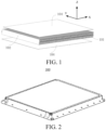
FIG. 1 is a schematic structural diagram showing adhesion of first reinforcing plates to a cell array according to the present disclosure; -
FIG. 2 is a schematic structural diagram of a battery pack according to the present disclosure; -
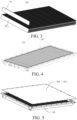
FIG. 3 is a schematic structural diagram of a cell array according to the present disclosure; -
FIG. 4 is a schematic structural diagram of a cell array arranged in a tray according to the present disclosure; -
FIG. 5 is a schematic structural diagram showing adhesion of a cell array to a tray and an upper cover according to the present disclosure; -
FIG. 6 is a schematic structural diagram of a cell array fitted to a side frame of a tray according to the present disclosure; -
FIG. 7 is a partially enlarged viewFIG. 6 ; -
FIG. 8 is a schematic structural diagram of a first supporting structure according to the present disclosure; -
FIG. 9 is a schematic structural diagram of a second supporting structure according to the present disclosure; -
FIG. 10 is an exploded view of a second supporting structure, a cell connector and, and an insulation according to the present disclosure; -
FIG. 11 is a schematic structural diagram showing adhesion of a first reinforcing plate to a bottom plate of a tray according to the present disclosure; -
FIG. 12 is a schematic structural diagram showing arrangement of a protection plate on an outer surface of a bottom plate according to the present disclosure; -
FIG. 13 is a schematic structural diagram showing arrangement of second reinforcing plates in a cell array according to the present disclosure; -
FIG. 14 is a schematic structural diagram of a cell according to the present disclosure; and -
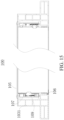
FIG. 15 is a cross-sectional view of a battery pack according to the present disclosure. -
- 100 battery pack;
- 101 cell array; 1011 structural adhesive;
- 102 cell;
- 103 tray; 1031 first side frame; 1032 second side frame; 1033 third side frame; 1034 first support step; 1035 bottom plate;
- 104 first reinforcing plate;
- 105 upper cover;
- 106 first support block;
- 107 second support block; 1071 hole;
- 108 second reinforcing plate;
- 109 insulation partition plate;
- 110 cell connector;
- 111 protection plate;
- X thickness direction of cell;
- Y length direction of cell;
- Z height direction of cell.
- As shown in
FIG. 1 , the present disclosure provides abattery pack 100, including acell array 101 and two first reinforcingplates 104. Thecell array 101 includes a number ofcells 102. Each of the cells is defined with a length L, a thickness D, and a height H between the length L and the thickness D. The number ofcells 102 are arranged along a thickness direction, and thecells 102 are adhered to each other by astructural adhesive 1011. The two first reinforcingplates 104 are arranged opposite to each other and are adhered to the two surfaces of thecell array 101 along an arrangement direction of thecells 102, and are configured to constrain relative positions between thecells 102. - In the related arts, a number of
battery cells 102 are first assembled into a battery module. The number of battery modules are assembled into abattery pack 100 by fasteners or a structural adhesive. The cells and structural members in thebattery pack 100 are relatively scattered, and there are many weak points in gaps between fasteners and cells, gaps between cells, and gaps between fasteners. Once theentire battery pack 100 is squeezed or impacted by an external force, these weak points will be destroyed by the extemal force, and the fastening effects of the fasteners and adhesive fail, resulting in upcoming damages to theentire battery pack 100. - In order to prevent the damage caused by the external force, in the related arts, the strength of the casing of the
battery pack 100 is enhanced for resisting external impact by thebattery pack 100. In order to enhance the strength of thebattery pack 100, abottom plate 1035 of atray 103 is made of steel with higher strength or is made thicker. Or thetray 103 is configured as a multi-layer structure with cavities, and reinforcing ribs are arranged in the cavity structure. However, all the methods of enhancing the strength of thebattery pack 100 lead to an increase in the weight of theentire battery pack 100 or a reduction in the space utilization of thebattery pack 100, reducing the energy density of thebattery pack 100. - In the present disclosure, the
cells 102 are adhered to each other to form acell array 101, and the two first reinforcingplates 104 are adhered to the two opposite surfaces of thecell array 101 along the arrangement direction of thecells 102. The two first reinforcingplates 104 are configured to constrain the relative positions between the number ofcells 102, and form an integral structure with the number ofcells 102. Such an integral structure can eliminate the weak points in the gaps between thecells 102, allowing thebattery pack 100 to be designed as an integral structural member of great rigidity. On the other hand, the two first reinforcingplates 104 and thecell array 101 arranged between the two first reinforcingplates 104 form a honeycomb-like structure. From a mechanical point of view, the honeycomb-like structure can bear the maximum force with the least material. When thecell array 101 is subjected to a load perpendicular to the first reinforcingplate 104, the first reinforcingplate 104 and thecell array 101 deform in coordination. Therefore, the rigidity and strength of thebattery pack 100 are greatly enhanced, thereby improving the mechanical safety and reliability. - In the present disclosure, as shown in
FIG. 14 , thecell 102 is a prismatic cell of a cuboid structure, including two first surfaces opposite to each other in a thickness direction, two second surfaces opposite to each other in a height direction, and two third surfaces opposite to each other in a length direction. The area of the first surface is larger than the area of the second surface, and the area of the first surface is larger than the area of the third surface. - The
cells 102 are arranged along the thickness direction, and thecells 102 are fixedly adhered to each other by a structural adhesive, i.e. the first surfaces of thecells 102 are adhered to each other. In other words, thecells 102 are arranged and adhered with large surfaces thereof facing toward each other, thereby increasing the area of adhesion between thecells 102, and enhancing the adhesion between thecells 102. - In the arrangement direction of the
cells 102, thecells 102 are likely to displace relative to each other. Therefore, by the two first reinforcingplates 104 are adhered to the two opposite surfaces of thecell array 101 along the arrangement direction of thecells 102, the relative positions between thecells 102 can be constrained. - In the present disclosure, the two first reinforcing
plates 104 may be adhered to the two second surfaces of thecells 102, or may be adhered to the two third surfaces of thecells 102. - In the present disclosure, because the length of the
cell 102 is greater than the height of thecell 102 and the height of thecell 102 is greater than the thickness of thecell 102, an area of the second surface defined by the length and the thickness is greater than an area of the third surface defined by the height and the thickness. To enhance the adhesion, the two first reinforcingplates 104 are adhered to the second surfaces of thecells 102. - In the present disclosure, the two surfaces of all the
cells 102 along the arrangement direction may be adhered to the first reinforcingplates 104, or, the two surfaces of only some of thecells 102 along the arrangement direction may be directly adhered to the first reinforcingplates 104. - That is to say, in the present disclosure, the two second surfaces or the two third surfaces of some of the cells may be adhered to the first reinforcing
plates 104, and the two second surfaces or the two third surfaces of some of thecells 102 may not be adhered to the first reinforcingplates 104. - In order to improve the adhesion strength, the number of
cells 102 directly adhered to the two first reinforcingplates 104 is not less than half of the number of cells contained in thecell array 101. - For at least one
cell 102 in thecell array 101, the two second surfaces or the two third surfaces of thecell 102 may both be adhered to the two first reinforcingplates 104; or, one of the two second surfaces or the two third surfaces of thecell 102 is adhered to the first reinforcingplate 104, and the other is not adhered to the first reinforcingplate 104. - In the present disclosure, the two second surfaces or the two third surfaces of the
cell 102 are entirely adhered to the first reinforcingplate 104, or the two second surfaces or the two third surfaces of some of thecells 102 are partially adhered to the first reinforcingplate 104. - In order to enhance the strength of the
entire battery pack 100, in the present disclosure, the two second surfaces or the two third surfaces of all thecells 102 in thecell array 101 are adhered to the two first reinforcingplates 104, to maximize the strength and rigidity of thebattery pack 100. - In the present disclosure, the shapes and areas of the two first reinforcing
plates 104 are not particularly limited, as long as the two first reinforcingplates 104 have a certain strength, can connect thecell array 101 to form a unity, can enhance the structural strength of thecell array 101, and are not readily deformable. - In some embodiments, the shape of the first reinforcing
plate 104 and the shape of the surface of thecell array 101 to which the first reinforcingplate 104 is adhered are the same and are set corresponding to each other, so that the first reinforcingplate 104 can be more easily tightly adhered to the surface of thecell array 101. - In some embodiments, an area of the first reinforcing
plate 104 may be different from an area of the surface of thecell array 101 to which the first reinforcingplate 104 is adhered. When the strength of thebattery pack 100 meets requirements and the first reinforcingplate 104 can connect thecell array 101 to form a unity, the area of the first reinforcingplate 104 may be smaller than the area of the surface of thecell array 101 to which the first reinforcingplate 104 is adhered. - In some implementations, at least one of the first reinforcing
plates 104 is a "¬ "-shaped plate, where the "-"-shaped part of the "¬"-shaped plate is arranged in contact with the second surface of thecell 102 in thecell array 101, and the "|"-shaped part of the "¬"-shaped plate is arranged in contact with the third surface of thecell 102 in thecell array 101; or the "-"-shaped part of the "¬"-shaped plate is arranged in contact with the third surface of thecell 102 in thecell array 101, and the "|"-shaped part of the "¬"-shaped plate is arranged in contact with the second surface of thecell 102 in thecell array 101. - In some implementations, at least one of the first reinforcing
plates 104 is a ""-shaped plate, where the "-"-shaped part of the " "-shaped plate is arranged in contact with the second surface of the
cell 102 in thecell array 101, and the two "|"-shaped parts of the ""-shaped plate are arranged in contact with the third surface of the
cell 102 in thecell array 101; or the "-"-shaped part of the ""-shaped plate is arranged in contact with the third surface of the
cell 102 in thecell array 101, and the two "|"-shaped parts of the ""-shaped plate are arranged in contact with the second surface of the
cell 102 in thecell array 101. - By arranging a bent portion or bent portions bent toward a side surface of the
cell array 101 on an edge of the first reinforcingplate 104, the strength and structural stability of theentire cell array 101 can be enhanced. - In the present disclosure, the first reinforcing
plates 104 and thecells 102 in thecell array 101 constitute a honeycomb-like structure, and the first reinforcingplates 104 and thecells 102 in thecell array 101 deform in coordination. A deformation of the first reinforcingplate 104 causes thecell 102 to deform at the same time, which is equivalent to providing an additional bending moment to the first surface of thecell 102, resulting in a reduced strength of the honeycomb-like structure. As the thickness of the first reinforcingplate 104 increases, the strength of the honeycomb-like structure increases. However, the increase in the strength of the honeycomb-like structure by increasing the thickness of the first reinforcingplate 104 cannot exceed a maximum value. This is because the increase in the thickness of the first reinforcingplate 104 leads to an increase in the bending rigidity of the first reinforcingplate 104, and when the thickness of the first reinforcingplate 104 increases to a certain extent, the strength of the honeycomb-like structure relies on the strength of thecell array 101. Consequently, when an ultimate bearing capacity is reached due to the instability and collapse of the first reinforcingplate 104, the entire honeycomb-like structure loses its bearing capacity. It is found through multiple experiments that when the thickness of the first reinforcingplate 104 is 0.5-5 mm, the first reinforcingplate 104 within this thickness range can provide an optimal reinforcing effect for the honeycomb-like structure, so as to meet the strength requirements of thebattery pack 100. In some implementations, the thickness of the first reinforcingplate 104 is 1-3 mm. - In the present disclosure, the first reinforcing
plates 104 are made of a metal material. - The first reinforcing
plates 104 made of the metal material not only protect thecells 102 inside the battery pack, but also provide a heat dissipation effect. The first reinforcingplates 104 may be made of a metal material with high thermal conductivity, including but not limited to aluminum, copper, and alloys thereof. - In practice, the first reinforcing
plates 104 may be made of an aluminum alloy material, which has a good heat-conducting property and low density. - As shown in
FIG. 1 ,FIG. 6 , andFIG. 14 , the length direction of thecell 102 is defined as a Y direction, the height direction thereof is defined as a Z direction, and the thickness direction is defined as an X direction. - The
cell 102 is substantially of a cuboid structure. To be specific, thecell 102 may be cuboid or cubic, or may be partially special-shaped but basically cuboid or cubic, or may be largely of a cuboid or cubic shape having a notch, a bump, a chamfer, an arc portion, or a bent portion. - In some implementations, the
cell 102 satisfies: 600 mm≤L≤2500 mm, and 10≤L/D≤208. - The
cell 102 has a long length and a small thickness, so thecell 102 can be regarded as a rigid member with great strength, which well functions as a reinforcing beam in the casing and reduces the use of reinforcing ribs in the casing, in this way, not only the weight of thebattery pack 100 can be reduced, but also the structure of the casing can be greatly simplified, thereby improving the utilization of the space inside thebattery pack 100 and the energy density of thebattery pack 100. - According to the invention, in the height direction (i.e., the Z direction) of the
cell 102, a number of layers ofcell arrays 101 are arranged. A partition plate is arranged between two neighboring layers ofcell arrays 101, and the partition plate is fixedly adhered to thecell arrays 101 on two sides of the partition plate. - In this implementation, with the arrangement of the partition plate between the two layers of
cell arrays 101, each layer ofcell array 101 and the partition plates or panels on upper and lower surfaces of thecell array 101 form a number of I-beam structures, to form a honeycomb-like structure. Therefore, the rigidity and strength of thebattery pack 100 are greatly enhanced, thereby improving the mechanical safety and reliability. - In some implementations, As shown in
FIG. 13 , in order to further enhance the overall strength of thebattery pack 100, a second reinforcingplate 108 is arranged between at least two neighboringcells 102. The arrangement of the second reinforcingplate 108 can well absorb the impact received by thecell array 101 in three-dimensional directions, thereby enhancing the mechanical strength of theentire cell array 101. - In the present disclosure, the second reinforcing
plate 108 may be an aluminum or steel plate. The number of the second reinforcingplates 108 is not limited, and may be one or more. When the number of the second reinforcingplates 108 is more than one, the second reinforcingplate 108 may be arranged between every two neighboringcells 102, or the second reinforcingplate 108 may be arranged between only some of the neighboringcells 102. - In order to facilitate the dense arrangement of the
cells 102 in theentire battery pack 100, in some implementations, the second reinforcingplate 108 may be of a shape which is substantially similar to the shape of thecell 102, i.e., may be fabricated into a "dummy cell". The term "dummy cell" means that from the appearance, the dummy cell looks exactly the same as thecell 102, but the dummy cell does not contain an electrode assembly including a positive electrode, a negative electrode, and separator, and provides a reinforcing function only. - The second reinforcing
plate 108 is fixedly adhered to thecells 102 arranged on two sides of the second reinforcingplate 108, to enhance the strength of theentire battery pack 100. - In some implementations, as shown in
FIG. 5 , thebattery pack 100 further includes anupper cover 105 and atray 103. Thetray 103 includes abottom plate 1035 and a side frame surrounding thebottom plate 1035. Theupper cover 105 and thetray 103 are connected to define a cell accommodating chamber, and thecell array 101 is arranged in the cell accommodating chamber. - In some implementations, the two first reinforcing
plates 104 constitute theupper cover 105 and thebottom plate 1035 respectively. - In other words, two surfaces of the
cell array 101 are respectively adhered to theupper cover 105 and thebottom plate 1035. - In this implementation, the surface of the
cell array 101 facing theupper cover 105 is adhered to theupper cover 105, and the surface of thecell array 101 facing thebottom plate 1035 is adhered to thebottom plate 1035. In this way, the two opposite surfaces of thecell array 101 are both adhered to the casing of thebattery pack 100, and thecells 102 are adhered to each other, which improves the integrity of thebattery pack 100, and reduces gaps between fasteners and cells, gaps between cells, and gaps between fasteners. Therefore, weak points in thebattery pack 100 are reduced, thereby improving the strength and rigidity of theentire battery pack 100. - In some implementations, one of the first reinforcing
plates 104 is adhered to an inner surface of the upper cover 105 (not shown in the figure), and the other first reinforcingplate 104 is adhered to an inner surface of the bottom plate 1035 (as shown inFIG. 11 ). In this way, thecell array 101 is indirectly adhered to the casing of thebattery pack 100, which facilitates assembly and processing. - In some implementations, the
upper cover 105 and/or thetray 103 may be of a multi-layer composite structure, to enable thebattery pack 100 to well bear the impact to the entire vehicle, thereby improving the structural strength. - In this implementation, the
bottom plate 1035 of thebattery pack 100 may be designed as a sandwich composite material structure, which can bear the structural strength of the entire battery module. Thebottom plate 1035 is designed as a composite board structure, and integrates a support strength function and a stone-chip resistant function for the bottom of the battery. Thebottom plate 1035 may also integrate a support strength function and a liquid cooling function for the bottom of the battery. - For example, in some implementations, the multi-layer composite structure includes two layers of aluminum plates and a steel plate or a foamed aluminum plate sandwiched between the two layers of aluminum plates, i.e., the multi-layer composite structure is aluminum plate/foamed aluminum plate/aluminum plate or the multi-layer composite structure is aluminum plate/steel plate/aluminum plate.
- In some other implementations, the multi-layer composite structure includes two fiber composite layers and a foamed material layer sandwiched between the two fiber composite layers.
- The foamed material layer includes a foamed polymer material, e.g., a polyurethane foam or phenolic foam material. The foamed material layer has a low thermal conductivity and can provide a good thermal insulation effect. In addition, the foamed material is of low density, and can reduce the weight of the
battery pack 100 as compared with the case where the sealing cover is made of a steel plate or aluminum alloy. - The fiber composite layer includes a glass fiber layer and/or a carbon fiber layer. In other words, the multi-layer composite layer may be glass fiber layer/foamed material layer/glass fiber layer, carbon fiber layer/foamed material layer/carbon fiber layer, or glass fiber layer/foamed material layer/carbon fiber layer. By designing the
upper cover 105 and/or thetray 103 of thebattery pack 100 as a foamed material layer and fiber composite layers distributed on inner and outer sides of the foamed material layer, the fiber layers are of a high tensile strength and elastic modulus, are deformation-resistant when the internal pressure of thebattery pack 100 increases within a certain range, and can also effectively insulate fire and heat, thereby improving the safety performance of thebattery pack 100 under extreme conditions. - The structural strength of the
integral battery pack 100 may provide part of the structural strength of the vehicle. Thebattery pack 100 can be used to enhance the structural strength of the vehicle, such a design allows for the simplification of the structure designed for the frame of the vehicle to protect the structural strength of thebattery pack 100, and meets the requirements for a lightweight design of the vehicle, thereby reducing the manufacturing costs and improving the efficiency of vehicle production. - In some implementations of the present disclosure, as shown in
FIG. 12 , for example, in the implementation where the two first reinforcingplates 104 constitute theupper cover 105 and thebottom plate 1035 respectively, thebottom plate 1035 of thetray 103 is a single-layer aluminum plate, aprotection plate 111 is arranged on an outer surface of thebottom plate 1035 of thetray 103, and theprotection plate 111 is a multi-layer composite structure. Theprotection plate 111 can effectively protect the bottom of thepower battery pack 100 to prevent thepower battery pack 100 from being directly damaged by stone chips or bumping, meets the ball impact requirements on the bottom by a lightweight design, and has good safety and reliability. In addition, the composite material of theprotection plate 111 at the bottom has environmental reliability such as corrosion resistance and aging resistance. The design of thebottom plate 1035 as a detachable compact structure with strong protection facilitates after-sales maintenance in the future, and greatly reduces after-sale maintenance costs. - For the multi-layer composite structure of the
protection plate 111, reference may be made to the above descriptions, so the details will not be repeated herein. - Various connection and fixing methods may be designed for the
protection plate 111 and the side frame of thetray 103 of thebattery pack 100, including riveting, automatic punch riveting, bolted connection, etc., which can be disassembled freely and facilitates repair, maintenance and inspection. - As shown in
FIG. 6 and FIG. 7 , theupper cover 105 is provided with a sealing groove at a position corresponding to the side frame, a sealant layer is arranged in the sealing groove, and theupper cover 105 and thetray 103 are hermetically connected by the sealant. layer. - In some implementation, the sealing groove may be provided on only the
upper cover 105 or on only the side frame, or theupper cover 105 and the side frame are each provided with the sealing groove. - In some implementation, the
upper cover 105 may also be hermetically fixed to the side frame by riveting or bolts, so as to improve the sealing performance and the structural strength of theentire battery pack 100. - At the position for sealed fitting between the side frame of the battery and the
upper cover 105, a sealing groove is designed for sealing. The sealing groove may be designed on the side frame of the battery or on theupper cover 105, to ensure the sealing and fixing between the side frame and theupper cover 105. - A structural adhesive is filled between the
cell array 101 and an inner surface of the side frame. A gap between thecell array 101 and the side frame often becomes a weak point, and by injecting the structural adhesive to adhere thecell 102 to the side frame, the strength is enhanced. - As shown in
FIG. 6 and FIG. 7 , in some embodiments, each of thecells 102 is substantially of a cuboid structure, including a first end and a second end arranged opposite to each other along the length direction. The side frame includes afirst side frame 1031 and asecond side frame 1032 arranged opposite to each other along the length direction of each of thecells 102. Thecells 102 are disposed between thefirst side frame 1031 and thesecond side frame 1032. The first end of each of thecells 102 is supported by thefirst side frame 1031, and the second end of each of thecells 102 is supported by thesecond side frame 1032. In other words, thecells 102 extend between thefirst side frame 1031 and thesecond side frame 1032. - Because the
cells 102 extend between thefirst side frame 1031 and thesecond side frame 1032, and the two ends of thecell 102 are respectively supported by thefirst side frame 1031 and thesecond side frame 1032, thecell 102 itself can serve as a transverse beam or longitudinal beam to enhance the structural strength of the casing. That is to say, no reinforcing structure for enhancing the structural strength needs to be arranged in the casing, that is, thecell 102 itself can be directly used to replace the reinforcing structure to ensure the structural strength of the casing, thereby ensuring that the casing does not easily deform under an external force. - In some embodiments of the present disclosure, a
first support step 1034 is arranged on thefirst side frame 1031, a second support step is arranged on thesecond side frame 1032, the first end of each of thecells 102 is supported by thefirst support step 1034, and the second end of each of thecells 102 is supported by the second support step. - In some embodiments of the present disclosure, the first end of each of the
cells 102 may be directly or indirectly supported by thefirst side frame 1031, and the second end of each of thecells 102 may be directly or indirectly supported by thesecond side frame 1032. The term "directly" means that the first end of thecell 102 is in direct contact fit with and supported by thefirst side frame 1031, and the second end of each of thecells 102 is in direct contact fit with and supported by thesecond side frame 1032. - As shown in
FIG. 6 and FIG. 7 , thebattery pack 100 further includes a supporting structure. The first end of each of thecells 102 is fitted to and supported by thefirst side frame 1031 through the supporting structure, and the second end of thecell 102 is fitted to and supported by thesecond side frame 1032 through the supporting structure. - In this implementation, the term "fit" means that a spacing between the two side frames is configured for mounting one
cell 102. The fit may be various fitting methods such as clearance fit, interference fit, tight fit, immovable fit, etc., thereby achieving the objective of the present disclosure. - The arrangement of the supporting structure between the two ends of the
cell 102 in the length direction and the side frame can enhance the strength of thecell array 101 and the strength of the battery frame. - With the arrangement of the supporting structure, when the side frame receives an external force, the
cell 102 itself is a rigid member with great strength, and can transmit a force to the side frame through the supporting structure, to prevent plastic deformation of the side frame. - In some implementations, as shown in
FIG. 6, FIG. 7 , andFIG. 15 , the supporting structure includes afirst support block 106, a lower surface of the first end of each of thecells 102 is supported by thefirst side frame 1031 through thefirst support block 106, and/ or a lower surface of the second end of thecell 102 is supported by thesecond side frame 1032 through thefirst support block 106. - The
first support block 106 is fixedly mounted on lower surfaces of the ends of thecell 102 in the length direction, which on the one hand facilitates the positioning of thecells 102 when the cells are arranged to form thecell array 101, and on the other hand insulates and isolates thecells 102 from thebottom plate 1035 of thetray 103. In addition, the side frame can be connected to a lower end surface of thecell 102 by thefirst support block 106, thereby improving the strength and rigidity of theentire battery pack 100. - Through the
first support block 106, the lower surface of the first end of each of thecells 102 may be supported by thefirst side frame 1031, or may be supported by the support step on thefirst side frame 1031. Through thefirst support block 106, the lower surface of the second end of thecell 102 may be supported by thesecond side frame 1032 through thefirst support block 106, or may be supported by the support step on thesecond side frame 1032. - In some implementations of the present disclosure, the supporting structure includes a
second support block 107, the first end of each of thecells 102 facing thefirst side frame 1031 is fitted to thefirst side frame 1031 through thesecond support block 107, and/or, the second end of each of thecells 102 facing thesecond side frame 1032 is fitted to thesecond side frame 1032 through thesecond support block 107. - Each of the
cells 102 includes electrode terminals. The electrode terminals are respectively arranged at the first end and the second end of each of thecells 102.Holes 1071 are provided on the supporting structure. The electrode terminals of each of thecells 102 extend through theholes 1071 respectively and are electrically connected by acell connector 110. - In a first implementation of the present disclosure, as shown in
FIG. 10 andFIG. 14 , thebattery pack 100 further includes aninsulation partition plate 109, and theinsulation partition plate 109 is arranged between the supporting structure and an inner surface of the side frame. The insulating partition plate is configured to insulate thecell connector 110 and the electrode terminals from the side frame, to prevent a short circuit and other safety problems. - As shown in
FIG. 7 andFIG. 15 , a second supporting structure is mounted on a side surface of the electrode terminals, to fix thecell connector 110 of each of thecells 102 and a flexible printed circuit board (FPC). - The electrode terminals of each of the
cells 102 are also weak points, and thesecond support block 107 can protect the electrode terminals. - In the present disclosure, the specific structure of the supporting structure is not limited, as long as the supporting structure is of a certain strength and is resistant to deformation under an external force. In some implementations, the material of the supporting structure includes one or more of polyether plastic (PPS), glass fiber, or polycarbonate.
- In some embodiments of the present disclosure, the side frame includes a
third side frame 1033 and a fourth side frame arranged opposite to each other along the arrangement direction of thecells 102. The number ofcells 102 are arranged side by side between thethird side frame 1033 and the fourth side frame. Thethird side frame 1033 and the fourth side frame are respectively fixedly adhered to each of thecells 102 adjacent thereto. - The arrangement of the
third side frame 1033 and the fourth side frame makes thecell array 101 and the side frame to form a unity, and the side frame of the battery tightly clamps thecell array 101 along the arrangement direction of thecells 102. - That is to say, the
third side frame 1033 applies an acting force, which is toward the fourth side frame, on thecell 102 arranged adjacent to thethird side frame 1033, and the fourth side frame applies an acting force, which is toward thethird side frame 1033, on thecell 102 arranged adjacent to the fourth side frame, so that the number ofcells 102 can be closely arranged between thethird side frame 1033 and the fourth side frame, and the number ofcells 102 can closely fit each other. Moreover, thethird side frame 1033 and the fourth side frame may provide a limiting function for thecells 102, and especially when thecell 102 undergoes slight expansion, may provide a buffering function and an inward pressure for thecell 102, to prevent thecell 102 from excessive expansion and deformation. - In order to further solve the expansion problem of the
cell array 101, a reinforcing beam is arranged on thethird side frame 1033 and/or the fourth side frame. The reinforcing beam may be in close contact with to the outer surface of each of the cells adjacent thereto or may be spaced from each of the cells adjacent thereto by a gap, to provide a limiting function for the expansion of thecell array 101. - The side frame and the
bottom plate 1035 of thetray 103 may be adhered to each other by a structural adhesive, may be directly welded together, or may be connected by bolts. The side frame may be an integral frame or a split-type frame. In some embodiments of the present disclosure, the side frame is a split-type frame, i.e. thefirst side frame 1031, thesecond side frame 1032, thethird side frame 1033, and the fourth side frame are separate from each other. The connection between the two side frames may be further reinforced by a fastener. - An assembly process of the
battery pack 100 is described below using an example where each of thecells 102 is a cuboid cell, the electrode terminals of each of thecells 102 are arranged on the two ends of thecell 102 along the length direction, thefirst side frame 1031, thesecond side frame 1032, thethird side frame 1033, and the fourth side frame are separate from each other, and the two first reinforcingplates 104 constitute theupper cover 105 and thebottom plate 1035 of the battery pack respectively. - Step 1: The number of
cells 102 are arranged along the thickness direction to form the cell array, with thecells 102 being aligned to each other in the height direction and the length direction. Thecells 102 are adhered to each other by astructural adhesive 1011. The arrangement direction of thecells 102 is defined as an X direction. The length direction of thecell 102 is defined as a Y direction. - Step 2: Along the X direction, two opposite first surfaces with the largest areas of the two
outermost cells 102 in thecell array 101 are respectively adhered to thethird side frame 1033 and the fourth side frame (where this direction is not a lead-out direction of the electrode terminals). - Step 3: Along the Y direction, the
first side frame 1031 and thesecond side frame 1032 are arranged on the two end faces of thecell array 101. - Step 4: The
first side frame 1031 and thesecond side frame 1032 are connected to thethird side frame 1033 and the fourth side frame by welding or fasteners (bolts, etc.). - Step 4: The two first reinforcing
plates 104 are adhered to the two opposite surfaces of thecell array 101 along the arrangement direction of thecells 102. - Step 5: The first reinforcing
plates 104 are connected to thefirst side frame 1031, thesecond side frame 1032, thethird side frame 1033, and the fourth side frame by a structural adhesive or fasteners. One of the first reinforcingplates 104 is theupper cover 105 of thebattery pack 100. The other first reinforcingplate 104 is thebottom plate 1035 of thebattery pack 100. - Step 6: The
protection plate 111 is further arranged on the outer surface of thebottom plate 1035. - Step 7: A structural adhesive is filled in or a supporting structure is arranged at the gap between the
cell array 101 and the side frame. - As can be seen from the above assembly process, the six surfaces of the
cell 102 are all of a strong structural strength, and the design of thebattery pack 100 as an integral structure greatly enhances the rigidity and strength, thereby greatly improving the mechanical safety and reliability. The structural strength of theintegral battery pack 100 may provide part of the structural strength of the vehicle. Thebattery pack 100 can be used to enhance the structural strength of the vehicle, such a design allows for the simplification of the structure designed for the frame of the vehicle to protect the structural strength of thebattery pack 100, and meets the requirements for a lightweight design of the vehicle, thereby reducing the manufacturing costs and improving the efficiency of vehicle production. - In the present disclosure, the
battery pack 100 further includes a battery management system. - According to a second aspect of the present disclosure, an electric vehicle is provided, including the
above battery pack 100. The electric vehicle has a long battery life and requires low costs. - In the description of the present disclosure, it should be noted that unless otherwise explicitly specified or defined, the terms such as "mount", "install", "connect", and "connection" should be understood in a broad sense. For example, the connection may be a fixed connection, a detachable connection, or an integral connection; or the connection may be a mechanical connection or an electrical connection; or the connection may be a direct connection, an indirect connection through an intermediary, or internal communication between two components. A person of ordinary skill in the art may understand the specific meanings of the foregoing terms in the present disclosure according to specific situations.
- In description of this specification, description of reference terms such as "an embodiment", "specific embodiments", or "an example", means including specific features, structures, materials, or features described in the embodiment or example in at least one embodiment or example of the present disclosure. In this specification, schematic descriptions of the foregoing terms do not necessarily point at a same embodiment or example. In addition, the described specific features, structures, materials, or characteristics may be combined in a proper manner in any one or more of the embodiments or examples.
- Although the embodiments of the present disclosure have been shown and described, a person of ordinary skill in the art is to be understand that various changes, modifications, replacements, and variations may be made to the embodiments without departing from the present The herein claimed invention is defined by the appended claims.
Claims (16)
- A battery pack (100), comprising:a cell array (101), wherein the cell array comprises a plurality of cells (102); each of the cells is defined with a length L, a thickness D, and a height H between the length L and the thickness D,the plurality of cells (102) are arranged along a thickness direction, and the cells are adhered to each other by a structural adhesive (1011);two first reinforcing plates (104); wherein the two first reinforcing plates are arranged opposite to each other and are respectively adhered to two surfaces of the cell array (101) along an arrangement direction of the cells (102), and are configured to constrain relative positions between the cells;characterized in that the battery pack comprises a plurality of layers of cell arrays (101) arranged along a height direction (Z) of the cells, a partition plate is arranged between two neighboring layers of cell arrays, and the partition plate is fixedly adhered to the cell arrays on two sides of the partition plate.
- The battery pack according to claim 1, wherein the two first reinforcing plates (104) are respectively adhered to two opposite surfaces of the cells (102) along a height direction (Z).
- The battery pack according to claim 1 or 2, wherein at least one of the cells (102) satisfies:

- The battery pack according to any one of claims 1-3, wherein a second reinforcing plate (108) is arranged between at least two neighboring cells; and the second reinforcing plate (108) is fixedly adhered to the cells (102) arranged on two sides of the second reinforcing plate.
- The battery pack according to any one of claims 1-4, wherein the battery pack further comprises an upper cover (105) and a tray (103), the tray comprises a bottom plate (1035) and a side frame surrounding the bottom plate, the upper cover and the tray are connected to define a cell accommodating chamber, and the cell array is arranged in the cell accommodating chamber.
- The battery pack according to claim 5, wherein the two first reinforcing plates (104) constitute the upper cover (105) and the bottom plate (1035) respectively.
- The battery pack according to claim 6, wherein the battery pack further comprises a protection plate (111), and the protection plate is arranged on an outer surface of the bottom plate (1035);wherein preferably the protection plate (111) comprises two layers of aluminum plates and a steel plate or a foamed aluminum plate sandwiched between the two layers of aluminum plates;or wherein preferably the protection plate (111) comprises two fiber composite layers and a foamed polymer layer sandwiched between the two fiber composite layers, and the fiber composite layer comprises a glass fiber layer or a carbon fiber layer.
- The battery pack according to claims 5, wherein outer surfaces of the two first reinforcing plates (104) are respectively adhered to an inner surface of the upper cover (105) and an inner surface of the bottom plate (1035).
- The battery pack according to any one of claims 6-8, wherein at least one of the bottom plate (1035) or the upper cover (105) comprises two layers of aluminum plates and a steel plate or a foamed aluminum plate sandwiched between the two layers of aluminum plates;
or at least one of the bottom plate (1035) and the upper cover (105) comprises two fiber composite layers and a foamed polymer layer sandwiched between the two fiber composite layers, and the fiber composite layer comprises a glass fiber layer or a carbon fiber layer. - The battery pack according to any one of claims 6-9, wherein the upper cover (105) is provided with a sealing groove at a position corresponding to the side frame, a sealant layer is arranged in the sealing groove, and the upper cover and the tray are hermetically connected by the sealant layer.
- The battery pack according to any one of claims 6-10, wherein each of the cells (102) comprises a first end and a second end arranged opposite to each other along a length direction (Y), the side frame comprises a first side frame (1031) and a second side frame (1032) arranged opposite to each other along the length direction (Y) of each of the cells, the first end of each of the cells is supported by the first side frame (1031), and the second end of each of the cells is supported by the second side frame (1032).
- The battery pack according to claim 11, wherein a first support step (1034) is arranged on the first side frame (1031), a second support step is arranged on the second side frame, the first end of each of the cells is supported by the first support step, and the second end of each of the cells is supported by the second support step.
- The battery pack according to claim 12, wherein the battery pack further comprises a supporting structure, the first end of each of the cells is fitted to and supported by the first side frame (1031) through the supporting structure, and/or the second end of the cell is fitted to and supported by the second side frame (1032) through the supporting structure.
- The battery pack according to claim 13, wherein each of the cells comprises electrode terminals, the electrode terminals are respectively arranged at the first end and the second end of each of the cells, holes are provided on the supporting structure, and the electrode terminals of each of the cells extend through the holes respectively and are electrically connected by a cell connector.
- The battery pack according to claim 14, wherein the battery pack further comprises an insulation partition plate (109), and the insulation partition plate is arranged between the supporting structure and an inner surface of the side frame.
- An electric vehicle, comprising the battery pack (100) according to any one of claims 1-15.
Applications Claiming Priority (2)
| Application Number | Priority Date | Filing Date | Title |
|---|---|---|---|
| CN201911198132.9A CN112874285A (en) | 2019-11-29 | 2019-11-29 | Battery pack and electric vehicle |
| PCT/CN2020/122882 WO2021103867A1 (en) | 2019-11-29 | 2020-10-22 | Battery pack and electric vehicle |
Publications (3)
| Publication Number | Publication Date |
|---|---|
| EP4056408A1 EP4056408A1 (en) | 2022-09-14 |
| EP4056408A4 EP4056408A4 (en) | 2023-01-11 |
| EP4056408B1 true EP4056408B1 (en) | 2025-04-09 |
Family
ID=76038325
Family Applications (1)
| Application Number | Title | Priority Date | Filing Date |
|---|---|---|---|
| EP20893130.3A Active EP4056408B1 (en) | 2019-11-29 | 2020-10-22 | Battery pack and electric vehicle |
Country Status (9)
| Country | Link |
|---|---|
| US (1) | US20230023909A1 (en) |
| EP (1) | EP4056408B1 (en) |
| JP (2) | JP7644115B2 (en) |
| KR (1) | KR102839737B1 (en) |
| CN (3) | CN117799413A (en) |
| ES (1) | ES3023939T3 (en) |
| HU (1) | HUE071217T2 (en) |
| PL (1) | PL4056408T3 (en) |
| WO (1) | WO2021103867A1 (en) |
Families Citing this family (13)
| Publication number | Priority date | Publication date | Assignee | Title |
|---|---|---|---|---|
| US11996576B2 (en) * | 2020-07-03 | 2024-05-28 | Teijin Automotive Technologies, Inc. | Impact resistant frame of battery containment system |
| DE102021114483A1 (en) * | 2021-06-07 | 2022-12-08 | Audi Aktiengesellschaft | Method of connecting two components and battery module |
| DE102021115668A1 (en) * | 2021-06-17 | 2022-12-22 | Dr. Ing. H.C. F. Porsche Aktiengesellschaft | Battery arrangement for an electric vehicle |
| CN115692974B (en) * | 2021-07-30 | 2025-02-11 | 比亚迪股份有限公司 | Battery pack and vehicle |
| CN217158406U (en) * | 2022-01-12 | 2022-08-09 | 宁德时代新能源科技股份有限公司 | Battery package and electric device |
| CN216980743U (en) * | 2022-01-28 | 2022-07-15 | 比亚迪股份有限公司 | A guard plate, battery package and vehicle for battery package |
| JP7376856B1 (en) * | 2022-06-17 | 2023-11-09 | Jfeスチール株式会社 | battery case |
| CN115411425A (en) * | 2022-09-23 | 2022-11-29 | 广州小鹏汽车科技有限公司 | Battery pack and vehicle |
| CN115863895B (en) * | 2022-12-23 | 2026-01-30 | 浙江极氪智能科技有限公司 | Battery packs and vehicles |
| JP7719113B2 (en) * | 2023-03-07 | 2025-08-05 | プライムプラネットエナジー&ソリューションズ株式会社 | Battery pack and manufacturing method thereof |
| CN116526045A (en) * | 2023-05-26 | 2023-08-01 | 一汽解放汽车有限公司 | Battery pack box and preparation method |
| CN118231905A (en) * | 2023-09-25 | 2024-06-21 | 比亚迪股份有限公司 | Battery pack and electricity utilization device |
| KR102628969B1 (en) * | 2023-09-27 | 2024-01-24 | 주식회사케이에스엠 | Electric vehicle battery case manufacturing method |
Citations (1)
| Publication number | Priority date | Publication date | Assignee | Title |
|---|---|---|---|---|
| JP2016066624A (en) * | 2015-12-22 | 2016-04-28 | 三洋電機株式会社 | Power unit |
Family Cites Families (24)
| Publication number | Priority date | Publication date | Assignee | Title |
|---|---|---|---|---|
| JP4747539B2 (en) * | 2004-09-13 | 2011-08-17 | マックス株式会社 | Battery pack |
| JP2009295381A (en) * | 2008-06-04 | 2009-12-17 | Toshiba Corp | Battery cell and battery pack |
| JP2012043758A (en) * | 2010-08-23 | 2012-03-01 | Toshiba Corp | Battery pack device |
| DE102011076575A1 (en) * | 2011-05-27 | 2012-11-29 | Bmw Ag | Energy storage module of several, in particular prismatic memory cells and method for producing an energy storage module and method for producing an end plate for an energy storage module |
| JP6010326B2 (en) * | 2011-06-02 | 2016-10-19 | 株式会社東芝 | Secondary battery device and method for manufacturing secondary battery device |
| JP5868676B2 (en) * | 2011-11-30 | 2016-02-24 | 三洋電機株式会社 | Power supply device, vehicle including the same, and power storage device |
| JP6148555B2 (en) * | 2013-07-16 | 2017-06-14 | 株式会社ジーエスエレテック | Busbar module device |
| US9831482B2 (en) * | 2013-09-06 | 2017-11-28 | Johnson Controls Technology Company | Battery module lid system and method |
| CN107078243B (en) * | 2014-06-20 | 2020-04-24 | 罗伯特·博世有限公司 | Battery module with cell fixation |
| US9911951B2 (en) * | 2014-09-30 | 2018-03-06 | Johnson Controls Technology Company | Battery module compressed cell assembly |
| KR101941117B1 (en) * | 2015-02-27 | 2019-01-23 | 주식회사 엘지화학 | Battery module |
| DE102015108611A1 (en) * | 2015-06-01 | 2016-12-01 | Dr. Ing. H.C. F. Porsche Aktiengesellschaft | vehicle component |
| WO2017056742A1 (en) * | 2015-09-29 | 2017-04-06 | 株式会社Gsユアサ | Electricity storage device and method for manufacturing electricity storage device |
| WO2017163359A1 (en) * | 2016-03-24 | 2017-09-28 | 株式会社 東芝 | Secondary battery device |
| JP7020804B2 (en) * | 2017-06-19 | 2022-02-16 | 本田技研工業株式会社 | Battery pack |
| WO2019001357A1 (en) * | 2017-06-30 | 2019-01-03 | 比亚迪股份有限公司 | Battery tray, battery pack assembly, and vehicle having same |
| US11394086B2 (en) * | 2017-09-27 | 2022-07-19 | Kabushiki Kaisha Toshiba | Battery module and connection member |
| CN107994149A (en) * | 2017-11-17 | 2018-05-04 | 康得复合材料有限责任公司 | Mixed structure battery pack |
| CN108321314A (en) * | 2018-01-18 | 2018-07-24 | 湖南三迅新能源科技有限公司 | Lightweight power battery pack |
| CN208797084U (en) * | 2018-11-19 | 2019-04-26 | 浙江爱特新能源汽车有限公司 | A kind of power battery pack |
| CN209169330U (en) * | 2018-11-26 | 2019-07-26 | 天津普兰能源科技有限公司 | A kind of electrokinetic cell system plate structure of cooling |
| CN111384334B (en) * | 2018-12-30 | 2024-09-13 | 宁德时代新能源科技股份有限公司 | Battery pack |
| US12230820B2 (en) * | 2019-01-09 | 2025-02-18 | Byd Company Limited | Power battery pack and electric vehicle |
| CN209561492U (en) * | 2019-03-28 | 2019-10-29 | 宁德时代新能源科技股份有限公司 | Battery modules and battery packs |
-
2019
- 2019-11-29 CN CN202311408541.3A patent/CN117799413A/en active Pending
- 2019-11-29 CN CN202311406256.8A patent/CN117533110A/en active Pending
- 2019-11-29 CN CN201911198132.9A patent/CN112874285A/en active Pending
-
2020
- 2020-10-22 HU HUE20893130A patent/HUE071217T2/en unknown
- 2020-10-22 JP JP2022531447A patent/JP7644115B2/en active Active
- 2020-10-22 KR KR1020227017471A patent/KR102839737B1/en active Active
- 2020-10-22 WO PCT/CN2020/122882 patent/WO2021103867A1/en not_active Ceased
- 2020-10-22 EP EP20893130.3A patent/EP4056408B1/en active Active
- 2020-10-22 US US17/780,892 patent/US20230023909A1/en active Pending
- 2020-10-22 ES ES20893130T patent/ES3023939T3/en active Active
- 2020-10-22 PL PL20893130.3T patent/PL4056408T3/en unknown
-
2024
- 2024-04-05 JP JP2024061252A patent/JP2024095749A/en active Pending
Patent Citations (1)
| Publication number | Priority date | Publication date | Assignee | Title |
|---|---|---|---|---|
| JP2016066624A (en) * | 2015-12-22 | 2016-04-28 | 三洋電機株式会社 | Power unit |
Also Published As
| Publication number | Publication date |
|---|---|
| US20230023909A1 (en) | 2023-01-26 |
| HUE071217T2 (en) | 2025-08-28 |
| JP2024095749A (en) | 2024-07-10 |
| JP7644115B2 (en) | 2025-03-11 |
| EP4056408A1 (en) | 2022-09-14 |
| EP4056408A4 (en) | 2023-01-11 |
| JP2023503506A (en) | 2023-01-30 |
| CN117799413A (en) | 2024-04-02 |
| CN117533110A (en) | 2024-02-09 |
| KR20220087529A (en) | 2022-06-24 |
| CN112874285A (en) | 2021-06-01 |
| PL4056408T3 (en) | 2025-08-04 |
| WO2021103867A1 (en) | 2021-06-03 |
| ES3023939T3 (en) | 2025-06-03 |
| KR102839737B1 (en) | 2025-07-30 |
Similar Documents
| Publication | Publication Date | Title |
|---|---|---|
| EP4056408B1 (en) | Battery pack and electric vehicle | |
| JP7577119B2 (en) | Battery packs and electric vehicles | |
| KR102953580B1 (en) | Large battery module and a bettery pack including the same | |
| CN110993845B (en) | Battery pack and electric vehicle | |
| EP2624330B1 (en) | Battery Pack | |
| KR101150247B1 (en) | Battery module having flexibility in designing structure of module and battery pack employed with the same | |
| US12034137B2 (en) | Mounting bracket for cell supervision circuit, battery pack, and vehicle | |
| KR20200112246A (en) | A battery module having a module housing of a thin plate type and a battery pack including the same | |
| CN115863890B (en) | A soft-pack battery module | |
| CN224096889U (en) | Battery box body and battery box | |
| CN115377597A (en) | Frameless battery pack and method of manufacturing the same | |
| CN224036524U (en) | A housing for an energy storage device and the energy storage device itself. | |
| CN116097510B (en) | Battery pack, vehicle including the battery pack, and energy storage system | |
| CN223451090U (en) | Battery packs and electrical equipment | |
| US20260038934A1 (en) | Cell module, battery pack and method for assembling battery pack, vehicle | |
| EP4675785A1 (en) | Battery housing with external frame | |
| CN118281456A (en) | Battery pack and electricity utilization device | |
| CN121769393A (en) | Battery packs and electrical equipment | |
| KR20250138128A (en) | Power storage device and vehicle | |
| CN120237353A (en) | Battery packs and electrical equipment | |
| KR20250011444A (en) | Battery pack and device including the same | |
| CN121367000A (en) | Battery box and battery pack | |
| CN117397100A (en) | Lightweight battery module housing with improved stiffness and battery pack including same | |
| CN121192349A (en) | Battery box and battery pack | |
| CN115275481A (en) | Battery system |
Legal Events
| Date | Code | Title | Description |
|---|---|---|---|
| STAA | Information on the status of an ep patent application or granted ep patent |
Free format text: STATUS: THE INTERNATIONAL PUBLICATION HAS BEEN MADE |
|
| PUAI | Public reference made under article 153(3) epc to a published international application that has entered the european phase |
Free format text: ORIGINAL CODE: 0009012 |
|
| STAA | Information on the status of an ep patent application or granted ep patent |
Free format text: STATUS: REQUEST FOR EXAMINATION WAS MADE |
|
| 17P | Request for examination filed |
Effective date: 20220609 |
|
| AK | Designated contracting states |
Kind code of ref document: A1 Designated state(s): AL AT BE BG CH CY CZ DE DK EE ES FI FR GB GR HR HU IE IS IT LI LT LU LV MC MK MT NL NO PL PT RO RS SE SI SK SM TR |
|
| A4 | Supplementary search report drawn up and despatched |
Effective date: 20221212 |
|
| RIC1 | Information provided on ipc code assigned before grant |
Ipc: B60K 1/04 20190101ALI20221206BHEP Ipc: H01M 10/625 20140101ALI20221206BHEP Ipc: B60L 50/64 20190101AFI20221206BHEP |
|
| DAV | Request for validation of the european patent (deleted) | ||
| DAX | Request for extension of the european patent (deleted) | ||
| GRAP | Despatch of communication of intention to grant a patent |
Free format text: ORIGINAL CODE: EPIDOSNIGR1 |
|
| STAA | Information on the status of an ep patent application or granted ep patent |
Free format text: STATUS: GRANT OF PATENT IS INTENDED |
|
| INTG | Intention to grant announced |
Effective date: 20241119 |
|
| GRAS | Grant fee paid |
Free format text: ORIGINAL CODE: EPIDOSNIGR3 |
|
| GRAA | (expected) grant |
Free format text: ORIGINAL CODE: 0009210 |
|
| STAA | Information on the status of an ep patent application or granted ep patent |
Free format text: STATUS: THE PATENT HAS BEEN GRANTED |
|
| AK | Designated contracting states |
Kind code of ref document: B1 Designated state(s): AL AT BE BG CH CY CZ DE DK EE ES FI FR GB GR HR HU IE IS IT LI LT LU LV MC MK MT NL NO PL PT RO RS SE SI SK SM TR |
|
| REG | Reference to a national code |
Ref country code: GB Ref legal event code: FG4D |
|
| REG | Reference to a national code |
Ref country code: CH Ref legal event code: EP |
|
| REG | Reference to a national code |
Ref country code: DE Ref legal event code: R096 Ref document number: 602020049322 Country of ref document: DE |
|
| REG | Reference to a national code |
Ref country code: IE Ref legal event code: FG4D |
|
| P01 | Opt-out of the competence of the unified patent court (upc) registered |
Free format text: CASE NUMBER: APP_17378/2025 Effective date: 20250409 |
|
| REG | Reference to a national code |
Ref country code: NL Ref legal event code: FP |
|
| REG | Reference to a national code |
Ref country code: ES Ref legal event code: FG2A Ref document number: 3023939 Country of ref document: ES Kind code of ref document: T3 Effective date: 20250603 |
|
| REG | Reference to a national code |
Ref country code: HU Ref legal event code: AG4A Ref document number: E071217 Country of ref document: HU |
|
| REG | Reference to a national code |
Ref country code: AT Ref legal event code: MK05 Ref document number: 1783258 Country of ref document: AT Kind code of ref document: T Effective date: 20250409 |
|
| PG25 | Lapsed in a contracting state [announced via postgrant information from national office to epo] |
Ref country code: FI Free format text: LAPSE BECAUSE OF FAILURE TO SUBMIT A TRANSLATION OF THE DESCRIPTION OR TO PAY THE FEE WITHIN THE PRESCRIBED TIME-LIMIT Effective date: 20250409 Ref country code: PT Free format text: LAPSE BECAUSE OF FAILURE TO SUBMIT A TRANSLATION OF THE DESCRIPTION OR TO PAY THE FEE WITHIN THE PRESCRIBED TIME-LIMIT Effective date: 20250811 |
|
| REG | Reference to a national code |
Ref country code: LT Ref legal event code: MG9D |
|
| PG25 | Lapsed in a contracting state [announced via postgrant information from national office to epo] |
Ref country code: GR Free format text: LAPSE BECAUSE OF FAILURE TO SUBMIT A TRANSLATION OF THE DESCRIPTION OR TO PAY THE FEE WITHIN THE PRESCRIBED TIME-LIMIT Effective date: 20250710 |
|
| PG25 | Lapsed in a contracting state [announced via postgrant information from national office to epo] |
Ref country code: BG Free format text: LAPSE BECAUSE OF FAILURE TO SUBMIT A TRANSLATION OF THE DESCRIPTION OR TO PAY THE FEE WITHIN THE PRESCRIBED TIME-LIMIT Effective date: 20250409 |
|
| PG25 | Lapsed in a contracting state [announced via postgrant information from national office to epo] |
Ref country code: HR Free format text: LAPSE BECAUSE OF FAILURE TO SUBMIT A TRANSLATION OF THE DESCRIPTION OR TO PAY THE FEE WITHIN THE PRESCRIBED TIME-LIMIT Effective date: 20250409 |
|
| PG25 | Lapsed in a contracting state [announced via postgrant information from national office to epo] |
Ref country code: AT Free format text: LAPSE BECAUSE OF FAILURE TO SUBMIT A TRANSLATION OF THE DESCRIPTION OR TO PAY THE FEE WITHIN THE PRESCRIBED TIME-LIMIT Effective date: 20250409 |
|
| PG25 | Lapsed in a contracting state [announced via postgrant information from national office to epo] |
Ref country code: RS Free format text: LAPSE BECAUSE OF FAILURE TO SUBMIT A TRANSLATION OF THE DESCRIPTION OR TO PAY THE FEE WITHIN THE PRESCRIBED TIME-LIMIT Effective date: 20250709 |
|
| PG25 | Lapsed in a contracting state [announced via postgrant information from national office to epo] |
Ref country code: IS Free format text: LAPSE BECAUSE OF FAILURE TO SUBMIT A TRANSLATION OF THE DESCRIPTION OR TO PAY THE FEE WITHIN THE PRESCRIBED TIME-LIMIT Effective date: 20250809 |
|
| PG25 | Lapsed in a contracting state [announced via postgrant information from national office to epo] |
Ref country code: LV Free format text: LAPSE BECAUSE OF FAILURE TO SUBMIT A TRANSLATION OF THE DESCRIPTION OR TO PAY THE FEE WITHIN THE PRESCRIBED TIME-LIMIT Effective date: 20250409 |
|
| PGFP | Annual fee paid to national office [announced via postgrant information from national office to epo] |
Ref country code: HU Payment date: 20251027 Year of fee payment: 6 |
|
| PGFP | Annual fee paid to national office [announced via postgrant information from national office to epo] |
Ref country code: NL Payment date: 20251021 Year of fee payment: 6 |
|
| PGFP | Annual fee paid to national office [announced via postgrant information from national office to epo] |
Ref country code: DE Payment date: 20251021 Year of fee payment: 6 |
|
| PGFP | Annual fee paid to national office [announced via postgrant information from national office to epo] |
Ref country code: GB Payment date: 20251022 Year of fee payment: 6 |
|
| PGFP | Annual fee paid to national office [announced via postgrant information from national office to epo] |
Ref country code: NO Payment date: 20251024 Year of fee payment: 6 |
|
| REG | Reference to a national code |
Ref country code: DE Ref legal event code: R097 Ref document number: 602020049322 Country of ref document: DE |
|
| PG25 | Lapsed in a contracting state [announced via postgrant information from national office to epo] |
Ref country code: DK Free format text: LAPSE BECAUSE OF FAILURE TO SUBMIT A TRANSLATION OF THE DESCRIPTION OR TO PAY THE FEE WITHIN THE PRESCRIBED TIME-LIMIT Effective date: 20250409 Ref country code: SM Free format text: LAPSE BECAUSE OF FAILURE TO SUBMIT A TRANSLATION OF THE DESCRIPTION OR TO PAY THE FEE WITHIN THE PRESCRIBED TIME-LIMIT Effective date: 20250409 |
|
| PGFP | Annual fee paid to national office [announced via postgrant information from national office to epo] |
Ref country code: IT Payment date: 20251024 Year of fee payment: 6 |
|
| PGFP | Annual fee paid to national office [announced via postgrant information from national office to epo] |
Ref country code: FR Payment date: 20251030 Year of fee payment: 6 |
|
| PG25 | Lapsed in a contracting state [announced via postgrant information from national office to epo] |
Ref country code: CZ Free format text: LAPSE BECAUSE OF FAILURE TO SUBMIT A TRANSLATION OF THE DESCRIPTION OR TO PAY THE FEE WITHIN THE PRESCRIBED TIME-LIMIT Effective date: 20250409 |
|
| PGFP | Annual fee paid to national office [announced via postgrant information from national office to epo] |
Ref country code: PL Payment date: 20251009 Year of fee payment: 6 |
|
| PG25 | Lapsed in a contracting state [announced via postgrant information from national office to epo] |
Ref country code: EE Free format text: LAPSE BECAUSE OF FAILURE TO SUBMIT A TRANSLATION OF THE DESCRIPTION OR TO PAY THE FEE WITHIN THE PRESCRIBED TIME-LIMIT Effective date: 20250409 |
|
| PG25 | Lapsed in a contracting state [announced via postgrant information from national office to epo] |
Ref country code: SK Free format text: LAPSE BECAUSE OF FAILURE TO SUBMIT A TRANSLATION OF THE DESCRIPTION OR TO PAY THE FEE WITHIN THE PRESCRIBED TIME-LIMIT Effective date: 20250409 |
|
| PGFP | Annual fee paid to national office [announced via postgrant information from national office to epo] |
Ref country code: ES Payment date: 20251216 Year of fee payment: 6 |
|
| PG25 | Lapsed in a contracting state [announced via postgrant information from national office to epo] |
Ref country code: RO Free format text: LAPSE BECAUSE OF FAILURE TO SUBMIT A TRANSLATION OF THE DESCRIPTION OR TO PAY THE FEE WITHIN THE PRESCRIBED TIME-LIMIT Effective date: 20250409 |
|
| PLBE | No opposition filed within time limit |
Free format text: ORIGINAL CODE: 0009261 |
|
| STAA | Information on the status of an ep patent application or granted ep patent |
Free format text: STATUS: NO OPPOSITION FILED WITHIN TIME LIMIT |
|
| REG | Reference to a national code |
Ref country code: CH Ref legal event code: L10 Free format text: ST27 STATUS EVENT CODE: U-0-0-L10-L00 (AS PROVIDED BY THE NATIONAL OFFICE) Effective date: 20260218 |
|
| 26N | No opposition filed |
Effective date: 20260112 |