EP4056392A1 - Suspension for vehicle - Google Patents
Suspension for vehicle Download PDFInfo
- Publication number
- EP4056392A1 EP4056392A1 EP21196759.1A EP21196759A EP4056392A1 EP 4056392 A1 EP4056392 A1 EP 4056392A1 EP 21196759 A EP21196759 A EP 21196759A EP 4056392 A1 EP4056392 A1 EP 4056392A1
- Authority
- EP
- European Patent Office
- Prior art keywords
- spring
- suspension
- support arm
- seat support
- vehicle
- Prior art date
- Legal status (The legal status is an assumption and is not a legal conclusion. Google has not performed a legal analysis and makes no representation as to the accuracy of the status listed.)
- Granted
Links
Images


Classifications
-
- B—PERFORMING OPERATIONS; TRANSPORTING
- B60—VEHICLES IN GENERAL
- B60G—VEHICLE SUSPENSION ARRANGEMENTS
- B60G7/00—Pivoted suspension arms; Accessories thereof
- B60G7/006—Attaching arms to sprung or unsprung part of vehicle, characterised by comprising attachment means controlled by an external actuator, e.g. a fluid or electrical motor
-
- B—PERFORMING OPERATIONS; TRANSPORTING
- B60—VEHICLES IN GENERAL
- B60G—VEHICLE SUSPENSION ARRANGEMENTS
- B60G3/00—Resilient suspensions for a single wheel
- B60G3/02—Resilient suspensions for a single wheel with a single pivoted arm
- B60G3/04—Resilient suspensions for a single wheel with a single pivoted arm the arm being essentially transverse to the longitudinal axis of the vehicle
- B60G3/06—Resilient suspensions for a single wheel with a single pivoted arm the arm being essentially transverse to the longitudinal axis of the vehicle the arm being rigid
-
- B—PERFORMING OPERATIONS; TRANSPORTING
- B60—VEHICLES IN GENERAL
- B60G—VEHICLE SUSPENSION ARRANGEMENTS
- B60G7/00—Pivoted suspension arms; Accessories thereof
- B60G7/001—Suspension arms, e.g. constructional features
-
- B—PERFORMING OPERATIONS; TRANSPORTING
- B60—VEHICLES IN GENERAL
- B60G—VEHICLE SUSPENSION ARRANGEMENTS
- B60G11/00—Resilient suspensions characterised by arrangement, location or kind of springs
- B60G11/14—Resilient suspensions characterised by arrangement, location or kind of springs having helical, spiral or coil springs only
- B60G11/16—Resilient suspensions characterised by arrangement, location or kind of springs having helical, spiral or coil springs only characterised by means specially adapted for attaching the spring to axle or sprung part of the vehicle
-
- B—PERFORMING OPERATIONS; TRANSPORTING
- B60—VEHICLES IN GENERAL
- B60G—VEHICLE SUSPENSION ARRANGEMENTS
- B60G7/00—Pivoted suspension arms; Accessories thereof
- B60G7/02—Attaching arms to sprung part of vehicle
-
- B—PERFORMING OPERATIONS; TRANSPORTING
- B60—VEHICLES IN GENERAL
- B60G—VEHICLE SUSPENSION ARRANGEMENTS
- B60G2202/00—Indexing codes relating to the type of spring, damper or actuator
- B60G2202/10—Type of spring
- B60G2202/12—Wound spring
-
- B—PERFORMING OPERATIONS; TRANSPORTING
- B60—VEHICLES IN GENERAL
- B60G—VEHICLE SUSPENSION ARRANGEMENTS
- B60G2204/00—Indexing codes related to suspensions per se or to auxiliary parts
- B60G2204/10—Mounting of suspension elements
- B60G2204/12—Mounting of springs or dampers
- B60G2204/124—Mounting of coil springs
-
- B—PERFORMING OPERATIONS; TRANSPORTING
- B60—VEHICLES IN GENERAL
- B60G—VEHICLE SUSPENSION ARRANGEMENTS
- B60G2204/00—Indexing codes related to suspensions per se or to auxiliary parts
- B60G2204/10—Mounting of suspension elements
- B60G2204/12—Mounting of springs or dampers
- B60G2204/124—Mounting of coil springs
- B60G2204/1244—Mounting of coil springs on a suspension arm
-
- B—PERFORMING OPERATIONS; TRANSPORTING
- B60—VEHICLES IN GENERAL
- B60G—VEHICLE SUSPENSION ARRANGEMENTS
- B60G2204/00—Indexing codes related to suspensions per se or to auxiliary parts
- B60G2204/40—Auxiliary suspension parts; Adjustment of suspensions
- B60G2204/421—Pivoted lever mechanisms for mounting suspension elements, e.g. Watt linkage
-
- B—PERFORMING OPERATIONS; TRANSPORTING
- B60—VEHICLES IN GENERAL
- B60G—VEHICLE SUSPENSION ARRANGEMENTS
- B60G2204/00—Indexing codes related to suspensions per se or to auxiliary parts
- B60G2204/40—Auxiliary suspension parts; Adjustment of suspensions
- B60G2204/43—Fittings, brackets or knuckles
-
- B—PERFORMING OPERATIONS; TRANSPORTING
- B60—VEHICLES IN GENERAL
- B60G—VEHICLE SUSPENSION ARRANGEMENTS
- B60G2206/00—Indexing codes related to the manufacturing of suspensions: constructional features, the materials used, procedures or tools
- B60G2206/01—Constructional features of suspension elements, e.g. arms, dampers, springs
- B60G2206/10—Constructional features of arms
-
- B—PERFORMING OPERATIONS; TRANSPORTING
- B60—VEHICLES IN GENERAL
- B60G—VEHICLE SUSPENSION ARRANGEMENTS
- B60G2600/00—Indexing codes relating to particular elements, systems or processes used on suspension systems or suspension control systems
- B60G2600/44—Vibration noise suppression
-
- B—PERFORMING OPERATIONS; TRANSPORTING
- B60—VEHICLES IN GENERAL
- B60Y—INDEXING SCHEME RELATING TO ASPECTS CROSS-CUTTING VEHICLE TECHNOLOGY
- B60Y2306/00—Other features of vehicle sub-units
- B60Y2306/09—Reducing noise
Definitions
- the present disclosure relates generally to a suspension for a vehicle, more particularly, to the suspension having a structure capable of preventing separation of a spring connecting a suspension arm to a body member when a rebound state is added in a full rebound state during driving.
- wheel rate i.e., hardness supporting a tire during applying vertical load to the tire
- hardness of a spring connecting a suspension arm to a body member should increase.
- wheel stroke of the vehicle should be reduced, and the wheel stroke is a main factor affecting the vehicle performance and merchantability, but it is difficult to change the wheel stroke.
- the present disclosure proposes a suspension for a vehicle, the suspension being configured to prevent separation of a spring connecting a suspension arm to a body member, even in a situation of departing from a range (spring freedom height) in which a spring may be tensioned, that is, a situation in which a rebound state is added in a full rebound state during driving, so that stability of the vehicle may be improved.
- the suspension for a vehicle of the present disclosure includes: a spring seat support arm provided at a suspension arm connecting a body frame to a knuckle; and a spring configured to be supported, at opposite ends of the spring, by a body member and the spring seat support arm, the body member being located above the suspension arm.
- the spring seat support arm may be arranged along a longitudinal direction of the suspension arm and configured to have a shape of a cantilever such that a first end of the spring seat support arm may be coupled to the suspension arm and the spring may be supported by a second end of the spring seat support arm, the second end of the spring seat support arm corresponding to a free end of the cantilever.
- the spring seat support arm may include: a coupled portion integrally coupled to a first end of the suspension arm; a rod portion extending from the coupled portion along a longitudinal direction of the suspension arm and configured to be elastically deformed in response to external force; and a seat portion provided at an end of the rod portion and configured to support a lower end of the spring.
- the suspension for a vehicle may include: a spring pad coupled to the seat portion and configured to be in contact with the lower end of the spring.
- the spring seat support arm may include a protrusion portion formed to protrude outward from the coupled portion, wherein, when rebound is added in a full rebound state, as the protrusion portion is brought into contact with the body frame, the spring seat support arm may be restrained to be fixed.
- the suspension for a vehicle may include: a stopper securely provided at a portion, the portion facing the protrusion portion, of the body frame, wherein, when the protrusion portion and the stopper are brought into contact with each other, the spring seat support arm may be restrained to be fixed.
- the stopper may be a pad made of an elastic material in order to achieve impact absorption and noise prevention during the contact between the protrusion portion and the stopper.
- the seat portion may be configured such that, in a normal full rebound state without departing from a spring freedom height, the seat portion may support the lower end of the spring while being in contact with a lower end of the suspension arm by spring force; and when rebound is added in the full rebound state, the protrusion portion may be brought into contact with the stopper so that the spring seat support arm may be restrained to be fixed, and when the spring seat support arm is restrained, the seat portion may be moved upward by elasticity of the rod portion to continuously support the lower end of the spring, and thereby preventing separation of the spring.
- the present disclosure is configured to prevent the separation of a rear wheel spring during the full rebound in a vehicle having a high wheel rate, such as tuning where handling is a priority and a high performance vehicle, so there are advantages that round stroke can be further secured and excellent ride comport can be secured by improving shock on impact even in a high performance vehicle.
- the present disclosure is configured such that the lower end of the spring is physically supported using the spring seat support arm at a time when the vehicle reaches the full rebound state so as to prevent the separation of the spring. Accordingly, with the structure not affecting hardness of the spring during driving operation, the suspension can be used without having the sense of difference.
- vehicle or “vehicular” or other similar term as used herein is inclusive of motor vehicles in general such as passenger automobiles including sports utility vehicles (SUV), buses, trucks, various commercial vehicles, watercraft including a variety of boats and ships, aircraft, and the like, and includes hybrid vehicles, electric vehicles, plug-in hybrid electric vehicles, hydrogen-powered vehicles and other alternative fuel vehicles (e.g. fuels derived from resources other than petroleum).
- a hybrid vehicle is a vehicle that has two or more sources of power, for example both gasoline-powered and electric-powered vehicles.
- control logic of the present disclosure may be embodied as non-transitory computer readable media on a computer readable medium containing executable program instructions executed by a processor, controller or the like.
- Examples of computer readable media include, but are not limited to, ROM, RAM, compact disc (CD)-ROMs, magnetic tapes, floppy disks, flash drives, smart cards and optical data storage devices.
- the computer readable medium can also be distributed in network coupled computer systems so that the computer readable media is stored and executed in a distributed fashion, e.g., by a telematics server or a Controller Area Network (CAN).
- a telematics server or a Controller Area Network (CAN).
- CAN Controller Area Network
- first and/or second, etc. may be used herein to describe various elements, these elements should not be limited by these terms. These terms are only used to distinguish one element from another element. For instance, a first element discussed below could be termed a second element without departing from the teachings of the present disclosure. Similarly, the second element could also be termed the first element.
- a control part (controller) may be realized by a nonvolatile memory (not shown), which consists of an algorithm configured to control operations of various components of a vehicle or data regarding software instructions to play the algorithm, and a processor (not shown), which is configured to perform operations described below using the data stored in the memory.
- the memory and processor may be realized as separate chips. Alternately, the memory and processor may be realized as an integrated single chip.
- the processor may take one or more form.
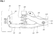
- FIGS. 1-3 and 4A-4C an example of a multi-link type rear suspension for describing the present disclosure is shown.
- the suspension for a vehicle is configured such that a first end of a suspension arm 10 is connected to a body frame 20 and a second end of the suspension arm 10 is connected to a knuckle 40 of a tire 30.
- the suspension arm 10 is a rear lower arm and the body frame 20 is a rear cross member.
- the present disclosure includes: a spring seat support arm 50 provided at the suspension arm 10 connecting the body frame 20 to the knuckle 40; a body member 60 positioned above the suspension arm 10; and a spring 70 configured to be supported, at opposite ends of the spring 70, by the spring seat support arm 50.
- the body member 60 preferably is a side member.
- the spring seat support arm 50 has a structure covered up by the suspension arm 10 and arranged along a longitudinal direction of the suspension arm 10.
- the spring seat support arm 50 is configured to be formed in a cantilever such that a first end of the spring seat support arm 50 is coupled to the suspension arm 10, and the spring 70 is supported by a second end of the spring seat support arm 50, the second end corresponding to a free end of the cantilever.
- the spring seat support arm 50 includes: a coupled portion 51 integrally coupled to the first end of the suspension arm 10; a rod portion 52 extending from the coupled portion 51 along the longitudinal direction of the suspension arm 10 and configured to be elastically deformed in response to external force; and a seat portion 53 provided at an end of the rod portion 52 and configured to support a lower end of the spring 70.
- the coupled portion 51 of the spring seat support arm 50 has a circular through hole 51a, and a suspension arm bush 80 is coupled to the through hole 51a by being forcibly inserted.
- a bolt 90 is fastened with a form of passing through the first end of the suspension arm 10, the suspension arm bush 80, and the body frame 20. Accordingly, the coupled portion 51 of the spring seat support arm 50 to which the suspension arm bush 80 is coupled is integrally coupled to the first end of the suspension arm 10 and is also coupled to the body frame 20 by the bolt 90.
- the spring seat support arm 50 is configured such that a spring pad 100 is coupled to an upper surface of the seat portion 53 and a lower end of the spring 70 is in contact with the spring pad 100.
- the spring pad 100 is preferably made of rubber or a material having elasticity in order to achieve impact absorption and noise prevention, but the present disclosure is not limited thereto.
- the spring seat support arm 50 includes a protrusion portion 54 formed to protrude outward from the coupled portion 51.
- the protrusion portion 54 When a rebound state is added in a full rebound state during driving, the protrusion portion 54 is rotatably moved toward the body frame 20 to be brought into contact with the body frame 20, and at this time, the spring seat support arm 50 is restrained to be fixed.
- a stopper 110 is configured to be fixed at a portion, which faces the protrusion portion 54 of the spring seat support arm 50, of the body frame 20, and as the protrusion portion 54 and the stopper 110 are brought into contact with each other, the spring seat support arm 50 may be restrained to be fixed.
- the stopper 110 into contact with the protrusion portion 54 of the spring seat support arm 50 is an elastic pad, so the stopper 110 may induce the impact absorption and the noise prevention during the contact with the protrusion portion 54.
- FIG. 4A shows a tolerance state
- FIG. 4B shows a full rebound state
- the seat portion 53 of the spring seat support arm 50 supports the lower end of the spring 70 while being in contact with the lower end of the suspension arm 10.
- the seat portion 53 of the spring seat support arm 50 also supports the lower end of the spring 70 while being in contact with the lower end of the suspension arm 10.
- FIG. 4C shows an additional rebound state in which a rebound state is added in the full rebound state of FIG. 4B .
- the protrusion portion 54 of the spring seat support arm 50 is brought into contact with the stopper 110 coupled to the body frame 20 so that the spring seat support arm 50 is restrained to be fixed, and the seat portion 53 is moved upward (direction toward the body member) by the elasticity of the rod portion 52 as the spring seat support arm 50 is restrained, and as a result, the seat portion 53 of the spring seat support arm 50 continuously supports the lower end of the spring 70 so that separation of the spring 70 may be prevented.
- the suspension according to the embodiment of the present disclosure is configured such that the lower end of the spring 70 is continuously supported by the spring seat support arm 50 even in a situation of departing from the range (spring freedom height) in which the spring 70 may be tensioned as a rebound state is added in the full rebound state. Accordingly, the separation of the spring 70 connecting the suspension arm 10 to the body member 60 is prevented, so that safety accidents, such as a vehicle rollover accident, may be prevented, and with improvement of vehicle stability improvement of merchantability may be improved.
- the embodiment of the present disclosure is configured to prevent the separation of a rear wheel spring during the full rebound state in a vehicle having a high wheel rate, such as the tuning where handling is a priority and the high performance vehicle, so rebound stroke may be additionally secured and excellent ride comfort may be secured by improving shock on impact even in the high performance vehicle.
- the present disclosure is configured such that the lower end of the spring 70 is physically supported using the spring seat support arm 50 at a time when the vehicle reaches the full rebound state so as to prevent the separation of the spring 70. Accordingly, with the structure not affecting hardness of the spring during driving operation, the suspension may be applied without the sense of difference.
Landscapes
- Engineering & Computer Science (AREA)
- Mechanical Engineering (AREA)
- Springs (AREA)
- Vehicle Body Suspensions (AREA)
- Transition And Organic Metals Composition Catalysts For Addition Polymerization (AREA)
Abstract
Description
- The present disclosure relates generally to a suspension for a vehicle, more particularly, to the suspension having a structure capable of preventing separation of a spring connecting a suspension arm to a body member when a rebound state is added in a full rebound state during driving.
- In a recent trend, tuning a vehicle hard has increased on the basis of European vehicles having excellent handling performance, and reduction of vehicle weight has been carried out to meet eco-friendly requirements.
- In order to tune a vehicle hard, wheel rate, i.e., hardness supporting a tire during applying vertical load to the tire, should be high, and in order to increase the wheel rate, hardness of a spring connecting a suspension arm to a body member should increase.
- When a weight of the vehicle is lightened, force compressing the spring is reduced and thereby the amount of compression of the spring is reduced.
- As described above, in a state in which the hardness of the spring increases in order to satisfy the vehicle property of being hard, when the weight of the vehicle is lightened in order to satisfy a property of the eco-friendly vehicle, the amount of the compression of the spring is further reduced when the vertical load is applied to the tire. As a result, when a rebound state is added in a full rebound state during driving (corresponding to state of departing from a range in which the spring may be tensioned, a state of departing from freedom height of the spring, and a state in which the tire passes through a deep puddle), there is a problem that the spring connecting the suspension arm to the body member may be separated, which may result in occurrence of an accident such as a vehicle rollover.
- In order to prevent separation of the spring, wheel stroke of the vehicle should be reduced, and the wheel stroke is a main factor affecting the vehicle performance and merchantability, but it is difficult to change the wheel stroke.
- The foregoing is intended merely to aid in the understanding of the background of the present disclosure, and is not intended to mean that the present disclosure falls within the purview of the related art that is already known to those skilled in the art.
- Accordingly, the present disclosure proposes a suspension for a vehicle, the suspension being configured to prevent separation of a spring connecting a suspension arm to a body member, even in a situation of departing from a range (spring freedom height) in which a spring may be tensioned, that is, a situation in which a rebound state is added in a full rebound state during driving, so that stability of the vehicle may be improved.
- In order to achieve the above objective, the suspension for a vehicle of the present disclosure includes: a spring seat support arm provided at a suspension arm connecting a body frame to a knuckle; and a spring configured to be supported, at opposite ends of the spring, by a body member and the spring seat support arm, the body member being located above the suspension arm.
- The spring seat support arm may be arranged along a longitudinal direction of the suspension arm and configured to have a shape of a cantilever such that a first end of the spring seat support arm may be coupled to the suspension arm and the spring may be supported by a second end of the spring seat support arm, the second end of the spring seat support arm corresponding to a free end of the cantilever.
- The spring seat support arm may include: a coupled portion integrally coupled to a first end of the suspension arm; a rod portion extending from the coupled portion along a longitudinal direction of the suspension arm and configured to be elastically deformed in response to external force; and a seat portion provided at an end of the rod portion and configured to support a lower end of the spring.
- The suspension for a vehicle may include: a spring pad coupled to the seat portion and configured to be in contact with the lower end of the spring.
- The spring seat support arm may include a protrusion portion formed to protrude outward from the coupled portion, wherein, when rebound is added in a full rebound state, as the protrusion portion is brought into contact with the body frame, the spring seat support arm may be restrained to be fixed.
- The suspension for a vehicle may include: a stopper securely provided at a portion, the portion facing the protrusion portion, of the body frame, wherein, when the protrusion portion and the stopper are brought into contact with each other, the spring seat support arm may be restrained to be fixed.
- The stopper may be a pad made of an elastic material in order to achieve impact absorption and noise prevention during the contact between the protrusion portion and the stopper.
- The seat portion may be configured such that, in a normal full rebound state without departing from a spring freedom height, the seat portion may support the lower end of the spring while being in contact with a lower end of the suspension arm by spring force; and when rebound is added in the full rebound state, the protrusion portion may be brought into contact with the stopper so that the spring seat support arm may be restrained to be fixed, and when the spring seat support arm is restrained, the seat portion may be moved upward by elasticity of the rod portion to continuously support the lower end of the spring, and thereby preventing separation of the spring.
- In the suspension of the present disclosure, even in a situation of departing from a range (spring freedom height) in which the spring may be tensioned as a rebound state is added in a full rebound state, the lower end of the spring is continuously supported by the spring seat support arm, so separation of the spring connecting the suspension arm to the body member can be prevented. Accordingly, occurrence of safety accidents such as a vehicle rollover accident can be prevented, and with improvement of vehicle stability, improvement of merchantability can be induced.
- The present disclosure is configured to prevent the separation of a rear wheel spring during the full rebound in a vehicle having a high wheel rate, such as tuning where handling is a priority and a high performance vehicle, so there are advantages that round stroke can be further secured and excellent ride comport can be secured by improving shock on impact even in a high performance vehicle.
- The present disclosure is configured such that the lower end of the spring is physically supported using the spring seat support arm at a time when the vehicle reaches the full rebound state so as to prevent the separation of the spring. Accordingly, with the structure not affecting hardness of the spring during driving operation, the suspension can be used without having the sense of difference.
- The above and other objectives, features, and other advantages of the present disclosure will be more clearly understood from the following detailed description when taken in conjunction with the accompanying drawings, in which:
-
FIG. 1 is a view showing a suspension for a vehicle having a spring seat support arm according to the present disclosure; -
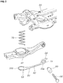
FIG. 2 is a disassembled view ofFIG. 1 ; -
FIG. 3 is a view showing the spring seat support arm coupled to a suspension arm according to the present disclosure; and -
FIG. 4A to 4C are views showing operation states of the suspension according to the present disclosure, whereinFIG. 4A shows a tolerance state,FIG. 4B shows a full rebound state, andFIG. 4C shows a state in which a rebound state is added in the full rebound state. - It is understood that the term "vehicle" or "vehicular" or other similar term as used herein is inclusive of motor vehicles in general such as passenger automobiles including sports utility vehicles (SUV), buses, trucks, various commercial vehicles, watercraft including a variety of boats and ships, aircraft, and the like, and includes hybrid vehicles, electric vehicles, plug-in hybrid electric vehicles, hydrogen-powered vehicles and other alternative fuel vehicles (e.g. fuels derived from resources other than petroleum). As referred to herein, a hybrid vehicle is a vehicle that has two or more sources of power, for example both gasoline-powered and electric-powered vehicles.
- The terminology used herein is for the purpose of describing particular embodiments only and is not intended to be limiting of the disclosure. As used herein, the singular forms "a," "an" and "the" are intended to include the plural forms as well, unless the context clearly indicates otherwise. It will be further understood that the terms "comprises" and/or "comprising," when used in this specification, specify the presence of stated features, integers, steps, operations, elements, and/or components, but do not preclude the presence or addition of one or more other features, integers, steps, operations, elements, components, and/or groups thereof. As used herein, the term "and/or" includes any and all combinations of one or more of the associated listed items. Throughout the specification, unless explicitly described to the contrary, the word "comprise" and variations such as "comprises" or "comprising" will be understood to imply the inclusion of stated elements but not the exclusion of any other elements. In addition, the terms "unit", "-er", "-or", and "module" described in the specification mean units for processing at least one function and operation, and can be implemented by hardware components or software components and combinations thereof.
- Further, the control logic of the present disclosure may be embodied as non-transitory computer readable media on a computer readable medium containing executable program instructions executed by a processor, controller or the like. Examples of computer readable media include, but are not limited to, ROM, RAM, compact disc (CD)-ROMs, magnetic tapes, floppy disks, flash drives, smart cards and optical data storage devices. The computer readable medium can also be distributed in network coupled computer systems so that the computer readable media is stored and executed in a distributed fashion, e.g., by a telematics server or a Controller Area Network (CAN).
- In the following description, the structural or functional description specified to exemplary embodiments according to the concept of the present disclosure is intended to describe the exemplary embodiment, so it should be understood that the present disclosure may be variously embodied, without being limited to the exemplary embodiments.
- An embodiment described herein may be changed in various ways and various shapes, so specific embodiments are shown in the drawings and will be described in detail in this specification. However, it should be understood that the exemplary embodiment according to the concept of the present disclosure is not limited to the embodiment which will be described hereinbelow with reference to the accompanying drawings, but all of modifications, equivalents, and substitutions are included in the scope and spirit of the disclosure.
- It will be understood that, although the terms first and/or second, etc. may be used herein to describe various elements, these elements should not be limited by these terms. These terms are only used to distinguish one element from another element. For instance, a first element discussed below could be termed a second element without departing from the teachings of the present disclosure. Similarly, the second element could also be termed the first element.
- It is to be understood that when one element is referred to as being "connected to" or "coupled to" another element, it may be connected directly to or coupled directly to another element or be connected to or coupled to another element, having the other element intervening therebetween. On the other hand, it is to be understood that when one element is referred to as being "connected directly to" or "coupled directly to" another element, it may be connected to or coupled to another element without the other element intervening therebetween. Further, the terms used herein to describe a relationship between elements, that is, "between", "directly between", "adjacent" or "directly adjacent" should be interpreted in the same manner as those described above.
- The terminology used herein is for the purpose of describing a particular embodiment only and is not intended to limit the present disclosure. Singular forms are intended to include plural forms unless the context clearly indicates otherwise.
- Unless otherwise defmed, all terms including technical and scientific terms used herein have the same meaning as commonly understood by those skilled in the art to which the present disclosure belongs. It must be understood that the terms defined by the dictionary are identical with the meanings within the context of the related art, and they should not be ideally or excessively formally defined unless the context clearly dictates otherwise.
- A control part (controller) according to the exemplary embodiment of the present disclosure may be realized by a nonvolatile memory (not shown), which consists of an algorithm configured to control operations of various components of a vehicle or data regarding software instructions to play the algorithm, and a processor (not shown), which is configured to perform operations described below using the data stored in the memory. Here, the memory and processor may be realized as separate chips. Alternately, the memory and processor may be realized as an integrated single chip. The processor may take one or more form.
- Hereinbelow, a suspension for a vehicle according to an exemplary embodiment of the present disclosure will be described with reference to accompanying drawings.
- In
FIGS. 1-3 and4A-4C , an example of a multi-link type rear suspension for describing the present disclosure is shown. - As shown in
FIGS. 1-3 and4A-4C , according to the present disclosure, the suspension for a vehicle is configured such that a first end of asuspension arm 10 is connected to abody frame 20 and a second end of thesuspension arm 10 is connected to aknuckle 40 of atire 30. - The
suspension arm 10 is a rear lower arm and thebody frame 20 is a rear cross member. - The present disclosure includes: a spring
seat support arm 50 provided at thesuspension arm 10 connecting thebody frame 20 to theknuckle 40; abody member 60 positioned above thesuspension arm 10; and aspring 70 configured to be supported, at opposite ends of thespring 70, by the springseat support arm 50. - The
body member 60 preferably is a side member. - The spring
seat support arm 50 has a structure covered up by thesuspension arm 10 and arranged along a longitudinal direction of thesuspension arm 10. - The spring
seat support arm 50 is configured to be formed in a cantilever such that a first end of the springseat support arm 50 is coupled to thesuspension arm 10, and thespring 70 is supported by a second end of the springseat support arm 50, the second end corresponding to a free end of the cantilever. - That is, the spring
seat support arm 50 includes: a coupledportion 51 integrally coupled to the first end of thesuspension arm 10; arod portion 52 extending from the coupledportion 51 along the longitudinal direction of thesuspension arm 10 and configured to be elastically deformed in response to external force; and aseat portion 53 provided at an end of therod portion 52 and configured to support a lower end of thespring 70. - The coupled
portion 51 of the springseat support arm 50 has a circular throughhole 51a, and asuspension arm bush 80 is coupled to the throughhole 51a by being forcibly inserted. - A
bolt 90 is fastened with a form of passing through the first end of thesuspension arm 10, thesuspension arm bush 80, and thebody frame 20. Accordingly, the coupledportion 51 of the springseat support arm 50 to which thesuspension arm bush 80 is coupled is integrally coupled to the first end of thesuspension arm 10 and is also coupled to thebody frame 20 by thebolt 90. - The spring
seat support arm 50 is configured such that aspring pad 100 is coupled to an upper surface of theseat portion 53 and a lower end of thespring 70 is in contact with thespring pad 100. - The
spring pad 100 is preferably made of rubber or a material having elasticity in order to achieve impact absorption and noise prevention, but the present disclosure is not limited thereto. - The spring
seat support arm 50 includes aprotrusion portion 54 formed to protrude outward from the coupledportion 51. - When a rebound state is added in a full rebound state during driving, the
protrusion portion 54 is rotatably moved toward thebody frame 20 to be brought into contact with thebody frame 20, and at this time, the springseat support arm 50 is restrained to be fixed. - According to the present disclosure, a
stopper 110 is configured to be fixed at a portion, which faces theprotrusion portion 54 of the springseat support arm 50, of thebody frame 20, and as theprotrusion portion 54 and thestopper 110 are brought into contact with each other, the springseat support arm 50 may be restrained to be fixed. - When the
protrusion portion 54 of the springseat support arm 50 and thebody frame 20 are brought into direct contact with each other without thestopper 110, due to contact between steel and steel, impact and noise are generated. - According to the present disclosure, the
stopper 110 into contact with theprotrusion portion 54 of the springseat support arm 50 is an elastic pad, so thestopper 110 may induce the impact absorption and the noise prevention during the contact with theprotrusion portion 54. -
FIG. 4A shows a tolerance state, andFIG. 4B shows a full rebound state. - In the tolerance state or the normal full rebound state without departing from a range (spring freedom height) in which the spring may be tensioned, by spring force, the
seat portion 53 of the springseat support arm 50 supports the lower end of thespring 70 while being in contact with the lower end of thesuspension arm 10. - Furthermore, in a normal full bump state without departing from the range (spring freedom height) in which the spring may be tensioned, by the spring force, the
seat portion 53 of the springseat support arm 50 also supports the lower end of thespring 70 while being in contact with the lower end of thesuspension arm 10. -
FIG. 4C shows an additional rebound state in which a rebound state is added in the full rebound state ofFIG. 4B . - When a rebound state is added in the full rebound state in
FIG. 4B , thesuspension arm 10 further rotates counterclockwise on thebolt 90 so that the amount of downward movement increases, as shown in the drawing (arrow M1). - However, the
protrusion portion 54 of the springseat support arm 50 is brought into contact with thestopper 110 coupled to thebody frame 20 so that the springseat support arm 50 is restrained to be fixed, and theseat portion 53 is moved upward (direction toward the body member) by the elasticity of therod portion 52 as the springseat support arm 50 is restrained, and as a result, theseat portion 53 of the springseat support arm 50 continuously supports the lower end of thespring 70 so that separation of thespring 70 may be prevented. - As described above, the suspension according to the embodiment of the present disclosure is configured such that the lower end of the
spring 70 is continuously supported by the springseat support arm 50 even in a situation of departing from the range (spring freedom height) in which thespring 70 may be tensioned as a rebound state is added in the full rebound state. Accordingly, the separation of thespring 70 connecting thesuspension arm 10 to thebody member 60 is prevented, so that safety accidents, such as a vehicle rollover accident, may be prevented, and with improvement of vehicle stability improvement of merchantability may be improved. - The embodiment of the present disclosure is configured to prevent the separation of a rear wheel spring during the full rebound state in a vehicle having a high wheel rate, such as the tuning where handling is a priority and the high performance vehicle, so rebound stroke may be additionally secured and excellent ride comfort may be secured by improving shock on impact even in the high performance vehicle.
- Furthermore, the present disclosure is configured such that the lower end of the
spring 70 is physically supported using the springseat support arm 50 at a time when the vehicle reaches the full rebound state so as to prevent the separation of thespring 70. Accordingly, with the structure not affecting hardness of the spring during driving operation, the suspension may be applied without the sense of difference. - Although a preferred embodiment of the present disclosure has been described for illustrative purposes, those skilled in the art will appreciate that various modifications, additions and substitutions are possible, without departing from the scope and spirit of the disclosure as disclosed in the accompanying claims.
Claims (8)
- A suspension for a vehicle, the suspension comprising:a spring seat support arm provided at a suspension arm connecting a body frame to a knuckle; anda spring configured to be supported, at opposite ends of the spring, by a body member and the spring seat support arm, the body member being located above the suspension arm.
- The suspension for a vehicle of claim 1, wherein the spring seat support arm is arranged along a longitudinal direction of the suspension arm and configured to have a shape of a cantilever such that a first end of the spring seat support arm is coupled to the suspension arm and the spring is supported by a second end of the spring seat support arm, the second end of the spring seat support arm corresponding to a free end of the cantilever.
- The suspension for a vehicle of claim 1, wherein the spring seat support arm comprises:a coupled portion integrally coupled to a first end of the suspension arm;a rod portion extending from the coupled portion along a longitudinal direction of the suspension arm and configured to be elastically deformed in response to external force; anda seat portion provided at an end of the rod portion and configured to support a lower end of the spring.
- The suspension for a vehicle of claim 3, further comprising:
a spring pad coupled to the seat portion and configured to be in contact with the lower end of the spring. - The suspension for a vehicle of claim 3, wherein the spring seat support arm further comprises a protrusion portion formed to protrude outward from the coupled portion,
wherein, when rebound is added in a full rebound state, as the protrusion portion is brought into contact with the body frame, the spring seat support arm is restrained to be fixed. - The suspension for a vehicle of claim 5, further comprising:a stopper securely provided at a portion, the portion facing the protrusion portion, of the body frame,wherein, when the protrusion portion and the stopper are brought into contact with each other, the spring seat support arm is restrained to be fixed.
- The suspension for a vehicle of claim 6, wherein the stopper is a pad made of an elastic material in order to achieve impact absorption and noise prevention during the contact between the protrusion portion and the stopper.
- The suspension for a vehicle of claim 6, wherein the seat portion is configured such that, in a normal full rebound state without departing from a spring freedom height, the seat portion supports the lower end of the spring while being in contact with a lower end of the suspension arm by spring force; and
when rebound is added in the full rebound state, the protrusion portion is brought into contact with the stopper so that the spring seat support arm is restrained to be fixed, and when the spring seat support arm is restrained, the seat portion is moved upward by elasticity of the rod portion to continuously support the lower end of the spring, and thereby preventing separation of the spring.
Applications Claiming Priority (1)
| Application Number | Priority Date | Filing Date | Title |
|---|---|---|---|
| KR1020210032253A KR102929653B1 (en) | 2021-03-11 | 2021-03-11 | Suspension for vehicle |
Publications (2)
| Publication Number | Publication Date |
|---|---|
| EP4056392A1 true EP4056392A1 (en) | 2022-09-14 |
| EP4056392B1 EP4056392B1 (en) | 2025-11-05 |
Family
ID=77774733
Family Applications (1)
| Application Number | Title | Priority Date | Filing Date |
|---|---|---|---|
| EP21196759.1A Active EP4056392B1 (en) | 2021-03-11 | 2021-09-15 | Suspension for vehicle |
Country Status (3)
| Country | Link |
|---|---|
| US (1) | US11511580B2 (en) |
| EP (1) | EP4056392B1 (en) |
| KR (1) | KR102929653B1 (en) |
Families Citing this family (3)
| Publication number | Priority date | Publication date | Assignee | Title |
|---|---|---|---|---|
| EP3722121B1 (en) * | 2019-04-11 | 2021-11-24 | Autotech Engineering Deutschland GmbH | One-shell suspension arm |
| KR102929654B1 (en) * | 2021-03-11 | 2026-02-20 | 현대자동차주식회사 | Suspension for vehicle |
| WO2023129583A1 (en) * | 2021-12-29 | 2023-07-06 | Am General Llc | Lower control arm and lower control arm assembly |
Citations (3)
| Publication number | Priority date | Publication date | Assignee | Title |
|---|---|---|---|---|
| US1777565A (en) * | 1927-06-10 | 1930-10-07 | Hulley Albert | Suspension for vehicles |
| FR2100284A5 (en) * | 1970-07-07 | 1972-03-17 | Burgt Gerrit V D | |
| JP2004216922A (en) * | 2003-01-09 | 2004-08-05 | Honda Motor Co Ltd | Vehicle suspension device |
Family Cites Families (17)
| Publication number | Priority date | Publication date | Assignee | Title |
|---|---|---|---|---|
| US2507980A (en) * | 1947-08-18 | 1950-05-16 | Walter H Knapp | Independent wheel suspension |
| US2839293A (en) * | 1955-06-28 | 1958-06-17 | Raymond P Cover | Auxiliary spring for wheel mounting |
| GB1084157A (en) * | 1965-06-17 | |||
| US4170373A (en) * | 1978-04-06 | 1979-10-09 | General Signal Corporation | Wire suspension arm |
| US4456282A (en) * | 1981-12-24 | 1984-06-26 | Ford Motor Company | Independent rear wheel suspension with a toe angle controlling trailing arm |
| US5409254A (en) * | 1992-05-11 | 1995-04-25 | A. O. Smith Corporation | Rear suspension with aligned coil springs and twist beam axle |
| DE4331365A1 (en) * | 1993-09-15 | 1995-03-16 | Bayerische Motoren Werke Ag | Vehicle wheel suspension in shock absorber design |
| KR100264649B1 (en) * | 1996-11-29 | 2000-09-01 | 정몽규 | McPherson Independent Suspension System for Automobile |
| US20030116935A1 (en) * | 2001-12-26 | 2003-06-26 | Adam Zadok | Anti-roll vehicle suspension |
| JP4177669B2 (en) * | 2003-01-08 | 2008-11-05 | 本田技研工業株式会社 | Vehicle suspension system |
| KR100527711B1 (en) * | 2003-06-03 | 2005-11-09 | 현대자동차주식회사 | lower arm structure of a vehicle |
| JP4360227B2 (en) * | 2004-02-19 | 2009-11-11 | マツダ株式会社 | Suspension device |
| KR100828788B1 (en) * | 2006-09-28 | 2008-05-09 | 현대자동차주식회사 | Spring buckling prevention device of vehicle suspension |
| KR20080052760A (en) | 2006-12-08 | 2008-06-12 | 현대자동차주식회사 | Lower spring seat adjuster of suspension |
| DE102013205335A1 (en) * | 2013-03-26 | 2014-10-02 | Ford Global Technologies, Llc | Independent suspension for the non-driven wheels of a vehicle |
| KR102261281B1 (en) * | 2015-11-24 | 2021-06-04 | 현대자동차 주식회사 | Lower arm of suspension for vehicle |
| DE102019102493A1 (en) * | 2019-01-31 | 2020-08-06 | Benteler Automobiltechnik Gmbh | Motor vehicle driver |
-
2021
- 2021-03-11 KR KR1020210032253A patent/KR102929653B1/en active Active
- 2021-09-13 US US17/473,397 patent/US11511580B2/en active Active
- 2021-09-15 EP EP21196759.1A patent/EP4056392B1/en active Active
Patent Citations (3)
| Publication number | Priority date | Publication date | Assignee | Title |
|---|---|---|---|---|
| US1777565A (en) * | 1927-06-10 | 1930-10-07 | Hulley Albert | Suspension for vehicles |
| FR2100284A5 (en) * | 1970-07-07 | 1972-03-17 | Burgt Gerrit V D | |
| JP2004216922A (en) * | 2003-01-09 | 2004-08-05 | Honda Motor Co Ltd | Vehicle suspension device |
Also Published As
| Publication number | Publication date |
|---|---|
| US20220288986A1 (en) | 2022-09-15 |
| KR102929653B1 (en) | 2026-02-20 |
| EP4056392B1 (en) | 2025-11-05 |
| KR20220127660A (en) | 2022-09-20 |
| US11511580B2 (en) | 2022-11-29 |
Similar Documents
| Publication | Publication Date | Title |
|---|---|---|
| US11511580B2 (en) | Suspension for vehicle | |
| US11001113B2 (en) | Dual-rate leaf spring suspension for a vehicle | |
| CA2706871C (en) | Shackle assembly | |
| US11407267B2 (en) | Silencer for leaf spring for commercial vehicle | |
| KR102617707B1 (en) | Coil spring fixing device for vehicle | |
| CN111907278A (en) | vehicle rear suspension | |
| EP4056394B1 (en) | Suspension system for vehicle | |
| EP4056393B1 (en) | Suspension for vehicle | |
| CN110626138B (en) | Composite material type multi-plate spring suspension for vehicle | |
| US5857687A (en) | Bump stop seat structure | |
| US11820190B2 (en) | Coupled torsion beam axle type rear suspension system | |
| US5005855A (en) | Insulator device for strut type suspension system of automobile | |
| KR20240088369A (en) | Suspension for vehicle | |
| JP2990590B2 (en) | Axle suspension | |
| CN223199857U (en) | Battery box suspension vibration damping mechanism | |
| CN219312448U (en) | Novel suspension system and car | |
| CN115723499B (en) | Suspension system with rebound control for a vehicle | |
| US12311714B1 (en) | Tension leaf with auxiliary spring | |
| US12447787B2 (en) | Suspension system for a vehicle | |
| CN217495771U (en) | Front axle air suspension assembly and commercial vehicle | |
| CN2849318Y (en) | Bow steel strong force automobile buffer | |
| CN119974952A (en) | Tank fixing assembly and control method thereof | |
| JPH023519A (en) | Stabilizer for automobile | |
| CN118238563A (en) | Torsion beam suspension assembly and vehicle | |
| KR20140077277A (en) | Structure for Reducing Noise for Suspension Bumper Stopper |
Legal Events
| Date | Code | Title | Description |
|---|---|---|---|
| PUAI | Public reference made under article 153(3) epc to a published international application that has entered the european phase |
Free format text: ORIGINAL CODE: 0009012 |
|
| STAA | Information on the status of an ep patent application or granted ep patent |
Free format text: STATUS: THE APPLICATION HAS BEEN PUBLISHED |
|
| AK | Designated contracting states |
Kind code of ref document: A1 Designated state(s): AL AT BE BG CH CY CZ DE DK EE ES FI FR GB GR HR HU IE IS IT LI LT LU LV MC MK MT NL NO PL PT RO RS SE SI SK SM TR |
|
| STAA | Information on the status of an ep patent application or granted ep patent |
Free format text: STATUS: REQUEST FOR EXAMINATION WAS MADE |
|
| 17P | Request for examination filed |
Effective date: 20221012 |
|
| RBV | Designated contracting states (corrected) |
Designated state(s): AL AT BE BG CH CY CZ DE DK EE ES FI FR GB GR HR HU IE IS IT LI LT LU LV MC MK MT NL NO PL PT RO RS SE SI SK SM TR |
|
| STAA | Information on the status of an ep patent application or granted ep patent |
Free format text: STATUS: EXAMINATION IS IN PROGRESS |
|
| 17Q | First examination report despatched |
Effective date: 20221212 |
|
| P01 | Opt-out of the competence of the unified patent court (upc) registered |
Free format text: CASE NUMBER: UPC_APP_119662/2023 Effective date: 20230510 |
|
| GRAP | Despatch of communication of intention to grant a patent |
Free format text: ORIGINAL CODE: EPIDOSNIGR1 |
|
| STAA | Information on the status of an ep patent application or granted ep patent |
Free format text: STATUS: GRANT OF PATENT IS INTENDED |
|
| GRAJ | Information related to disapproval of communication of intention to grant by the applicant or resumption of examination proceedings by the epo deleted |
Free format text: ORIGINAL CODE: EPIDOSDIGR1 |
|
| STAA | Information on the status of an ep patent application or granted ep patent |
Free format text: STATUS: EXAMINATION IS IN PROGRESS |
|
| INTG | Intention to grant announced |
Effective date: 20250602 |
|
| INTC | Intention to grant announced (deleted) | ||
| GRAP | Despatch of communication of intention to grant a patent |
Free format text: ORIGINAL CODE: EPIDOSNIGR1 |
|
| STAA | Information on the status of an ep patent application or granted ep patent |
Free format text: STATUS: GRANT OF PATENT IS INTENDED |
|
| INTG | Intention to grant announced |
Effective date: 20250718 |
|
| GRAS | Grant fee paid |
Free format text: ORIGINAL CODE: EPIDOSNIGR3 |
|
| GRAA | (expected) grant |
Free format text: ORIGINAL CODE: 0009210 |
|
| STAA | Information on the status of an ep patent application or granted ep patent |
Free format text: STATUS: THE PATENT HAS BEEN GRANTED |
|
| AK | Designated contracting states |
Kind code of ref document: B1 Designated state(s): AL AT BE BG CH CY CZ DE DK EE ES FI FR GB GR HR HU IE IS IT LI LT LU LV MC MK MT NL NO PL PT RO RS SE SI SK SM TR |
|
| REG | Reference to a national code |
Ref country code: CH Ref legal event code: F10 Free format text: ST27 STATUS EVENT CODE: U-0-0-F10-F00 (AS PROVIDED BY THE NATIONAL OFFICE) Effective date: 20251105 Ref country code: GB Ref legal event code: FG4D |
|
| REG | Reference to a national code |
Ref country code: DE Ref legal event code: R096 Ref document number: 602021041667 Country of ref document: DE |
|
| REG | Reference to a national code |
Ref country code: IE Ref legal event code: FG4D |
|
| REG | Reference to a national code |
Ref country code: NL Ref legal event code: MP Effective date: 20251105 |
|
| PG25 | Lapsed in a contracting state [announced via postgrant information from national office to epo] |
Ref country code: ES Free format text: LAPSE BECAUSE OF FAILURE TO SUBMIT A TRANSLATION OF THE DESCRIPTION OR TO PAY THE FEE WITHIN THE PRESCRIBED TIME-LIMIT Effective date: 20251105 |
|
| REG | Reference to a national code |
Ref country code: LT Ref legal event code: MG9D |
|
| PG25 | Lapsed in a contracting state [announced via postgrant information from national office to epo] |
Ref country code: NO Free format text: LAPSE BECAUSE OF FAILURE TO SUBMIT A TRANSLATION OF THE DESCRIPTION OR TO PAY THE FEE WITHIN THE PRESCRIBED TIME-LIMIT Effective date: 20260205 |
|
| PG25 | Lapsed in a contracting state [announced via postgrant information from national office to epo] |
Ref country code: AT Free format text: LAPSE BECAUSE OF FAILURE TO SUBMIT A TRANSLATION OF THE DESCRIPTION OR TO PAY THE FEE WITHIN THE PRESCRIBED TIME-LIMIT Effective date: 20251105 Ref country code: HR Free format text: LAPSE BECAUSE OF FAILURE TO SUBMIT A TRANSLATION OF THE DESCRIPTION OR TO PAY THE FEE WITHIN THE PRESCRIBED TIME-LIMIT Effective date: 20251105 Ref country code: FI Free format text: LAPSE BECAUSE OF FAILURE TO SUBMIT A TRANSLATION OF THE DESCRIPTION OR TO PAY THE FEE WITHIN THE PRESCRIBED TIME-LIMIT Effective date: 20251105 |
|
| REG | Reference to a national code |
Ref country code: AT Ref legal event code: MK05 Ref document number: 1853986 Country of ref document: AT Kind code of ref document: T Effective date: 20251105 |
|
| PG25 | Lapsed in a contracting state [announced via postgrant information from national office to epo] |
Ref country code: NL Free format text: LAPSE BECAUSE OF FAILURE TO SUBMIT A TRANSLATION OF THE DESCRIPTION OR TO PAY THE FEE WITHIN THE PRESCRIBED TIME-LIMIT Effective date: 20251105 |
|
| PG25 | Lapsed in a contracting state [announced via postgrant information from national office to epo] |
Ref country code: RS Free format text: LAPSE BECAUSE OF FAILURE TO SUBMIT A TRANSLATION OF THE DESCRIPTION OR TO PAY THE FEE WITHIN THE PRESCRIBED TIME-LIMIT Effective date: 20260205 |
|
| PG25 | Lapsed in a contracting state [announced via postgrant information from national office to epo] |
Ref country code: IS Free format text: LAPSE BECAUSE OF FAILURE TO SUBMIT A TRANSLATION OF THE DESCRIPTION OR TO PAY THE FEE WITHIN THE PRESCRIBED TIME-LIMIT Effective date: 20260305 |
|
| PG25 | Lapsed in a contracting state [announced via postgrant information from national office to epo] |
Ref country code: PT Free format text: LAPSE BECAUSE OF FAILURE TO SUBMIT A TRANSLATION OF THE DESCRIPTION OR TO PAY THE FEE WITHIN THE PRESCRIBED TIME-LIMIT Effective date: 20260305 |
|
| PG25 | Lapsed in a contracting state [announced via postgrant information from national office to epo] |
Ref country code: PL Free format text: LAPSE BECAUSE OF FAILURE TO SUBMIT A TRANSLATION OF THE DESCRIPTION OR TO PAY THE FEE WITHIN THE PRESCRIBED TIME-LIMIT Effective date: 20251105 |
|
| PG25 | Lapsed in a contracting state [announced via postgrant information from national office to epo] |
Ref country code: LV Free format text: LAPSE BECAUSE OF FAILURE TO SUBMIT A TRANSLATION OF THE DESCRIPTION OR TO PAY THE FEE WITHIN THE PRESCRIBED TIME-LIMIT Effective date: 20251105 |