EP4056330A1 - Robot control method - Google Patents
Robot control method Download PDFInfo
- Publication number
- EP4056330A1 EP4056330A1 EP20885590.8A EP20885590A EP4056330A1 EP 4056330 A1 EP4056330 A1 EP 4056330A1 EP 20885590 A EP20885590 A EP 20885590A EP 4056330 A1 EP4056330 A1 EP 4056330A1
- Authority
- EP
- European Patent Office
- Prior art keywords
- compensation amount
- workpiece
- arm
- teaching point
- joint
- Prior art date
- Legal status (The legal status is an assumption and is not a legal conclusion. Google has not performed a legal analysis and makes no representation as to the accuracy of the status listed.)
- Granted
Links
Images



Classifications
-
- B—PERFORMING OPERATIONS; TRANSPORTING
- B25—HAND TOOLS; PORTABLE POWER-DRIVEN TOOLS; MANIPULATORS
- B25J—MANIPULATORS; CHAMBERS PROVIDED WITH MANIPULATION DEVICES
- B25J9/00—Program-controlled manipulators
- B25J9/16—Program controls
- B25J9/1628—Program controls characterised by the control loop
- B25J9/1638—Program controls characterised by the control loop compensation for arm bending/inertia, pay load weight/inertia
-
- B—PERFORMING OPERATIONS; TRANSPORTING
- B25—HAND TOOLS; PORTABLE POWER-DRIVEN TOOLS; MANIPULATORS
- B25J—MANIPULATORS; CHAMBERS PROVIDED WITH MANIPULATION DEVICES
- B25J9/00—Program-controlled manipulators
- B25J9/16—Program controls
- B25J9/1628—Program controls characterised by the control loop
- B25J9/1641—Program controls characterised by the control loop compensation for backlash, friction, compliance, elasticity in the joints
-
- B—PERFORMING OPERATIONS; TRANSPORTING
- B25—HAND TOOLS; PORTABLE POWER-DRIVEN TOOLS; MANIPULATORS
- B25J—MANIPULATORS; CHAMBERS PROVIDED WITH MANIPULATION DEVICES
- B25J9/00—Program-controlled manipulators
- B25J9/10—Program-controlled manipulators characterised by positioning means for manipulator elements
-
- B—PERFORMING OPERATIONS; TRANSPORTING
- B25—HAND TOOLS; PORTABLE POWER-DRIVEN TOOLS; MANIPULATORS
- B25J—MANIPULATORS; CHAMBERS PROVIDED WITH MANIPULATION DEVICES
- B25J9/00—Program-controlled manipulators
- B25J9/16—Program controls
- B25J9/1612—Program controls characterised by the hand, wrist, grip control
-
- B—PERFORMING OPERATIONS; TRANSPORTING
- B25—HAND TOOLS; PORTABLE POWER-DRIVEN TOOLS; MANIPULATORS
- B25J—MANIPULATORS; CHAMBERS PROVIDED WITH MANIPULATION DEVICES
- B25J9/00—Program-controlled manipulators
- B25J9/16—Program controls
- B25J9/1628—Program controls characterised by the control loop
- B25J9/163—Program controls characterised by the control loop learning, adaptive, model based, rule based expert control
-
- B—PERFORMING OPERATIONS; TRANSPORTING
- B25—HAND TOOLS; PORTABLE POWER-DRIVEN TOOLS; MANIPULATORS
- B25J—MANIPULATORS; CHAMBERS PROVIDED WITH MANIPULATION DEVICES
- B25J9/00—Program-controlled manipulators
- B25J9/16—Program controls
- B25J9/1656—Program controls characterised by programming, planning systems for manipulators
- B25J9/1664—Program controls characterised by programming, planning systems for manipulators characterised by motion, path, trajectory planning
-
- G—PHYSICS
- G05—CONTROLLING; REGULATING
- G05B—CONTROL OR REGULATING SYSTEMS IN GENERAL; FUNCTIONAL ELEMENTS OF SUCH SYSTEMS; MONITORING OR TESTING ARRANGEMENTS FOR SUCH SYSTEMS OR ELEMENTS
- G05B2219/00—Program-control systems
- G05B2219/30—Nc systems
- G05B2219/39—Robotics, robotics to robotics hand
- G05B2219/39186—Flexible joint
-
- G—PHYSICS
- G05—CONTROLLING; REGULATING
- G05B—CONTROL OR REGULATING SYSTEMS IN GENERAL; FUNCTIONAL ELEMENTS OF SUCH SYSTEMS; MONITORING OR TESTING ARRANGEMENTS FOR SUCH SYSTEMS OR ELEMENTS
- G05B2219/00—Program-control systems
- G05B2219/30—Nc systems
- G05B2219/43—Speed, acceleration, deceleration control ADC
- G05B2219/43058—Limitation of acceleration, permissible, tolerable acceleration
Definitions
- the present disclosure relates to a robot control method.
- Patent Literatures 1 and 2 Conventionally, a robot control method that drives each joint of a robot based on teaching data has been known (see, for example, Patent Literatures 1 and 2).
- the robot is driven via a speed reducer provided in the joint, there is a problem that the speed reducer and a bearing are elastically deformed to cause deflection in an arm and an absolute positional accuracy becomes difficult to be ensured.
- Patent Literature 1 discloses a configuration in which load information is added to each piece of teaching point data, and deflection compensation is performed while a compensation amount for each teaching point is switched according to the load information.
- Patent Literature 2 discloses a configuration in which teaching points are created according to the presence of a gripped object, and a robot is operated based on teaching point data to which information on the presence of the gripped object is added.
- the compensation amount of the arm is switched in the state of the hand still gripping the workpiece. As a result, there is a risk that the workpiece is damaged by being pressed against the workbench.
- the acceleration of the arm generated based on the change in the compensation amount also becomes large.
- the arm possibly moves by a width equal to or larger than the compensation amount, and there is a risk of the hand coming into contact with the workbench.
- the present disclosure has been made in view of the above point, and an object of the present disclosure is to suppress a malfunction that occurs when deflection of an arm is compensated after a workpiece is brought into a non-gripping state.
- the present disclosure is directed to a robot control method of operating an arm of a robot having a plurality of joints based on a predetermined operation program, and has taken the following solution.
- a first aspect of the invention includes:
- the deflection compensation of the arm when the workpiece is brought into the non-gripping state after the deflection compensation of the arm is performed in the gripping state of the workpiece, the deflection compensation of the arm is performed in the non-gripping state of the workpiece.
- the deflection compensation of the arm in the non-gripping state of the workpiece is performed while a compensation amount is changed to gradually decrease, while the gripping part is moved from the first teaching point to the second teaching point.
- the compensation amount is gradually decreased according to the elapsed time or the movement amount of the arm while the gripping part is moved from the first teaching point to the second teaching point.
- the deflection compensation of the arm is performed based on the third compensation amount that linearly changes so as to gradually decrease from the first compensation amount toward the second compensation amount.
- the compensation amount of the arm can be gently varied, and unintended movement of the arm can be suppressed.
- the third compensation amount changes in a curved shape at a boundary position between the first compensation amount and the third compensation amount and at a boundary position between the third compensation amount and the second compensation amount.
- the boundary position between the first compensation amount and the third compensation amount and the boundary position between the third compensation amount and the second compensation amount change in a curved shape.
- the compensation amount of the arm can be more gently varied, and unintended movement of the arm can be suppressed.
- the joint is operated based on a fourth compensation amount that changes more gently than the third compensation amount, in a case where a time from when the workpiece is brought into the non-gripping state to when the gripping part starts to move from the first teaching point to the second teaching point is shorter than a predetermined time.
- the deflection compensation of the arm is performed based on the fourth compensation amount that changes more gently than the third compensation amount.
- the compensation amount of the arm can be more gently varied, and unintended movement of the arm can be suppressed.
- the joint is operated based on a fourth compensation amount that changes more gently than the third compensation amount, in a case where a distance between the gripping part and the first teaching point is shorter than a predetermined distance.
- the deflection compensation of the arm is performed based on the fourth compensation amount that changes more gently than the third compensation amount.
- the compensation amount of the arm can be more gently varied, and unintended movement of the arm can be suppressed.
- the arm has an acceleration within a range of allowable acceleration of the arm, the acceleration being generated based on a change in the compensation amount.
- the acceleration of the arm generated based on the change in the compensation amount is set within the range of the allowable acceleration of the arm. As a result, the arm can be suppressed from moving by a width exceeding the compensation amount.
- robot 1 includes six-axis articulated robot arm 10 and controller 20 that controls the operation of robot arm 10. Robot 1 transfers workpiece W to and from workbench 5.
- Robot arm 10 includes base 11, shoulder 12, lower arm 13, first upper arm 14, second upper arm 15, wrist 16, and attaching part 17.
- Shoulder 12 is supported on base 11 so as to be turnable in the horizontal direction about first joint J1.
- Lower arm 13 is supported on shoulder 12 so as to be turnable in the vertical direction about second joint J2.
- First upper arm 14 is supported on lower arm 13 so as to be turnable in the vertical direction about third joint J3.
- Second upper arm 15 is supported on the tip of first upper arm 14 so as to be torsionally rotatable about fourth joint J4.
- Wrist 16 is supported on second upper arm 15 so as to be turnable in the vertical direction about fifth joint J5.
- Attaching part 17 is supported on wrist 16 so as to be torsionally rotatable about sixth joint J6.
- Hand 18 grips workpiece W is attached to attaching part 17.
- Controller 20 controls driving of the actuators of first joint J1 to sixth joint J6 based on an operation program input in advance by teaching or the like so that first joint J1 to sixth joint J6 reach target positions (command angles), respectively.
- Robot arm 10 moves workpiece W gripped by hand 18 to a first teaching point of workbench 5, opens hand 18 at the first teaching point, and brings workpiece W into the non-gripping state. Thereafter, robot arm 10 moves hand 18 toward a second teaching point positioned away from the first teaching point in the non-gripping state of workpiece W.
- robot arm 10 is deflected and deformed in the direction of gravity by the weight of robot arm 10, the weight of hand 18 at the tip of robot arm 10, and the load weight of workpiece W.
- unillustrated speed reducers and bearings are provided in first joint J1 to sixth joint J6, and robot arm 10 is deflected by elastic deformation of the speed reducers and the bearings, and the tip of hand 18 is deviated from the target position.
- second joint J2 and third joint J3 are turned in the counterclockwise direction in Fig. 1 to cancel the deflection generated at second joint J2 and third joint J3, thereby compensating for the positional deviation generated at the tip of hand 18.
- a deflection amount of robot arm 10 increases in the downward direction as the load weight of workpiece W increases.
- a compensation amount of robot arm 10 increases in the upward direction in order to cancel the deflection amount as the load weight of workpiece W increases.
- a fluctuation range of hand 18 is larger in the state of hand 18 being closed (in the gripping state of workpiece W) than in the state of hand 18 being opened (in the non-gripping state of the workpiece W), and a variation range of the compensation amount is also larger.
- second joint J2 and third joint J3 need to be turned in order to eliminate the positional deviation of the tip of hand 18.
- the deflection compensation of robot arm 10 is performed based on a first compensation amount.
- the compensation amount is switched to a second compensation amount smaller than the first compensation amount, and the deflection compensation of robot arm 10 is performed based on the second compensation amount.
- the deflection compensation of robot arm 10 based on the second compensation amount is performed by turning second joint J2 and third joint J3 in the clockwise direction in Fig. 1 . That is, hand 18 is made to be lowered by the amount that hand 18 has been lifted in order to compensate for the deflection of robot arm 10 due to the weight of workpiece W.
- robot arm 10 possibly moves by a width equal to or larger than the compensation amount, and there is a risk of hand 18 coming into contact with workbench 5 (see Fig. 7 ).
- the compensation amount of robot arm 10 can be gently varied, and unintended movement of robot arm 10 can be suppressed.
- the delay command is executed after the opening command of hand 18 is output at the first teaching point to cause the operation to wait for a predetermined time so that the opening operation of hand 18 is securely performed.
- second joint J2 and third joint J3 are operated while the compensation amount is changed to gradually decrease, while hand 18 is moved from the first teaching point to the second teaching point.
- the compensation amount includes the first compensation amount in the gripping state of workpiece W, the second compensation amount in the non-gripping state of workpiece W, and a third compensation amount continuously changing between the first compensation amount and the second compensation amount.
- the third compensation amount linearly changes from the first compensation amount to the second compensation amount.
- the deflection compensation of robot arm 10 is performed based on the third compensation amount until hand 18 arrives at the second teaching point.
- the compensation amount while hand 18 is moved from the first teaching point to the second teaching point is changed by a change amount different from that in the exemplary embodiment.
- the compensation amount includes the first compensation amount in the gripping state of workpiece W, the second compensation amount in the non-gripping state of workpiece W, and a third compensation amount continuously changing between the first compensation amount and the second compensation amount.
- the third compensation amount linearly changes from the first compensation amount to the second compensation amount. Also, in the third compensation amount, a boundary position between the first compensation amount and the third compensation amount and a boundary position between the third compensation amount and the second compensation amount change in a curved shape.
- the deflection compensation of robot arm 10 is performed based on the third compensation amount until hand 18 arrives at the second teaching point.
- the acceleration of robot arm 10 generated based on the change in the third compensation amount is set within a range of allowable acceleration of robot arm 10. Specifically, in the case of the compensation amount being 0.1° and the maximum allowable acceleration is 300°/s 2 , the changing time of the compensation amount is set to 0.4 seconds.
- the compensation amount is changed such that a curved section at the boundary position between the first compensation amount and the third compensation amount is 30%, a straight line section of the third compensation amount is 40%, and a curved section at the boundary position between the third compensation amount and the second compensation amount is 30%.
- the compensation amount of the robot arm 10 can be more gently varied, and the robot arm 10 can be suppressed from operating with a width exceeding the compensation amount.
- the time from when workpiece W is brought into the non-gripping state to when hand 18 starts to move from the first teaching point to the second teaching point is shorter than that in the exemplary embodiment.
- second joint J2 and third joint J3 are operated based on a fourth compensation amount that changes more gently than the third compensation amount.
- second joint J2 and third joint J3 are preferably operated based on the fourth compensation amount that changes more gently than the third compensation amount (see Fig. 10 ).
- the present disclosure is extremely useful and has high industrial applicability by the fact of being able to exhibit a highly practical effect of suppressing the malfunction that occurs when the deflection of the arm is compensated after the workpiece is brought into the non-gripping state.
Landscapes
- Engineering & Computer Science (AREA)
- Robotics (AREA)
- Mechanical Engineering (AREA)
- Health & Medical Sciences (AREA)
- General Health & Medical Sciences (AREA)
- Orthopedic Medicine & Surgery (AREA)
- Manipulator (AREA)
Abstract
Description
- The present disclosure relates to a robot control method.
- Conventionally, a robot control method that drives each joint of a robot based on teaching data has been known (see, for example,
Patent Literatures 1 and 2). Here, because the robot is driven via a speed reducer provided in the joint, there is a problem that the speed reducer and a bearing are elastically deformed to cause deflection in an arm and an absolute positional accuracy becomes difficult to be ensured. -
Patent Literature 1 discloses a configuration in which load information is added to each piece of teaching point data, and deflection compensation is performed while a compensation amount for each teaching point is switched according to the load information. - Patent Literature 2 discloses a configuration in which teaching points are created according to the presence of a gripped object, and a robot is operated based on teaching point data to which information on the presence of the gripped object is added.
-
- PTL 1: Unexamined
Japanese Patent Publication No. H07-88789 - PTL 2: Unexamined
Japanese Patent Publication No. 2000-176869 - Meanwhile, in the conventional invention, malfunction possibly occurs if the actual gripping state of a workpiece and the switching timing of the compensation amount of the arm are not appropriate.
- Specifically, when a delay occurs in the opening operation of the hand at the time of opening the hand after the workpiece is placed on a workbench, the compensation amount of the arm is switched in the state of the hand still gripping the workpiece. As a result, there is a risk that the workpiece is damaged by being pressed against the workbench.
- Therefore, it is conceivable to wait for a predetermined time after an opening command of the hand is output and switch the compensation amount of the arm after the opening operation of the hand is securely performed.
- However, if the workpiece is a heavy object and the compensation amount of the arm is large, the acceleration of the arm generated based on the change in the compensation amount also becomes large. In this case, the arm possibly moves by a width equal to or larger than the compensation amount, and there is a risk of the hand coming into contact with the workbench.
- The present disclosure has been made in view of the above point, and an object of the present disclosure is to suppress a malfunction that occurs when deflection of an arm is compensated after a workpiece is brought into a non-gripping state.
- The present disclosure is directed to a robot control method of operating an arm of a robot having a plurality of joints based on a predetermined operation program, and has taken the following solution.
- That is, a first aspect of the invention includes:
- compensating deflection generated in an arm by operating a joint based on a predetermined compensation amount, the deflection being generated by the arm gripping a workpiece with a gripping part of the arm;
- moving the workpiece to a first teaching point;
- opening the gripping part at the first teaching point to bring the workpiece into a non-gripping state; and
- operating the joint while the compensation amount is changed to gradually decrease in the non-gripping state of the workpiece and while the gripping part is moved from the first teaching point to the second teaching point.
- In the first aspect of the invention, when the workpiece is brought into the non-gripping state after the deflection compensation of the arm is performed in the gripping state of the workpiece, the deflection compensation of the arm is performed in the non-gripping state of the workpiece. Here, the deflection compensation of the arm in the non-gripping state of the workpiece is performed while a compensation amount is changed to gradually decrease, while the gripping part is moved from the first teaching point to the second teaching point.
- As a result, a malfunction that occurs when the deflection of the arm is compensated after the workpiece is brought into the non-gripping state can be suppressed.
- Specifically, when the joint is rapidly moved based on the compensation amount in order to perform deflection compensation for the arm in the non-gripping state of the workpiece after the gripping part is opened and the workpiece is brought into the non-gripping state, there is a risk that the acceleration of the arm increases and the arm collides with the workbench or the like.
- On the other hand, in the present disclosure, the compensation amount is gradually decreased according to the elapsed time or the movement amount of the arm while the gripping part is moved from the first teaching point to the second teaching point. As a result, when the workpiece is brought from the gripping state to the non-gripping state, the compensation amount of the arm can be gently varied, and unintended movement of the arm can be suppressed.
- In a second aspect of the invention according to the first aspect,
- the compensation amount includes a first compensation amount in a gripping state of the workpiece, a second compensation amount in the non-gripping state of the workpiece, and a third compensation amount continuously changing between the first compensation amount and the second compensation amount, and
- the third compensation amount changes linearly from the first compensation amount toward the second compensation amount.
- In the second aspect of the invention, the deflection compensation of the arm is performed based on the third compensation amount that linearly changes so as to gradually decrease from the first compensation amount toward the second compensation amount.
- As a result, when the workpiece is brought from the gripping state to the non-gripping state, the compensation amount of the arm can be gently varied, and unintended movement of the arm can be suppressed.
- In a third aspect of the invention according to the second aspect,
the third compensation amount changes in a curved shape at a boundary position between the first compensation amount and the third compensation amount and at a boundary position between the third compensation amount and the second compensation amount. - In a third aspect of the invention, the boundary position between the first compensation amount and the third compensation amount and the boundary position between the third compensation amount and the second compensation amount change in a curved shape.
- As a result, when the workpiece is brought from the gripping state to the non-gripping state, the compensation amount of the arm can be more gently varied, and unintended movement of the arm can be suppressed.
- In a fourth aspect of the invention according to the second or third aspect,
the joint is operated based on a fourth compensation amount that changes more gently than the third compensation amount, in a case where a time from when the workpiece is brought into the non-gripping state to when the gripping part starts to move from the first teaching point to the second teaching point is shorter than a predetermined time. - In the fourth aspect of the invention, in the case where the time until the gripping part starts to move after the workpiece is brought into the non-gripping state is short, the deflection compensation of the arm is performed based on the fourth compensation amount that changes more gently than the third compensation amount.
- As a result, when the workpiece is brought from the gripping state to the non-gripping state, the compensation amount of the arm can be more gently varied, and unintended movement of the arm can be suppressed.
- In a fifth aspect of the present invention according to any one of the second to fourth aspects, the joint is operated based on a fourth compensation amount that changes more gently than the third compensation amount, in a case where a distance between the gripping part and the first teaching point is shorter than a predetermined distance.
- In the fifth aspect of the invention, in the case where the distance between the gripping part and the first teaching point is short, the deflection compensation of the arm is performed based on the fourth compensation amount that changes more gently than the third compensation amount.
- As a result, when the workpiece is brought from the gripping state to the non-gripping state, the compensation amount of the arm can be more gently varied, and unintended movement of the arm can be suppressed.
- In a sixth aspect of the present invention according to any one of the first to fifth aspects, the arm has an acceleration within a range of allowable acceleration of the arm, the acceleration being generated based on a change in the compensation amount.
- In the sixth aspect of the invention, the acceleration of the arm generated based on the change in the compensation amount is set within the range of the allowable acceleration of the arm. As a result, the arm can be suppressed from moving by a width exceeding the compensation amount.
- According to the present disclosure, it is possible to suppress a problem that occurs when the deflection of the arm is compensated after the workpiece is brought into the non-gripping state.
-
-
Fig. 1 is a side view illustrating a configuration of a robot according to the present exemplary embodiment. -
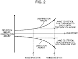
Fig. 2 is a graph showing a relationship between a load weight, a deflection amount, and a compensation amount. -
Fig. 3 is a timing chart illustrating a relationship between a hand opening/closing operation, a compensation amount, and a deviation from a target position in the case where the hand opening/closing operation is normally performed. -
Fig. 4 is a timing chart illustrating a relationship between the hand opening/closing operation, the compensation amount, and the deviation from the target position in the case where a delay has occurred in the hand opening/closing operation. -
Fig. 5 is a perspective view for explaining a positional relationship between a hand, a workpiece, and a workbench when a delay has occurred in the hand opening/closing operation. -
Fig. 6 is a timing chart illustrating a relationship between the hand opening/closing operation, the compensation amount, and the deviation from the target position in the case where a delay command is executed after a hand opening command is executed. -
Fig. 7 is a perspective view for explaining a positional relationship between the hand, the workpiece, and the workbench in the case where the delay command is executed after the hand opening command is executed. -
Fig. 8 is a timing chart illustrating a relationship between the hand opening/closing operation, the compensation amount, and the deviation from the target position in the case where a control method according to the present exemplary embodiment is applied. -
Fig. 9 is a timing chart illustrating a relationship between the compensation amount, a compensation amount change rate, and a compensation amount change acceleration in the case where a control method according to a first modification is applied. -
Fig. 10 is a timing chart illustrating a relationship between the hand opening/closing operation, the compensation amount, and the deviation from the target position in the case where a control method according to a second modification is applied. - An exemplary embodiment of the present disclosure is described below with reference to the drawings. Note that the following description of the preferred exemplary embodiment is merely exemplary in nature, and is not intended to limit the present disclosure, its application, or its use.
- As illustrated in
Fig. 1 ,robot 1 includes six-axis articulatedrobot arm 10 andcontroller 20 that controls the operation ofrobot arm 10.Robot 1 transfers workpiece W to and fromworkbench 5. -
Robot arm 10 includesbase 11,shoulder 12,lower arm 13, firstupper arm 14, secondupper arm 15,wrist 16, and attachingpart 17. -
Shoulder 12 is supported onbase 11 so as to be turnable in the horizontal direction about first joint J1.Lower arm 13 is supported onshoulder 12 so as to be turnable in the vertical direction about second joint J2. - First
upper arm 14 is supported onlower arm 13 so as to be turnable in the vertical direction about third joint J3. Secondupper arm 15 is supported on the tip of firstupper arm 14 so as to be torsionally rotatable about fourth joint J4. -
Wrist 16 is supported on secondupper arm 15 so as to be turnable in the vertical direction about fifth joint J5. Attachingpart 17 is supported onwrist 16 so as to be torsionally rotatable about sixth joint J6. Hand 18 (gripping part) that grips workpiece W is attached to attachingpart 17. - An unillustrated actuator is built in each of first joint J1 to sixth joint J6.
Controller 20 controls driving of the actuators of first joint J1 to sixth joint J6 based on an operation program input in advance by teaching or the like so that first joint J1 to sixth joint J6 reach target positions (command angles), respectively. -
Robot arm 10 moves workpiece W gripped byhand 18 to a first teaching point ofworkbench 5, openshand 18 at the first teaching point, and brings workpiece W into the non-gripping state. Thereafter,robot arm 10 moveshand 18 toward a second teaching point positioned away from the first teaching point in the non-gripping state of workpiece W. - Incidentally, in articulated
robot 1 as described above,robot arm 10 is deflected and deformed in the direction of gravity by the weight ofrobot arm 10, the weight ofhand 18 at the tip ofrobot arm 10, and the load weight of workpiece W. - Specifically, unillustrated speed reducers and bearings are provided in first joint J1 to sixth joint J6, and
robot arm 10 is deflected by elastic deformation of the speed reducers and the bearings, and the tip ofhand 18 is deviated from the target position. - Therefore, in
robot arm 10 according to the present exemplary embodiment, this deflection is eliminated in consideration of the static elastic deflection generated in second joint J2 and third joint J3 turnable in the gravity direction. - More specifically, the gravitational torque acts on second joint J2 and third joint J3 in the clockwise direction in
Fig. 1 , and the deflection occurs in the turning direction of the rotation shaft. Therefore, second joint J2 and third joint J3 are turned in the counterclockwise direction inFig. 1 to cancel the deflection generated at second joint J2 and third joint J3, thereby compensating for the positional deviation generated at the tip ofhand 18. - As illustrated in
Fig. 2 , a deflection amount ofrobot arm 10 increases in the downward direction as the load weight of workpiece W increases. A compensation amount ofrobot arm 10 increases in the upward direction in order to cancel the deflection amount as the load weight of workpiece W increases. - A fluctuation range of
hand 18 is larger in the state ofhand 18 being closed (in the gripping state of workpiece W) than in the state ofhand 18 being opened (in the non-gripping state of the workpiece W), and a variation range of the compensation amount is also larger. - When workpiece W is transferred to the
workbench 5 after workpiece W is gripped byhand 18 and the deflection compensation ofrobot arm 10 is performed, the tip ofhand 18 is deviated by the amount of the weight of workpiece W which is no longer applied tohand 18. - Therefore, when workpiece W is in the non-gripping state, second joint J2 and third joint J3 need to be turned in order to eliminate the positional deviation of the tip of
hand 18. - As shown in
Fig. 3 , in a state ofhand 18 being closed, the deflection compensation ofrobot arm 10 is performed based on a first compensation amount. When an opening command ofhand 18 is output andhand 18 is opened, the compensation amount is switched to a second compensation amount smaller than the first compensation amount, and the deflection compensation ofrobot arm 10 is performed based on the second compensation amount. - The deflection compensation of
robot arm 10 based on the second compensation amount is performed by turning second joint J2 and third joint J3 in the clockwise direction inFig. 1 . That is,hand 18 is made to be lowered by the amount thathand 18 has been lifted in order to compensate for the deflection ofrobot arm 10 due to the weight of workpiece W. - Meanwhile, a malfunction possibly occurs if the actual gripping state of workpiece W and the switching timing of the compensation amount of
robot arm 10 are not appropriate. - Specifically, as illustrated in
Fig. 4 , when a delay occurs in the opening operation ofhand 18 at the time of openinghand 18 after workpiece W is placed onworkbench 5, the compensation amount ofrobot arm 10 is switched in the state ofhand 18 still gripping workpiece W. As a result, there is a risk that workpiece W is damaged by being pressed against workbench 5 (seeFig. 5 ). - Therefore, as illustrated in
Fig. 6 , it is conceivable to execute a delay command and wait for a predetermined time after the opening command ofhand 18 is output, and to switch the compensation amount ofrobot arm 10 after the opening operation ofhand 18 is securely performed. - However, if workpiece W is a heavy object and the compensation amount of
robot arm 10 is large, the acceleration ofrobot arm 10 generated based on the change in the compensation amount also becomes large. In this case,robot arm 10 possibly moves by a width equal to or larger than the compensation amount, and there is a risk ofhand 18 coming into contact with workbench 5 (seeFig. 7 ). - Therefore, in the present exemplary embodiment, when workpiece W is brought from the gripping state to the non-gripping state, the compensation amount of
robot arm 10 can be gently varied, and unintended movement ofrobot arm 10 can be suppressed. - Specifically, as illustrated in
Fig. 8 , workpiece W held byhand 18 is moved to the first teaching point ofworkbench 5. In the state ofhand 18 being closed, the deflection compensation ofrobot arm 10 is performed based on the first compensation amount. - The delay command is executed after the opening command of
hand 18 is output at the first teaching point to cause the operation to wait for a predetermined time so that the opening operation ofhand 18 is securely performed. - Thereafter, in the non-gripping state of workpiece W, second joint J2 and third joint J3 are operated while the compensation amount is changed to gradually decrease, while
hand 18 is moved from the first teaching point to the second teaching point. - Specifically, the compensation amount includes the first compensation amount in the gripping state of workpiece W, the second compensation amount in the non-gripping state of workpiece W, and a third compensation amount continuously changing between the first compensation amount and the second compensation amount. The third compensation amount linearly changes from the first compensation amount to the second compensation amount.
- After
hand 18 starts to move from the first teaching point toward the second teaching point in the non-gripping state of workpiece W, the deflection compensation ofrobot arm 10 is performed based on the third compensation amount untilhand 18 arrives at the second teaching point. - As a result, when workpiece W is brought from the gripping state to the non-gripping state, the compensation amount of
robot arm 10 can be gently varied, and unintended movement ofrobot arm 10 can be suppressed. - As illustrated in
Fig. 9 , in a first modification, the compensation amount whilehand 18 is moved from the first teaching point to the second teaching point is changed by a change amount different from that in the exemplary embodiment. - Specifically, the compensation amount includes the first compensation amount in the gripping state of workpiece W, the second compensation amount in the non-gripping state of workpiece W, and a third compensation amount continuously changing between the first compensation amount and the second compensation amount.
- The third compensation amount linearly changes from the first compensation amount to the second compensation amount. Also, in the third compensation amount, a boundary position between the first compensation amount and the third compensation amount and a boundary position between the third compensation amount and the second compensation amount change in a curved shape.
- After
hand 18 starts to move from the first teaching point toward the second teaching point in the non-gripping state of workpiece W, the deflection compensation ofrobot arm 10 is performed based on the third compensation amount untilhand 18 arrives at the second teaching point. - As a result, when workpiece W is brought from the gripping state to the non-gripping state, the compensation amount of
robot arm 10 can be more gently varied, and unintended movement ofrobot arm 10 can be suppressed. - Here, the acceleration of
robot arm 10 generated based on the change in the third compensation amount is set within a range of allowable acceleration ofrobot arm 10. Specifically, in the case of the compensation amount being 0.1° and the maximum allowable acceleration is 300°/s2, the changing time of the compensation amount is set to 0.4 seconds. - Assuming that the entire changing time (0.4 seconds) of the compensation amount is 100%, the compensation amount is changed such that a curved section at the boundary position between the first compensation amount and the third compensation amount is 30%, a straight line section of the third compensation amount is 40%, and a curved section at the boundary position between the third compensation amount and the second compensation amount is 30%.
- As a result, the compensation amount of the
robot arm 10 can be more gently varied, and therobot arm 10 can be suppressed from operating with a width exceeding the compensation amount. - As illustrated in
Fig. 10 , in a second modification, the time from when workpiece W is brought into the non-gripping state to whenhand 18 starts to move from the first teaching point to the second teaching point is shorter than that in the exemplary embodiment. - In this case where the time until
hand 18 starts to move from the first teaching point to the second teaching point is shorter than a predetermined time, second joint J2 and third joint J3 are operated based on a fourth compensation amount that changes more gently than the third compensation amount. - As a result, when workpiece W is brought from the gripping state to the non-gripping state, the compensation amount of
robot arm 10 can be more gently varied, and unintended movement ofrobot arm 10 can be suppressed. - In the case where the distance between
hand 18 and the first teaching point is shorter than a predetermined distance, there is a risk thathand 18 collides withworkbench 5 whenhand 18 is rapidly moved. Therefore, similarly in the case of the distance betweenhand 18 and the first teaching point being short, second joint J2 and third joint J3 are preferably operated based on the fourth compensation amount that changes more gently than the third compensation amount (seeFig. 10 ). - As described above, the present disclosure is extremely useful and has high industrial applicability by the fact of being able to exhibit a highly practical effect of suppressing the malfunction that occurs when the deflection of the arm is compensated after the workpiece is brought into the non-gripping state.
-
- 1
- robot
- 10
- robot arm
- 18
- hand (gripping part)
- J1
- first joint
- J2
- second joint
- J3
- third joint
- J4
- fourth joint
- J5
- fifth joint
- J6
- sixth joint
- W
- workpiece
Claims (6)
- A robot control method configured to operate an arm of a robot having a plurality of joints based on a predetermined operation program, the robot control method comprising:compensating deflection generated in an arm by operating a joint based on a predetermined compensation amount, the deflection being generated by the arm gripping a workpiece with a gripping part of the arm;moving the workpiece to a first teaching point;opening the gripping part at the first teaching point to bring the workpiece into a non-gripping state; andoperating the joint while the compensation amount is changed to gradually decrease in the non-gripping state of the workpiece and while the gripping part is moved from the first teaching point to the second teaching point.
- The robot control method according to Claim 1, whereinthe compensation amount includes a first compensation amount in a gripping state of the workpiece, a second compensation amount in the non-gripping state of the workpiece, and a third compensation amount continuously changing between the first compensation amount and the second compensation amount, andthe third compensation amount changes linearly from the first compensation amount toward the second compensation amount.
- The robot control method according to Claim 2, wherein
the third compensation amount changes in a curved shape at a boundary position between the first compensation amount and the third compensation amount and at a boundary position between the third compensation amount and the second compensation amount. - The robot control method according to Claim 2 or 3, wherein
the joint is operated based on a fourth compensation amount that changes more gently than the third compensation amount, in a case where a time from when the workpiece is brought into the non-gripping state to when the gripping part starts to move from the first teaching point to the second teaching point is shorter than a predetermined time. - The robot control method according to any one of Claims 2 to 4, wherein
the joint is operated based on a fourth compensation amount that changes more gently than the third compensation amount, in a case where a distance between the gripping part and the first teaching point is shorter than a predetermined distance. - The robot control method according to any one of Claims 1 to 5, wherein
the arm has an acceleration within a range of allowable acceleration of the arm, the acceleration being generated based on a change in the compensation amount.
Priority Applications (1)
| Application Number | Priority Date | Filing Date | Title |
|---|---|---|---|
| EP25221090.1A EP4681890A1 (en) | 2019-11-05 | 2020-10-22 | Robot control method |
Applications Claiming Priority (2)
| Application Number | Priority Date | Filing Date | Title |
|---|---|---|---|
| JP2019200787 | 2019-11-05 | ||
| PCT/JP2020/039672 WO2021090693A1 (en) | 2019-11-05 | 2020-10-22 | Robot control method |
Related Child Applications (2)
| Application Number | Title | Priority Date | Filing Date |
|---|---|---|---|
| EP25221090.1A Division EP4681890A1 (en) | 2019-11-05 | 2020-10-22 | Robot control method |
| EP25221090.1A Division-Into EP4681890A1 (en) | 2019-11-05 | 2020-10-22 | Robot control method |
Publications (3)
| Publication Number | Publication Date |
|---|---|
| EP4056330A1 true EP4056330A1 (en) | 2022-09-14 |
| EP4056330A4 EP4056330A4 (en) | 2022-12-14 |
| EP4056330B1 EP4056330B1 (en) | 2026-01-21 |
Family
ID=75848354
Family Applications (2)
| Application Number | Title | Priority Date | Filing Date |
|---|---|---|---|
| EP20885590.8A Active EP4056330B1 (en) | 2019-11-05 | 2020-10-22 | Robot control method |
| EP25221090.1A Pending EP4681890A1 (en) | 2019-11-05 | 2020-10-22 | Robot control method |
Family Applications After (1)
| Application Number | Title | Priority Date | Filing Date |
|---|---|---|---|
| EP25221090.1A Pending EP4681890A1 (en) | 2019-11-05 | 2020-10-22 | Robot control method |
Country Status (4)
| Country | Link |
|---|---|
| US (1) | US12280504B2 (en) |
| EP (2) | EP4056330B1 (en) |
| JP (1) | JP7133757B2 (en) |
| WO (1) | WO2021090693A1 (en) |
Families Citing this family (1)
| Publication number | Priority date | Publication date | Assignee | Title |
|---|---|---|---|---|
| CN115488894B (en) * | 2022-10-19 | 2025-04-15 | 杭州柳叶刀机器人有限公司 | Robot follow-up control method, device, control terminal and storage medium |
Family Cites Families (30)
| Publication number | Priority date | Publication date | Assignee | Title |
|---|---|---|---|---|
| JPH0788789B2 (en) | 1986-01-17 | 1995-09-27 | マツダ株式会社 | Air-fuel ratio controller for engine |
| US4919586A (en) * | 1988-05-25 | 1990-04-24 | Grasp, Inc. | Mechanical closed loop robotic arm end effector positioning system |
| JPH06320450A (en) * | 1993-05-11 | 1994-11-22 | Mitsubishi Electric Corp | Industrial robot speed controller |
| JP3101134B2 (en) | 1993-09-20 | 2000-10-23 | 豊田工機株式会社 | Robot controller |
| JP3820422B2 (en) | 1998-12-08 | 2006-09-13 | 株式会社東芝 | Manipulator teaching / reproducing apparatus and teaching / reproducing method thereof |
| TW200502070A (en) * | 2003-07-04 | 2005-01-16 | Rorze Corp | Carrying apparatus and carrying control method for sheet-like objects |
| US20060216137A1 (en) * | 2004-07-02 | 2006-09-28 | Katsunori Sakata | Carrying apparatus and carrying control method for sheet-like substrate |
| US9110456B2 (en) * | 2004-09-08 | 2015-08-18 | Abb Research Ltd. | Robotic machining with a flexible manipulator |
| US20060060573A1 (en) * | 2004-09-15 | 2006-03-23 | Wolfgang Becker | Process for preparing a workpiece to be worked with a laser beam, and device for carrying out the process |
| JP2008514504A (en) * | 2004-09-30 | 2008-05-08 | アーベーベー アーエス | Door opening and closing mechanism used for industrial robots |
| KR101198179B1 (en) * | 2005-01-17 | 2012-11-16 | 삼성전자주식회사 | Method for compensation static deflection of handling robot and apparatus thereof |
| AT504257B1 (en) * | 2006-09-18 | 2008-06-15 | Univ Linz | DEVICE FOR CONTROLLING A ROBOT ARM |
| JP2008105125A (en) | 2006-10-25 | 2008-05-08 | Nachi Fujikoshi Corp | Deflection correction device for transfer robot system |
| US7946800B2 (en) * | 2007-04-06 | 2011-05-24 | Brooks Automation, Inc. | Substrate transport apparatus with multiple independently movable articulated arms |
| US8752449B2 (en) * | 2007-05-08 | 2014-06-17 | Brooks Automation, Inc. | Substrate transport apparatus with multiple movable arms utilizing a mechanical switch mechanism |
| WO2010083244A2 (en) * | 2009-01-13 | 2010-07-22 | Camotion, Inc. | Machine tools with non-rigid robot device using inertial stiffening |
| JP2010274396A (en) * | 2009-06-01 | 2010-12-09 | Kawasaki Heavy Ind Ltd | Position shift correction method and position shift correction program in automatic work system |
| WO2013069291A1 (en) | 2011-11-10 | 2013-05-16 | パナソニック株式会社 | Robot, and control device, control method and control program for robot |
| JP5921248B2 (en) * | 2012-02-16 | 2016-05-24 | キヤノン株式会社 | ROBOT CONTROL DEVICE, ROBOT, PROGRAM THEREOF, AND ITS CONTROL METHOD |
| US10037017B2 (en) * | 2012-04-18 | 2018-07-31 | Renishaw Plc | Method of measurement on a machine tool and corresponding machine tool apparatus |
| DE102012012988A1 (en) * | 2012-06-29 | 2014-04-17 | Liebherr-Verzahntechnik Gmbh | Device for the automated handling of workpieces |
| DE102012013030A1 (en) * | 2012-06-29 | 2014-04-24 | Liebherr-Verzahntechnik Gmbh | Device for the automatic removal of workpieces arranged in a container |
| WO2014041469A1 (en) * | 2012-09-13 | 2014-03-20 | University Of The Free State | Mammographic tomography test phantom |
| GB201419182D0 (en) * | 2014-10-28 | 2014-12-10 | Nlink As | Mobile robotic drilling apparatus and method for drilling ceillings and walls |
| JP6360027B2 (en) * | 2014-11-14 | 2018-07-18 | フェルロボティクス コンプライアント ロボット テクノロジー ゲーエムベーハーFerrobotics Compliant Robot Technology GmbH | Robot roller hemming apparatus and method |
| JP7061119B2 (en) * | 2016-07-15 | 2022-04-27 | ファストブリック・アイピー・プロプライエタリー・リミテッド | Brick / block laying machine built into the vehicle |
| JP6707485B2 (en) * | 2017-03-22 | 2020-06-10 | 株式会社東芝 | Object handling device and calibration method thereof |
| EP3653347B1 (en) * | 2017-07-11 | 2024-09-11 | Panasonic Intellectual Property Management Co., Ltd. | Robot control device |
| AU2019336263A1 (en) * | 2018-09-04 | 2021-04-08 | Fastbrick Ip Pty Ltd | Vision system for a robotic machine |
| CN113905853B (en) * | 2019-06-04 | 2024-03-08 | 松下知识产权经营株式会社 | Robot control method |
-
2020
- 2020-10-22 EP EP20885590.8A patent/EP4056330B1/en active Active
- 2020-10-22 JP JP2021554878A patent/JP7133757B2/en active Active
- 2020-10-22 WO PCT/JP2020/039672 patent/WO2021090693A1/en not_active Ceased
- 2020-10-22 EP EP25221090.1A patent/EP4681890A1/en active Pending
-
2022
- 2022-02-18 US US17/674,902 patent/US12280504B2/en active Active
Also Published As
| Publication number | Publication date |
|---|---|
| US20220168891A1 (en) | 2022-06-02 |
| WO2021090693A1 (en) | 2021-05-14 |
| JP7133757B2 (en) | 2022-09-09 |
| EP4681890A1 (en) | 2026-01-21 |
| EP4056330A4 (en) | 2022-12-14 |
| JPWO2021090693A1 (en) | 2021-05-14 |
| US12280504B2 (en) | 2025-04-22 |
| EP4056330B1 (en) | 2026-01-21 |
Similar Documents
| Publication | Publication Date | Title |
|---|---|---|
| JP5897644B2 (en) | Robot control device | |
| EP3342558B1 (en) | Industrial robot and operation method thereof | |
| US9616564B2 (en) | Event-based redundancy angle configuration for articulated-arm robots | |
| US10864632B2 (en) | Direct teaching method of robot | |
| US8249746B2 (en) | Method and device to regulate an automated manipulator | |
| CN107363861B (en) | Robot, control device, and robot system | |
| DK2492062T3 (en) | industrial Robot | |
| EP3351355B1 (en) | Device and method for positioning processing tool | |
| JPWO2012077335A1 (en) | ROBOT CONTROL DEVICE AND CONTROL METHOD, ROBOT, AND CONTROL PROGRAM | |
| WO2018212265A1 (en) | Robot system and robot system control method | |
| WO2015115887A1 (en) | Robot comprising series-arranged delta assemblies | |
| JP2010231575A (en) | Device and method for instruction of off-line of robot, and robot system | |
| US12280504B2 (en) | Robot control method | |
| CN112041125B (en) | Robot control method | |
| US9827673B2 (en) | Robot controller inhibiting shaking of tool tip in robot equipped with travel axis | |
| JP6934640B2 (en) | Robot control method | |
| CN110871449B (en) | Mechanical arm | |
| CN110139731B (en) | Calibration of a model of a process robot and operation of a process robot | |
| JP5492168B2 (en) | Grip mechanism | |
| Stückler et al. | Compliant task-space control with back-drivable servo actuators | |
| CN113905853B (en) | Robot control method | |
| Gungor et al. | Online estimation and compensation of friction in industrial cable robot manipulation | |
| WO2022124039A1 (en) | Robot and teaching method | |
| Do et al. | A manipulator with counterbalancing mechanism for safety in human-robot collaboration | |
| JPH07205072A (en) | Cooperative control device for multiple robots |
Legal Events
| Date | Code | Title | Description |
|---|---|---|---|
| STAA | Information on the status of an ep patent application or granted ep patent |
Free format text: STATUS: THE INTERNATIONAL PUBLICATION HAS BEEN MADE |
|
| PUAI | Public reference made under article 153(3) epc to a published international application that has entered the european phase |
Free format text: ORIGINAL CODE: 0009012 |
|
| STAA | Information on the status of an ep patent application or granted ep patent |
Free format text: STATUS: REQUEST FOR EXAMINATION WAS MADE |
|
| 17P | Request for examination filed |
Effective date: 20220210 |
|
| AK | Designated contracting states |
Kind code of ref document: A1 Designated state(s): AL AT BE BG CH CY CZ DE DK EE ES FI FR GB GR HR HU IE IS IT LI LT LU LV MC MK MT NL NO PL PT RO RS SE SI SK SM TR |
|
| REG | Reference to a national code |
Ref country code: DE Ref legal event code: R079 Free format text: PREVIOUS MAIN CLASS: B25J0009100000 Ipc: B25J0009160000 Ref country code: DE Ref legal event code: R079 Ref document number: 602020065669 Country of ref document: DE Free format text: PREVIOUS MAIN CLASS: B25J0009100000 Ipc: B25J0009160000 |
|
| A4 | Supplementary search report drawn up and despatched |
Effective date: 20221116 |
|
| RIC1 | Information provided on ipc code assigned before grant |
Ipc: B25J 9/16 20060101AFI20221110BHEP |
|
| DAV | Request for validation of the european patent (deleted) | ||
| DAX | Request for extension of the european patent (deleted) | ||
| STAA | Information on the status of an ep patent application or granted ep patent |
Free format text: STATUS: EXAMINATION IS IN PROGRESS |
|
| 17Q | First examination report despatched |
Effective date: 20241030 |
|
| GRAP | Despatch of communication of intention to grant a patent |
Free format text: ORIGINAL CODE: EPIDOSNIGR1 |
|
| STAA | Information on the status of an ep patent application or granted ep patent |
Free format text: STATUS: GRANT OF PATENT IS INTENDED |
|
| INTG | Intention to grant announced |
Effective date: 20250902 |
|
| GRAS | Grant fee paid |
Free format text: ORIGINAL CODE: EPIDOSNIGR3 |
|
| GRAA | (expected) grant |
Free format text: ORIGINAL CODE: 0009210 |
|
| STAA | Information on the status of an ep patent application or granted ep patent |
Free format text: STATUS: THE PATENT HAS BEEN GRANTED |
|
| AK | Designated contracting states |
Kind code of ref document: B1 Designated state(s): AL AT BE BG CH CY CZ DE DK EE ES FI FR GB GR HR HU IE IS IT LI LT LU LV MC MK MT NL NO PL PT RO RS SE SI SK SM TR |
|
| REG | Reference to a national code |
Ref country code: CH Ref legal event code: F10 Free format text: ST27 STATUS EVENT CODE: U-0-0-F10-F00 (AS PROVIDED BY THE NATIONAL OFFICE) Effective date: 20260121 |
|
| REG | Reference to a national code |
Ref country code: DE Ref legal event code: R096 Ref document number: 602020065669 Country of ref document: DE |
|
| REG | Reference to a national code |
Ref country code: IE Ref legal event code: FG4D |