EP4056295B1 - Method of making an interaxle differential unit - Google Patents
Method of making an interaxle differential unit Download PDFInfo
- Publication number
- EP4056295B1 EP4056295B1 EP22159901.2A EP22159901A EP4056295B1 EP 4056295 B1 EP4056295 B1 EP 4056295B1 EP 22159901 A EP22159901 A EP 22159901A EP 4056295 B1 EP4056295 B1 EP 4056295B1
- Authority
- EP
- European Patent Office
- Prior art keywords
- annular case
- workpiece
- gear
- opening
- end surface
- Prior art date
- Legal status (The legal status is an assumption and is not a legal conclusion. Google has not performed a legal analysis and makes no representation as to the accuracy of the status listed.)
- Active
Links
Images


Classifications
-
- F—MECHANICAL ENGINEERING; LIGHTING; HEATING; WEAPONS; BLASTING
- F16—ENGINEERING ELEMENTS AND UNITS; GENERAL MEASURES FOR PRODUCING AND MAINTAINING EFFECTIVE FUNCTIONING OF MACHINES OR INSTALLATIONS; THERMAL INSULATION IN GENERAL
- F16H—GEARING
- F16H48/00—Differential gearings
- F16H48/38—Constructional details
-
- B—PERFORMING OPERATIONS; TRANSPORTING
- B21—MECHANICAL METAL-WORKING WITHOUT ESSENTIALLY REMOVING MATERIAL; PUNCHING METAL
- B21H—MAKING PARTICULAR METAL OBJECTS BY ROLLING, e.g. SCREWS, WHEELS, RINGS, BARRELS, BALLS
- B21H1/00—Making articles shaped as bodies of revolution
- B21H1/06—Making articles shaped as bodies of revolution rings of restricted axial length
-
- B—PERFORMING OPERATIONS; TRANSPORTING
- B21—MECHANICAL METAL-WORKING WITHOUT ESSENTIALLY REMOVING MATERIAL; PUNCHING METAL
- B21K—MAKING FORGED OR PRESSED METAL PRODUCTS, e.g. HORSE-SHOES, RIVETS, BOLTS OR WHEELS
- B21K1/00—Making machine elements
- B21K1/76—Making machine elements elements not mentioned in one of the preceding groups
- B21K1/761—Making machine elements elements not mentioned in one of the preceding groups rings
-
- B—PERFORMING OPERATIONS; TRANSPORTING
- B21—MECHANICAL METAL-WORKING WITHOUT ESSENTIALLY REMOVING MATERIAL; PUNCHING METAL
- B21J—FORGING; HAMMERING; PRESSING METAL; RIVETING; FORGE FURNACES
- B21J1/00—Preparing metal stock or similar ancillary operations prior, during or post forging, e.g. heating or cooling
- B21J1/04—Shaping in the rough solely by forging or pressing
-
- B—PERFORMING OPERATIONS; TRANSPORTING
- B21—MECHANICAL METAL-WORKING WITHOUT ESSENTIALLY REMOVING MATERIAL; PUNCHING METAL
- B21J—FORGING; HAMMERING; PRESSING METAL; RIVETING; FORGE FURNACES
- B21J5/00—Methods for forging, hammering, or pressing; Special equipment or accessories therefor
- B21J5/06—Methods for forging, hammering, or pressing; Special equipment or accessories therefor for performing particular operations
- B21J5/10—Piercing billets
-
- B—PERFORMING OPERATIONS; TRANSPORTING
- B21—MECHANICAL METAL-WORKING WITHOUT ESSENTIALLY REMOVING MATERIAL; PUNCHING METAL
- B21K—MAKING FORGED OR PRESSED METAL PRODUCTS, e.g. HORSE-SHOES, RIVETS, BOLTS OR WHEELS
- B21K1/00—Making machine elements
- B21K1/26—Making machine elements housings or supporting parts, e.g. axle housings, engine mountings
-
- B—PERFORMING OPERATIONS; TRANSPORTING
- B23—MACHINE TOOLS; METAL-WORKING NOT OTHERWISE PROVIDED FOR
- B23P—METAL-WORKING NOT OTHERWISE PROVIDED FOR; COMBINED OPERATIONS; UNIVERSAL MACHINE TOOLS
- B23P15/00—Making specific metal objects by operations not covered by a single other subclass or a group in this subclass
- B23P15/14—Making specific metal objects by operations not covered by a single other subclass or a group in this subclass gear parts, e.g. gear wheels
-
- B—PERFORMING OPERATIONS; TRANSPORTING
- B60—VEHICLES IN GENERAL
- B60K—ARRANGEMENT OR MOUNTING OF PROPULSION UNITS OR OF TRANSMISSIONS IN VEHICLES; ARRANGEMENT OR MOUNTING OF PLURAL DIVERSE PRIME-MOVERS IN VEHICLES; AUXILIARY DRIVES FOR VEHICLES; INSTRUMENTATION OR DASHBOARDS FOR VEHICLES; ARRANGEMENTS IN CONNECTION WITH COOLING, AIR INTAKE, GAS EXHAUST OR FUEL SUPPLY OF PROPULSION UNITS IN VEHICLES
- B60K1/00—Arrangement or mounting of electrical propulsion units
-
- B—PERFORMING OPERATIONS; TRANSPORTING
- B60—VEHICLES IN GENERAL
- B60K—ARRANGEMENT OR MOUNTING OF PROPULSION UNITS OR OF TRANSMISSIONS IN VEHICLES; ARRANGEMENT OR MOUNTING OF PLURAL DIVERSE PRIME-MOVERS IN VEHICLES; AUXILIARY DRIVES FOR VEHICLES; INSTRUMENTATION OR DASHBOARDS FOR VEHICLES; ARRANGEMENTS IN CONNECTION WITH COOLING, AIR INTAKE, GAS EXHAUST OR FUEL SUPPLY OF PROPULSION UNITS IN VEHICLES
- B60K17/00—Arrangement or mounting of transmissions in vehicles
- B60K17/04—Arrangement or mounting of transmissions in vehicles characterised by arrangement, location or kind of gearing
- B60K17/16—Arrangement or mounting of transmissions in vehicles characterised by arrangement, location or kind of gearing of differential gearing
- B60K17/165—Arrangement or mounting of transmissions in vehicles characterised by arrangement, location or kind of gearing of differential gearing provided between independent half axles
-
- C—CHEMISTRY; METALLURGY
- C21—METALLURGY OF IRON
- C21D—MODIFYING THE PHYSICAL STRUCTURE OF FERROUS METALS; GENERAL DEVICES FOR HEAT TREATMENT OF FERROUS OR NON-FERROUS METALS OR ALLOYS; MAKING METAL MALLEABLE, e.g. BY DECARBURISATION OR TEMPERING
- C21D1/00—General methods or devices for heat treatment, e.g. annealing, hardening, quenching or tempering
- C21D1/18—Hardening; Quenching with or without subsequent tempering
- C21D1/19—Hardening; Quenching with or without subsequent tempering by interrupted quenching
- C21D1/22—Martempering
-
- C—CHEMISTRY; METALLURGY
- C21—METALLURGY OF IRON
- C21D—MODIFYING THE PHYSICAL STRUCTURE OF FERROUS METALS; GENERAL DEVICES FOR HEAT TREATMENT OF FERROUS OR NON-FERROUS METALS OR ALLOYS; MAKING METAL MALLEABLE, e.g. BY DECARBURISATION OR TEMPERING
- C21D1/00—General methods or devices for heat treatment, e.g. annealing, hardening, quenching or tempering
- C21D1/74—Methods of treatment in inert gas, controlled atmosphere, vacuum or pulverulent material
-
- C—CHEMISTRY; METALLURGY
- C21—METALLURGY OF IRON
- C21D—MODIFYING THE PHYSICAL STRUCTURE OF FERROUS METALS; GENERAL DEVICES FOR HEAT TREATMENT OF FERROUS OR NON-FERROUS METALS OR ALLOYS; MAKING METAL MALLEABLE, e.g. BY DECARBURISATION OR TEMPERING
- C21D8/00—Modifying the physical properties of ferrous metals or ferrous alloys by deformation combined with, or followed by, heat treatment
-
- C—CHEMISTRY; METALLURGY
- C21—METALLURGY OF IRON
- C21D—MODIFYING THE PHYSICAL STRUCTURE OF FERROUS METALS; GENERAL DEVICES FOR HEAT TREATMENT OF FERROUS OR NON-FERROUS METALS OR ALLOYS; MAKING METAL MALLEABLE, e.g. BY DECARBURISATION OR TEMPERING
- C21D9/00—Heat treatment, e.g. annealing, hardening, quenching or tempering, adapted for particular articles; Furnaces therefor
- C21D9/32—Heat treatment, e.g. annealing, hardening, quenching or tempering, adapted for particular articles; Furnaces therefor for gear wheels, worm wheels, or the like
-
- F—MECHANICAL ENGINEERING; LIGHTING; HEATING; WEAPONS; BLASTING
- F16—ENGINEERING ELEMENTS AND UNITS; GENERAL MEASURES FOR PRODUCING AND MAINTAINING EFFECTIVE FUNCTIONING OF MACHINES OR INSTALLATIONS; THERMAL INSULATION IN GENERAL
- F16H—GEARING
- F16H57/00—General details of gearing
- F16H57/02—Gearboxes; Mounting gearing therein
- F16H57/032—Gearboxes; Mounting gearing therein characterised by the materials used
-
- F—MECHANICAL ENGINEERING; LIGHTING; HEATING; WEAPONS; BLASTING
- F16—ENGINEERING ELEMENTS AND UNITS; GENERAL MEASURES FOR PRODUCING AND MAINTAINING EFFECTIVE FUNCTIONING OF MACHINES OR INSTALLATIONS; THERMAL INSULATION IN GENERAL
- F16H—GEARING
- F16H57/00—General details of gearing
- F16H57/02—Gearboxes; Mounting gearing therein
- F16H57/037—Gearboxes for accommodating differential gearings
-
- B—PERFORMING OPERATIONS; TRANSPORTING
- B60—VEHICLES IN GENERAL
- B60K—ARRANGEMENT OR MOUNTING OF PROPULSION UNITS OR OF TRANSMISSIONS IN VEHICLES; ARRANGEMENT OR MOUNTING OF PLURAL DIVERSE PRIME-MOVERS IN VEHICLES; AUXILIARY DRIVES FOR VEHICLES; INSTRUMENTATION OR DASHBOARDS FOR VEHICLES; ARRANGEMENTS IN CONNECTION WITH COOLING, AIR INTAKE, GAS EXHAUST OR FUEL SUPPLY OF PROPULSION UNITS IN VEHICLES
- B60K1/00—Arrangement or mounting of electrical propulsion units
- B60K2001/001—Arrangement or mounting of electrical propulsion units one motor mounted on a propulsion axle for rotating right and left wheels of this axle
-
- C—CHEMISTRY; METALLURGY
- C21—METALLURGY OF IRON
- C21D—MODIFYING THE PHYSICAL STRUCTURE OF FERROUS METALS; GENERAL DEVICES FOR HEAT TREATMENT OF FERROUS OR NON-FERROUS METALS OR ALLOYS; MAKING METAL MALLEABLE, e.g. BY DECARBURISATION OR TEMPERING
- C21D6/00—Heat treatment of ferrous alloys
- C21D6/004—Heat treatment of ferrous alloys containing Cr and Ni
-
- C—CHEMISTRY; METALLURGY
- C21—METALLURGY OF IRON
- C21D—MODIFYING THE PHYSICAL STRUCTURE OF FERROUS METALS; GENERAL DEVICES FOR HEAT TREATMENT OF FERROUS OR NON-FERROUS METALS OR ALLOYS; MAKING METAL MALLEABLE, e.g. BY DECARBURISATION OR TEMPERING
- C21D6/00—Heat treatment of ferrous alloys
- C21D6/005—Heat treatment of ferrous alloys containing Mn
-
- C—CHEMISTRY; METALLURGY
- C21—METALLURGY OF IRON
- C21D—MODIFYING THE PHYSICAL STRUCTURE OF FERROUS METALS; GENERAL DEVICES FOR HEAT TREATMENT OF FERROUS OR NON-FERROUS METALS OR ALLOYS; MAKING METAL MALLEABLE, e.g. BY DECARBURISATION OR TEMPERING
- C21D6/00—Heat treatment of ferrous alloys
- C21D6/008—Heat treatment of ferrous alloys containing Si
-
- F—MECHANICAL ENGINEERING; LIGHTING; HEATING; WEAPONS; BLASTING
- F16—ENGINEERING ELEMENTS AND UNITS; GENERAL MEASURES FOR PRODUCING AND MAINTAINING EFFECTIVE FUNCTIONING OF MACHINES OR INSTALLATIONS; THERMAL INSULATION IN GENERAL
- F16H—GEARING
- F16H48/00—Differential gearings
- F16H48/38—Constructional details
- F16H2048/382—Methods for manufacturing differential gearings
-
- F—MECHANICAL ENGINEERING; LIGHTING; HEATING; WEAPONS; BLASTING
- F16—ENGINEERING ELEMENTS AND UNITS; GENERAL MEASURES FOR PRODUCING AND MAINTAINING EFFECTIVE FUNCTIONING OF MACHINES OR INSTALLATIONS; THERMAL INSULATION IN GENERAL
- F16H—GEARING
- F16H48/00—Differential gearings
- F16H48/06—Differential gearings with gears having orbital motion
- F16H48/08—Differential gearings with gears having orbital motion comprising bevel gears
-
- F—MECHANICAL ENGINEERING; LIGHTING; HEATING; WEAPONS; BLASTING
- F16—ENGINEERING ELEMENTS AND UNITS; GENERAL MEASURES FOR PRODUCING AND MAINTAINING EFFECTIVE FUNCTIONING OF MACHINES OR INSTALLATIONS; THERMAL INSULATION IN GENERAL
- F16H—GEARING
- F16H48/00—Differential gearings
- F16H48/20—Arrangements for suppressing or influencing the differential action, e.g. locking devices
- F16H48/24—Arrangements for suppressing or influencing the differential action, e.g. locking devices using positive clutches or brakes
-
- Y—GENERAL TAGGING OF NEW TECHNOLOGICAL DEVELOPMENTS; GENERAL TAGGING OF CROSS-SECTIONAL TECHNOLOGIES SPANNING OVER SEVERAL SECTIONS OF THE IPC; TECHNICAL SUBJECTS COVERED BY FORMER USPC CROSS-REFERENCE ART COLLECTIONS [XRACs] AND DIGESTS
- Y10—TECHNICAL SUBJECTS COVERED BY FORMER USPC
- Y10T—TECHNICAL SUBJECTS COVERED BY FORMER US CLASSIFICATION
- Y10T29/00—Metal working
- Y10T29/49—Method of mechanical manufacture
- Y10T29/49462—Gear making
- Y10T29/49464—Assembling of gear into force transmitting device
-
- Y—GENERAL TAGGING OF NEW TECHNOLOGICAL DEVELOPMENTS; GENERAL TAGGING OF CROSS-SECTIONAL TECHNOLOGIES SPANNING OVER SEVERAL SECTIONS OF THE IPC; TECHNICAL SUBJECTS COVERED BY FORMER USPC CROSS-REFERENCE ART COLLECTIONS [XRACs] AND DIGESTS
- Y10—TECHNICAL SUBJECTS COVERED BY FORMER USPC
- Y10T—TECHNICAL SUBJECTS COVERED BY FORMER US CLASSIFICATION
- Y10T29/00—Metal working
- Y10T29/49—Method of mechanical manufacture
- Y10T29/49462—Gear making
- Y10T29/49467—Gear shaping
- Y10T29/49471—Roll forming
Definitions
- This relates to a method of making an interaxle differential unit and an annular case of the interaxle differential unit.
- axle assembly 10 may be provided with a vehicle of any suitable type, such as a truck, bus, farm equipment, military transport or weaponry vehicle, or cargo loading equipment for land, air, or marine vessels.
- the axle assembly 10 may be part of a vehicle drivetrain that may include multiple axle assemblies that may be connected in series.
- the axle assembly 10 may be part of a tandem axle configuration that may include two axle assemblies connected in series.
- the axle assembly 10 that is operatively connected to at least one torque source, such as an electric motor or an internal combustion engine, may be referred to as a first axle assembly.
- the axle assembly that receives propulsion torque from the torque source by way of the first axle assembly may be referred to as a second axle assembly.
- the axle assembly 10 is depicted as being a first axle assembly.
- the axle assembly 10 may provide torque to its associated wheel assemblies and may provide torque to the second axle assembly.
- the axle assembly 10 may include a housing 20, an input yoke 22, an input shaft 24, a first gear 26, a clutch collar 28, a driven gear 30, a drive pinion 32, a differential assembly 34, at least one axle shaft 36, an interaxle differential unit 38, an output shaft 40, an output yoke 42, or combinations thereof. These components are shown to facilitate an abbreviated discussion of the operation of the axle assembly 10.
- the housing 20 may receive various components of the axle assembly 10. In addition, the housing 20 may facilitate mounting of the axle assembly 10 to the vehicle.
- the input yoke 22 may facilitate coupling of the axle assembly 10 to a torque source.
- the input yoke 22 may be operatively connected to the input shaft 24. It is contemplated that the input yoke 22 may be omitted, such as when a torque source like an electric motor is integrated with the axle assembly 10.
- the input shaft 24 may extend along and may be configured to rotate about an axis 50.
- the input shaft 24 may be rotatably supported by one or more bearings that may be disposed on the housing 20.
- the input shaft 24 may be operatively connected to the interaxle differential unit 38.
- the input shaft 24 may include a first spline 60 that may engage the clutch collar 28.
- the first gear 26, which may also be referred to as a drive gear, may be part of an interaxle differential unit gear nest of the interaxle differential unit 38 as will be discussed in more detail below.
- the first gear 26 may be rotatable about the axis 50.
- the first gear 26 may be selectively coupled to the input shaft 24 with the clutch collar 28.
- the first gear 26 may be rotatable about the axis 50 with the input shaft 24 when the clutch collar 28 couples the first gear 26 to the input shaft 24 and the first gear 26 may be rotatable about the axis 50 with respect to the input shaft 24 when the clutch collar 28 does not couple the first gear 26 to the input shaft 24.
- the first gear 26 may have a center bore that may receive the input shaft 24 and optionally a bearing that may rotatably support the first gear 26 on the input shaft 24.
- the first gear 26 may include outer gear teeth 70, face gear teeth 72, and side gear teeth 74.
- the outer gear teeth 70 may engage and may mesh with teeth on the driven gear 30.
- the outer gear teeth 70 may extend away from the axis 50 and may be arranged around an outside diameter of the first gear 26.
- the face gear teeth 72 may include a set of teeth that may be arranged on a side or face of the first gear 26 that may face away from the interaxle differential unit 38 and toward the clutch collar 28.
- the face gear teeth 72 may selectively engage teeth on the clutch collar 28, such as when the clutch collar 28 couples the first gear 26 to the input shaft 24.
- the side gear teeth 74 may be disposed on an opposite side of the first gear 26 from the face gear teeth 72.
- the side gear teeth 74 may be arranged around the axis 50 and that may face toward gears that may be disposed inside the interaxle differential unit 38.
- the clutch collar 28, if provided, may be moveable along the axis 50 to engage or disengage the first gear 26.
- the clutch collar 28 may be generally ring-shaped and may define a clutch collar hole 80, a clutch collar spline 82, a clutch collar face gear 84, and an annular groove 86.
- the clutch collar hole 80 may extend around the axis 50.
- the clutch collar hole 80 may receive the input shaft 24.
- the clutch collar spline 82 may be disposed in the clutch collar hole 80.
- the clutch collar spline 82 may include a plurality of spline teeth that may extend toward the axis 50 and that may mate or mesh with the teeth of the first spline 60 of the input shaft 24.
- the clutch collar 28 may be rotatable about the axis 50 with the input shaft 24 and may be moveable along the axis 50 or moveable in an axial direction with respect to the input shaft 24.
- the clutch collar face gear 84 may include a set of teeth that may be arranged around the axis 50 and that may face toward and extend toward the face gear teeth 72 of the first gear 26.
- the teeth of the clutch collar face gear 84 may selectively engage the teeth of the face gear teeth 72 of the first gear 26.
- the annular groove 86 may receive a linkage, such as a fork, that may operatively connect the clutch collar 28 to an actuator that may position the clutch collar 28 along the axis 50.
- a linkage such as a fork
- the driven gear 30 may be rotatable about a second axis 90.
- the drive pinion 32 may be received in a center bore of the driven gear 30 and the driven gear 30 may be fixedly disposed on the drive pinion 32 or may be couplable to the drive pinion 32 such that the driven gear 30 and the drive pinion 32 may rotate together about the second axis 90.
- the driven gear 30 may include a plurality of teeth that may be generally arranged about an outside diameter of the driven gear 30 and that may mate or mesh with the teeth of the outer gear teeth 70 of the first gear 26. Only a portion of the driven gear 30 disposed above the second axis 90 is shown in Figure 2 .
- the second axis 90 may be disposed substantially parallel to the axis 50.
- substantially parallel as used herein means the same as or very close to parallel and includes features or axes that are within ⁇ 2° of being parallel each other.
- the drive pinion 32 may operatively connect the torque source to the differential assembly 34.
- the drive pinion 32 may be spaced apart from the input shaft 24 and may be configured to rotate about an axis, such as a second axis 90.
- the drive pinion 32 may rotate with the driven gear 30. It is also contemplated that the drive pinion 32 may rotate about the axis 50 in other configurations, such as when the first gear 26 and the driven gear 30 are omitted or when the output shaft 40 extends through the drive pinion 32.
- a gear portion may be disposed at an end of the drive pinion 32.
- the differential assembly 34 may be at least partially received in the housing 20. Only a portion of the differential assembly 34 is shown.
- the differential assembly 34 may be rotatable about an axis, such as a differential axis that may be disposed substantially perpendicular to the second axis 90.
- the term "substantially perpendicular” is used herein to designate features or axes that are the same as or very close to perpendicular and includes features that are within ⁇ 2° of being perpendicular each other.
- the differential assembly 34 may transmit torque to the axle shafts 36 and wheels.
- the differential assembly 34 may be operatively connected to the axle shafts 36 and may permit the axle shafts 36 to rotate at different rotational speeds in a manner known by those skilled in the art.
- the differential assembly 34 may have a ring gear 100 that may have teeth that may mate or mesh with the teeth of the gear portion of the drive pinion 32. Accordingly, the differential assembly 34 may receive torque from the drive pinion 32 via the ring gear 100 and transmit torque to the axle shafts 36.
- the axle shafts 36 may transmit torque from the differential assembly 34 to corresponding wheel hubs and wheels.
- the axle shafts 36 may extend along and may be rotatable about a third axis 102, which may be the differential axis.
- Each axle shaft 36 may have a first end and a second end. The first end may be operatively connected to the differential assembly 34. The second end may be disposed opposite the first end and may be operatively connected to a wheel.
- interaxle differential unit 38 may accommodate or compensate for rotational speed differences between different drive axle assemblies, such as speed differences between the axle assembly 10 and a second axle assembly that is connected in series with the axle assembly 10.
- the interaxle differential unit 38 may be provided in various locations. In Figure 3 , the interaxle differential unit 38 is disposed inside the housing 20 on the input shaft 24; however, it is contemplated that the interaxle differential unit 38 may be provided in other locations, such as closer to the output yoke 42 or with the second axle assembly. It is also contemplated that interaxle differential unit 38 may be disposed on a shaft other than the input shaft 24. In at least one configuration, the interaxle differential unit 38 may include an interaxle differential unit gear nest 110 and an annular case 112.
- the interaxle differential unit gear nest 110 may include a plurality of gears that may operatively connect the input shaft 24 to the output shaft 40.
- the interaxle differential unit gear nest 110 may include a second gear 120, a spider 122, and a plurality of pinion gears 124.
- the interaxle differential unit gear nest 110 may also include the first gear 26.
- the second gear 120 may be disposed proximate the input shaft 24.
- the second gear 120 may extend along the axis 50 and may have a center bore that may receive and/or support an end of the input shaft 24.
- a bearing may be provided in the center bore between the input shaft 24 and second gear 120 to facilitate alignment and relative rotation.
- the center bore may also include a spline or splined portion that may be spaced apart from the input shaft 24 and that may receive and engage a corresponding spline on another shaft, such as the output shaft 40. As such, the second gear 120 may not rotate about the axis 50 with respect to the output shaft 40.
- the spider 122 may be fixedly disposed on the input shaft 24.
- the spider 122 may include a center bore that may include splines that may mate with corresponding splines on the input shaft 24 to help align and secure the spider 122 to the input shaft 24.
- the spider 122 may rotate about the axis 50 with the input shaft 24.
- the spider 122 may also include one or more pins 130 that may extend away from the center bore of the spider 122.
- One or more pinion gears 124 may be rotatable with respect to the spider 122.
- a pinion gear 124 may be rotatably disposed on a pin 130.
- the pinion gear 124 may include teeth that may mesh or mate with the side gear teeth 74 of the first gear 26 and may mesh or mate with teeth of the second gear 120.
- the annular case 112 may receive the interaxle differential unit gear nest 110.
- the annular case 112 may be a continuous seamless ring that may be made from a single piece of material and may not be an assembly of multiple parts. As such, the annular case 112 may not have free ends that meet each other and may be free of welds or joining seams.
- the cross-sectional profile of the annular case 112 around the axis 50 may be constant or symmetrical as is best shown in Figure 4 .
- the annular case 112 may have a first end surface 140, a second end surface 142, a first opening 144, a second opening 146, and may define an annular case cavity 148.
- the annular case 112 may also include a first enlarged lip 150, a second enlarged lip 152, a center portion 154, an annular groove 156, or combinations thereof.
- the first end surface 140 may be disposed at a first end of the annular case 112. For instance, the first end surface 140 may face toward the first gear 26. The first end surface 140 may extend around the axis 50 and may encircle the first opening 144. In addition, the first end surface 140 may be disposed substantially perpendicular to the axis 50.
- the second end surface 142 may be disposed at an opposite end of the annular case 112 from the first end surface 140. As such, the second end surface 142 may face away from the first gear 26.
- the second end surface 142 may extend around the axis 50 and may encircle the second opening 146. In addition, the second end surface 142 may be disposed substantially perpendicular to the axis 50.
- the first opening 144 may extend around the axis 50.
- the first opening 144 may be encircled by the first end surface 140.
- the first opening 144 may have a larger diameter than the second opening 146.
- the second opening 146 may be disposed at an opposite end of the annular case 112 from the first opening 144.
- the second opening 146 may extend around the axis 50.
- the second opening 146 may be encircled by the second end surface 142.
- the first opening 144 and the second opening 146 may be the only holes or openings in the annular case 112. As such, no other through holes or blind holes may be provided in or defined by the annular case 112.
- the first enlarged lip 150 may extend from the first end surface 140.
- the first enlarged lip 150 may have a greater wall thickness than the center portion 154.
- the first enlarged lip 150 may extend in an axial direction between the first end surface 140 and the center portion 154 and may extend radially from a curved interior surface that may face toward the axis 50 to an exterior surface that may extend substantially parallel to the axis 50.
- the second enlarged lip 152 may extend from the second end surface 142.
- the second enlarged lip 152 may have a greater axial length than the first enlarged lip 150.
- the second enlarged lip 152 may have an inner lip surface 160 and an outer lip surface 162.
- the inner lip surface 160 may encircle the axis 50 and may extend substantially parallel to the axis 50.
- the outer lip surface 162 may be disposed in a nonparallel relationship with the inner lip surface 160.
- the outer lip surface 162 may extend at an angle with respect to the axis 50 such that the outer lip surface 162 extends further from the axis 50 as the distance from the second end surface 142 increases.
- the center portion 154 may be axially positioned between the first enlarged lip 150 and the second enlarged lip 152.
- the center portion 154 may have a part-spherical surface 170 that may face toward the axis 50.
- the part-spherical surface 170 may extend continuously around the axis 50 and may be disposed at a substantially constant radial distance from a center point 250 that may be positioned along the axis 50.
- the part-spherical surface 170 may resemble a portion of a sphere and may extend around a spherical segment, which may be a portion of a sphere that may be disposed between two substantially parallel planes that may be disposed substantially perpendicular to the axis 50.
- the annular groove 156 may be axially positioned between the first enlarged lip 150 and the part-spherical surface 170 of the center portion 154.
- the annular groove 156 may face toward the axis 50 and may extend outward or away from the axis 50 with respect to the part-spherical surface 170 and may extend from an end of the part-spherical surface 170.
- the annular groove 156 may also be disposed further from the axis 50 than the inner lip surface 160.
- the output shaft 40 may extend along and may be configured to rotate about the axis 50.
- the output shaft 40 may be supported by one or more bearings that may be disposed on the housing 20.
- the output shaft 40 may be coupled to the interaxle differential unit 38.
- the output shaft 40 may be fixedly coupled to the second gear 120.
- the output yoke 42 may facilitate coupling of the axle assembly 10 to another axle assembly.
- the output yoke 42 may be fixedly coupled to the output shaft 40 and may be operatively connected to a second axle assembly in any suitable manner, such as via a prop shaft.
- FIG. 6 a flowchart of a method of making an interaxle differential unit is shown. Many steps of the method are associated with making the annular case 112. Pictorial representations of some of these steps are shown in Figures 7-11 .
- a workpiece may be provided.
- An example of a workpiece 220 is shown in Figure 7 .
- the workpiece 220 is single piece of material that may be made of ASTM 52100 bearing steel.
- the workpiece 220 may be a piece of bar stock that may be cut to a predetermined length.
- the workpiece 220 may have any suitable cross-sectional shape. For instance, the workpiece 220 may have a cylindrical cross section.
- the workpiece 220 may be heated to soften the material and facilitate forming.
- the workpiece 220 may be heated in a furnace in a manner known by those skilled in the art.
- the workpiece 220 may be flattened.
- An example of a flattened workpiece 220 is shown in Figure 8 .
- the workpiece 220 may be flattened after the workpiece 220 is heated.
- the workpiece 220 may be flattened to form a generally cylindrical solid disc that may have an increased diameter and a reduced height as compared to Figure 7 .
- the workpiece 220 may be flattened in any suitable manner, such as with rollers, a forging press, or the like.
- the workpiece 220 is pierced.
- An example of a pierced workpiece 220 is shown in Figure 9 .
- Piercing the workpiece 220 creates a through hole 222 at or near the center of the workpiece 220.
- the through hole 222 may be disposed along a center axis 230.
- the workpiece 220 may be pierced after the workpiece 220 has been heated and flattened.
- the workpiece 220 may be pierced in any suitable manner, such as with a tool like a piercing die that may be inserted from the top side 224 to the bottom side 226 of the workpiece 220.
- the workpiece 220 may be a seamless ring that may have a generally rectilinear cross-section after piercing and may include an inner side 240 that may face toward the center axis 230 and an outer side 242 that may be disposed opposite the inner side 240 and that may face away from the center axis 230.
- the workpiece 220 is ring roll forged to form the annular case.
- Ring roll forging may occur after the workpiece 220 has been heated and pierced and may include a sequence of ring roll forging steps.
- a first ring roll forging step may reduce the wall thickness W of the workpiece 220, may increase the inside diameter of the workpiece 220 or diameter of the through hole 222, and may increase the outside diameter of the workpiece 220 as shown in Figure 10 .
- the workpiece 220 may have a different rectilinear cross-section after the first ring roll forging step as compared to the cross-section of the workpiece 220 after piercing.
- the ring roll forging steps may be accomplished using a plurality of rollers in a manner known by those skilled in the art. For example, an axial roller may roll along the top side 224, the bottom side 226, or both.
- An idler roller and a drive roller may roll along the inner side 240 and the outer side 242, respectively, and may move away from the center axis 230 of the through hole 222 during ring roll forging to increase the inside diameter and the outside diameter of the workpiece 220 and to help reduce the wall thickness W of the workpiece 220.
- the inner side 240 may be disposed substantially parallel to the outer side 242 during the first ring roll forging step.
- the workpiece 220 may be rotated about the center axis 230 during ring roll forging.
- the workpiece 220 may undergo one or more additional ring roll forging steps to change the rectilinear cross-section to a non-rectilinear cross-section.
- one or more additional ring roll forging steps may contour the inner side 240 and the outer side 242 and alter the wall thickness W therebetween to provide a desired cross-sectional shape, such as that shown in Figure 4 .
- Such steps may also be accomplished using a plurality of rollers in a manner known by those skilled in the art. For instance, a sequence of rollers may roll along the inner side 240 and the outer side 242 to progressively form the inner side 240 and the outer side 242 to a desired cross sectional profile such as is shown in Figure 4 .
- the workpiece 220 may be referred to as an annular case after ring roll forging is complete.
- An example of the workpiece 220 after ring roll forging is shown in Figure 11 .
- the top side 224 or a portion thereof may become or may be referred to as a first end surface 140 of the annular case that is shown in Figure 4 after ring roll forging is complete.
- the bottom side 226 or a portion thereof may become or may be referred to as a second end surface 142 of the annular case after ring roll forging is complete.
- the majority of the inner side 240 may not be disposed parallel to the outer side 242 in contrast to the generally parallel positioning that may be associated with the first ring roll forging step as shown in Figure 10 .
- forming the cross sectional profile may include increasing the inside diameter of the inner side 240 between the first end surface 140 and the second end surface 142, such as at the part-spherical surface 170 such that at least a portion of the inner side 240 may have a larger diameter than the first end surface 140 and the second end surface 142.
- the first opening 144 and the second opening 146 may have smaller diameters than a portion of the inner side 240 that is axially positioned between them.
- the workpiece 220 may be annealed after ring roll forging is complete to strengthen the workpiece 220 and to facilitate material handling.
- the workpiece 220 may be machined. Machining may remove material from predetermined locations of the workpiece 220. For instance, material may be removed from the first end surface 140, the second end surface 142, or both, after ring roll forging and before heat treating. Any suitable material removal process may be used. For example, material may be removed with a cutting tool in a manner but known by those skilled in the art.
- the workpiece 220 is heat treated to harden the workpiece 220.
- Heat treating may include martempering the entire workpiece 220 and thus the entire annular case.
- the workpiece 220 may be heated above the upper critical point of the material from which it is made.
- the workpiece 220 may be heated to a temperature of 830°C to 845°C to austenitize the workpiece in a neutral atmosphere to prevent decarbonization of the workpiece.
- the workpiece may be held at this temperature until the temperature becomes uniform throughout the cross section of the workpiece 220.
- the workpiece 220 may then be quenched in a salt, oil, or lead bath having a temperature of 5°C to 15°C below the martensite start temperature of the material from which the workpiece 220 is made.
- the workpiece 220 may be quenched for a predetermined period of time, such as approximately 4-5 minutes.
- the workpiece 220 may be allowed to air cool to room temperature or ambient temperature.
- the workpiece 220 may have a surface hardness and an internal hardness or core through hardness of at least HRC 60 after heat treating.
- the workpiece 220 may then be tempered after quenching. For instance, the workpiece 220 may be tempered at a temperature of 175°C to 185°C for approximately 250 to 260 minutes within one hour of quenching.
- the grinding of the workpiece 220 may occur. Grinding may remove material from predetermined locations of the workpiece 220. For example, the first end surface 140, the second end surface 142, or both, may undergo grinding after heat treating to provide a desired surface finish that may facilitate operation of the interaxle differential unit when in use.
- the interaxle differential unit is assembled.
- the interaxle differential unit is assembled by installing the interaxle unit differential gear nest 110 inside the annular case 112.
- one or more pinion gears 124 may be mounted on the spider 122, the spider 122 and pinion gears 124 may be inserted through an opening of the annular case 112, such as the first opening 144, and into the annular case 112, and gears such as the first gear 26 and the second gear 120 may be brought into engagement with the pinion gears 124 by inserting them into the first opening 144 and the second opening 146, respectively.
- the present invention may allow an interaxle differential unit to be provided with a one-piece annular case that may be manufactured more efficiently and may require fewer assembly steps than multi piece case designs.
- an annular case and an interaxle differential unit may be provided with less weight, which may help reduce material usage and vehicle energy consumption.
- the annular case may have improved durability as compared to multi case designs or interaxle differential unit cases that may be made of heat treat cast iron.
- the inner side of the annular case may better withstand friction associated with rotating pinion gears, which may rotate at high speeds during spinout conditions in which the rotational speed of one axle assembly greatly differs from another that is connected in series. As a result, wear or damage to the annular case caused by spinning pinion gears may be reduced or avoided, thereby increasing the durability and potential life of the interaxle differential unit.
Landscapes
- Engineering & Computer Science (AREA)
- Chemical & Material Sciences (AREA)
- Mechanical Engineering (AREA)
- General Engineering & Computer Science (AREA)
- Crystallography & Structural Chemistry (AREA)
- Thermal Sciences (AREA)
- Materials Engineering (AREA)
- Metallurgy (AREA)
- Organic Chemistry (AREA)
- Physics & Mathematics (AREA)
- Combustion & Propulsion (AREA)
- Transportation (AREA)
- Retarders (AREA)
- Forging (AREA)
Description
- This relates to a method of making an interaxle differential unit and an annular case of the interaxle differential unit.
- An axle assembly having an interaxle differential unit is disclosed in
U.S. Patent No. 9,816,603 - According to the invention a method of making an interaxle differential unit is provided as set out in claim 1.
-
-
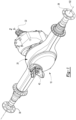
Figure 1 is a perspective view of an example of an axle assembly. -
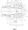
Figure 2 is a section view of a portion of the axle assembly along section line 2-2 showing an example of an interaxle differential unit. -
Figure 3 is an exploded view that includes the interaxle differential unit. -
Figure 4 is a section view of an annular case of the interaxle differential unit. -
Figure 5 is a magnified view of a portion ofFigure 4 . -
Figure 6 is a flowchart of a method of making the annular case and the interaxle differential unit. -
Figures 7-11 are images associated with some of the method steps. - As required, detailed embodiments of the present invention are disclosed herein; however, it is to be understood that the disclosed embodiments are merely exemplary of the invention that may be embodied in various and alternative forms. The figures are not necessarily to scale; some features may be exaggerated or minimized to show details of particular components. Therefore, specific structural and functional details disclosed herein are not to be interpreted as limiting, but merely as a representative basis for teaching one skilled in the art to variously employ the present invention.
- Referring to
Figure 1 , an example of anaxle assembly 10 is shown. Theaxle assembly 10 may be provided with a vehicle of any suitable type, such as a truck, bus, farm equipment, military transport or weaponry vehicle, or cargo loading equipment for land, air, or marine vessels. - The
axle assembly 10 may be part of a vehicle drivetrain that may include multiple axle assemblies that may be connected in series. For instance, theaxle assembly 10 may be part of a tandem axle configuration that may include two axle assemblies connected in series. Theaxle assembly 10 that is operatively connected to at least one torque source, such as an electric motor or an internal combustion engine, may be referred to as a first axle assembly. The axle assembly that receives propulsion torque from the torque source by way of the first axle assembly may be referred to as a second axle assembly. InFigure 1 , theaxle assembly 10 is depicted as being a first axle assembly. - The
axle assembly 10 may provide torque to its associated wheel assemblies and may provide torque to the second axle assembly. As best shown with reference toFigures 1 and2 , theaxle assembly 10 may include ahousing 20, aninput yoke 22, aninput shaft 24, afirst gear 26, aclutch collar 28, a drivengear 30, adrive pinion 32, adifferential assembly 34, at least oneaxle shaft 36, an interaxledifferential unit 38, anoutput shaft 40, anoutput yoke 42, or combinations thereof. These components are shown to facilitate an abbreviated discussion of the operation of theaxle assembly 10. - Referring to
Figure 1 , thehousing 20 may receive various components of theaxle assembly 10. In addition, thehousing 20 may facilitate mounting of theaxle assembly 10 to the vehicle. - The
input yoke 22 may facilitate coupling of theaxle assembly 10 to a torque source. Theinput yoke 22 may be operatively connected to theinput shaft 24. It is contemplated that theinput yoke 22 may be omitted, such as when a torque source like an electric motor is integrated with theaxle assembly 10. - Referring to
Figures 2 and3 , an example of aninput shaft 24 is shown. Theinput shaft 24 may extend along and may be configured to rotate about anaxis 50. For example, theinput shaft 24 may be rotatably supported by one or more bearings that may be disposed on thehousing 20. Theinput shaft 24 may be operatively connected to the interaxledifferential unit 38. In at least one configuration, theinput shaft 24 may include afirst spline 60 that may engage theclutch collar 28. - Referring to
Figures 2 and3 , thefirst gear 26, which may also be referred to as a drive gear, may be part of an interaxle differential unit gear nest of the interaxledifferential unit 38 as will be discussed in more detail below. Thefirst gear 26 may be rotatable about theaxis 50. In addition, thefirst gear 26 may be selectively coupled to theinput shaft 24 with theclutch collar 28. For instance, thefirst gear 26 may be rotatable about theaxis 50 with theinput shaft 24 when theclutch collar 28 couples thefirst gear 26 to theinput shaft 24 and thefirst gear 26 may be rotatable about theaxis 50 with respect to theinput shaft 24 when theclutch collar 28 does not couple thefirst gear 26 to theinput shaft 24. In at least one configuration, thefirst gear 26 may have a center bore that may receive theinput shaft 24 and optionally a bearing that may rotatably support thefirst gear 26 on theinput shaft 24. In at least one configuration, thefirst gear 26 may includeouter gear teeth 70,face gear teeth 72, andside gear teeth 74. - The
outer gear teeth 70 may engage and may mesh with teeth on the drivengear 30. Theouter gear teeth 70 may extend away from theaxis 50 and may be arranged around an outside diameter of thefirst gear 26. - The
face gear teeth 72 may include a set of teeth that may be arranged on a side or face of thefirst gear 26 that may face away from the interaxledifferential unit 38 and toward theclutch collar 28. Theface gear teeth 72 may selectively engage teeth on theclutch collar 28, such as when theclutch collar 28 couples thefirst gear 26 to theinput shaft 24. - Referring to
Figure 3 , theside gear teeth 74 may be disposed on an opposite side of thefirst gear 26 from theface gear teeth 72. Theside gear teeth 74 may be arranged around theaxis 50 and that may face toward gears that may be disposed inside the interaxledifferential unit 38. - Referring to
Figures 2 and3 , theclutch collar 28, if provided, may be moveable along theaxis 50 to engage or disengage thefirst gear 26. In at least one configuration, theclutch collar 28 may be generally ring-shaped and may define aclutch collar hole 80, aclutch collar spline 82, a clutchcollar face gear 84, and anannular groove 86. - Referring to
Figure 3 , theclutch collar hole 80 may extend around theaxis 50. Theclutch collar hole 80 may receive theinput shaft 24. - Referring to
Figures 2 and3 , theclutch collar spline 82 may be disposed in theclutch collar hole 80. Theclutch collar spline 82 may include a plurality of spline teeth that may extend toward theaxis 50 and that may mate or mesh with the teeth of thefirst spline 60 of theinput shaft 24. As such, theclutch collar 28 may be rotatable about theaxis 50 with theinput shaft 24 and may be moveable along theaxis 50 or moveable in an axial direction with respect to theinput shaft 24. - The clutch
collar face gear 84 may include a set of teeth that may be arranged around theaxis 50 and that may face toward and extend toward theface gear teeth 72 of thefirst gear 26. The teeth of the clutchcollar face gear 84 may selectively engage the teeth of theface gear teeth 72 of thefirst gear 26. - The
annular groove 86 may receive a linkage, such as a fork, that may operatively connect theclutch collar 28 to an actuator that may position theclutch collar 28 along theaxis 50. - Referring to
Figure 2 , the drivengear 30 may be rotatable about asecond axis 90. For example, thedrive pinion 32 may be received in a center bore of the drivengear 30 and the drivengear 30 may be fixedly disposed on thedrive pinion 32 or may be couplable to thedrive pinion 32 such that the drivengear 30 and thedrive pinion 32 may rotate together about thesecond axis 90. The drivengear 30 may include a plurality of teeth that may be generally arranged about an outside diameter of the drivengear 30 and that may mate or mesh with the teeth of theouter gear teeth 70 of thefirst gear 26. Only a portion of the drivengear 30 disposed above thesecond axis 90 is shown inFigure 2 . Thesecond axis 90 may be disposed substantially parallel to theaxis 50. The term "substantially parallel" as used herein means the same as or very close to parallel and includes features or axes that are within ±2° of being parallel each other. - The
drive pinion 32 may operatively connect the torque source to thedifferential assembly 34. Thedrive pinion 32 may be spaced apart from theinput shaft 24 and may be configured to rotate about an axis, such as asecond axis 90. Thedrive pinion 32 may rotate with the drivengear 30. It is also contemplated that thedrive pinion 32 may rotate about theaxis 50 in other configurations, such as when thefirst gear 26 and the drivengear 30 are omitted or when theoutput shaft 40 extends through thedrive pinion 32. A gear portion may be disposed at an end of thedrive pinion 32. - The
differential assembly 34 may be at least partially received in thehousing 20. Only a portion of thedifferential assembly 34 is shown. Thedifferential assembly 34 may be rotatable about an axis, such as a differential axis that may be disposed substantially perpendicular to thesecond axis 90. The term "substantially perpendicular" is used herein to designate features or axes that are the same as or very close to perpendicular and includes features that are within ±2° of being perpendicular each other. Thedifferential assembly 34 may transmit torque to theaxle shafts 36 and wheels. For example, thedifferential assembly 34 may be operatively connected to theaxle shafts 36 and may permit theaxle shafts 36 to rotate at different rotational speeds in a manner known by those skilled in the art. Thedifferential assembly 34 may have aring gear 100 that may have teeth that may mate or mesh with the teeth of the gear portion of thedrive pinion 32. Accordingly, thedifferential assembly 34 may receive torque from thedrive pinion 32 via thering gear 100 and transmit torque to theaxle shafts 36. - Referring to
Figure 1 , theaxle shafts 36 may transmit torque from thedifferential assembly 34 to corresponding wheel hubs and wheels. Theaxle shafts 36 may extend along and may be rotatable about athird axis 102, which may be the differential axis. Eachaxle shaft 36 may have a first end and a second end. The first end may be operatively connected to thedifferential assembly 34. The second end may be disposed opposite the first end and may be operatively connected to a wheel. - Referring to
Figures 2 and3 , an example of an interaxledifferential unit 38 is shown. The interaxledifferential unit 38 may accommodate or compensate for rotational speed differences between different drive axle assemblies, such as speed differences between theaxle assembly 10 and a second axle assembly that is connected in series with theaxle assembly 10. The interaxledifferential unit 38 may be provided in various locations. InFigure 3 , the interaxledifferential unit 38 is disposed inside thehousing 20 on theinput shaft 24; however, it is contemplated that the interaxledifferential unit 38 may be provided in other locations, such as closer to theoutput yoke 42 or with the second axle assembly. It is also contemplated that interaxledifferential unit 38 may be disposed on a shaft other than theinput shaft 24. In at least one configuration, the interaxledifferential unit 38 may include an interaxle differentialunit gear nest 110 and anannular case 112. - The interaxle differential
unit gear nest 110 may include a plurality of gears that may operatively connect theinput shaft 24 to theoutput shaft 40. In at least one configuration, the interaxle differentialunit gear nest 110 may include asecond gear 120, aspider 122, and a plurality of pinion gears 124. The interaxle differentialunit gear nest 110 may also include thefirst gear 26. - The
second gear 120 may be disposed proximate theinput shaft 24. For example, thesecond gear 120 may extend along theaxis 50 and may have a center bore that may receive and/or support an end of theinput shaft 24. A bearing may be provided in the center bore between theinput shaft 24 andsecond gear 120 to facilitate alignment and relative rotation. The center bore may also include a spline or splined portion that may be spaced apart from theinput shaft 24 and that may receive and engage a corresponding spline on another shaft, such as theoutput shaft 40. As such, thesecond gear 120 may not rotate about theaxis 50 with respect to theoutput shaft 40. - Referring to
Figures 2 and3 , thespider 122 may be fixedly disposed on theinput shaft 24. For instance, thespider 122 may include a center bore that may include splines that may mate with corresponding splines on theinput shaft 24 to help align and secure thespider 122 to theinput shaft 24. As such, thespider 122 may rotate about theaxis 50 with theinput shaft 24. Thespider 122 may also include one ormore pins 130 that may extend away from the center bore of thespider 122. - One or more pinion gears 124 may be rotatable with respect to the
spider 122. Apinion gear 124 may be rotatably disposed on apin 130. Thepinion gear 124 may include teeth that may mesh or mate with theside gear teeth 74 of thefirst gear 26 and may mesh or mate with teeth of thesecond gear 120. - The
annular case 112 may receive the interaxle differentialunit gear nest 110. Theannular case 112 may be a continuous seamless ring that may be made from a single piece of material and may not be an assembly of multiple parts. As such, theannular case 112 may not have free ends that meet each other and may be free of welds or joining seams. In addition, the cross-sectional profile of theannular case 112 around theaxis 50 may be constant or symmetrical as is best shown inFigure 4 . In at least one configuration and as is best shown with reference toFigures 3 and4 , theannular case 112 may have afirst end surface 140, asecond end surface 142, afirst opening 144, asecond opening 146, and may define anannular case cavity 148. Theannular case 112 may also include a firstenlarged lip 150, a secondenlarged lip 152, acenter portion 154, anannular groove 156, or combinations thereof. - The
first end surface 140 may be disposed at a first end of theannular case 112. For instance, thefirst end surface 140 may face toward thefirst gear 26. Thefirst end surface 140 may extend around theaxis 50 and may encircle thefirst opening 144. In addition, thefirst end surface 140 may be disposed substantially perpendicular to theaxis 50. - The
second end surface 142 may be disposed at an opposite end of theannular case 112 from thefirst end surface 140. As such, thesecond end surface 142 may face away from thefirst gear 26. Thesecond end surface 142 may extend around theaxis 50 and may encircle thesecond opening 146. In addition, thesecond end surface 142 may be disposed substantially perpendicular to theaxis 50. - Referring to
Figure 4 , thefirst opening 144 may extend around theaxis 50. Thefirst opening 144 may be encircled by thefirst end surface 140. In at least one configuration, thefirst opening 144 may have a larger diameter than thesecond opening 146. - The
second opening 146 may be disposed at an opposite end of theannular case 112 from thefirst opening 144. Thesecond opening 146 may extend around theaxis 50. Thesecond opening 146 may be encircled by thesecond end surface 142. In at least one configuration, thefirst opening 144 and thesecond opening 146 may be the only holes or openings in theannular case 112. As such, no other through holes or blind holes may be provided in or defined by theannular case 112. - The first
enlarged lip 150 may extend from thefirst end surface 140. The firstenlarged lip 150 may have a greater wall thickness than thecenter portion 154. In at least one configuration, the firstenlarged lip 150 may extend in an axial direction between thefirst end surface 140 and thecenter portion 154 and may extend radially from a curved interior surface that may face toward theaxis 50 to an exterior surface that may extend substantially parallel to theaxis 50. - The second
enlarged lip 152 may extend from thesecond end surface 142. The secondenlarged lip 152 may have a greater axial length than the firstenlarged lip 150. In at least one configuration and as is best shown inFigure 5 , the secondenlarged lip 152 may have aninner lip surface 160 and anouter lip surface 162. Theinner lip surface 160 may encircle theaxis 50 and may extend substantially parallel to theaxis 50. Theouter lip surface 162 may be disposed in a nonparallel relationship with theinner lip surface 160. For example, theouter lip surface 162 may extend at an angle with respect to theaxis 50 such that theouter lip surface 162 extends further from theaxis 50 as the distance from thesecond end surface 142 increases. - The
center portion 154 may be axially positioned between the firstenlarged lip 150 and the secondenlarged lip 152. Thecenter portion 154 may have a part-spherical surface 170 that may face toward theaxis 50. The part-spherical surface 170 may extend continuously around theaxis 50 and may be disposed at a substantially constant radial distance from acenter point 250 that may be positioned along theaxis 50. For instance, the part-spherical surface 170 may resemble a portion of a sphere and may extend around a spherical segment, which may be a portion of a sphere that may be disposed between two substantially parallel planes that may be disposed substantially perpendicular to theaxis 50. - Referring primarily to
Figure 5 , theannular groove 156 may be axially positioned between the firstenlarged lip 150 and the part-spherical surface 170 of thecenter portion 154. Theannular groove 156 may face toward theaxis 50 and may extend outward or away from theaxis 50 with respect to the part-spherical surface 170 and may extend from an end of the part-spherical surface 170. Theannular groove 156 may also be disposed further from theaxis 50 than theinner lip surface 160. - Referring to
Figure 2 , theoutput shaft 40 may extend along and may be configured to rotate about theaxis 50. For instance, theoutput shaft 40 may be supported by one or more bearings that may be disposed on thehousing 20. Theoutput shaft 40 may be coupled to the interaxledifferential unit 38. For example, theoutput shaft 40 may be fixedly coupled to thesecond gear 120. - Referring to
Figure 1 , theoutput yoke 42 may facilitate coupling of theaxle assembly 10 to another axle assembly. For instance, theoutput yoke 42 may be fixedly coupled to theoutput shaft 40 and may be operatively connected to a second axle assembly in any suitable manner, such as via a prop shaft. - Referring to
Figure 6 , a flowchart of a method of making an interaxle differential unit is shown. Many steps of the method are associated with making theannular case 112. Pictorial representations of some of these steps are shown inFigures 7-11 . - At
block 200, a workpiece may be provided. An example of aworkpiece 220 is shown inFigure 7 . Theworkpiece 220 is single piece of material that may be made of ASTM 52100 bearing steel. Theworkpiece 220 may be a piece of bar stock that may be cut to a predetermined length. Theworkpiece 220 may have any suitable cross-sectional shape. For instance, theworkpiece 220 may have a cylindrical cross section. - At
block 202, theworkpiece 220 may be heated to soften the material and facilitate forming. For example, theworkpiece 220 may be heated in a furnace in a manner known by those skilled in the art. - At
block 204, theworkpiece 220 may be flattened. An example of a flattenedworkpiece 220 is shown inFigure 8 . Theworkpiece 220 may be flattened after theworkpiece 220 is heated. Theworkpiece 220 may be flattened to form a generally cylindrical solid disc that may have an increased diameter and a reduced height as compared toFigure 7 . Theworkpiece 220 may be flattened in any suitable manner, such as with rollers, a forging press, or the like. - At block 206, the
workpiece 220 is pierced. An example of apierced workpiece 220 is shown inFigure 9 . Piercing theworkpiece 220 creates a throughhole 222 at or near the center of theworkpiece 220. The throughhole 222 may be disposed along acenter axis 230. Theworkpiece 220 may be pierced after theworkpiece 220 has been heated and flattened. Theworkpiece 220 may be pierced in any suitable manner, such as with a tool like a piercing die that may be inserted from thetop side 224 to thebottom side 226 of theworkpiece 220. Theworkpiece 220 may be a seamless ring that may have a generally rectilinear cross-section after piercing and may include aninner side 240 that may face toward thecenter axis 230 and anouter side 242 that may be disposed opposite theinner side 240 and that may face away from thecenter axis 230. - At
block 208, theworkpiece 220 is ring roll forged to form the annular case. Ring roll forging may occur after theworkpiece 220 has been heated and pierced and may include a sequence of ring roll forging steps. - For instance, a first ring roll forging step may reduce the wall thickness W of the
workpiece 220, may increase the inside diameter of theworkpiece 220 or diameter of the throughhole 222, and may increase the outside diameter of theworkpiece 220 as shown inFigure 10 . Theworkpiece 220 may have a different rectilinear cross-section after the first ring roll forging step as compared to the cross-section of theworkpiece 220 after piercing. The ring roll forging steps may be accomplished using a plurality of rollers in a manner known by those skilled in the art. For example, an axial roller may roll along thetop side 224, thebottom side 226, or both. An idler roller and a drive roller may roll along theinner side 240 and theouter side 242, respectively, and may move away from thecenter axis 230 of the throughhole 222 during ring roll forging to increase the inside diameter and the outside diameter of theworkpiece 220 and to help reduce the wall thickness W of theworkpiece 220. Theinner side 240 may be disposed substantially parallel to theouter side 242 during the first ring roll forging step. Theworkpiece 220 may be rotated about thecenter axis 230 during ring roll forging. - The
workpiece 220 may undergo one or more additional ring roll forging steps to change the rectilinear cross-section to a non-rectilinear cross-section. For instance, one or more additional ring roll forging steps may contour theinner side 240 and theouter side 242 and alter the wall thickness W therebetween to provide a desired cross-sectional shape, such as that shown inFigure 4 . Such steps may also be accomplished using a plurality of rollers in a manner known by those skilled in the art. For instance, a sequence of rollers may roll along theinner side 240 and theouter side 242 to progressively form theinner side 240 and theouter side 242 to a desired cross sectional profile such as is shown inFigure 4 . Theworkpiece 220 may be referred to as an annular case after ring roll forging is complete. An example of theworkpiece 220 after ring roll forging is shown inFigure 11 . Thetop side 224 or a portion thereof may become or may be referred to as afirst end surface 140 of the annular case that is shown inFigure 4 after ring roll forging is complete. Similarly, thebottom side 226 or a portion thereof may become or may be referred to as asecond end surface 142 of the annular case after ring roll forging is complete. - In the cross sectional profile shown in
Figure 4 , the majority of theinner side 240 may not be disposed parallel to theouter side 242 in contrast to the generally parallel positioning that may be associated with the first ring roll forging step as shown inFigure 10 . For instance forming the cross sectional profile may include increasing the inside diameter of theinner side 240 between thefirst end surface 140 and thesecond end surface 142, such as at the part-spherical surface 170 such that at least a portion of theinner side 240 may have a larger diameter than thefirst end surface 140 and thesecond end surface 142. As such, thefirst opening 144 and thesecond opening 146 may have smaller diameters than a portion of theinner side 240 that is axially positioned between them. - The
workpiece 220 may be annealed after ring roll forging is complete to strengthen theworkpiece 220 and to facilitate material handling. - At
block 210, theworkpiece 220 may be machined. Machining may remove material from predetermined locations of theworkpiece 220. For instance, material may be removed from thefirst end surface 140, thesecond end surface 142, or both, after ring roll forging and before heat treating. Any suitable material removal process may be used. For example, material may be removed with a cutting tool in a manner but known by those skilled in the art. - At
block 212, theworkpiece 220 is heat treated to harden theworkpiece 220. Heat treating may include martempering theentire workpiece 220 and thus the entire annular case. For example, theworkpiece 220 may be heated above the upper critical point of the material from which it is made. For instance, theworkpiece 220 may be heated to a temperature of 830°C to 845°C to austenitize the workpiece in a neutral atmosphere to prevent decarbonization of the workpiece. The workpiece may be held at this temperature until the temperature becomes uniform throughout the cross section of theworkpiece 220. Then, theworkpiece 220 may then be quenched in a salt, oil, or lead bath having a temperature of 5°C to 15°C below the martensite start temperature of the material from which theworkpiece 220 is made. Theworkpiece 220 may be quenched for a predetermined period of time, such as approximately 4-5 minutes. Then, theworkpiece 220 may be allowed to air cool to room temperature or ambient temperature. Theworkpiece 220 may have a surface hardness and an internal hardness or core through hardness of at leastHRC 60 after heat treating. Theworkpiece 220 may then be tempered after quenching. For instance, theworkpiece 220 may be tempered at a temperature of 175°C to 185°C for approximately 250 to 260 minutes within one hour of quenching. - At
block 214, the grinding of theworkpiece 220 may occur. Grinding may remove material from predetermined locations of theworkpiece 220. For example, thefirst end surface 140, thesecond end surface 142, or both, may undergo grinding after heat treating to provide a desired surface finish that may facilitate operation of the interaxle differential unit when in use. - At
block 216, the interaxle differential unit is assembled. The interaxle differential unit is assembled by installing the interaxle unitdifferential gear nest 110 inside theannular case 112. For instance, one or more pinion gears 124 may be mounted on thespider 122, thespider 122 and pinion gears 124 may be inserted through an opening of theannular case 112, such as thefirst opening 144, and into theannular case 112, and gears such as thefirst gear 26 and thesecond gear 120 may be brought into engagement with the pinion gears 124 by inserting them into thefirst opening 144 and thesecond opening 146, respectively. - The present invention may allow an interaxle differential unit to be provided with a one-piece annular case that may be manufactured more efficiently and may require fewer assembly steps than multi piece case designs. In addition, an annular case and an interaxle differential unit may be provided with less weight, which may help reduce material usage and vehicle energy consumption. The annular case may have improved durability as compared to multi case designs or interaxle differential unit cases that may be made of heat treat cast iron. For instance, the inner side of the annular case may better withstand friction associated with rotating pinion gears, which may rotate at high speeds during spinout conditions in which the rotational speed of one axle assembly greatly differs from another that is connected in series. As a result, wear or damage to the annular case caused by spinning pinion gears may be reduced or avoided, thereby increasing the durability and potential life of the interaxle differential unit.
- While exemplary embodiments are described above, it is not intended that these embodiments describe all possible forms of the invention. Rather, the words used in the specification are words of description rather than limitation, and it is understood that various changes may be made without departing from the scope of the invention as defined by the appended claims. Additionally, the features of various implementing embodiments may be combined to form further embodiments of the invention.
Claims (15)
- A method of making an interaxle differential unit (38), the method comprising:piercing a workpiece (220) to form a through hole (222);ring roll forging the workpiece (220) to form an annular case (112) that is a seamless ring;heat treating the annular case (112); andinstalling an interaxle differential unit gear nest (110) inside the annular case (112).
- The method of claim 1 wherein the annular case (112) defines a first opening (144) and a second opening (146) that are disposed along an axis (50) about which the interaxle differential unit (38) is rotatable, wherein the first opening (144) has a larger diameter than the second opening (146).
- The method of claim 2 wherein the first opening (144) and the second opening (146) are the only holes in the annular case (112).
- The method of claim 1 wherein the annular case (112) defines a first opening (144) and a second opening (146) that are disposed along an axis (50) about which the interaxle differential unit (38) is rotatable, and the interaxle differential unit gear nest (110) includes a first gear (26) and a second gear (120), wherein the first gear (26) is received in the first opening (144) and the second gear (120) is received in the second opening (146), preferably the interaxle differential unit gear nest (110) includes a spider (122) and a pinion gear (124), wherein the pinion gear (124) is engageable with the first gear (26) and the second gear (120) and is mounted on the spider (122) such that the pinion gear (124) is rotatable with respect to the spider (122) and the spider (122) and the pinion gear (124) are installed inside the annular case (112) before the first gear (26) is received in the first opening (144).
- The method of claim 1 further comprising heating and flattening the workpiece (220) before piercing the workpiece (220), preferably flattening the workpiece (220) forms a solid disc.
- The method of claim 1 wherein ring roll forging the workpiece (220) includes rotating the workpiece (220) about a center axis (230), increasing a diameter of the through hole (222), and increasing an outside diameter of the workpiece (220) to reduce a wall thickness of the workpiece (220) between the diameter of the through hole (222) and the outside diameter of the workpiece (220), preferably the outside diameter is defined by an outer side (242) and the diameter of the through hole (222) is defined by an inner side (240) that is disposed substantially parallel to the outer side (242).
- The method of claim 6 wherein ring roll forging the workpiece (220) further comprises forming the outer side (242) and the inner side (240) to form a cross sectional profile in which a majority of the inner side (240) is not disposed parallel to the outer side (242) after increasing the diameter and the outside diameter and reducing the wall thickness of the workpiece (220).
- The method of claim 7 wherein forming the cross sectional profile includes increasing the inside diameter of the inner side (240) between a first end surface (140) and a second end surface (142) of the annular case (112) such that at least a portion of the inner side (240) has a larger diameter than a first opening (144) that is encircled by the first end surface (140) and a second opening (146) that is encircled by the second end surface (142).
- The method of claim 1 further comprising removing material from a first end surface (140) and a second end surface (142) of the annular case (112) after ring roll forging and before heat treating the annular case (112), preferably removing material includes grinding the first end surface (140) of the annular case (112) after heat treating and before installing an interaxle differential unit gear nest (110).
- The method of claim 1 wherein heat treating the annular case (112) includes martempering the entire annular case (112) and/or the annular case (112) has a surface and core through hardness of at least HRC 60 after heat treating.
- The method of claim 1 wherein the annular case (112) has a surface and core through hardness of at least HRC 60 after heat treating.
- The method of claim 1 wherein the annular case (112) is made of ASTM 52100 bearing steel and heat treating the annular case (112) includes heating the annular case (112) to 830°C to 845°C in a neutral atmosphere to prevent decarburization and quenching the annular case (112) in a bath having a temperature of 5°C to 15°C below a martensite start temperature of the ASTM 52100 bearing steel.
- The method of claim 1 wherein the annular case (112) includes a first end surface (140) that encircles a first opening (144), a second end surface (142) that encircles a second opening (146), a first enlarged lip (150) that extends from the first end surface (140), and a second enlarged lip (152) that extends from the second end surface (142), wherein the first enlarged lip (150) and the second enlarged lip (152) have a greater wall thickness than a center portion (154) of the annular case (112) that is axially positioned between the first enlarged lip (150) and the second enlarged lip (152).
- The method of claim 13 wherein ring roll forging the annular case (112) forms an annular groove (156) that is axially positioned between the first enlarged lip (150) and a part-spherical surface (170) of the center portion (154).
- The method of claim 13 wherein the second enlarged lip (152) has a greater axial length than the first enlarged lip (150), and the second enlarged lip (152) includes an inner lip surface (160) that encircles an axis (50) and that extends substantially parallel to the axis (50) and an outer lip surface (162) that is disposed in a nonparallel relationship with the inner lip surface (160) and that extends further from the axis (50) as a distance from the second end surface (142) increases.
Priority Applications (1)
| Application Number | Priority Date | Filing Date | Title |
|---|---|---|---|
| EP24201218.5A EP4459155A3 (en) | 2021-03-09 | 2022-03-03 | Method of making an interaxle differential unit |
Applications Claiming Priority (1)
| Application Number | Priority Date | Filing Date | Title |
|---|---|---|---|
| US17/196,178 US12331820B2 (en) | 2021-03-09 | 2021-03-09 | Method of making an interaxle differential unit and an annular case |
Related Child Applications (1)
| Application Number | Title | Priority Date | Filing Date |
|---|---|---|---|
| EP24201218.5A Division EP4459155A3 (en) | 2021-03-09 | 2022-03-03 | Method of making an interaxle differential unit |
Publications (2)
| Publication Number | Publication Date |
|---|---|
| EP4056295A1 EP4056295A1 (en) | 2022-09-14 |
| EP4056295B1 true EP4056295B1 (en) | 2024-10-16 |
Family
ID=80787135
Family Applications (2)
| Application Number | Title | Priority Date | Filing Date |
|---|---|---|---|
| EP22159901.2A Active EP4056295B1 (en) | 2021-03-09 | 2022-03-03 | Method of making an interaxle differential unit |
| EP24201218.5A Pending EP4459155A3 (en) | 2021-03-09 | 2022-03-03 | Method of making an interaxle differential unit |
Family Applications After (1)
| Application Number | Title | Priority Date | Filing Date |
|---|---|---|---|
| EP24201218.5A Pending EP4459155A3 (en) | 2021-03-09 | 2022-03-03 | Method of making an interaxle differential unit |
Country Status (3)
| Country | Link |
|---|---|
| US (2) | US12331820B2 (en) |
| EP (2) | EP4056295B1 (en) |
| CN (1) | CN115041623A (en) |
Families Citing this family (5)
| Publication number | Priority date | Publication date | Assignee | Title |
|---|---|---|---|---|
| US20240262191A1 (en) * | 2023-02-08 | 2024-08-08 | The Hilliard Corporation | Positive Drive Differential |
| US12496902B2 (en) | 2023-02-08 | 2025-12-16 | The Hilliard Corporation | Positive drive differential with pinion disconnect |
| CZ2023443A3 (en) | 2023-11-15 | 2024-12-18 | Tatra Trucks A.S. | Center differential and chassis for mounting special bodywork with backbone chassis with independent wheel bearings, containing center differential |
| CZ310237B6 (en) | 2023-11-15 | 2024-12-18 | TATRA TRUCKS a.s | A carrier and a casing of inter-axle differential and the inter-axle differential |
| CZ310236B6 (en) | 2023-11-15 | 2024-12-18 | TATRA TRUCKS a.s | Interaxle coupling with integrated differentials |
Family Cites Families (31)
| Publication number | Priority date | Publication date | Assignee | Title |
|---|---|---|---|---|
| US3700082A (en) * | 1970-07-09 | 1972-10-24 | Hy Torq Corp | Differential drive mechanism |
| SE440134B (en) * | 1983-01-11 | 1985-07-15 | Volvo Ab | DIFFERENTIALVEXEL |
| GB2155867B (en) | 1984-01-28 | 1987-06-03 | Leyland Vehicles | Axle casing |
| JP2689819B2 (en) | 1992-06-01 | 1997-12-10 | 株式会社豊田自動織機製作所 | Differential housing in axle housing |
| EP0683333B1 (en) * | 1994-05-18 | 1997-10-01 | Dr.Ing.h.c. F. Porsche Aktiengesellschaft | Axle drive differential for motor vehicles |
| JPH08312753A (en) | 1995-05-17 | 1996-11-26 | Dr Ing H C F Porsche Ag | Differential device for automobile axle drive |
| JP2001087836A (en) | 1999-09-17 | 2001-04-03 | Kobe Steel Ltd | Special shaped ring |
| US20070191171A1 (en) * | 2003-09-15 | 2007-08-16 | Pascoe David M | Differential with die formed housing |
| US6940056B2 (en) * | 2003-10-09 | 2005-09-06 | Visteon Global Technologies, Inc. | Induction heat treatment method and coil and article treated thereby |
| US7367914B2 (en) * | 2005-02-25 | 2008-05-06 | Ronjo Company | Differential housing support member |
| US8230597B2 (en) * | 2008-10-03 | 2012-07-31 | Ford Global Technologies, Llc | Forming preforms and parts therefrom |
| US8628444B2 (en) * | 2010-07-01 | 2014-01-14 | Metal Forming & Coining Corporation | Flow-formed differential case assembly |
| WO2012151385A2 (en) * | 2011-05-03 | 2012-11-08 | Inductoheat, Inc. | Forging of an annular article with electric induction heating |
| US8398520B1 (en) | 2011-09-30 | 2013-03-19 | Arvinmeritor Technology, Llc | Drive axle assembly and disengagement system |
| US9702448B2 (en) * | 2012-05-22 | 2017-07-11 | Eaton Corporation | Differential having light weight bevel gearing |
| DE102012106405B4 (en) * | 2012-07-17 | 2016-06-16 | Kirchhoff Automotive Deutschland Gmbh | Method for producing a deformed and at least partially hardened sheet metal component and use of a press-hardening tool for producing such a component |
| US9566671B2 (en) * | 2013-05-22 | 2017-02-14 | Eaton Capital | Method for manufacturing a forging |
| US9719563B2 (en) | 2015-05-22 | 2017-08-01 | Arvinmeritor Technology, Llc | Axle assembly having a tapered spline arrangement |
| DE102015111137B4 (en) | 2015-07-09 | 2022-05-12 | Thyssenkrupp Ag | Process for manufacturing a ring with a toothing |
| US10113628B2 (en) | 2015-08-11 | 2018-10-30 | Arvinmeritor Technology, Llc | Axle assembly having a clutch collar actuator mechanism |
| US9816603B2 (en) | 2015-09-11 | 2017-11-14 | Arvinmeritor Technology, Llc | Axle assembly with interaxle differential lubrication |
| US10156289B2 (en) * | 2017-03-07 | 2018-12-18 | Meritor do Brasil Sistemas Automotivos Ltda. | Axle assembly having multiple clutch collars |
| US10208846B2 (en) | 2017-03-10 | 2019-02-19 | Arvinmeritor Technology, Llc | Axle assembly having a drive pinion support bearing and a method of assembly |
| US10539218B2 (en) | 2017-08-23 | 2020-01-21 | Arvinmeritor Technology, Llc | Axle assembly having a drive pinion assembly |
| US10364872B2 (en) | 2017-10-17 | 2019-07-30 | Arvinmeritor Technology, Llc | Axle assembly having a gear reduction unit and an interaxle differential unit |
| US10369885B2 (en) | 2017-10-17 | 2019-08-06 | Arvinmeritor Technology, Llc | Axle assembly having a gear reduction unit and an interaxle differential unit |
| US10703202B2 (en) * | 2018-02-12 | 2020-07-07 | Arvinmeritor Technology, Llc | Drive axle assembly with clutch collar |
| CN109351896B (en) | 2018-11-14 | 2020-12-04 | 湖北汽车工业学院 | A kind of rolling method of super-large diameter 6061 aluminum alloy special-shaped section ring |
| US11209077B2 (en) | 2019-08-12 | 2021-12-28 | Dana Heavy Vehicle Systems Group, Llc | Inter-axle differential assembly |
| CN210799941U (en) | 2019-08-15 | 2020-06-19 | 一汽解放汽车有限公司 | A axle reducer assembly |
| CN112122543B (en) | 2020-09-03 | 2022-07-22 | 豪梅特航空机件(苏州)有限公司 | Forging method for refining crystal grains of In783 alloy thick-wall ring forging |
-
2021
- 2021-03-09 US US17/196,178 patent/US12331820B2/en active Active
-
2022
- 2022-03-03 EP EP22159901.2A patent/EP4056295B1/en active Active
- 2022-03-03 EP EP24201218.5A patent/EP4459155A3/en active Pending
- 2022-03-04 CN CN202210210619.XA patent/CN115041623A/en active Pending
-
2025
- 2025-05-09 US US19/203,899 patent/US20250271053A1/en active Pending
Also Published As
| Publication number | Publication date |
|---|---|
| US20250271053A1 (en) | 2025-08-28 |
| EP4459155A3 (en) | 2025-01-29 |
| CN115041623A (en) | 2022-09-13 |
| BR102022004215A2 (en) | 2022-09-20 |
| US12331820B2 (en) | 2025-06-17 |
| EP4459155A2 (en) | 2024-11-06 |
| EP4056295A1 (en) | 2022-09-14 |
| US20220290750A1 (en) | 2022-09-15 |
Similar Documents
| Publication | Publication Date | Title |
|---|---|---|
| EP4056295B1 (en) | Method of making an interaxle differential unit | |
| US6176152B1 (en) | Housing for a differential mechanism of an automotive vehicle | |
| US7695392B2 (en) | Differential mechanism assembly | |
| US8544174B2 (en) | Differential mechanism having multiple case portions | |
| US6045479A (en) | Differential mechanism for an automotive vehicle having a cold formed housing assembly | |
| US7819040B2 (en) | Method for making vehicle axle differential casing and resultant product | |
| US10207536B2 (en) | Drive wheel bearing and method of manufacturing the same | |
| US20160075179A1 (en) | Axle Assembly With Inboard Axle Shaft Bearings That Support A Differential Mechanism | |
| KR20020096879A (en) | Two piece axle shaft | |
| EP2937587B1 (en) | Manufacturing method for outer joint member of constant velocity universal joint and outer joint member | |
| JP2010048348A (en) | Bearing apparatus for wheel | |
| EP1905849A1 (en) | Process for producing bearing device for wheel | |
| US20190056019A1 (en) | Differential assembly with two-piece carrier and welded ring gear | |
| EP2202421A1 (en) | Constant speed universal joint | |
| EP1284377A2 (en) | Input pinion shaft and method of manufacturing an input pinion shaft | |
| WO2013154015A1 (en) | Inner member of constant velocity universal joint and method for producing same | |
| CN107614910A (en) | The outside joint member of constant-speed universal coupling | |
| EP2113394B1 (en) | Bearing for wheel and method for manufacturing the same | |
| JP6385730B2 (en) | Method for manufacturing outer joint member of constant velocity universal joint and outer joint member | |
| BR102022004215B1 (en) | METHOD OF MANUFACTURING AN INTER-AXLE DIFFERENTIAL UNIT AND AN ANNULAR HOUSING | |
| JP2006026697A (en) | Hollow-shaped power transmission shaft | |
| US8661679B2 (en) | Bearing device for vehicle and method of manufacturing the same | |
| WO2025205018A1 (en) | Outer joint member for constant velocity universal joint |
Legal Events
| Date | Code | Title | Description |
|---|---|---|---|
| PUAI | Public reference made under article 153(3) epc to a published international application that has entered the european phase |
Free format text: ORIGINAL CODE: 0009012 |
|
| STAA | Information on the status of an ep patent application or granted ep patent |
Free format text: STATUS: THE APPLICATION HAS BEEN PUBLISHED |
|
| AK | Designated contracting states |
Kind code of ref document: A1 Designated state(s): AL AT BE BG CH CY CZ DE DK EE ES FI FR GB GR HR HU IE IS IT LI LT LU LV MC MK MT NL NO PL PT RO RS SE SI SK SM TR |
|
| STAA | Information on the status of an ep patent application or granted ep patent |
Free format text: STATUS: REQUEST FOR EXAMINATION WAS MADE |
|
| 17P | Request for examination filed |
Effective date: 20230228 |
|
| RBV | Designated contracting states (corrected) |
Designated state(s): AL AT BE BG CH CY CZ DE DK EE ES FI FR GB GR HR HU IE IS IT LI LT LU LV MC MK MT NL NO PL PT RO RS SE SI SK SM TR |
|
| P01 | Opt-out of the competence of the unified patent court (upc) registered |
Effective date: 20230531 |
|
| GRAP | Despatch of communication of intention to grant a patent |
Free format text: ORIGINAL CODE: EPIDOSNIGR1 |
|
| STAA | Information on the status of an ep patent application or granted ep patent |
Free format text: STATUS: GRANT OF PATENT IS INTENDED |
|
| RIC1 | Information provided on ipc code assigned before grant |
Ipc: F16H 57/037 20120101ALI20240429BHEP Ipc: B60K 17/16 20060101ALI20240429BHEP Ipc: B21K 1/26 20060101ALI20240429BHEP Ipc: B21J 1/04 20060101ALI20240429BHEP Ipc: B21J 5/10 20060101ALI20240429BHEP Ipc: B21H 1/06 20060101AFI20240429BHEP |
|
| INTG | Intention to grant announced |
Effective date: 20240517 |
|
| GRAS | Grant fee paid |
Free format text: ORIGINAL CODE: EPIDOSNIGR3 |
|
| GRAA | (expected) grant |
Free format text: ORIGINAL CODE: 0009210 |
|
| STAA | Information on the status of an ep patent application or granted ep patent |
Free format text: STATUS: THE PATENT HAS BEEN GRANTED |
|
| AK | Designated contracting states |
Kind code of ref document: B1 Designated state(s): AL AT BE BG CH CY CZ DE DK EE ES FI FR GB GR HR HU IE IS IT LI LT LU LV MC MK MT NL NO PL PT RO RS SE SI SK SM TR |
|
| REG | Reference to a national code |
Ref country code: GB Ref legal event code: FG4D |
|
| REG | Reference to a national code |
Ref country code: CH Ref legal event code: EP |
|
| REG | Reference to a national code |
Ref country code: IE Ref legal event code: FG4D |
|
| REG | Reference to a national code |
Ref country code: DE Ref legal event code: R096 Ref document number: 602022006763 Country of ref document: DE |
|
| REG | Reference to a national code |
Ref country code: LT Ref legal event code: MG9D |
|
| REG | Reference to a national code |
Ref country code: NL Ref legal event code: MP Effective date: 20241016 |
|
| REG | Reference to a national code |
Ref country code: AT Ref legal event code: MK05 Ref document number: 1732547 Country of ref document: AT Kind code of ref document: T Effective date: 20241016 |
|
| PG25 | Lapsed in a contracting state [announced via postgrant information from national office to epo] |
Ref country code: NL Free format text: LAPSE BECAUSE OF FAILURE TO SUBMIT A TRANSLATION OF THE DESCRIPTION OR TO PAY THE FEE WITHIN THE PRESCRIBED TIME-LIMIT Effective date: 20241016 |
|
| PG25 | Lapsed in a contracting state [announced via postgrant information from national office to epo] |
Ref country code: NL Free format text: LAPSE BECAUSE OF FAILURE TO SUBMIT A TRANSLATION OF THE DESCRIPTION OR TO PAY THE FEE WITHIN THE PRESCRIBED TIME-LIMIT Effective date: 20241016 |
|
| PG25 | Lapsed in a contracting state [announced via postgrant information from national office to epo] |
Ref country code: IS Free format text: LAPSE BECAUSE OF FAILURE TO SUBMIT A TRANSLATION OF THE DESCRIPTION OR TO PAY THE FEE WITHIN THE PRESCRIBED TIME-LIMIT Effective date: 20250216 Ref country code: HR Free format text: LAPSE BECAUSE OF FAILURE TO SUBMIT A TRANSLATION OF THE DESCRIPTION OR TO PAY THE FEE WITHIN THE PRESCRIBED TIME-LIMIT Effective date: 20241016 Ref country code: PT Free format text: LAPSE BECAUSE OF FAILURE TO SUBMIT A TRANSLATION OF THE DESCRIPTION OR TO PAY THE FEE WITHIN THE PRESCRIBED TIME-LIMIT Effective date: 20250217 |
|
| PG25 | Lapsed in a contracting state [announced via postgrant information from national office to epo] |
Ref country code: FI Free format text: LAPSE BECAUSE OF FAILURE TO SUBMIT A TRANSLATION OF THE DESCRIPTION OR TO PAY THE FEE WITHIN THE PRESCRIBED TIME-LIMIT Effective date: 20241016 |
|
| PG25 | Lapsed in a contracting state [announced via postgrant information from national office to epo] |
Ref country code: BG Free format text: LAPSE BECAUSE OF FAILURE TO SUBMIT A TRANSLATION OF THE DESCRIPTION OR TO PAY THE FEE WITHIN THE PRESCRIBED TIME-LIMIT Effective date: 20241016 |
|
| PG25 | Lapsed in a contracting state [announced via postgrant information from national office to epo] |
Ref country code: ES Free format text: LAPSE BECAUSE OF FAILURE TO SUBMIT A TRANSLATION OF THE DESCRIPTION OR TO PAY THE FEE WITHIN THE PRESCRIBED TIME-LIMIT Effective date: 20241016 |
|
| PG25 | Lapsed in a contracting state [announced via postgrant information from national office to epo] |
Ref country code: NO Free format text: LAPSE BECAUSE OF FAILURE TO SUBMIT A TRANSLATION OF THE DESCRIPTION OR TO PAY THE FEE WITHIN THE PRESCRIBED TIME-LIMIT Effective date: 20250116 |
|
| PG25 | Lapsed in a contracting state [announced via postgrant information from national office to epo] |
Ref country code: AT Free format text: LAPSE BECAUSE OF FAILURE TO SUBMIT A TRANSLATION OF THE DESCRIPTION OR TO PAY THE FEE WITHIN THE PRESCRIBED TIME-LIMIT Effective date: 20241016 Ref country code: LV Free format text: LAPSE BECAUSE OF FAILURE TO SUBMIT A TRANSLATION OF THE DESCRIPTION OR TO PAY THE FEE WITHIN THE PRESCRIBED TIME-LIMIT Effective date: 20241016 Ref country code: GR Free format text: LAPSE BECAUSE OF FAILURE TO SUBMIT A TRANSLATION OF THE DESCRIPTION OR TO PAY THE FEE WITHIN THE PRESCRIBED TIME-LIMIT Effective date: 20250117 |
|
| PG25 | Lapsed in a contracting state [announced via postgrant information from national office to epo] |
Ref country code: PL Free format text: LAPSE BECAUSE OF FAILURE TO SUBMIT A TRANSLATION OF THE DESCRIPTION OR TO PAY THE FEE WITHIN THE PRESCRIBED TIME-LIMIT Effective date: 20241016 |
|
| PG25 | Lapsed in a contracting state [announced via postgrant information from national office to epo] |
Ref country code: RS Free format text: LAPSE BECAUSE OF FAILURE TO SUBMIT A TRANSLATION OF THE DESCRIPTION OR TO PAY THE FEE WITHIN THE PRESCRIBED TIME-LIMIT Effective date: 20250116 |
|
| PG25 | Lapsed in a contracting state [announced via postgrant information from national office to epo] |
Ref country code: SM Free format text: LAPSE BECAUSE OF FAILURE TO SUBMIT A TRANSLATION OF THE DESCRIPTION OR TO PAY THE FEE WITHIN THE PRESCRIBED TIME-LIMIT Effective date: 20241016 |
|
| PG25 | Lapsed in a contracting state [announced via postgrant information from national office to epo] |
Ref country code: DK Free format text: LAPSE BECAUSE OF FAILURE TO SUBMIT A TRANSLATION OF THE DESCRIPTION OR TO PAY THE FEE WITHIN THE PRESCRIBED TIME-LIMIT Effective date: 20241016 |
|
| REG | Reference to a national code |
Ref country code: DE Ref legal event code: R097 Ref document number: 602022006763 Country of ref document: DE |
|
| PG25 | Lapsed in a contracting state [announced via postgrant information from national office to epo] |
Ref country code: EE Free format text: LAPSE BECAUSE OF FAILURE TO SUBMIT A TRANSLATION OF THE DESCRIPTION OR TO PAY THE FEE WITHIN THE PRESCRIBED TIME-LIMIT Effective date: 20241016 |
|
| PG25 | Lapsed in a contracting state [announced via postgrant information from national office to epo] |
Ref country code: RO Free format text: LAPSE BECAUSE OF FAILURE TO SUBMIT A TRANSLATION OF THE DESCRIPTION OR TO PAY THE FEE WITHIN THE PRESCRIBED TIME-LIMIT Effective date: 20241016 |
|
| PG25 | Lapsed in a contracting state [announced via postgrant information from national office to epo] |
Ref country code: SK Free format text: LAPSE BECAUSE OF FAILURE TO SUBMIT A TRANSLATION OF THE DESCRIPTION OR TO PAY THE FEE WITHIN THE PRESCRIBED TIME-LIMIT Effective date: 20241016 |
|
| PG25 | Lapsed in a contracting state [announced via postgrant information from national office to epo] |
Ref country code: CZ Free format text: LAPSE BECAUSE OF FAILURE TO SUBMIT A TRANSLATION OF THE DESCRIPTION OR TO PAY THE FEE WITHIN THE PRESCRIBED TIME-LIMIT Effective date: 20241016 |
|
| PG25 | Lapsed in a contracting state [announced via postgrant information from national office to epo] |
Ref country code: IT Free format text: LAPSE BECAUSE OF FAILURE TO SUBMIT A TRANSLATION OF THE DESCRIPTION OR TO PAY THE FEE WITHIN THE PRESCRIBED TIME-LIMIT Effective date: 20241016 |
|
| PLBE | No opposition filed within time limit |
Free format text: ORIGINAL CODE: 0009261 |
|
| STAA | Information on the status of an ep patent application or granted ep patent |
Free format text: STATUS: NO OPPOSITION FILED WITHIN TIME LIMIT |
|
| PG25 | Lapsed in a contracting state [announced via postgrant information from national office to epo] |
Ref country code: SE Free format text: LAPSE BECAUSE OF FAILURE TO SUBMIT A TRANSLATION OF THE DESCRIPTION OR TO PAY THE FEE WITHIN THE PRESCRIBED TIME-LIMIT Effective date: 20241016 |
|
| 26N | No opposition filed |
Effective date: 20250717 |
|
| PG25 | Lapsed in a contracting state [announced via postgrant information from national office to epo] |
Ref country code: MC Free format text: LAPSE BECAUSE OF FAILURE TO SUBMIT A TRANSLATION OF THE DESCRIPTION OR TO PAY THE FEE WITHIN THE PRESCRIBED TIME-LIMIT Effective date: 20241016 |
|
| REG | Reference to a national code |
Ref country code: CH Ref legal event code: H13 Free format text: ST27 STATUS EVENT CODE: U-0-0-H10-H13 (AS PROVIDED BY THE NATIONAL OFFICE) Effective date: 20251023 |
|
| PG25 | Lapsed in a contracting state [announced via postgrant information from national office to epo] |
Ref country code: LU Free format text: LAPSE BECAUSE OF NON-PAYMENT OF DUE FEES Effective date: 20250303 |
|
| REG | Reference to a national code |
Ref country code: BE Ref legal event code: MM Effective date: 20250331 |
|
| PG25 | Lapsed in a contracting state [announced via postgrant information from national office to epo] |
Ref country code: FR Free format text: LAPSE BECAUSE OF NON-PAYMENT OF DUE FEES Effective date: 20250331 |
|
| PG25 | Lapsed in a contracting state [announced via postgrant information from national office to epo] |
Ref country code: BE Free format text: LAPSE BECAUSE OF NON-PAYMENT OF DUE FEES Effective date: 20250331 |
|
| PG25 | Lapsed in a contracting state [announced via postgrant information from national office to epo] |
Ref country code: CH Free format text: LAPSE BECAUSE OF NON-PAYMENT OF DUE FEES Effective date: 20250331 |
|
| PG25 | Lapsed in a contracting state [announced via postgrant information from national office to epo] |
Ref country code: IE Free format text: LAPSE BECAUSE OF NON-PAYMENT OF DUE FEES Effective date: 20250303 |
|
| PGFP | Annual fee paid to national office [announced via postgrant information from national office to epo] |
Ref country code: GB Payment date: 20260327 Year of fee payment: 5 |
|
| PGFP | Annual fee paid to national office [announced via postgrant information from national office to epo] |
Ref country code: DE Payment date: 20260327 Year of fee payment: 5 |