EP4055435B1 - Optisches system für eine kopfmontierte anzeigevorrichtung - Google Patents
Optisches system für eine kopfmontierte anzeigevorrichtung Download PDFInfo
- Publication number
- EP4055435B1 EP4055435B1 EP20884076.9A EP20884076A EP4055435B1 EP 4055435 B1 EP4055435 B1 EP 4055435B1 EP 20884076 A EP20884076 A EP 20884076A EP 4055435 B1 EP4055435 B1 EP 4055435B1
- Authority
- EP
- European Patent Office
- Prior art keywords
- lens
- lenses
- optical
- head
- display device
- Prior art date
- Legal status (The legal status is an assumption and is not a legal conclusion. Google has not performed a legal analysis and makes no representation as to the accuracy of the status listed.)
- Active
Links
Images


Classifications
-
- G—PHYSICS
- G02—OPTICS
- G02B—OPTICAL ELEMENTS, SYSTEMS OR APPARATUS
- G02B27/00—Optical systems or apparatus not provided for by any of the groups G02B1/00 - G02B26/00, G02B30/00
- G02B27/01—Head-up displays
- G02B27/017—Head mounted
- G02B27/0172—Head mounted characterised by optical features
-
- G—PHYSICS
- G02—OPTICS
- G02B—OPTICAL ELEMENTS, SYSTEMS OR APPARATUS
- G02B3/00—Simple or compound lenses
- G02B3/0081—Simple or compound lenses having one or more elements with analytic function to create variable power
-
- G—PHYSICS
- G02—OPTICS
- G02B—OPTICAL ELEMENTS, SYSTEMS OR APPARATUS
- G02B7/00—Mountings, adjusting means, or light-tight connections, for optical elements
- G02B7/02—Mountings, adjusting means, or light-tight connections, for optical elements for lenses
- G02B7/021—Mountings, adjusting means, or light-tight connections, for optical elements for lenses for more than one lens
-
- G—PHYSICS
- G02—OPTICS
- G02B—OPTICAL ELEMENTS, SYSTEMS OR APPARATUS
- G02B7/00—Mountings, adjusting means, or light-tight connections, for optical elements
- G02B7/02—Mountings, adjusting means, or light-tight connections, for optical elements for lenses
- G02B7/023—Mountings, adjusting means, or light-tight connections, for optical elements for lenses permitting adjustment
-
- G—PHYSICS
- G02—OPTICS
- G02C—SPECTACLES; SUNGLASSES OR GOGGLES INSOFAR AS THEY HAVE THE SAME FEATURES AS SPECTACLES; CONTACT LENSES
- G02C7/00—Optical parts
- G02C7/02—Lenses; Lens systems ; Methods of designing lenses
-
- G—PHYSICS
- G02—OPTICS
- G02C—SPECTACLES; SUNGLASSES OR GOGGLES INSOFAR AS THEY HAVE THE SAME FEATURES AS SPECTACLES; CONTACT LENSES
- G02C7/00—Optical parts
- G02C7/02—Lenses; Lens systems ; Methods of designing lenses
- G02C7/08—Auxiliary lenses; Arrangements for varying focal length
- G02C7/081—Ophthalmic lenses with variable focal length
-
- G—PHYSICS
- G02—OPTICS
- G02C—SPECTACLES; SUNGLASSES OR GOGGLES INSOFAR AS THEY HAVE THE SAME FEATURES AS SPECTACLES; CONTACT LENSES
- G02C7/00—Optical parts
- G02C7/02—Lenses; Lens systems ; Methods of designing lenses
- G02C7/08—Auxiliary lenses; Arrangements for varying focal length
- G02C7/086—Auxiliary lenses located directly on a main spectacle lens or in the immediate vicinity of main spectacles
-
- G—PHYSICS
- G06—COMPUTING OR CALCULATING; COUNTING
- G06F—ELECTRIC DIGITAL DATA PROCESSING
- G06F1/00—Details not covered by groups G06F3/00 - G06F13/00 and G06F21/00
- G06F1/16—Constructional details or arrangements
- G06F1/1613—Constructional details or arrangements for portable computers
- G06F1/163—Wearable computers, e.g. on a belt
Definitions
- the present disclosure relates to optical systems for head-mounted display devices.
- Head-mounted display devices are display devices, worn on the head of a user, having one or more display units for presenting visual content to a user.
- HMDs are becoming increasingly popular to provide virtual reality (VR) or augmented reality (AR) experiences, or to facilitate gaming or presentation of audiovisual media.
- the display units are typically miniaturized and may include CRT, LCD, Liquid crystal on silicon (LCos), or OLED technologies, for example.
- Some HMDs are binocular and have the potential to display a different image to each eye. This capability is used to display stereoscopic images to present a more immersive user experience.
- Existing HMDs do not account for a user's vision defects or deficiencies. For instance, persons with astigmatism, myopia, or hyperopia (also known as Presbyopia) may wear glasses to correct one or more of these conditions.
- previously-implemented HMDs display visual content to users without adapting virtual image light to correct for these conditions. At least some HMDs do not have sufficient space in front of or around a user's eyes to allow the user to wear vision correction glasses and the HMD. As a result, the visual content may appear unfocused or unclear to a user afflicted with defects or deficiencies in vision who wear glasses, detracting from the user's overall experience.
- International patent application WO 2018/158347 A1 relates to a virtual or augmented reality headset comprising two lens groups for imaging two side-by-side 2-dimensional images displayed on a display within the headset to form a virtual stereo-graphic 3-dimensional image; each lens group comprising a primary lens, a first adjustable lens for correcting a spherical refractory error in a user's distance vision and a second adjustable lens for correcting astigmatism, the primary lens and first and second adjustable lenses within each lens group being in mutual optical alignment on a respective optical axis.
- the first adjustable lens comprises a cubic surface-type adjustable lens (e.g.
- an Alvarez lens comprising two superposed lens elements having mutually cooperating cubic or higher order surfaces that are slidable relative to one other along an x-axis of the first adjustable lens, while the second adjustable lens is rotatable about the z-axis and comprises a cubic surface-type in which two similarly superposed lens elements are slidable relative to one other along a y-axis of the second adjustable lens.
- a head-mounted display may be summarized as including a frame comprising a cavity, and a virtual image display device coupled to the frame and configured to generate virtual image light for causing a user to perceive visual content.
- the head-mounted display device further comprising an optical system that is selectively removably insertable into the cavity of the frame and, when the inserted into the cavity, the optical system is located along an optical path of rays of the virtual image light.
- the optical system comprises a first correcting portion having a left optical subsystem and a right optical subsystem.
- Each of the left and right optical subsystems of the first correcting portion include one or more actuators, and a first set of lenses positioned at a first location along the optical path and having first optical characteristics correcting for a first set of vision conditions.
- At least one of a first lens and a second lens of the first set of lenses are selectively adjustable relative to the other of the first lens and the second lens of the first set of lenses, via the one or more actuators, along a first axis transverse to the optical path to modify the first optical characteristics.
- FIG. 1 shows an overhead plan view of a head-mounted display device (HMD) 100 according to one or more embodiments.
- the HMD 100 is configured to present a virtual reality (VR) to a user 104, such as via corresponding video presented at a display rate such as 30 frames (or images) per second or 90 frames per second, while other embodiments of a similar system may present an augmented reality display to the user 104.
- the HMD 100 provides corrected virtual image light 102 to a left eye 1051 and a right eye 105r of a user 104.
- the HMD 100 includes one or more virtual image display units 106 mounted to or within a frame 108.
- the virtual image display units 106 generate virtual image light 102 for causing the user to perceive visual content.
- the HMD 100 may further include left and right sets of lenses 107l and 107r provided on an emission side of the virtual image display units 106.
- the left and right sets of lenses 107l and 107r may focus, collimate, or otherwise modify the virtual image light 102 after it is emitted from the virtual image display units 106.
- the left and right sets of lenses 107l and 107r may include, for example, Fresnel lenses that refract or collimate the virtual image light 102.
- the HMD 100 also includes an optical system 112 that has optical characteristics that are selectively variable for correcting for one or more vision conditions of the user.
- the optical system 112 is selectively adjustable to correct for one or more of myopia, hyperopia, and astigmatism.
- the virtual image light 102 emitted from the virtual image display units 106 travels along an optical path 126 through the optical system 112, which modifies the virtual image light 102 according to the optical characteristics of the optical system 112 and emits corrected virtual image light 114 to the left and right eyes 1051 and 105r, respectively, of the user.
- some embodiments of the HMD 100 may include various additional internal and/or external sensors, such as to perform pupil tracking separately for each eye 1051 and 105r, to track head location and orientation ( e.g ., as part of head tracking), to track various other types of movements and position of the user's body, cameras to record external images (e.g., of an environment), etc.
- additional internal and/or external sensors such as to perform pupil tracking separately for each eye 1051 and 105r, to track head location and orientation (e.g ., as part of head tracking), to track various other types of movements and position of the user's body, cameras to record external images (e.g., of an environment), etc.
- the described techniques may be used in some embodiments with a display system similar to that illustrated in Figure 1 , in other embodiments other types of display systems may be used, including with a single optical lens and display device, or with multiple such optical lenses and display devices. Non-exclusive examples of other such devices include cameras, telescopes, microscopes, binoculars, spotting scopes, surveying scopes, etc.
- the described techniques may be used with a wide variety of display panels or other display devices that emit light to form images, which one or more users view through one or more optical lens.
- the user may view one or more images through one or more optical lens that are produced in manners other than via a display panel, such as on a surface that reflects light from another light source in part or in whole.
- the optical system 112 may include a single correction portion in some embodiments.
- the optical system 112 may include one of the first correction portion 210 and the second correction portion 212 for correcting myopia and/or hyperopia and the other of the first correction portion 210 and the second correction portion 212 may be omitted.
- the optical system 112 may include one of the first correction portion 210 and the second correction portion 212 for correcting astigmatism and omit the other of the first correction portion 210 and the second correction portion 212.
- the first lens 304 may be selectively movable along an axis 310 that is transverse to the optical path 126 and the second lens is also selectively movable along an axis 312 that is transverse to the optical path 126 and spaced apart from the first axis 310 along the optical path 126.
- a single one of the first lens 304 and the second lens 306 may be moveable relative to the other one of the first lens 304 and the second lens 306.
- each of the first lens 304 and the second lens 306 is moveable relative to the other of the first lens 304 and the second lens 306.
- the first lens 304 and the second lens 306 have respective widths W that extend along the first axis 310 and the second axis 312.
- the first lens 304 may have different characteristics at different portions along a width W of the first lens 304.
- a first portion 304a of the first lens 304 may have a different thickness and surface curvature than a thickness and/or curvature of a second portion 304b.
- the first portion 304a may, for instance, have a convex lens surface and have a first thickness in a thickness direction T whereas the second portion 304b may have a concave lens surface and a second thickness different than the first thickness.
- a first surface 318 of the second lens 306 may have a different shape than a second surface 320 of the second lens 306 - for instance, the first surface 320 may be curved along the width W whereas the second surface 322 may be flat along the width W.
- the second lens 306 may have a surface that is curved along its entire length.
- the second lens 306 may have a surface that is curved in one portion but flat in another portion. The flat portion may be used as a non-corrective portion that does not modify the virtual image light 102 to correct for vision conditions.
- the set of lenses 302 may also include a second actuator 324 that is physically coupled to the second lens 306 and that is configured to move the second lens 306 along the axis 312.
- the second actuator 324 may be moved as a result of a stimulus in a manner similar to the relationship of the first actuator 322 and the first stimulus 214.
- the first actuator 322 and the second actuator 324 may be moved independently of each other. Accordingly, the first actuator 322 may move the first lens 304 relative to the second lens 306 and the second actuator 324 may move the second lens 306 relative to the first lens 304.
- the first lens 304 and the second lens 306 may be moved relative to one another to provide optical characteristics correcting for vision conditions.
- one of the first lens 304 and the second lens 306 may be fixed whereas the other of the first lens 304 and the second lens 306 is adjustable relative to the fixed lens.
- a first actuator 414 is physically coupled to the first lens 404 and operable to selectively rotate the first lens 404 about the first axis 410.
- a second actuator 416 is physically coupled to the second lens 406 and operable to selectively rotate the second lens 406 about the second axis 412.
- the first and second actuators 414 and 416 may be respectively coupled to gears or teeth associated with the first lens 404 and the second lens 406 to cause the lenses to rotate in response to application of force by the actuator.
- the first and second actuators 414 and 416 respectively cause particular portions of the first and second lenses 404 and 406 to be positioned within the optical path 126 to modify attributes of the rays 408.
- the first lens 404 and the second lens 406 may be Alvarez or Lohmann lenses (sometimes known as Alvarez-Lohmann lenses).
- the Alvarez or Lohmann lenses have a circular shape when viewed from an optical surface thereof.
- the Alvarez lenses have a rectangular shape when viewed from an optical surface thereof.
- the controller described herein operates the first and second actuators 414 and 416 to position portions of the first lens 404 and the second lens 406 in the optical path 126 to modify attributes of the rays 408, as described herein.
- the relative positions of the first lens 404 and the second lens 406 may be adjusted to provide a profile (e.g., circular profile, cylindrical profile, elliptical profile) inducing phase variations in the rays 408 that correct for a vision condition of the user 104.
- a profile e.g., circular profile, cylindrical profile, elliptical profile
- Figure 4B shows a front plan view of the first lens 404 taken along the line A-A of Figure 4A .
- the first lens 404 may have different characteristics at different angular positions or angular regions about the first axis 410.
- a second surface 418 of the first lens 404 may vary along a width W of the first lens 404 to form a curved surface providing different optical aberration correction at different angular positions about the axis 410.
- the second surface 418 may be non-symmetric along different angular positions about the axis 410.
- the first lens 404 may have a plurality of regions 420, each centered about a different angular position ⁇ around the axis 410.
- Each region 420 may have different optical characteristics for applying different corrections for optical aberrations in an eye or vision of the user 104, such as for correcting astigmatism. For instance, a first region 420a is centered about an angular position ⁇ 1 , a second region 420b is centered about an angular position ⁇ 2 , and so forth, up to a number N regions. Each region 420 is shown in Figure 4B as being exclusive to the other regions 420; however, this is merely for illustrative purposes and not intended to be limiting. The regions 420a, 420b, 420c, ... 420N may overlap each other in at least some embodiments.
- the angular position of the first lens 404 is at ⁇ 1 such that the optical path 126 of the rays 408 of virtual image light is through the first region 420a. Accordingly, attributes of the rays 408 are modified, at least in part, according to the optical aberration correction characteristics of the first region 420a.
- the first actuator 414 may selectively rotate the first lens 404 such that the optical path 126 of the rays 408 is through a different region than the first region 420a to provide a different optical aberration correction.
- Each region 420 may cause the rays 408 of virtual image light 102 to refract at angles different than the rays 408 would refract at other regions 420.
- a first surface 422 of the first lens 404 opposite to the second surface 418 may have a different shape than the second surface 418 - for instance, the first surface 422 may be flat or plano such that the rays 408 entering the first lens 404 are not refracted.
- the second lens 406 may have a circular shape similar or identical to the first lens 404 a circular shape when viewed from a direction parallel to the optical path 126.
- the second lens 406 may have a first surface 424 that receives the rays 408 emitted from the first lens 404 and a second surface 426 that emits the rays 408.
- the first surface 424 may be similar or the same as the second surface 418 of the first lens 404. That is, the first surface 424 may vary along a width W of the second lens 406 to form a curved surface providing different optical aberration correction at different angular positions about the axis 412 to refract the rays 408 of virtual image light 102 in a manner similar to that described with respect to the first lens 404.
- the first surface 424 of the second lens 406 may be complementary to the second surface 418 such that the first surfaces 418 and 424 may be places in contact with one another with no space existing therebetween.
- the second surface 426 of the second lens 406 may have a flat or plano shape that does not refract the rays 408 of virtual image light 102 incident thereon.
- the second actuator 416 may selectively rotate the second lens 406 to cause the optical axis 126 to be aligned with a region of the first surface 424 corresponding to a particular angular position to correct for an optical aberration of the vision of the user 104, as described above with respect to the first lens 404.
- the set of lenses 402 may include more than two lenses.
- the set of lenses may include one or more additional lenses positioned between the first lens 404 and the second lens 406.
- the one or more additional lenses may each have one or both optical surfaces that have a curvature that varies along the width W of the lenses.
- pairs of lenses similar or identical to the first and second lenses 404 and 406 may be provided before or after the lenses 404 and 406 along the optical path 126.
- the additional lens or lenses may have actuators associated therewith for selectively rotating the lens to adjust a region of the lens through which the optical path extends.
- Figures 5A and 5B show an arrangement 500 of the first lens 404 and the second lens 406 according to one or more embodiments.
- the first lens 404 and the second lens 406 of the arrangement 500 have the same size and shape as the arrangement 400 with the exception that the axis 410 of the first lens 404 is not coaxial with the axis 412 of the second lens 406.
- one or both of the first lens 404 and the second lens 406 may be moveable along axes transverse to the optical path 126 to adjust attributes of optical aberration correction.
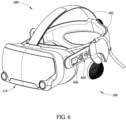
- FIG. 6 shows an exterior 600 of the HMD 100 according to one or more embodiments.
- the HMD 100 includes a set of straps 602 attached to the main body 116.
- the set of straps 602 are useable to selectively and securely mount the HMD 100 to the head of the user 104 for viewing visual content.
- the main body 116 may include a control panel 604 for controlling various aspects of the HMD 100.
- the control panel 604 may include one or more input devices for controlling optical characteristics of the optical system 112 to correct the visual content for vision conditions (e.g ., myopia, hyperopia, astigmatism) of the user 104.
- vision conditions e.g ., myopia, hyperopia, astigmatism
- the input devices may be coupled to the first and second actuators 322 and 324 to respectively control positions of the first lens 304 and the second lens 306 along the first axis 310 and the second axis 312.
- the input devices may be coupled to the first actuator 414 and the second actuator 416 to respectively control angular positions of the first lens 404 and the second lens 406 about the first axis 410 and the second axis 412.
- the input devices may be mechanical devices that are mechanically coupled to and configured to control corresponding lenses.
- the input devices may be knobs or dials that are mechanically linked to actuators of corresponding lenses through, e.g. , gears and shafts. Interaction with the mechanical input devices by the user 104 may cause a mechanical force to be applied to corresponding actuators to adjust the position of a lens.
- the input devices may be electrical devices that are electrically coupled to and configured to control corresponding lenses. As an example, the input devices may, in response to interaction by the user 104, cause an electrical signal to be sent to a controller that, in response, sends a control signal to corresponding actuators to adjust positions of the lenses.
- Non-limiting examples of an electrical input device of the control panel 604 include a keypad having a set of keys for providing alphanumeric input or navigating a menu, or a dial or knob that is electrically coupled to a controller that operates one or more actuators.
- the exterior 600 may include a display 606 for displaying information regarding the HMD 100, such as current optical settings of the optical system 112.
- the display 606 may be a touchscreen input device that the user 104 may interact with to control the optical system 112.
- the user may adjust the optical settings of the optical system 112 in connection with visual content presented by the virtual image display unit(s) 106.
- the user wearing the HMD 100 may interact with the control panel 604 or other input device (e.g. , hand-held controller, mouse, keyboard) according to a menu or other visual content displayed by the virtual image display unit(s) 106 to adjust the optical settings.
- the user may navigate a menu via the control panel 604 or other input device and provide user input that causes the optical settings of the optical system 112 to be changed in response.
- the HMD 100 may adjust the optical settings of the optical system 112 in real-time in response to user input regarding visual content perceived by the user 104.
- the user may initiate a visual test on the HMD 100 causing the virtual image display unit(s) 106 to display visual content, such as test patterns, and prompting the user to provide input regarding clarity of the visual content.
- the HMD 100 may automatically adjust the optical settings of the optical system 112 for improving the clarity of the visual content to improve the user's 104 experience.
- FIG. 7 is a block diagram 700 showing interconnections of various parts of the HMD 100 according to one or more embodiments.
- the HMD 100 includes a controller 702 comprising one or more processors 704 and memory 706 storing a set of instructions that, as a result of execution by the one or more processors 704, cause the HMD 100 to perform one or more operations described herein.
- the memory 706 may include read-only memory (ROM) and random access memory (RAM) and may be in the form of solid-state memory or a hard disk drive, by way of non-limiting illustrative example.
- the HMD 100 also includes a communication interface 708 electrically coupled to the controller 702 for sending and receiving communications with external devices.
- the communication interface 708 may include one or more wireless transceivers, such as Wi-Fi transceivers, cellular transceivers, Bluetooth TM transceivers, etc., that wirelessly send and receive communications to and from external devices, such as a network router or a computing device (e.g., laptop, desktop, tablet, mobile device).
- the communication interface 708 may include a wired communication port, such as a universal serial bus port, a network interface port, or the like, for wired communication with external devices.
- the HMD 100 may include a set of input devices 710 electrically coupled to the controller 702 for providing user input to the HMD 100.
- One or more of the set of input devices 710 may be provided on the exterior 600 of the HMD 100 - for example, as part of the control panel 604.
- the controller 702 may also be electrically coupled to and configured to control the virtual image display units 106 and/or the display 606 if included.
- the controller 702 may include one or more graphics processing units for generating the virtual image light 102 via the virtual image display units 106.
- the controller 702 is electrically coupled to the optical system 112 and configured to control the optical system 112 for adjusting the optical characteristics thereof, as described herein.
- the controller 702 is electrically coupled to and configured to control a first correction portion 712 of the left optical subsystem 130l, a second correction portion 714 of the left optical subsystem 130l, a first correction portion 716 of the right optical subsystem 130r, and a second correction portion 718 of the right optical subsystem 130r.
- the first correction portions 712 and 716 include one of the set of lenses 302 and the set of lenses 402
- the second correction portions 714 and 718 include the other one of the set of lenses 302 and the set of lenses 402.
- the controller 702 is electrically coupled to actuators 720 of the correction portions 712, 714, 716, and 718 to control the positions of the lenses 722 of the optical system 112. Specifically, the controller 702 sends signals (e.g. , control signals) to the actuators 720 causing the actuators 720 to move or rotate the lens 722 coupled thereto. As described above, the positions (e.g., lateral offsets, angular positions ⁇ ) of the lenses 722 may be controlled to modify optical characteristics of the first correction portions 712 and 716 and/or the second correction portions 714 and 718. The controller 702 may send signals to control the optical subsystem 112 in response to receiving input.
- signals e.g. , control signals
- the controller 702 may adjust the optical characteristics of the optical system 112 in response to receiving input provided via the input device(s) 710. As another example, the controller 702 may adjust the optical characteristics of the optical system 112 in response to receiving an input via the communication interface 708.
- the input received by the controller 702 may have a particular format.
- the input may indicate a prescription for the right eye and/or a prescription for the left eye.
- the input may indicate a refractive or spherical power (sometimes denoted as SPH or S), a cylinder power (sometimes denoted as CYL or C), and/or an axis (usually between 0 and 180).
- the input may include input for the left optical subsystem 130l and the right optical subsystem 130r.
- Adjustment of the optical settings of the optical subsystem 112 may be adjusted in real-time through feedback provided by the user 104.
- the controller 702 may initiate a test to determine adjustments to make to the optical settings of the optical system 112.
- the test may involve causing the virtual image display unit(s) 106 to display particular visual content, such as a test pattern or a detailed visual image, and prompting the user to provide feedback via the input device(s) 710 or the control panel 604.
- the user 104 may provide feedback indicating that aspects (e.g. , text, images) of the visual content appear unclear.
- the controller 702 may adjust the optical settings of the optical system 112 and ask the user 104 whether the adjustments improved clarity of the aspects of the visual content. This process may be iterated until the user 104 is satisfied with the clarity of the visual content.
- the test may be performed in response to receiving user input from a user 104 via an input device 710 or the control panel 604.
- Input over the communication interface 708 may be provided by a device (e.g., laptop, desktop, mobile device, controller) as a result of user interaction.
- the computing device may include a set of instructions (e.g. ,. application, program) that the user can interact with to cause the computing device to send communications including information indicating or representative of optical characteristics for modifying the virtual image light 102 to correct for the user's 104 vision conditions.
- the user may enter the input into the input device 710 or the computing device as a prescription provided by a medical professional and may have a predetermined format, as described above.
- the controller 702 may, in response to receiving the input from the input device(s) 710 or the communication interface 708, determine signals to send to the actuators 720.
- One or more of the processors 704, for example, may access a data structure stored in the memory 706 indicating control signals to be sent to corresponding actuators 720.
- the data structure may be an array, lookup table, or other referential structure in which input data is associated with the corresponding output ( i.e., control signal) to be sent to particular actuators 720.
- the controller 702 may store information in the memory 706 indicating a current state of the optical system 112 (e.g., current states of the actuators 720) from which the controller 702 may determine adjustments to the actuators 720 to be made to satisfy the input received.
- a current state of the optical system 112 e.g., current states of the actuators 720
- the HMD 100 may be configured to detect vision conditions of the user's eyes 1051 and 105r and automatically adjust the optical system 112 as a result of the detection.
- the HMD 100 may include one or more sensors 724 that detect information regarding the user's eyes 1051 and 105r and provides measurements to the controller 702, which adjusts the optical system 112 accordingly.
- the HMD 100 may also include one or more lighting elements 726 coupled to the controller 726 for use in connection with the sensor(s) 724 for obtaining information.
- the light emitting element(s) 726 may emit light at an angle and having certain characteristics (e.g. , frequency, intensity) such that the light is reflected and received by the sensor(s) 724.
- the sensor(s) 724 may determine, based on the light detected from the user's eye, information about the user's eyes. As a result of the information determined regarding the user's 104 eyes, the controller 702 may adjust the optical characteristics of the optical system 112 accordingly. Such information may include information indicating a topology of the cornea, which the controller 702 may process to determine control signals to be sent to the actuators 720 for adjusting the optical system 112 so that the user 104 can resolve the virtual image light 102 as clear visual content.
- FIG 8 shows an embodiment of an HMD 800 according to the claimed invention, having an optical subsystem 802 that is selectively installable in and removable from the HMD 800.
- the HMD 800 has a cavity 804, provided between a front portion 806 and a viewing portion 808, sized and shaped to receive the optical subsystem 802.
- the optical system 802 has a body 810 sized and shaped to snuggly fit within the cavity 804.
- the optical system 802 contains the left and right optical subsystems 1301 and 130r ( Figure 1 ) each comprising one or both of the first correction portion 210 and the second correction portion 212 described herein.
- the HMD 800 is configured to securely and selectively retain the optical system 802 upon insertion of the body 810 therein.
- the body 810 may, for instance, have a fastener or other feature 812 that engages with a corresponding feature within the cavity 804 to retain the optical subsystem 112 once inserted in the cavity 804.
- the HMD 800 may, in some implementations, have a set of doors 814 that open to allow insertion of the optical system 804, but which remain closed otherwise to prevent dust and debris from entering the HMD 800.
- a front side 816 of the body 810 includes a receiving portion 202 for receiving virtual image light 102 from the virtual image display units 106, as described above.
- a back side 818 of the body 810 includes left and right emitting portions 206l and 206r for emitting the corrected virtual image light 114 for viewing by the user 104.
- the optical subsystem 812 has one or more electrical contacts 820 exposed on an exterior surface sized and shaped to engage with corresponding electrical contacts within the cavity 804 for establishing an electrical connection through which signals and power may be transmitted to actuators of the optical system 802.
- the optical system 802 may include a controller independent of the controller 702 for sending control signals to the actuators 720.
- the independent controller of the optical system 802 may receive signals or information from the controller 702 or the communication interface 708 and adjust the optical characteristics of the left and right optical subsystems 130l and 130r according to the signals or information received.
- the user 104 may interact with input devices 822 provided on an exterior of the HMD 800 to adjust the optical characteristics, as described above with respect to the control panel 604.
- the optical subsystem 812 may include a mechanical interface (e.g. , dials, knobs) in addition to the electrical contacts 820 for selectively adjusting the optical settings of the left and right optical subsystems 130l and 130r.
- the mechanical interface may be operable by a user to adjust the optical settings.
- the mechanical interface may interface with a corresponding mechanical interface within the cavity 804. The user may interact with the control panel 604 which may cause the corresponding mechanical interface within the cavity to interact with the mechanical interface of the optical system 802 to adjust the optical settings.
Landscapes
- Physics & Mathematics (AREA)
- General Physics & Mathematics (AREA)
- Optics & Photonics (AREA)
- Engineering & Computer Science (AREA)
- Health & Medical Sciences (AREA)
- Ophthalmology & Optometry (AREA)
- Computer Hardware Design (AREA)
- Theoretical Computer Science (AREA)
- General Health & Medical Sciences (AREA)
- Human Computer Interaction (AREA)
- General Engineering & Computer Science (AREA)
- Lenses (AREA)
Claims (14)
- Kopfgetragene Anzeigevorrichtung (100; 800), Folgendes umfassend:einen Rahmen (108), eine Aussparung (804) umfassend;eine virtuelle Bildanzeigevorrichtung (106), die mit dem Rahmen (108) gekoppelt und konfiguriert ist zumErzeugen eines virtuellen Bildlichts (216), um einen Benutzer (104) zu veranlassen, visuelle Inhalte wahrzunehmen; undein optisches System (112), das selektiv entfernbar in der Aussparung (804) des Rahmens (108) einsetzbar ist und, wenn es in der Aussparung (804) eingesetzt ist, das optische System (112) entlang eines optischen Pfades (126) von Strahlen (408) des virtuellen Bildlichtes (216) angeordnet ist, wobei das optische System (112) umfasst:
einen ersten Korrekturabschnitt (212; 712), der ein linkes optisches Teilsystem (130l) und ein rechtes optisches Teilsystem (130r) aufweist, wobei jedes der linken und rechten optischen Teilsysteme (130l, 130r) des ersten Korrekturabschnitts (212; 712) umfasst:einen oder mehrere Aktuatoren (322, 720); undeinen ersten Satz von Linsen (302, 722), die an einer ersten Stelle entlang des optischen Pfades (126) angeordnet sind,und welcher erste optische Eigenschaften aufweist, die einen ersten Satz von Sehschwächen korrigieren, wobei eine erste Linse (304) und/oder eine zweite Linse (306) des ersten Satzes von Linsen (302, 722) selektiv relativ zu der anderen von der ersten Linse (304) und der zweiten Linse (306) des ersten Satzes von Linsen (302, 722) über den einen oder die mehreren Aktuatoren (322, 720) einstellbar ist, entlangeiner ersten Achse (310), die quer zum optischen Pfad (126) verläuft, um die ersten optischen Eigenschaften zu modifizieren; undeinen oder mehrere elektrische Kontakte (820), die an einer Außenfläche des optischen Systems (112) freiliegen, wobei der eine oder die mehreren elektrischen Kontakte (820) so dimensioniert und geformt sind, dass sie mit entsprechenden elektrischen Kontakten innerhalb der Aussparung (804) des Rahmens (108) in Eingriff kommen, um eine elektrische Verbindung herzustellen, über welche Signale und Energie an den einen oder die mehreren Aktuatoren (322, 720) des optischen Systems (112) übertragen werden können. - Kopfgetragene Anzeigevorrichtung (100; 800) nach Anspruch 1, wobei der erste Satz von Sehschwächen mindestens eines von Myopie oder Hypermetropie einschließt.
- Kopfgetragene Anzeigevorrichtung (100; 800) nach Anspruch 1, wobei der eine oder die mehreren Aktuatoren (720) betriebsmäßig mit der ersten und/oder der zweiten Linse (304, 306) des ersten Satzes von Linsen (302) gekoppelt und so konfiguriert sind, dass sie selektiv eine relative Position der ersten Linse (304) relativ zur zweiten Linse (306) entlang der ersten Achse (310) einstellen.
- Kopfgetragene Anzeigevorrichtung (100; 800) nach Anspruch 1, wobei die erste Linse (304) relativ zur zweiten Linse (306) entlang der ersten Achse (310) selektiv einstellbar ist und die zweite Linse (306) relativ zur ersten Linse (304) entlang einer zweiten Achse (312) quer zum optischen Pfad (126) selektiv einstellbar ist, um die ersten optischen Eigenschaften zu modifizieren.
- Kopfgetragene Anzeigevorrichtung (100; 800) nach Anspruch 1, wobei jedes der linken und rechten optischen Teilsysteme (130l, 130r) des ersten Korrekturabschnitts (212; 712) ferner einen zweiten Satz von Linsen (402) einschließt, die an einer zweiten Stelle entlang des optischen Pfades (126) positioniert sind und zweite optische Eigenschaften aufweisen, die einen zweiten Satz von Sehschwächen korrigieren, wobei eine erste Linse (404) und/oder eine zweite Linse (406) des zweiten Satzes von Linsen (402) selektiv relativ zu der anderen von der ersten Linse (404) und der zweiten Linse (406) über den einen oder die mehreren Aktuatoren (720) um eine zweite Achse (410) quer zu der ersten Achse (310) drehbar ist, um die zweiten optischen Eigenschaften zu modifizieren.
- Kopfgetragene Anzeigevorrichtung (100; 800) nach Anspruch 5, wobei der zweite Satz von Sehschwächen Astigmatismus einschließt.
- Kopfgetragene Anzeigevorrichtung (100; 800) nach Anspruch 5, wobei der eine oder die mehreren Aktuatoren (720) Folgendes umfassen:einen ersten Aktuator (322; 324), der betriebsmäßig mit der ersten und/oder der zweiten Linse (304, 306) des ersten Satzes von Linsen (302) gekoppelt und so konfiguriert ist, dass er selektiv eine relative Position der ersten Linse (304) und/oder der zweiten Linse (306) des ersten Satzes von Linsen (302) relativ zu der anderen der ersten Linse (304) und der zweiten Linse (306) des ersten Satzes von Linsen (302) entlang der ersten Achse (310) einstellt;
undeinen zweiten Aktuator (414; 416), der mit der ersten Linse (404) und/oder der zweiten Linse (406) des zweiten Satzes von Linsen (402) gekoppelt und so konfiguriert ist, dass er eine Winkelposition der ersten Linse (404) und/oder der zweiten Linse (406) des zweiten Satzes von Linsen (402) relativ zu der anderen der ersten Linse (404) und der zweiten Linse (406) des zweiten Satzes von Linsen (402) entlang der zweiten Achse (410) selektiv einstellt. - Kopfgetragene Anzeigevorrichtung (100; 800) nach Anspruch 7, ferner Folgendes umfassend:eine Kommunikationsschnittstelle (708), konfiguriert zum Empfangen von Benutzereingaben; undeine Steuerung (702), die elektrisch mit dem ersten Aktuator (322; 324) und dem zweiten Aktuator (414; 416) gekoppelt und so konfiguriert ist, dass sie diese steuert, um die Position der ersten und/oder der zweiten Linse ( 304, 306) des ersten Satzes von Linsen (302) und die Winkelposition der ersten Linse (404) und/oder der zweiten Linse (406) des zweiten Satzes von Linsen (402) basierend auf der Benutzereingabe zu steuern.
- Kopfgetragene Anzeigevorrichtung (100; 800) nach Anspruch 8, wobei die Benutzereingabe eine optische Sehschwäche des Benutzers (104) angibt.
- Kopfgetragene Anzeigevorrichtung (100; 800) nach Anspruch 8, ferner umfassend:
Speicher (706) zum Speichern von Daten, die einen Satz von Einträgen speichern, die jeweils einen Zustand des ersten Aktuators (322; 324) und/oder des zweiten Aktuators (414; 416) anzeigen, wobei die Steuerung (702) ferner so konfiguriert ist, dass sie als Reaktion auf das Empfangen der Benutzereingabe auf einen Eintrag des Satzes von Einträgen basierend auf in der Benutzereingabe spezifizierten Informationen zugreift und den ersten Aktuator (322; 324) oder den zweiten Aktuator (414; 416) entsprechend dem in dem Eintrag angezeigten Zustand steuert. - Kopfgetragene Anzeigevorrichtung (100; 800) nach Anspruch 5, wobei die erste Linse (404) des zweiten Satzes von Linsen (402) selektiv relativ zu der zweiten Linse (406) des zweiten Satzes von Linsen (402) drehbar ist und die zweite Linse (406) des zweiten Satzes von Linsen (402) selektiv relativ zu der ersten Linse (404) des zweiten Satzes von Linsen (402) drehbar ist.
- Kopfgetragene Anzeigevorrichtung (100; 800) nach Anspruch 5, ferner Folgendes umfassend:eine erste Benutzereingabevorrichtung (710; 822), die an einer Außenseite des Rahmens (108) angeordnet ist und von einem Benutzer (104) betätigt werden kann, um selektiv eine Position der mindestens einen der ersten Linse (304) und der zweiten Linse (306) des ersten Satzes von Linsen (302) entlang der ersten Achse (310) einzustellen; undeine zweite Benutzereingabevorrichtung (710; 822), die an der Außenseite des Rahmens (108) angeordnet ist und von dem Benutzer (104) betätigt werden kann, um selektiv eine Winkelposition der mindestens einen der ersten Linse (404) und der zweiten Linse (406) des zweiten Satzes von Linsen (402) entlang der zweiten Achse (410) einzustellen.
- Kopfgetragene Anzeigevorrichtung (100; 800) nach Anspruch 1, wobei das optische System (112) eine Steuerung (702) einschließt, die betriebsbereit ist, um Steuersignale an den einen oder die mehreren Aktoren (720) zu senden.
- Kopfgetragene Anzeigevorrichtung (100; 800) nach Anspruch 1, wobei der erste Satz von Linsen (302) eine oder mehrere Alvarez-Linsen einschließt.
Applications Claiming Priority (2)
| Application Number | Priority Date | Filing Date | Title |
|---|---|---|---|
| US16/676,205 US11391906B2 (en) | 2019-11-06 | 2019-11-06 | Optical system for head-mounted display device |
| PCT/US2020/058831 WO2021091975A1 (en) | 2019-11-06 | 2020-11-04 | Optical system for head-mounted display device |
Publications (3)
| Publication Number | Publication Date |
|---|---|
| EP4055435A1 EP4055435A1 (de) | 2022-09-14 |
| EP4055435A4 EP4055435A4 (de) | 2023-12-27 |
| EP4055435B1 true EP4055435B1 (de) | 2025-03-05 |
Family
ID=75687222
Family Applications (1)
| Application Number | Title | Priority Date | Filing Date |
|---|---|---|---|
| EP20884076.9A Active EP4055435B1 (de) | 2019-11-06 | 2020-11-04 | Optisches system für eine kopfmontierte anzeigevorrichtung |
Country Status (6)
| Country | Link |
|---|---|
| US (1) | US11391906B2 (de) |
| EP (1) | EP4055435B1 (de) |
| JP (1) | JP7601312B2 (de) |
| KR (1) | KR102918353B1 (de) |
| CN (1) | CN114616505B (de) |
| WO (1) | WO2021091975A1 (de) |
Families Citing this family (8)
| Publication number | Priority date | Publication date | Assignee | Title |
|---|---|---|---|---|
| US12032159B2 (en) * | 2021-04-21 | 2024-07-09 | NewSight Reality, Inc. | Optical module having active array of elements capable of synchronizing with see-through display |
| EP4333684A2 (de) | 2021-05-06 | 2024-03-13 | Plenoptika, Inc. | Augenuntersuchungsverfahren und -system |
| US11768375B2 (en) * | 2021-09-03 | 2023-09-26 | Microsoft Technology Licensing, Llc | Control of variable-focus lenses in a mixed-reality device for presbyopes |
| US20240369843A1 (en) * | 2021-09-22 | 2024-11-07 | Apple Inc. | A head mountable device comprising adjustable and modular lenses |
| CN116413911B (zh) * | 2021-12-31 | 2025-08-01 | 北京耐德佳显示技术有限公司 | 一种超薄型镜片、使用其的虚像成像装置和近眼显示器 |
| US20240004199A1 (en) * | 2022-07-01 | 2024-01-04 | Google Llc | Partially curved lightguide with pupil replicators |
| EP4491099A1 (de) | 2023-07-12 | 2025-01-15 | Plenoptika, Inc. | Sehkorrektur fuer intelligente brillen und anpassungsverfahren und -system |
| US20250035953A1 (en) * | 2023-07-24 | 2025-01-30 | Valve Corporation | Diffractive-based optical system for head-mounted display device |
Family Cites Families (12)
| Publication number | Priority date | Publication date | Assignee | Title |
|---|---|---|---|---|
| JPH09261556A (ja) * | 1996-03-21 | 1997-10-03 | Olympus Optical Co Ltd | 頭部装着型映像表示装置 |
| KR20160033926A (ko) * | 2014-09-19 | 2016-03-29 | 엘지전자 주식회사 | 헤드 마운트 디스플레이용 초점 조절 장치 |
| KR102524322B1 (ko) * | 2015-09-25 | 2023-04-24 | 삼성전자주식회사 | 밴드 연결 장치 및 이를 구비한 헤드 마운트 디스플레이 장치 |
| US10241569B2 (en) * | 2015-12-08 | 2019-03-26 | Facebook Technologies, Llc | Focus adjustment method for a virtual reality headset |
| US10108013B2 (en) * | 2016-08-22 | 2018-10-23 | Microsoft Technology Licensing, Llc | Indirect-view augmented reality display system |
| US10373297B2 (en) * | 2016-10-26 | 2019-08-06 | Valve Corporation | Using pupil location to correct optical lens distortion |
| SG11201907370XA (en) * | 2017-02-12 | 2019-09-27 | Lemnis Tech Pte Ltd | Methods, devices and systems for focus adjustment of displays |
| CN110325895B (zh) * | 2017-02-21 | 2022-02-15 | 脸谱科技有限责任公司 | 聚焦调整多平面头戴式显示器 |
| GB201703352D0 (en) * | 2017-03-01 | 2017-04-19 | Adlens Ltd | Improvements in or relating to virtual and augmented reality headsets |
| CN119738966A (zh) * | 2017-05-17 | 2025-04-01 | 苹果公司 | 具有视力矫正的头戴式显示设备 |
| US10663738B2 (en) * | 2017-12-04 | 2020-05-26 | Samsung Electronics Co., Ltd. | System and method for HMD configurable for various mobile device sizes |
| US10782527B2 (en) * | 2017-12-27 | 2020-09-22 | North Inc. | Methods and apparatus to identify lenses of head-wearable apparatus |
-
2019
- 2019-11-06 US US16/676,205 patent/US11391906B2/en active Active
-
2020
- 2020-11-04 CN CN202080075008.8A patent/CN114616505B/zh active Active
- 2020-11-04 EP EP20884076.9A patent/EP4055435B1/de active Active
- 2020-11-04 WO PCT/US2020/058831 patent/WO2021091975A1/en not_active Ceased
- 2020-11-04 JP JP2022520206A patent/JP7601312B2/ja active Active
- 2020-11-04 KR KR1020227018933A patent/KR102918353B1/ko active Active
Also Published As
| Publication number | Publication date |
|---|---|
| JP7601312B2 (ja) | 2024-12-17 |
| CN114616505A (zh) | 2022-06-10 |
| EP4055435A4 (de) | 2023-12-27 |
| KR102918353B1 (ko) | 2026-01-27 |
| US20210132323A1 (en) | 2021-05-06 |
| KR20220093364A (ko) | 2022-07-05 |
| US11391906B2 (en) | 2022-07-19 |
| WO2021091975A1 (en) | 2021-05-14 |
| EP4055435A1 (de) | 2022-09-14 |
| CN114616505B (zh) | 2023-04-25 |
| JP2022553629A (ja) | 2022-12-26 |
Similar Documents
| Publication | Publication Date | Title |
|---|---|---|
| EP4055435B1 (de) | Optisches system für eine kopfmontierte anzeigevorrichtung | |
| US11256092B2 (en) | Binocular wide field of view (WFOV) wearable optical display system | |
| Rolland et al. | Head-mounted display systems | |
| CN113853546B (zh) | 具有能调节瞳距的机构的双目型头戴式显示系统 | |
| JPH03214872A (ja) | 眼鏡型網膜直接表示装置 | |
| US11841507B2 (en) | Viewing field-based optical correction using spatially varying polarizers | |
| JP2025163115A (ja) | 空間変化偏光子を使用した可変光学補正 | |
| US12411342B2 (en) | Head mounted display (HMD) apparatus, method, and system | |
| US20250035953A1 (en) | Diffractive-based optical system for head-mounted display device |
Legal Events
| Date | Code | Title | Description |
|---|---|---|---|
| STAA | Information on the status of an ep patent application or granted ep patent |
Free format text: STATUS: THE INTERNATIONAL PUBLICATION HAS BEEN MADE |
|
| PUAI | Public reference made under article 153(3) epc to a published international application that has entered the european phase |
Free format text: ORIGINAL CODE: 0009012 |
|
| STAA | Information on the status of an ep patent application or granted ep patent |
Free format text: STATUS: REQUEST FOR EXAMINATION WAS MADE |
|
| 17P | Request for examination filed |
Effective date: 20220607 |
|
| AK | Designated contracting states |
Kind code of ref document: A1 Designated state(s): AL AT BE BG CH CY CZ DE DK EE ES FI FR GB GR HR HU IE IS IT LI LT LU LV MC MK MT NL NO PL PT RO RS SE SI SK SM TR |
|
| DAV | Request for validation of the european patent (deleted) | ||
| DAX | Request for extension of the european patent (deleted) | ||
| A4 | Supplementary search report drawn up and despatched |
Effective date: 20231124 |
|
| RIC1 | Information provided on ipc code assigned before grant |
Ipc: G06F 1/16 20060101ALI20231120BHEP Ipc: G02B 3/00 20060101ALI20231120BHEP Ipc: G02C 7/08 20060101ALI20231120BHEP Ipc: G02B 7/09 20210101ALI20231120BHEP Ipc: G02B 7/02 20210101ALI20231120BHEP Ipc: G02B 5/32 20060101ALI20231120BHEP Ipc: G02B 5/30 20060101ALI20231120BHEP Ipc: G02B 27/01 20060101ALI20231120BHEP Ipc: G02B 27/00 20060101AFI20231120BHEP |
|
| GRAP | Despatch of communication of intention to grant a patent |
Free format text: ORIGINAL CODE: EPIDOSNIGR1 |
|
| STAA | Information on the status of an ep patent application or granted ep patent |
Free format text: STATUS: GRANT OF PATENT IS INTENDED |
|
| INTG | Intention to grant announced |
Effective date: 20241004 |
|
| GRAS | Grant fee paid |
Free format text: ORIGINAL CODE: EPIDOSNIGR3 |
|
| GRAA | (expected) grant |
Free format text: ORIGINAL CODE: 0009210 |
|
| STAA | Information on the status of an ep patent application or granted ep patent |
Free format text: STATUS: THE PATENT HAS BEEN GRANTED |
|
| AK | Designated contracting states |
Kind code of ref document: B1 Designated state(s): AL AT BE BG CH CY CZ DE DK EE ES FI FR GB GR HR HU IE IS IT LI LT LU LV MC MK MT NL NO PL PT RO RS SE SI SK SM TR |
|
| P01 | Opt-out of the competence of the unified patent court (upc) registered |
Free format text: CASE NUMBER: APP_4788/2025 Effective date: 20250129 |
|
| REG | Reference to a national code |
Ref country code: GB Ref legal event code: FG4D |
|
| REG | Reference to a national code |
Ref country code: CH Ref legal event code: EP |
|
| REG | Reference to a national code |
Ref country code: IE Ref legal event code: FG4D |
|
| REG | Reference to a national code |
Ref country code: DE Ref legal event code: R096 Ref document number: 602020047418 Country of ref document: DE |
|
| PG25 | Lapsed in a contracting state [announced via postgrant information from national office to epo] |
Ref country code: RS Free format text: LAPSE BECAUSE OF FAILURE TO SUBMIT A TRANSLATION OF THE DESCRIPTION OR TO PAY THE FEE WITHIN THE PRESCRIBED TIME-LIMIT Effective date: 20250605 |
|
| PG25 | Lapsed in a contracting state [announced via postgrant information from national office to epo] |
Ref country code: FI Free format text: LAPSE BECAUSE OF FAILURE TO SUBMIT A TRANSLATION OF THE DESCRIPTION OR TO PAY THE FEE WITHIN THE PRESCRIBED TIME-LIMIT Effective date: 20250305 |
|
| REG | Reference to a national code |
Ref country code: NL Ref legal event code: MP Effective date: 20250305 |
|
| PG25 | Lapsed in a contracting state [announced via postgrant information from national office to epo] |
Ref country code: ES Free format text: LAPSE BECAUSE OF FAILURE TO SUBMIT A TRANSLATION OF THE DESCRIPTION OR TO PAY THE FEE WITHIN THE PRESCRIBED TIME-LIMIT Effective date: 20250305 |
|
| REG | Reference to a national code |
Ref country code: LT Ref legal event code: MG9D |
|
| PG25 | Lapsed in a contracting state [announced via postgrant information from national office to epo] |
Ref country code: NO Free format text: LAPSE BECAUSE OF FAILURE TO SUBMIT A TRANSLATION OF THE DESCRIPTION OR TO PAY THE FEE WITHIN THE PRESCRIBED TIME-LIMIT Effective date: 20250605 |
|
| PG25 | Lapsed in a contracting state [announced via postgrant information from national office to epo] |
Ref country code: HR Free format text: LAPSE BECAUSE OF FAILURE TO SUBMIT A TRANSLATION OF THE DESCRIPTION OR TO PAY THE FEE WITHIN THE PRESCRIBED TIME-LIMIT Effective date: 20250305 |
|
| PG25 | Lapsed in a contracting state [announced via postgrant information from national office to epo] |
Ref country code: LV Free format text: LAPSE BECAUSE OF FAILURE TO SUBMIT A TRANSLATION OF THE DESCRIPTION OR TO PAY THE FEE WITHIN THE PRESCRIBED TIME-LIMIT Effective date: 20250305 |
|
| PG25 | Lapsed in a contracting state [announced via postgrant information from national office to epo] |
Ref country code: GR Free format text: LAPSE BECAUSE OF FAILURE TO SUBMIT A TRANSLATION OF THE DESCRIPTION OR TO PAY THE FEE WITHIN THE PRESCRIBED TIME-LIMIT Effective date: 20250606 Ref country code: BG Free format text: LAPSE BECAUSE OF FAILURE TO SUBMIT A TRANSLATION OF THE DESCRIPTION OR TO PAY THE FEE WITHIN THE PRESCRIBED TIME-LIMIT Effective date: 20250305 |
|
| REG | Reference to a national code |
Ref country code: AT Ref legal event code: MK05 Ref document number: 1773424 Country of ref document: AT Kind code of ref document: T Effective date: 20250305 |
|
| PG25 | Lapsed in a contracting state [announced via postgrant information from national office to epo] |
Ref country code: NL Free format text: LAPSE BECAUSE OF FAILURE TO SUBMIT A TRANSLATION OF THE DESCRIPTION OR TO PAY THE FEE WITHIN THE PRESCRIBED TIME-LIMIT Effective date: 20250305 |
|
| PG25 | Lapsed in a contracting state [announced via postgrant information from national office to epo] |
Ref country code: SE Free format text: LAPSE BECAUSE OF FAILURE TO SUBMIT A TRANSLATION OF THE DESCRIPTION OR TO PAY THE FEE WITHIN THE PRESCRIBED TIME-LIMIT Effective date: 20250305 |
|
| PG25 | Lapsed in a contracting state [announced via postgrant information from national office to epo] |
Ref country code: SM Free format text: LAPSE BECAUSE OF FAILURE TO SUBMIT A TRANSLATION OF THE DESCRIPTION OR TO PAY THE FEE WITHIN THE PRESCRIBED TIME-LIMIT Effective date: 20250305 |
|
| PG25 | Lapsed in a contracting state [announced via postgrant information from national office to epo] |
Ref country code: PT Free format text: LAPSE BECAUSE OF FAILURE TO SUBMIT A TRANSLATION OF THE DESCRIPTION OR TO PAY THE FEE WITHIN THE PRESCRIBED TIME-LIMIT Effective date: 20250707 |
|
| PG25 | Lapsed in a contracting state [announced via postgrant information from national office to epo] |
Ref country code: IT Free format text: LAPSE BECAUSE OF FAILURE TO SUBMIT A TRANSLATION OF THE DESCRIPTION OR TO PAY THE FEE WITHIN THE PRESCRIBED TIME-LIMIT Effective date: 20250305 Ref country code: PL Free format text: LAPSE BECAUSE OF FAILURE TO SUBMIT A TRANSLATION OF THE DESCRIPTION OR TO PAY THE FEE WITHIN THE PRESCRIBED TIME-LIMIT Effective date: 20250305 |
|
| PG25 | Lapsed in a contracting state [announced via postgrant information from national office to epo] |
Ref country code: AT Free format text: LAPSE BECAUSE OF FAILURE TO SUBMIT A TRANSLATION OF THE DESCRIPTION OR TO PAY THE FEE WITHIN THE PRESCRIBED TIME-LIMIT Effective date: 20250305 |
|
| PG25 | Lapsed in a contracting state [announced via postgrant information from national office to epo] |
Ref country code: CZ Free format text: LAPSE BECAUSE OF FAILURE TO SUBMIT A TRANSLATION OF THE DESCRIPTION OR TO PAY THE FEE WITHIN THE PRESCRIBED TIME-LIMIT Effective date: 20250305 Ref country code: EE Free format text: LAPSE BECAUSE OF FAILURE TO SUBMIT A TRANSLATION OF THE DESCRIPTION OR TO PAY THE FEE WITHIN THE PRESCRIBED TIME-LIMIT Effective date: 20250305 |
|
| PG25 | Lapsed in a contracting state [announced via postgrant information from national office to epo] |
Ref country code: RO Free format text: LAPSE BECAUSE OF FAILURE TO SUBMIT A TRANSLATION OF THE DESCRIPTION OR TO PAY THE FEE WITHIN THE PRESCRIBED TIME-LIMIT Effective date: 20250305 |
|
| PG25 | Lapsed in a contracting state [announced via postgrant information from national office to epo] |
Ref country code: SK Free format text: LAPSE BECAUSE OF FAILURE TO SUBMIT A TRANSLATION OF THE DESCRIPTION OR TO PAY THE FEE WITHIN THE PRESCRIBED TIME-LIMIT Effective date: 20250305 |
|
| PG25 | Lapsed in a contracting state [announced via postgrant information from national office to epo] |
Ref country code: IS Free format text: LAPSE BECAUSE OF FAILURE TO SUBMIT A TRANSLATION OF THE DESCRIPTION OR TO PAY THE FEE WITHIN THE PRESCRIBED TIME-LIMIT Effective date: 20250705 |
|
| REG | Reference to a national code |
Ref country code: DE Ref legal event code: R097 Ref document number: 602020047418 Country of ref document: DE |
|
| PGFP | Annual fee paid to national office [announced via postgrant information from national office to epo] |
Ref country code: DE Payment date: 20251128 Year of fee payment: 6 |
|
| PGFP | Annual fee paid to national office [announced via postgrant information from national office to epo] |
Ref country code: GB Payment date: 20251127 Year of fee payment: 6 |
|
| PLBE | No opposition filed within time limit |
Free format text: ORIGINAL CODE: 0009261 |
|
| STAA | Information on the status of an ep patent application or granted ep patent |
Free format text: STATUS: NO OPPOSITION FILED WITHIN TIME LIMIT |
|
| PG25 | Lapsed in a contracting state [announced via postgrant information from national office to epo] |
Ref country code: DK Free format text: LAPSE BECAUSE OF FAILURE TO SUBMIT A TRANSLATION OF THE DESCRIPTION OR TO PAY THE FEE WITHIN THE PRESCRIBED TIME-LIMIT Effective date: 20250305 |
|
| REG | Reference to a national code |
Ref country code: CH Ref legal event code: L10 Free format text: ST27 STATUS EVENT CODE: U-0-0-L10-L00 (AS PROVIDED BY THE NATIONAL OFFICE) Effective date: 20260114 |
|
| PGFP | Annual fee paid to national office [announced via postgrant information from national office to epo] |
Ref country code: FR Payment date: 20251125 Year of fee payment: 6 |
|
| 26N | No opposition filed |
Effective date: 20251208 |