EP4055277B1 - Ejector device - Google Patents
Ejector device Download PDFInfo
- Publication number
- EP4055277B1 EP4055277B1 EP20804634.2A EP20804634A EP4055277B1 EP 4055277 B1 EP4055277 B1 EP 4055277B1 EP 20804634 A EP20804634 A EP 20804634A EP 4055277 B1 EP4055277 B1 EP 4055277B1
- Authority
- EP
- European Patent Office
- Prior art keywords
- nozzle
- diffuser
- housing
- supporting wall
- fluid
- Prior art date
- Legal status (The legal status is an assumption and is not a legal conclusion. Google has not performed a legal analysis and makes no representation as to the accuracy of the status listed.)
- Active
Links
Images





Classifications
-
- F—MECHANICAL ENGINEERING; LIGHTING; HEATING; WEAPONS; BLASTING
- F04—POSITIVE - DISPLACEMENT MACHINES FOR LIQUIDS; PUMPS FOR LIQUIDS OR ELASTIC FLUIDS
- F04F—PUMPING OF FLUID BY DIRECT CONTACT OF ANOTHER FLUID OR BY USING INERTIA OF FLUID TO BE PUMPED; SIPHONS
- F04F5/00—Jet pumps, i.e. devices in which flow is induced by pressure drop caused by velocity of another fluid flow
- F04F5/02—Jet pumps, i.e. devices in which flow is induced by pressure drop caused by velocity of another fluid flow the inducing fluid being liquid
-
- F—MECHANICAL ENGINEERING; LIGHTING; HEATING; WEAPONS; BLASTING
- F04—POSITIVE - DISPLACEMENT MACHINES FOR LIQUIDS; PUMPS FOR LIQUIDS OR ELASTIC FLUIDS
- F04F—PUMPING OF FLUID BY DIRECT CONTACT OF ANOTHER FLUID OR BY USING INERTIA OF FLUID TO BE PUMPED; SIPHONS
- F04F5/00—Jet pumps, i.e. devices in which flow is induced by pressure drop caused by velocity of another fluid flow
- F04F5/02—Jet pumps, i.e. devices in which flow is induced by pressure drop caused by velocity of another fluid flow the inducing fluid being liquid
- F04F5/04—Jet pumps, i.e. devices in which flow is induced by pressure drop caused by velocity of another fluid flow the inducing fluid being liquid displacing elastic fluids
-
- F—MECHANICAL ENGINEERING; LIGHTING; HEATING; WEAPONS; BLASTING
- F04—POSITIVE - DISPLACEMENT MACHINES FOR LIQUIDS; PUMPS FOR LIQUIDS OR ELASTIC FLUIDS
- F04F—PUMPING OF FLUID BY DIRECT CONTACT OF ANOTHER FLUID OR BY USING INERTIA OF FLUID TO BE PUMPED; SIPHONS
- F04F5/00—Jet pumps, i.e. devices in which flow is induced by pressure drop caused by velocity of another fluid flow
- F04F5/02—Jet pumps, i.e. devices in which flow is induced by pressure drop caused by velocity of another fluid flow the inducing fluid being liquid
- F04F5/10—Jet pumps, i.e. devices in which flow is induced by pressure drop caused by velocity of another fluid flow the inducing fluid being liquid displacing liquids, e.g. containing solids, or liquids and elastic fluids
-
- F—MECHANICAL ENGINEERING; LIGHTING; HEATING; WEAPONS; BLASTING
- F04—POSITIVE - DISPLACEMENT MACHINES FOR LIQUIDS; PUMPS FOR LIQUIDS OR ELASTIC FLUIDS
- F04F—PUMPING OF FLUID BY DIRECT CONTACT OF ANOTHER FLUID OR BY USING INERTIA OF FLUID TO BE PUMPED; SIPHONS
- F04F5/00—Jet pumps, i.e. devices in which flow is induced by pressure drop caused by velocity of another fluid flow
- F04F5/14—Jet pumps, i.e. devices in which flow is induced by pressure drop caused by velocity of another fluid flow the inducing fluid being elastic fluid
-
- F—MECHANICAL ENGINEERING; LIGHTING; HEATING; WEAPONS; BLASTING
- F04—POSITIVE - DISPLACEMENT MACHINES FOR LIQUIDS; PUMPS FOR LIQUIDS OR ELASTIC FLUIDS
- F04F—PUMPING OF FLUID BY DIRECT CONTACT OF ANOTHER FLUID OR BY USING INERTIA OF FLUID TO BE PUMPED; SIPHONS
- F04F5/00—Jet pumps, i.e. devices in which flow is induced by pressure drop caused by velocity of another fluid flow
- F04F5/14—Jet pumps, i.e. devices in which flow is induced by pressure drop caused by velocity of another fluid flow the inducing fluid being elastic fluid
- F04F5/16—Jet pumps, i.e. devices in which flow is induced by pressure drop caused by velocity of another fluid flow the inducing fluid being elastic fluid displacing elastic fluids
-
- F—MECHANICAL ENGINEERING; LIGHTING; HEATING; WEAPONS; BLASTING
- F04—POSITIVE - DISPLACEMENT MACHINES FOR LIQUIDS; PUMPS FOR LIQUIDS OR ELASTIC FLUIDS
- F04F—PUMPING OF FLUID BY DIRECT CONTACT OF ANOTHER FLUID OR BY USING INERTIA OF FLUID TO BE PUMPED; SIPHONS
- F04F5/00—Jet pumps, i.e. devices in which flow is induced by pressure drop caused by velocity of another fluid flow
- F04F5/14—Jet pumps, i.e. devices in which flow is induced by pressure drop caused by velocity of another fluid flow the inducing fluid being elastic fluid
- F04F5/24—Jet pumps, i.e. devices in which flow is induced by pressure drop caused by velocity of another fluid flow the inducing fluid being elastic fluid displacing liquids, e.g. containing solids, or liquids and elastic fluids
-
- F—MECHANICAL ENGINEERING; LIGHTING; HEATING; WEAPONS; BLASTING
- F04—POSITIVE - DISPLACEMENT MACHINES FOR LIQUIDS; PUMPS FOR LIQUIDS OR ELASTIC FLUIDS
- F04F—PUMPING OF FLUID BY DIRECT CONTACT OF ANOTHER FLUID OR BY USING INERTIA OF FLUID TO BE PUMPED; SIPHONS
- F04F5/00—Jet pumps, i.e. devices in which flow is induced by pressure drop caused by velocity of another fluid flow
- F04F5/44—Component parts, details, or accessories not provided for in, or of interest apart from, groups F04F5/02 - F04F5/42
-
- F—MECHANICAL ENGINEERING; LIGHTING; HEATING; WEAPONS; BLASTING
- F04—POSITIVE - DISPLACEMENT MACHINES FOR LIQUIDS; PUMPS FOR LIQUIDS OR ELASTIC FLUIDS
- F04F—PUMPING OF FLUID BY DIRECT CONTACT OF ANOTHER FLUID OR BY USING INERTIA OF FLUID TO BE PUMPED; SIPHONS
- F04F5/00—Jet pumps, i.e. devices in which flow is induced by pressure drop caused by velocity of another fluid flow
- F04F5/44—Component parts, details, or accessories not provided for in, or of interest apart from, groups F04F5/02 - F04F5/42
- F04F5/46—Arrangements of nozzles
-
- F—MECHANICAL ENGINEERING; LIGHTING; HEATING; WEAPONS; BLASTING
- F04—POSITIVE - DISPLACEMENT MACHINES FOR LIQUIDS; PUMPS FOR LIQUIDS OR ELASTIC FLUIDS
- F04F—PUMPING OF FLUID BY DIRECT CONTACT OF ANOTHER FLUID OR BY USING INERTIA OF FLUID TO BE PUMPED; SIPHONS
- F04F5/00—Jet pumps, i.e. devices in which flow is induced by pressure drop caused by velocity of another fluid flow
- F04F5/44—Component parts, details, or accessories not provided for in, or of interest apart from, groups F04F5/02 - F04F5/42
- F04F5/46—Arrangements of nozzles
- F04F5/466—Arrangements of nozzles with a plurality of nozzles arranged in parallel
-
- F—MECHANICAL ENGINEERING; LIGHTING; HEATING; WEAPONS; BLASTING
- F04—POSITIVE - DISPLACEMENT MACHINES FOR LIQUIDS; PUMPS FOR LIQUIDS OR ELASTIC FLUIDS
- F04F—PUMPING OF FLUID BY DIRECT CONTACT OF ANOTHER FLUID OR BY USING INERTIA OF FLUID TO BE PUMPED; SIPHONS
- F04F5/00—Jet pumps, i.e. devices in which flow is induced by pressure drop caused by velocity of another fluid flow
- F04F5/14—Jet pumps, i.e. devices in which flow is induced by pressure drop caused by velocity of another fluid flow the inducing fluid being elastic fluid
- F04F5/16—Jet pumps, i.e. devices in which flow is induced by pressure drop caused by velocity of another fluid flow the inducing fluid being elastic fluid displacing elastic fluids
- F04F5/20—Jet pumps, i.e. devices in which flow is induced by pressure drop caused by velocity of another fluid flow the inducing fluid being elastic fluid displacing elastic fluids for evacuating
-
- F—MECHANICAL ENGINEERING; LIGHTING; HEATING; WEAPONS; BLASTING
- F04—POSITIVE - DISPLACEMENT MACHINES FOR LIQUIDS; PUMPS FOR LIQUIDS OR ELASTIC FLUIDS
- F04F—PUMPING OF FLUID BY DIRECT CONTACT OF ANOTHER FLUID OR BY USING INERTIA OF FLUID TO BE PUMPED; SIPHONS
- F04F5/00—Jet pumps, i.e. devices in which flow is induced by pressure drop caused by velocity of another fluid flow
- F04F5/44—Component parts, details, or accessories not provided for in, or of interest apart from, groups F04F5/02 - F04F5/42
- F04F5/46—Arrangements of nozzles
- F04F5/463—Arrangements of nozzles with provisions for mixing
Definitions
- This invention relates to an ejector device
- Ejector devices are known for the pumping of fluids, e.g. liquids or gases. Operation of ejector devices is based upon the venturi principle. Velocity of a relatively high pressure fluid (called the “motive” fluid) along a channel provides a suction effect on a relatively low pressure fluid (called the “entrained” or “suction” fluid). The suction fluid is entrained into the main flow through the channel and ejected from the ejector device as a “discharge” fluid. Examples of such ejector devices which use a motive liquid to pressurise a gas may be called a jet pump, a liquid jet compressor or a Venturi pump.
- Ejector devices have an advantage over many conventional mechanical pumps in that they can have substantially no moving parts, so may therefore provide a longer service life in many practical applications. Ejectors have been used with a combination of different fluids over the years and can be found in a multitude of industries.
- FIG. 1 shows an example of an ejector device described in WO 2012/059773 A2 .
- the ejector device 1 has a motive fluid inlet portion 10 through which a motive fluid can enter the device 1.
- the motive fluid may for example be pumped by a pump (not shown) into and through the motive fluid inlet or injector portion 10.
- the velocity of the motive fluid increases as it passes through a conical nozzle portion 40 of the device 1 before being injected through an outlet aperture 44 of the nozzle portion 40 at an apex thereof into an inlet aperture 52 of a diffuser portion 50.
- the diffuser portion 50 provides a fluid conduit in the form of a Venturi tube, in which, passing from the inlet aperture 52 of the diffuser portion 50 towards an outlet aperture 54 thereof, a diameter of the conduit initially decreases along a first length of the diffuser portion 50 to a diameter less than that of the inlet aperture 52, then remains at that reduced diameter for a short distance, and then along a second length of the diffuser portion 50 the diameter of the conduit increases towards the outlet aperture 54 of the diffuser portion 50.
- the outlet aperture 44 of the nozzle portion 40 and the inlet aperture 52 of the diffuser portion 50 are in fluid communication with a suction fluid inlet portion 20 of the device 1.
- a flow of motive fluid flows out from the outlet aperture 44 of the nozzle portion 40 and into the diffuser portion 50, the motive and suction fluids are mixed, and this results in a transfer of momentum and thus kinetic energy from the motive fluid to the suction fluid.
- This is accompanied by a reduction in the flow velocity of the combined fluids and an increase in the pressure of the suction fluid phase. It is to be noted that this is a reverse process to that occurring in the nozzle portion 40 where an increase in motive fluid velocity occurs, thereby reducing a pressure of the motive fluid as it exits the nozzle portion 40 through its outlet aperture 44.
- the motive fluid may be a liquid or a gas or any other suitable fluid
- the suction fluid may independently also be a liquid or a gas or any other suitable fluid.
- the motive fluid may typically be a liquid phase and the suction fluid may be the gaseous phase to be pumped.
- FIG. 1 shows an example of an ejector device with a single channel, where a "channel" is a combination of a nozzle and a diffuser.
- An ejector device may have multiple channels.
- An example of a multichannel ejector device is described in WO 2012/059773 A2 .
- Ejector devices may be deployed for extended periods, such as a period of years, or tens of years. At some point during deployment it may be necessary to change the internal components of an ejector device to adapt to different operating conditions. For example, consider an ejector device is deployed to pump gas or oil from a well. The pressure of the well changes over a period of time. This may require a different nozzle and/or diffuser to allow the ejector to function at required parameters.
- GB 2 384 027 B describes an ejector with a nozzle and a diffuser which can each, individually, be replaced.
- US 2009/297367 A1 describes an ejector with a housing in tubular form.
- EP 1 064 464 A2 describes an ejector pump.
- US 2015/308461 A1 describes a vacuum ejector with a multinozzle drive stage and booster.
- US 6 276 903 B1 describes a liquid-gas ejector.
- US 2,378,425 A1 describes an ejector condenser.
- US 2017/037874 A1 describes an ejector assembly and vacuum pump.
- US 2,701,681 A describes an ejector condenser with a plurality of columns.
- the nozzle and diffuser assembly may be called a nozzle-diffuser assembly or a nozzle-diffuser channel.
- the connecting structure is configured to concentrically align the nozzle and the diffuser about a longitudinal axis of the nozzle and diffuser assembly.
- the connecting structure is a hollow tubular structure.
- the connecting structure comprises a plurality of apertures around a perimeter of the connecting structure.
- the connecting structure comprises at least one of: (i) a collar free of apertures at an upstream end of the connecting structure; (ii) a collar free of apertures at a downstream end of the connecting structure.
- the collars provide strength to the connecting structure.
- the collars can help to simplify assembly of an overall nozzle and diffuser assembly. This is particularly useful if the connecting structure is manufactured as a separate element to the nozzle and/or the diffuser, as the collar at the upstream end can be aligned with, and connected to, the nozzle and/or the collar at the downstream end can be aligned with, and connected to, the diffuser.
- the diffuser has an inlet with an inlet cross sectional area and the plurality of apertures have a combined aperture cross sectional area, and wherein the combined aperture cross sectional area is equal to, or greater than, the inlet cross sectional area.
- the nozzle and diffuser assembly is removable as a single assembly from one end of the housing.
- the fluid outlet is located at a downstream end of the housing and the nozzle and diffuser assembly is removable from the downstream end of the housing.
- the ejector device comprises at least one sealing element to form a fluid-tight seal between the nozzle and diffuser assembly and an interior of the housing.
- the at least one sealing element is carried by the nozzle and diffuser assembly.
- a downstream end of the nozzle and diffuser assembly comprises a flange which is configured to fit within a recess at a downstream end of the housing.
- a downstream end of the housing has a downstream housing end face and wherein, when the nozzle and diffuser assembly is fitted within the housing, a downstream end face of the nozzle and diffuser assembly is configured to substantially align with the downstream housing end face.
- the first and second supporting walls may substantially seal a volume between the supporting walls, such that fluid entering the volume between the walls via the suction fluid inlet is prevented from passing beyond the walls unless it is drawn into the diffuser via the apertures in the connecting structure.
- the housing has an unobstructed interior volume between the first supporting wall and the second supporting wall.
- the provision of supporting walls, rather than larger supporting structures which extend axially along the housing, has an advantage of reducing an amount of material and therefore weight and cost of the ejector device.
- Providing an unobstructed interior volume between the supporting walls can help to reduce pressure loss between the suction fluid inlet and the diffusers.
- Providing an unobstructed interior volume between the supporting walls can also allow easier cleaning of the interior volume of the housing.
- the ejector device comprises a plate which is configured to fit across a respective downstream end of the plurality of nozzle and diffuser assemblies.
- a downstream end of the housing has a downstream housing end face and wherein, when the plate is fitted to the device, a downstream end face of the plate is configured to substantially align with the downstream housing end face.
- the housing comprises a first housing part and a second housing part, the first housing part configured to connect with the second housing part at a joint to form a fluid-tight housing, wherein the second supporting wall is located at, or upstream of, the joint between the first housing part and the second housing part.
- the suction fluid inlet may be axially aligned with apertures of the connecting structure (or from apertures of the plurality of connecting structures) such that there is a direct radial path between the suction fluid inlet and the apertures.
- the suction fluid inlet is axially offset from apertures of the connecting structure (or from apertures of the plurality of connecting structures where the housing is configured to receive a plurality of the nozzle and diffuser assemblies). This can help improve uniformity of distribution of fluid around the connecting structure or structures. This in turn can improve an efficiency of the ejector device.
- a centreline of the suction fluid inlet may be axially offset from apertures of the connecting structure by at least or substantially 0.5 diameters of the suction fluid inlet, or by at least or substantially one diameter of the suction fluid inlet, or by at least or substantially two diameters of the suction fluid inlet, or by at least or substantially three diameters of the suction fluid inlet.
- An aspect provides a method of maintaining an ejector device according to claim 14.
- the method comprises one of:
- An advantage of this arrangement is that the nozzle can accurately aligned with respect to the diffuser. Alignment of the nozzle with respect to the diffuser is determined during manufacture of the nozzle and diffuser assembly. The term “alignment” refers to the nozzle and the diffuser being aligned concentrically about the same longitudinal axis. This contrasts with prior art ejectors where the nozzle and the diffuser and independently supported by different parts of the ejector, or ejector housing. This means that in prior art systems alignment of the nozzle with respect to the diffuser is determined by features of the housing (e.g. shoulders) in which the nozzle and the diffuser are housed or supported. These features can become deformed or damaged. This can also avoid the need to perform alignment checks on the ejector after installing the nozzle and diffuser assembly.
- An advantage of this arrangement is that a nozzle and diffuser channel of an ejector system can be inspected, maintained or replaced in a reduced time. This reduces time that the ejector is out of operation, and reduces cost of maintenance.
- An advantage of this arrangement is that a nozzle and diffuser channel of an ejector system can be inspected, maintained or replaced by removing a piece of the pipework at a single end of the ejector. For example, by removing pipework at just the downstream end of the ejector. This reduces the number of connections that need to be broken, remade and re-checked for fidelity. During this period the housing remains in situ.
- An advantage of this arrangement is that only one end of the ejector device needs to be provided with features to allow access to the interior of the housing. For example, only one end of the ejector device requires a flanged-connection.
- only a downstream end of the ejector device is provided with a connection to allow access.
- the connecting structure cage is configured such that it has minimal pressure drop on the path to the diffuser, whilst providing a strong and rigid connection that maintains the concentricity of the nozzle and the diffuser.
- the components of the injector portion may be designed with various shapes, configurations and/or orientations which may achieve a particular desirable flow behaviour of generating certain defined components of flow of the motive fluid, as will be discussed further below.
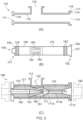
- FIG. 2A-2C show an example of a single-channel ejector device 100.
- the ejector device 100 comprises a housing 110 and a nozzle-diffuser assembly 150.
- FIG. 2A shows the housing 110 of the ejector device.
- FIG. 2B shows the nozzle-diffuser assembly 150.
- FIG. 2C shows the ejector device 100 in assembled form, with the nozzle-diffuser assembly 150 of FIG. 2B fitted within the housing 110 of FIG. 2A .
- the housing 110 comprises a first inlet 111, a second inlet 112 and an outlet 113.
- the first inlet 111 will be called a motive inlet or a high pressure inlet.
- the first inlet 111 is configured to receive a high pressure fluid.
- the first inlet 111 is located at a first, upstream, end of the housing 110.
- the second inlet 112 will be called a suction inlet or a low pressure inlet.
- the second inlet 112 is configured to receive a fluid which is typically at a lower pressure than the pressure received at the first inlet 111.
- the second inlet 112 is located part-way along the housing 110.
- the outlet 113 is configured to output a combination of the fluids received via the first inlet 111 and the second inlet 112.
- the outlet 113 is located at a second, downstream, end of the housing 110.
- the housing 110 is configured to retain the pressures of the fluids the nozzle-diffuser channel is designed to perform over.
- the nozzle-diffuser assembly 150 comprises a nozzle 160 and a diffuser 170 which are connected together by a connecting structure 180.
- the connection is such that the nozzle-diffuser assembly 150 can be inserted, as a single combined assembly, into the housing 110 via a single end of the housing 110.
- the nozzle-diffuser assembly 150 can also be removed, as a single combined assembly, from the housing 110 via the single end of the housing 110.
- the nozzle-diffuser assembly 150 can be inserted via the outlet 113 end of the housing 110.
- the outlet 113 is at a lower pressure than the first inlet 111 and therefore it is easier to provide access at the outlet 113.
- the dimensions of flanges, and the fittings to secure the flanges together, at the outlet 113 are smaller than would be required at the first inlet 111.
- FIG. 2C shows a cross section through the housing 110 and the nozzle-diffuser assembly 150.
- An internal wall 115 of the housing 110 defines a bore. Typically the bore has a circular cross-sectional shape.
- the nozzle-diffuser assembly 150 has an outer diameter which is slightly smaller than a diameter of the internal wall 115.
- the internal wall 115 of the housing 110 may have a substantially constant diameter along its length (i.e. the internal wall is cylindrical). Alternatively, the internal wall 115 of the housing 110 may have a smaller diameter nearer the upstream end (e.g. the internal wall 115 has a tapered shape or the internal wall 115 has a collar of smaller diameter).
- the nozzle-diffuser assembly 150 can move into position with reduced friction between the outer surface of the nozzle-diffuser assembly 150 and the internal wall 115. This can help to reduce wear or damage to any seals, such as O-rings 154, 155.
- the nozzle-diffuser assembly 150 carries O-rings 154, 155 to form a seal against the internal wall 115.
- the O-rings 154, 155 are carried by the nozzle-diffuser assembly 150. This has an advantage of allowing the O-rings to be inspected and/or replaced when the nozzle-diffuser assembly 150 is removed from the housing 110.
- the O-rings 154, 155 may be located within the housing 110.
- the nozzle 160 has a nozzle channel 161.
- the nozzle channel 161 is aligned with a longitudinal axis of the nozzle-diffuser assembly 150.
- a width/diameter of the nozzle channel 161 reduces towards the downstream end (tip) of the nozzle 160.
- This shape of the nozzle channel 161 causes fluid to increase in velocity as it passes towards the downstream end of the nozzle. The increase in velocity is accompanied by a reduction in pressure.
- the outer surface of the nozzle 160 also reduces in width/diameter towards the downstream end of the nozzle. This provides a surface over which suction fluid 122 can flow.
- the diffuser 170 has a diffuser channel 171.
- the diffuser channel 171 varies in width/diameter between an upstream end and a downstream end of the diffuser 170.
- the diffuser channel 171 comprises: a first portion 171A in which the diffuser channel 171 reduces in width/diameter (i.e. a converging portion); a second portion 171B in which the diffuser channel 171 has a substantially constant width/diameter; and a third portion 171C in which the diffuser channel 171 increases in width/diameter (i.e. a diverging portion).
- the relative axial lengths of the first, second and third portions 171A, 171B, 171C can be different to the diffuser shown here.
- the narrowest diameter of the diffuser channel 171 may be different to the diffuser shown here.
- the connecting structure 180 connects the nozzle 160 to the diffuser 170.
- the connecting structure 180 is a hollow tubular structure.
- the connecting structure 180 has a plurality of apertures, or orifices 182, configured to allow fluid to pass into the interior of the connecting structure 180.
- the connecting structure 180 resembles a cage.
- the apertures 182 are distributed around the connecting structure.
- Narrow struts 183 are provided between adjacent apertures 182.
- the tubular structure 180 connects to the nozzle 160 in the region where the outer surface of the nozzle 160 begins to taper.
- the tubular structure 180 connects to the diffuser 170 at the upstream end of the diffuser.
- the outer diameter of the connecting structure 180 is equal, or substantially equal, to the outer diameter of the nozzle 160 and the diffuser 170. In this way, the outer diameter of the nozzle-diffuser assembly is substantially equal along its length.
- the connecting structure 180 axially spaces the outer surface of the nozzle 160 from the diffuser channel 171. In the example shown in FIG. 2C the downstream end of the nozzle 160 is substantially aligned with the upstream end of the diffuser 170, but other arrangements are possible.
- the connecting structure 180 defines a region 181 between the connecting structure 180 and the outer surface of the nozzle 160.
- the hollow tubular structure 180 has a cylindrical wall with apertures 182 in the wall.
- the hollow tubular structure 180 has a cylindrical collar 185 at an upstream end and a cylindrical collar 186 at a downstream end.
- the collars 185, 186 are regions which are free of apertures 182, i.e. regions where there are no apertures 182.
- the collars 185, 186 increase strength of the connecting structure 180.
- the collars 185, 186 can also provide regions for connecting the connecting structure 180 to the nozzle 160 and diffuser 170.
- the collar can provide a surface to weld to the nozzle 160.
- the collar 185 can surround part of the nozzle 160 when the connecting structure is assembled to the nozzle.
- connection between the connecting structure 180 and the nozzle 160 can be achieved by pressing together with a press or interference fit, welding or some other form of connection, such as a screwed fit.
- collar region 185 at the upstream end of the tubular structure 180 can be aligned with and connected to a cylindrical downstream end of the nozzle 160.
- collar region 186 at the downstream end of the tubular structure 180 can be aligned with and connected to a cylindrical upstream end of the diffuser 170.
- the connection between the connecting structure 180 and the diffuser 170 can be achieved by pressing together with a press or interference fit, welding or some other form of connection, such as a screwed fit.
- the connecting structure can be manufactured as a separate element to the nozzle 160 and/or the diffuser 170 and then assembled.
- the collar(s) allow the connecting structure to be aligned with, and connected to, the nozzle 160 and/or the diffuser 170 during assembly.
- the axial length of each of the collars 185, 186 can be different to what is shown in FIG. 2 .
- the nozzle-diffuser assembly 550 shown in FIG. 9 has longer collars 585, 586.
- FIG. 2C shows, in simple terms, fluid flows in the ejector device. It will be understood that the precise path of the fluid flows are more complex than it is possible to show here.
- the shape of the nozzle channel 161 causes a jet of motive fluid to flow from the downstream tip of the nozzle 160. This creates a low pressure region near the tip of the nozzle 160.
- the low pressure region serves to entrain suction fluid via the second inlet 112.
- There is a flow of suction fluid from the second inlet 112 which passes through apertures 182 of the connecting structure 180, into the region 181 between the connecting structure 180 and the outer surface of the nozzle 160.
- Suction fluid is guided by the outer surface of the nozzle 160 towards the low pressure region at the inlet of the diffuser channel 171.
- the motive fluid and suction fluid combine in the diffuser 170.
- the shape of the diffuser channel 171 serves to combine the fluid flows.
- the diffuser channel 171 is narrowing and therefore causes the suction fluid to speed up.
- the diffuser channel 171 is wider than the tip of the nozzle 160 and therefore causes the motive fluid to slow down.
- a combined fluid flow exits the outlet 113 of the ejector device.
- the ejector 100 is fitted within an overall fluid flow system of pipes or conduits.
- Each end of the ejector device 100 has a suitable connector for connecting to a fluid conduit or other fitting or device.
- One type of connector is a flange.
- a pair of fittings are connected together by aligning their respective flanges together and securing the flanges together by bolts or other fixings.
- Other types of connector are possible, suitable for the mechanical design conditions of system the device is connected to.
- the downstream (outlet end) of the housing 110 has a shoulder 114.
- the shoulder 114 is a radially-extending surface, orthogonal to the longitudinal axis of the housing 110.
- the housing continues downstream of the shoulder 114, with a collar 116 having a radial outer surface 117 on the downstream end face.
- the collar 116 and shoulder 114 together define a recess for receiving a downstream end of the nozzle-diffuser assembly 150.
- the nozzle-diffuser assembly 150 has a flange 156 which is configured to locate against the shoulder 114 of the housing 110.
- FIG. 2C shows the flange 156 of the nozzle-diffuser assembly 150 located against the shoulder 114.
- the flange 156 has a diameter which is less than the internal diameter of the collar 116.
- the flange 156 has an axial length which is substantially equal to the axial distance between the shoulder 114 and outer surface 117 of the housing. This allows an outer surface 157 of the flange 156 to lie in the same plane as the radial surface 117 of the housing.
- a flange (or other fitting) can be pressed against the flange 156 and the outer surface 117 of the housing. This provides a surface to connect against, and also securely retains the nozzle-diffuser assembly 150 within the housing 110.
- the arrangement described above provides an end stop for axial movement of the nozzle-diffuser assembly 150.
- the nozzle-diffuser assembly 150 can be inserted into the housing 110 until the flange 156 rests against the shoulder 114 of the housing 110.
- the upstream end of the nozzle-diffuser assembly 150 has an annular radial surface 158.
- An upstream end of the housing 110 has a radial end surface 118. It will be understood that differently shaped surfaces could be provided at the upstream end, such as inclined surfaces.
- axial movement of the nozzle-diffuser assembly 150 is constrained at the upstream end (by radial surface 118) and at the downstream end (by shoulder 114).
- the nozzle-diffuser assembly 150 may be configured to allow for thermal expansion at the upstream end.
- a fitting 190 is connected to the downstream end of the housing 110.
- the fitting 190 is removed from the ejector, such as disconnecting a flange connected to the flange at the downstream end of the housing 110. This provides access to the interior of the housing 110.
- the nozzle-diffuser assembly 150 can then be withdrawn, as a single assembly, from the interior of the housing. Once the nozzle-diffuser assembly 150 has been withdrawn from the housing, it can be inspected (e.g. for routine maintenance, cleaning etc.) and re-inserted into the housing. Alternatively, the nozzle-diffuser assembly 150 which has been withdrawn from the housing may be replaced with a different nozzle-diffuser assembly 150.
- the different nozzle-diffuser assembly 150 may have one or more of: a different nozzle 160 (e.g. a differently shaped or dimensioned nozzle channel 161, a different cross-sectional outlet size at the nozzle tip, a different cross-sectional outlet size at the nozzle inlet, a differently shaped or dimensioned exterior of the nozzle); a different diffuser 170 (e.g. differently shaped or dimensioned diffuser channel 161; different relative dimensions between the portions 171A, 171B, 171C of the diffuser channel); a different spacing between the nozzle and the diffuser.
- the fitting is reconnected to the flange at the downstream end of the housing.
- the nozzle-diffuser assembly 150 may be provided with one or more features to ease withdrawal from the housing. Options include: a lip or ridge that can be gripped with a tool; threaded bores that allow a tool to connect to, and withdraw, the nozzle-diffuser assembly 150.
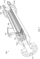
- FIG. 3 shows the connecting structure 180 in more detail.
- the outer surface 165 of the nozzle 160 is visible inside the connecting structure 180.
- the apertures 182 have a generally racetrack shape.
- the apertures 182 are configured to minimise pressure drop of the fluid from the suction inlet 112. This can be achieved by providing a total cross section of all the apertures 182 equal to, or greater than, the cross sectional area of the inlet (i.e. upstream end) of the diffuser 170.
- the number of apertures per connecting structure 180 may be between six and eight, or between six and ten. Other numbers of apertures are possible.
- the struts 183 provide structural support and maintain structural integrity.
- the struts 183 are configured to maintain alignment of the nozzle 160 with respect to the diffuser 170 during use.
- the struts 183 are configured to maintain alignment of the nozzle 160 with respect to the diffuser 170 (i.e. withstand mechanical deformation) during the forces encountered while the nozzle-diffuser assembly 150 is inserted within and/or removed from the housing.
- An upstream end of the connecting structure 180 is connected the nozzle 160.
- the connection can be achieved by pressing together with a press or interference fit, welding or some other form of connection, such as a screwed fit. Another type of connection may be used. A combination of connection types may be used.
- a downstream end of the connecting structure 180 is connected to the diffuser 170. The connection can be achieved by pressing together with a press or interference fit, welding or some other form of connection, such as a screwed fit. Another type of connection may be used. A combination of connection types may be used.
- nozzle-diffuser assembly 150 There are various options for manufacturing and assembling the nozzle-diffuser assembly 150.
- One option is to separately form the nozzle 160, the diffuser 170 and the connecting structure 180 and then to assemble these items together.
- Another option is form two of these as a single item and then assemble to the remaining item (e.g. form the diffuser and the connecting structure as a single item and assemble to the nozzle).
- Another option is to form the nozzle 160, the diffuser 170 and the connecting structure 180 as a single integrated item.
- FIG. 2 the housing 110 has a single suction inlet 112.
- FIG. 4 and FIG. 5 show two alternative arrangements.
- the housing 210 has a first (motive) inlet 211, an outlet 213 and a plurality of second (suction) inlets 212.
- Each suction inlet 212 is defined by a discrete conduit extending outwardly from the housing 210.
- the total number of suction inlets may be more than two.
- the housing 310 has a first (motive) inlet 311, an outlet 313 and a plurality of second (suction) inlets 312.
- the suction inlets 312 are provided as apertures in the wall of the housing 310.
- a distribution chamber (not shown) may surround the plurality of suction inlets 312 and connect to a main suction inlet.
- FIG. 6 shows an example of a multi-channel ejector device 400.
- the ejector device 400 comprises a housing 410 and a plurality of nozzle-diffuser assemblies 450.
- FIG. 6 shows the plurality of nozzle-diffuser assemblies 450 fitted within the housing 410.
- the housing 410 is formed as two housing parts: 410A, 410B. Housing parts 410A, 410B are connected together at a joint or connection 410C. Housing part 410B may be removed from housing part 410A to allow access to the nozzle-diffuser assemblies 450.
- the connection between the housing parts 410A, 410B may be implemented as a pair of flanges and fixings, or by some other type of connection which allows the housing parts to be removed from one another.
- the joint between the housing parts 410A, 410B is capable of forming a fluid-tight seal and may comprise one or more sealing elements.
- the joint between the housing parts 410A, 410B is provided at the downstream end of the housing.
- the housing 410 comprises a first inlet 411, a second inlet 412 and an outlet 413.
- the first (motive) inlet 411 is configured to receive a high pressure fluid.
- the first inlet 411 is located at a first, upstream, end of the housing 410.
- the second (suction) inlet 412 is configured to receive a fluid which is typically at a lower pressure than the pressure received at the first inlet 411.
- the second inlet 412 is located part-way along the housing 410.
- the outlet 413 is configured to output a combination of the fluids received via the first inlet 411 and the second inlet 412.
- the outlet 413 is located at a second, downstream, end of the housing 410.
- the plurality of nozzle-diffuser assemblies 450 are supported within the housing by a pair of supporting walls 421, 422.
- a first supporting wall 421 is provided near the upstream end of the first housing part 410A and a second supporting wall 422 is provided near the downstream end of the first housing part 410A.
- Each of the supporting walls 421, 422 has a plurality of bores for receiving the nozzle-diffuser assemblies 450.
- a nozzle-diffuser assembly 450 is supported by a bore in the supporting wall 421 and by a bore in the supporting wall 422.
- the bores in the supporting wall 421 are shaped to form an end stop.
- the wall 421 has a radial end surface or collar 418.
- the surface 418 serves as an end stop to limit axial movement of the nozzle-diffuser assembly 450 when it is inserted within the housing 410.
- the upstream end of the nozzle-diffuser assembly 450 has an annular radial surface to fit against the end stop. It will be understood that this end stop function could be achieved with differently shaped surface, such as an inclined surface.
- the housing 410 has an unobstructed interior volume between the first supporting wall 421 and the second supporting wall 422. That is, there is no other supporting structure for the nozzle-diffuser assemblies 450. Only the nozzle-diffuser assemblies 450 are positioned within the volume between the supporting walls 421, 422.
- the provision of supporting walls 421, 422, rather than larger supporting structures which extend axially along the housing, has an advantage of reducing an amount of material and therefore weight and cost of the ejector device 400.
- the nozzle 460 and diffuser 470 of each nozzle-diffuser assembly 450 are connected into one integrated assembly, there is no need to provide a longer axial support for the nozzle or the diffuser.
- Providing an unobstructed interior volume between the supporting walls 421, 422 can help to reduce pressure loss between the suction inlet 412 and the diffusers 470.
- the housing 410 can be provided with a drain port 414.
- the drain port 414 is closed by a closure device such as a plug, stopper or tap.
- the drain port 414 can be opened during maintenance or servicing to allow the interior volume of the housing 410 to be drained and cleaned. Providing an unobstructed interior volume between the supporting walls 421, 422 makes it easier to clean the interior volume. By contrast, if each diffuser were supported in a longer axial slot it would be more difficult to clean the interior volume.
- the first housing part 410A increases in width/diameter downstream of the first inlet 411.
- This provides a diverging chamber 431 to distribute the incoming fluid to the respective upstream ends of the plurality of nozzle-diffuser assemblies 450.
- the central portion of the housing 410 has a substantially constant width/diameter.
- the second housing part 410B decreases in width/diameter downstream of the connection 410C. This provides a converging chamber 432 which helps to converge the flows from the plurality of nozzle-diffuser assemblies 450.
- Each of the plurality of nozzle-diffuser assemblies 450 is similar to the nozzle-diffuser assembly 150.
- Each nozzle-diffuser assembly 450 comprises a nozzle 460 and a diffuser 470 which are connected together by a connecting structure 480.
- Each of the nozzle-diffuser assemblies 450 can be inserted, as a single combined assembly, into the housing part 410A via the downstream end of the housing part 410A.
- Each of the nozzle-diffuser assemblies 450 has an outer diameter which is slightly smaller than a diameter of the bore in the supporting walls 421, 422. This allows the nozzle-diffuser assembly 450 to slide into position.
- the nozzle-diffuser assembly 450 carries O-rings to form a seal against the supporting walls 421, 422.
- the connecting structure 480 connects the nozzle 460 to the diffuser 470.
- the connecting structure 480 has a plurality of apertures configured to allow fluid to pass into the interior of the connecting structure 480.
- the connecting structure 480 resembles a cage.
- fluid flows via the suction 412 into the region around the plurality of nozzle-diffuser assemblies 450. Fluid from the suction inlet 412 is distributed between the plurality of nozzle-diffuser assemblies 450 and enters the connecting structures of the nozzle-diffuser assemblies 450.
- the fluid paths shown in FIG. 6 are illustrative. Within the nozzle-diffuser assemblies 450, the process is the same as described above for the nozzle-diffuser assembly 150 and will not be described further.
- Combined fluid i.e. motive fluid and suction fluid
- Combined fluid is output from the downstream ends of the nozzle-diffuser assemblies 450 and converged by the housing before flowing out of the outlet 413.
- FIG. 6 it will be understood that, for each of the individual nozzle-diffuser assemblies 450, the alignment of the nozzle 460 with respect to the diffuser 470 is determined by the assembly 450 itself. This contrasts with conventional multi-channel ejector devices where the alignment of the nozzle with respect to the diffuser is determined by supports within the housing.
- the connecting structures 480 are axially offset along the housing from the suction inlet 412.
- a centreline 412A of the suction inlet 412 is offset from a centreline 482A of the apertures 482 by an axial distance 415.
- This can provide an advantage of maximising the length of the diffuser 470 for a given length of housing. It can also help to allow the fluid arriving via inlet 412 to settle to some extent before entering apertures 482 of one of the nozzle-diffuser assemblies 450.
- the unobstructed interior volume between the supporting walls 421, 422 provides flexibility with nozzle-diffuser assemblies.
- There can be a range of different types of nozzle-diffuser assemblies 450 which are each suited to particular applications. For example, some applications may require a longer diffuser 470 section.
- the different types of nozzle-diffuser assemblies 450 can have apertures 482 positioned at different axial positions, while still being positioned within the unobstructed interior volume.
- each of the individual nozzle-diffuser assemblies 450 is provided with a flange.
- the flange locates within a complementary recess in the supporting wall 422.
- a nozzle-diffuser assembly 450 can be retained within the housing by fixings passing through the flange into the supporting wall 422.
- the second housing part 410B is disconnected from the first housing part 410A at joint 410C at the downstream end of the housing 410. This provides clear access to the interior of the housing, and access to the downstream ends of the plurality of nozzle-diffuser assemblies 450.
- An individual nozzle-diffuser assembly 450 can be removed from the housing by removing fixings securing that individual nozzle-diffuser assembly 450.
- the selected nozzle-diffuser assembly 450 can then be withdrawn, as a single assembly, from the interior of the housing. Once the nozzle-diffuser assembly 450 has been withdrawn from the housing, it can be inspected (e.g.
- the nozzle-diffuser assembly 450 which has been withdrawn from the housing may be replaced with a different nozzle-diffuser assembly 450.
- the nozzle-diffuser assembly 450 is secured by replacing the fixings.
- Other nozzle-diffuser assemblies 450 may be operated upon in the same way.
- the second housing part 410B is reconnected to the first housing part 410A at joint 410C.
- nozzle-diffuser assemblies 450 are supported within the housing 410.
- axial movement of the nozzle-diffuser assembly 450 is constrained at the upstream end (by a radial surface of collar 418) and at the downstream end (by a shoulder in the supporting wall 422).
- the nozzle-diffuser assemblies 450 may be configured to allow for thermal expansion at the upstream end.
- FIGS. 7-10 show another example of a multi-channel ejector device 500.
- the multi-channel ejector device 500 is similar to the multi-channel ejector device 400.
- the multi-channel ejector device 500 has a larger number of nozzle-diffuser assemblies 550 and shows an example of a different configuration at the upstream ends and the downstream ends of the nozzle-diffuser assemblies 550.
- the ejector device 500 comprises a housing 510 and a plurality of nozzle-diffuser assemblies 550.
- FIG. 7 shows the plurality of nozzle-diffuser assemblies 550 fitted within the housing 510.
- FIG. 8 shows a more detailed view of the plurality of nozzle-diffuser assemblies 550 fitted within the housing 510, with a cut-away view of some of the nozzle-diffuser assemblies 550.
- the housing 510 is formed as two housing parts: 510A, 510B. Housing parts 510A, 510B are connected together at a connection 510C. Housing part 510B may be removed from housing part 510B to allow access to the nozzle-diffuser assemblies 550.
- the housing 510 comprises a first inlet 511, a second inlet 512 and an outlet 513.
- the first (motive) inlet 511 is configured to receive a high pressure fluid.
- the first inlet 511 is located at a first, upstream, end of the housing 510.
- the second (suction) inlet 512 is configured to receive a fluid which is typically at a lower pressure than the pressure received at the first inlet 511.
- the second inlet 512 is located part-way along the housing 510.
- the outlet 513 is configured to output a combination of the fluids received via the first inlet 511 and the second inlet 512.
- the outlet 513 is located at a second, downstream, end of the housing 110
- the plurality of nozzle-diffuser assemblies 550 are supported within the housing by a pair of supporting walls 521, 522.
- a first supporting wall 521 is provided near the upstream end of the first housing part 510A and a second supporting wall 522 is provided at the downstream end of the first housing part 510A.
- Each of the supporting walls 521, 522 has a plurality of bores for receiving the nozzle-diffuser assemblies 550.
- a nozzle-diffuser assembly 550 is supported by a bore in the first supporting wall 521 and by a bore in the second supporting wall 522.
- the bores in the first supporting wall 521 may be tapered on their downstream side. This is shown in the detailed view of FIG. 8 .
- the tapering can help to make it easier to insert the nozzle-diffuser assembly 550 into the supporting wall 521.
- the upstream end of a nozzle-diffuser assembly 550 first locates within the wider portion of the tapered bore before being guided into the narrower portion of the bore.
- FIG. 8 and 9 show an example where the nozzle-diffuser assemblies 550 are configured to allow for thermal expansion.
- the upstream end of each of the nozzle-diffuser assemblies 550 locates within a bore in the supporting wall 521.
- the upstream end of each of the nozzle-diffuser assemblies 550 is axially spaced from a constraining surface (e.g. any radial surface or feature). This provides an axial gap to allow for thermal expansion of the nozzle-diffuser assemblies 550.
- the nozzle-diffuser assemblies 550 can safely expand into this gap. This minimises problems which can arise when expansion is constrained, such as distortion of the nozzle-diffuser assemblies or an offset in the angular alignment of the nozzle and the diffuser.
- the nozzle-diffuser assemblies 550 include a deflector vane or blade 565.
- the deflector vanes/blades 565 impart a rotational force to the motive fluid flowing along the nozzle channel 551. These deflector vanes/blades are described in more detail in WO 2018/130818 A1 .
- FIG. 9 shows some detail of a connection between an upstream end of the connecting structure 580 and the nozzle 560.
- the connecting structure 580 has a collar 585 at the upstream end and a collar 586 at the downstream end.
- the collars 585, 586 are regions which are free of apertures 582.
- the collar 585 surrounds a neck portion 562, 563 of the nozzle 560.
- the neck portion 562, 563 has a smaller diameter than the remainder of the nozzle 560 upstream (to the left) of the neck portion.
- the collar 585 of the connecting structure 580 is fitted around the neck portion 562, 563 of the nozzle 560.
- the collar 585 and the neck portion 562, 563 are coaxial.
- the nozzle-diffuser assembly 150 can also use a similar type of connection between the connecting structure 180 and nozzle 160.
- FIG. 10 shows a cross-section through the multi-channel ejector device 500 in the region of the downstream ends of the nozzle-diffuser assemblies 550.
- Each nozzle-diffuser assembly 550 has a flange 556 at the downstream end.
- the flange 556 locates within a recess in the supporting wall 522.
- the nozzle-diffuser assembly 450 can be inserted into the housing until the flange 556 engages with a "stop" defined by a surface of the supporting wall 522.
- a plate 595 extends across the downstream ends of the plurality of nozzle-diffuser assemblies 550.
- the plate 595 has a plurality of apertures 596 which extend through the plate.
- the apertures 596 are located at positions which align with the outlets 553 of the individual nozzle-diffuser assemblies 550.
- the plate 595 has a function of retaining the plurality of nozzle-diffuser assemblies 550. Fixings 525 secure the plate 595 to the supporting wall 522 of the housing. In this example, the plate 595 extends radially beyond the plurality of nozzle-diffuser assemblies 550 and forms part of the flange of the housing.
- an axially-directed force is exerted on the plate 595 which is transmitted to the downstream ends of the nozzle-diffuser assemblies. This reduces stress on the fixings 525.
- the second housing part 510B is disconnected from the first housing part 510A at joint 510C. This provides access to plate 595. Plate 595 is removed. This provides clear access to the downstream ends of the plurality of nozzle-diffuser assemblies 550.
- An individual nozzle-diffuser assembly 550 can be removed from the housing. The selected nozzle-diffuser assembly 550 can then be withdrawn, as a single assembly, from the interior of the housing. Once the nozzle-diffuser assembly 550 has been withdrawn from the housing, it can be inspected (e.g. for routine maintenance, cleaning etc.) and re-inserted into the housing.
- the nozzle-diffuser assembly 550 which has been withdrawn from the housing may be replaced with a different nozzle-diffuser assembly 550.
- Other nozzle-diffuser assemblies 550 may be operated upon in the same way.
- the plate 595 is attached to the first housing part 510A and then the second housing part 510B is reconnected to the first housing part 510A at joint 510C.
- FIG.6 and FIGS. 7-10 comprise a first supporting wall 421, 521 and a second supporting wall 422, 522. It is possible to provide one or more additional supporting walls. More walls is less desirable as it increases the quantity of material required, increases weight and makes it more difficult to insert and withdraw nozzle-diffuser assemblies.
- An ejector of the type described above may be applied in a wide variety of practical applications involving the pumping of a wide variety of "suction" fluids, e.g. gaseous phases, by a wide variety of "motive” fluids, e.g. liquid phases.
- Various forms of gas compression are especially useful applications.
- some practical applications in which ejector devices may be usefully employed may include any of the following:
- any of the following combinations of liquid phase (as the "motive” fluid) and gaseous phase (as the “suction” fluid to be pumped) may be used:
Landscapes
- Engineering & Computer Science (AREA)
- Physics & Mathematics (AREA)
- Fluid Mechanics (AREA)
- Mechanical Engineering (AREA)
- General Engineering & Computer Science (AREA)
- Jet Pumps And Other Pumps (AREA)
Description
- This invention relates to an ejector device
- Ejector devices are known for the pumping of fluids, e.g. liquids or gases. Operation of ejector devices is based upon the venturi principle. Velocity of a relatively high pressure fluid (called the "motive" fluid) along a channel provides a suction effect on a relatively low pressure fluid (called the "entrained" or "suction" fluid). The suction fluid is entrained into the main flow through the channel and ejected from the ejector device as a "discharge" fluid. Examples of such ejector devices which use a motive liquid to pressurise a gas may be called a jet pump, a liquid jet compressor or a Venturi pump.
- Ejector devices have an advantage over many conventional mechanical pumps in that they can have substantially no moving parts, so may therefore provide a longer service life in many practical applications. Ejectors have been used with a combination of different fluids over the years and can be found in a multitude of industries.
-
FIG. 1 shows an example of an ejector device described inWO 2012/059773 A2 . The ejector device 1 has a motivefluid inlet portion 10 through which a motive fluid can enter the device 1. The motive fluid may for example be pumped by a pump (not shown) into and through the motive fluid inlet orinjector portion 10. The velocity of the motive fluid increases as it passes through aconical nozzle portion 40 of the device 1 before being injected through anoutlet aperture 44 of thenozzle portion 40 at an apex thereof into aninlet aperture 52 of adiffuser portion 50. Thediffuser portion 50 provides a fluid conduit in the form of a Venturi tube, in which, passing from theinlet aperture 52 of thediffuser portion 50 towards anoutlet aperture 54 thereof, a diameter of the conduit initially decreases along a first length of thediffuser portion 50 to a diameter less than that of theinlet aperture 52, then remains at that reduced diameter for a short distance, and then along a second length of thediffuser portion 50 the diameter of the conduit increases towards theoutlet aperture 54 of thediffuser portion 50. - The
outlet aperture 44 of thenozzle portion 40 and theinlet aperture 52 of thediffuser portion 50 are in fluid communication with a suctionfluid inlet portion 20 of the device 1. As a flow of motive fluid flows out from theoutlet aperture 44 of thenozzle portion 40 and into thediffuser portion 50, the motive and suction fluids are mixed, and this results in a transfer of momentum and thus kinetic energy from the motive fluid to the suction fluid. This is accompanied by a reduction in the flow velocity of the combined fluids and an increase in the pressure of the suction fluid phase. It is to be noted that this is a reverse process to that occurring in thenozzle portion 40 where an increase in motive fluid velocity occurs, thereby reducing a pressure of the motive fluid as it exits thenozzle portion 40 through itsoutlet aperture 44. - In practical applications of ejectors of the type shown in
FIG. 1 , the motive fluid may be a liquid or a gas or any other suitable fluid, and the suction fluid may independently also be a liquid or a gas or any other suitable fluid. However, in many particularly useful applications such ejector devices may be used to pressurise and thus pump gaseous fluids, in which case the motive fluid may typically be a liquid phase and the suction fluid may be the gaseous phase to be pumped. -
FIG. 1 shows an example of an ejector device with a single channel, where a "channel" is a combination of a nozzle and a diffuser. An ejector device may have multiple channels. An example of a multichannel ejector device is described inWO 2012/059773 A2 . - Ejector devices may be deployed for extended periods, such as a period of years, or tens of years. At some point during deployment it may be necessary to change the internal components of an ejector device to adapt to different operating conditions. For example, consider an ejector device is deployed to pump gas or oil from a well. The pressure of the well changes over a period of time. This may require a different nozzle and/or diffuser to allow the ejector to function at required parameters.
GB 2 384 027 B -
US 2009/297367 A1 describes an ejector with a housing in tubular form.EP 1 064 464 A2 describes an ejector pump.US 2015/308461 A1 describes a vacuum ejector with a multinozzle drive stage and booster.US 6 276 903 B1 describes a liquid-gas ejector.US 2,378,425 A1 describes an ejector condenser.US 2017/037874 A1 describes an ejector assembly and vacuum pump.US 2,701,681 A describes an ejector condenser with a plurality of columns. - There is provided an ejector device according to claim 1.
- The nozzle and diffuser assembly may be called a nozzle-diffuser assembly or a nozzle-diffuser channel.
- Optionally, the connecting structure is configured to concentrically align the nozzle and the diffuser about a longitudinal axis of the nozzle and diffuser assembly.
- Optionally, the connecting structure is a hollow tubular structure.
- Optionally, the connecting structure comprises a plurality of apertures around a perimeter of the connecting structure.
- Optionally, the connecting structure comprises at least one of: (i) a collar free of apertures at an upstream end of the connecting structure; (ii) a collar free of apertures at a downstream end of the connecting structure. The collars provide strength to the connecting structure. The collars can help to simplify assembly of an overall nozzle and diffuser assembly. This is particularly useful if the connecting structure is manufactured as a separate element to the nozzle and/or the diffuser, as the collar at the upstream end can be aligned with, and connected to, the nozzle and/or the collar at the downstream end can be aligned with, and connected to, the diffuser.
- Optionally, the diffuser has an inlet with an inlet cross sectional area and the plurality of apertures have a combined aperture cross sectional area, and wherein the combined aperture cross sectional area is equal to, or greater than, the inlet cross sectional area.
- Optionally, the nozzle and diffuser assembly is removable as a single assembly from one end of the housing.
- Optionally, the fluid outlet is located at a downstream end of the housing and the nozzle and diffuser assembly is removable from the downstream end of the housing.
- Optionally, the ejector device comprises at least one sealing element to form a fluid-tight seal between the nozzle and diffuser assembly and an interior of the housing.
- Optionally, the at least one sealing element is carried by the nozzle and diffuser assembly.
- Optionally, a downstream end of the nozzle and diffuser assembly comprises a flange which is configured to fit within a recess at a downstream end of the housing.
- Optionally, a downstream end of the housing has a downstream housing end face and wherein, when the nozzle and diffuser assembly is fitted within the housing, a downstream end face of the nozzle and diffuser assembly is configured to substantially align with the downstream housing end face.
- The first and second supporting walls may substantially seal a volume between the supporting walls, such that fluid entering the volume between the walls via the suction fluid inlet is prevented from passing beyond the walls unless it is drawn into the diffuser via the apertures in the connecting structure.
- Optionally, the housing has an unobstructed interior volume between the first supporting wall and the second supporting wall. The provision of supporting walls, rather than larger supporting structures which extend axially along the housing, has an advantage of reducing an amount of material and therefore weight and cost of the ejector device. Providing an unobstructed interior volume between the supporting walls can help to reduce pressure loss between the suction fluid inlet and the diffusers. Providing an unobstructed interior volume between the supporting walls can also allow easier cleaning of the interior volume of the housing.
- Optionally, the ejector device comprises a plate which is configured to fit across a respective downstream end of the plurality of nozzle and diffuser assemblies.
- Optionally, a downstream end of the housing has a downstream housing end face and wherein, when the plate is fitted to the device, a downstream end face of the plate is configured to substantially align with the downstream housing end face.
- Optionally, the housing comprises a first housing part and a second housing part, the first housing part configured to connect with the second housing part at a joint to form a fluid-tight housing, wherein the second supporting wall is located at, or upstream of, the joint between the first housing part and the second housing part.
- The suction fluid inlet may be axially aligned with apertures of the connecting structure (or from apertures of the plurality of connecting structures) such that there is a direct radial path between the suction fluid inlet and the apertures. Optionally, the suction fluid inlet is axially offset from apertures of the connecting structure (or from apertures of the plurality of connecting structures where the housing is configured to receive a plurality of the nozzle and diffuser assemblies). This can help improve uniformity of distribution of fluid around the connecting structure or structures. This in turn can improve an efficiency of the ejector device.
- A centreline of the suction fluid inlet may be axially offset from apertures of the connecting structure by at least or substantially 0.5 diameters of the suction fluid inlet, or by at least or substantially one diameter of the suction fluid inlet, or by at least or substantially two diameters of the suction fluid inlet, or by at least or substantially three diameters of the suction fluid inlet.
- An aspect provides a method of maintaining an ejector device according to claim 14.
- Optionally, the method comprises one of:
- re-inserting the nozzle and diffuser assembly into the housing as a single combined assembly;
- inserting a different nozzle and diffuser assembly into the housing as a single combined assembly.
- An advantage of this arrangement is that the nozzle can accurately aligned with respect to the diffuser. Alignment of the nozzle with respect to the diffuser is determined during manufacture of the nozzle and diffuser assembly. The term "alignment" refers to the nozzle and the diffuser being aligned concentrically about the same longitudinal axis. This contrasts with prior art ejectors where the nozzle and the diffuser and independently supported by different parts of the ejector, or ejector housing. This means that in prior art systems alignment of the nozzle with respect to the diffuser is determined by features of the housing (e.g. shoulders) in which the nozzle and the diffuser are housed or supported. These features can become deformed or damaged. This can also avoid the need to perform alignment checks on the ejector after installing the nozzle and diffuser assembly.
- An advantage of this arrangement is that a nozzle and diffuser channel of an ejector system can be inspected, maintained or replaced in a reduced time. This reduces time that the ejector is out of operation, and reduces cost of maintenance.
- An advantage of this arrangement is that a nozzle and diffuser channel of an ejector system can be inspected, maintained or replaced by removing a piece of the pipework at a single end of the ejector. For example, by removing pipework at just the downstream end of the ejector. This reduces the number of connections that need to be broken, remade and re-checked for fidelity. During this period the housing remains in situ.
- An advantage of this arrangement is that only one end of the ejector device needs to be provided with features to allow access to the interior of the housing. For example, only one end of the ejector device requires a flanged-connection. Advantageously, only a downstream end of the ejector device is provided with a connection to allow access. Optionally, the connecting structure cage is configured such that it has minimal pressure drop on the path to the diffuser, whilst providing a strong and rigid connection that maintains the concentricity of the nozzle and the diffuser.
- In implementing some embodiments or examples of the invention, the components of the injector portion may be designed with various shapes, configurations and/or orientations which may achieve a particular desirable flow behaviour of generating certain defined components of flow of the motive fluid, as will be discussed further below.
- Other objects and advantages may be apparent from the further definitions and descriptions which follow below.
- Within the scope of this application it is envisaged and explicitly intended that the various aspects, embodiments, features, examples and alternatives, and in particular any of the variously defined and described individual features thereof, set out in any of the preceding paragraphs, in any part of the following description and/or accompanying drawings, may be taken and implemented independently or in any combination. For example, features described in connection with one particular embodiment or aspect are to be considered as applicable to and utilisable in all embodiments of all aspects, unless expressly stated otherwise or such features are, in such combinations, incompatible. The invention is defined by the appended claims.
- Embodiments of the present invention in its various aspects will now be described, by way of example only, with reference to the accompanying drawings, in which:
-
FIGURE 1 shows a cross sectional view of a known ejector device; -
FIGURE 2A shows a housing for a single-channel ejector device; -
FIGURE 2B shows a nozzle and diffuser assembly for fitting within the housing ofFIGURE 2A ; -
FIGURE 2C shows the nozzle and diffuser assembly ofFIGURE 2B fitted within the housing ofFIGURE 2A ; -
FIGURE 3 shows a connecting structure ofFIGURE 2B in more detail; -
FIGURE 4 shows an alternative inlet arrangement for the housing; -
FIGURE 5 shows another alternative inlet arrangement for the housing; -
FIGURE 6 shows a multi-channel ejector device; -
FIGURE 7 shows another multi-channel ejector device; -
FIGURE 8 shows the multi-channel ejector device ofFIGURE 7 in more detail; -
FIGURE 9 shows a nozzle and diffuser assembly for fitting within the multi-channel ejector device ofFIGURE 7 -
FIGURE 10 shows a downstream end of the multi-channel ejector device ofFIGURE 7 . -
FIG. 2A-2C show an example of a single-channel ejector device 100. Theejector device 100 comprises ahousing 110 and a nozzle-diffuser assembly 150.FIG. 2A shows thehousing 110 of the ejector device.FIG. 2B shows the nozzle-diffuser assembly 150.FIG. 2C shows theejector device 100 in assembled form, with the nozzle-diffuser assembly 150 ofFIG. 2B fitted within thehousing 110 ofFIG. 2A . - The
housing 110 comprises afirst inlet 111, asecond inlet 112 and anoutlet 113. Thefirst inlet 111 will be called a motive inlet or a high pressure inlet. Thefirst inlet 111 is configured to receive a high pressure fluid. Thefirst inlet 111 is located at a first, upstream, end of thehousing 110. Thesecond inlet 112 will be called a suction inlet or a low pressure inlet. Thesecond inlet 112 is configured to receive a fluid which is typically at a lower pressure than the pressure received at thefirst inlet 111. Thesecond inlet 112 is located part-way along thehousing 110. Theoutlet 113 is configured to output a combination of the fluids received via thefirst inlet 111 and thesecond inlet 112. Theoutlet 113 is located at a second, downstream, end of thehousing 110. Thehousing 110 is configured to retain the pressures of the fluids the nozzle-diffuser channel is designed to perform over. - The nozzle-
diffuser assembly 150 comprises anozzle 160 and adiffuser 170 which are connected together by a connectingstructure 180. The connection is such that the nozzle-diffuser assembly 150 can be inserted, as a single combined assembly, into thehousing 110 via a single end of thehousing 110. The nozzle-diffuser assembly 150 can also be removed, as a single combined assembly, from thehousing 110 via the single end of thehousing 110. InFIG. 2 the nozzle-diffuser assembly 150 can be inserted via theoutlet 113 end of thehousing 110. Theoutlet 113 is at a lower pressure than thefirst inlet 111 and therefore it is easier to provide access at theoutlet 113. For example, the dimensions of flanges, and the fittings to secure the flanges together, at theoutlet 113 are smaller than would be required at thefirst inlet 111. -
FIG. 2C shows a cross section through thehousing 110 and the nozzle-diffuser assembly 150. Aninternal wall 115 of thehousing 110 defines a bore. Typically the bore has a circular cross-sectional shape. The nozzle-diffuser assembly 150 has an outer diameter which is slightly smaller than a diameter of theinternal wall 115. Theinternal wall 115 of thehousing 110 may have a substantially constant diameter along its length (i.e. the internal wall is cylindrical). Alternatively, theinternal wall 115 of thehousing 110 may have a smaller diameter nearer the upstream end (e.g. theinternal wall 115 has a tapered shape or theinternal wall 115 has a collar of smaller diameter). This can allow the nozzle-diffuser assembly 150 to move into position with reduced friction between the outer surface of the nozzle-diffuser assembly 150 and theinternal wall 115. This can help to reduce wear or damage to any seals, such as O-rings diffuser assembly 150 carries O-rings internal wall 115. In this example the O-rings diffuser assembly 150. This has an advantage of allowing the O-rings to be inspected and/or replaced when the nozzle-diffuser assembly 150 is removed from thehousing 110. In another example the O-rings housing 110. - The
nozzle 160 has anozzle channel 161. Thenozzle channel 161 is aligned with a longitudinal axis of the nozzle-diffuser assembly 150. A width/diameter of thenozzle channel 161 reduces towards the downstream end (tip) of thenozzle 160. This shape of thenozzle channel 161 causes fluid to increase in velocity as it passes towards the downstream end of the nozzle. The increase in velocity is accompanied by a reduction in pressure. The outer surface of thenozzle 160 also reduces in width/diameter towards the downstream end of the nozzle. This provides a surface over which suction fluid 122 can flow. - The
diffuser 170 has adiffuser channel 171. Thediffuser channel 171 varies in width/diameter between an upstream end and a downstream end of thediffuser 170. InFIG. 2C thediffuser channel 171 comprises: afirst portion 171A in which thediffuser channel 171 reduces in width/diameter (i.e. a converging portion); asecond portion 171B in which thediffuser channel 171 has a substantially constant width/diameter; and athird portion 171C in which thediffuser channel 171 increases in width/diameter (i.e. a diverging portion). Other arrangements are possible. For example, the relative axial lengths of the first, second andthird portions diffuser channel 171 may be different to the diffuser shown here. - The connecting
structure 180 connects thenozzle 160 to thediffuser 170. InFIG. 2 the connectingstructure 180 is a hollow tubular structure. The connectingstructure 180 has a plurality of apertures, ororifices 182, configured to allow fluid to pass into the interior of the connectingstructure 180. The connectingstructure 180 resembles a cage. InFig. 2B theapertures 182 are distributed around the connecting structure.Narrow struts 183 are provided betweenadjacent apertures 182. Thetubular structure 180 connects to thenozzle 160 in the region where the outer surface of thenozzle 160 begins to taper. Thetubular structure 180 connects to thediffuser 170 at the upstream end of the diffuser. The outer diameter of the connectingstructure 180 is equal, or substantially equal, to the outer diameter of thenozzle 160 and thediffuser 170. In this way, the outer diameter of the nozzle-diffuser assembly is substantially equal along its length. The connectingstructure 180 axially spaces the outer surface of thenozzle 160 from thediffuser channel 171. In the example shown inFIG. 2C the downstream end of thenozzle 160 is substantially aligned with the upstream end of thediffuser 170, but other arrangements are possible. The connectingstructure 180 defines aregion 181 between the connectingstructure 180 and the outer surface of thenozzle 160. - In
FIG. 2 the hollowtubular structure 180 has a cylindrical wall withapertures 182 in the wall. The hollowtubular structure 180 has acylindrical collar 185 at an upstream end and acylindrical collar 186 at a downstream end. Thecollars apertures 182, i.e. regions where there are noapertures 182. Thecollars structure 180. Thecollars structure 180 to thenozzle 160 anddiffuser 170. For example, the collar can provide a surface to weld to thenozzle 160. Thecollar 185 can surround part of thenozzle 160 when the connecting structure is assembled to the nozzle. The connection between the connectingstructure 180 and thenozzle 160 can be achieved by pressing together with a press or interference fit, welding or some other form of connection, such as a screwed fit. During assembly,collar region 185 at the upstream end of thetubular structure 180 can be aligned with and connected to a cylindrical downstream end of thenozzle 160. During assembly,collar region 186 at the downstream end of thetubular structure 180 can be aligned with and connected to a cylindrical upstream end of thediffuser 170. The connection between the connectingstructure 180 and thediffuser 170 can be achieved by pressing together with a press or interference fit, welding or some other form of connection, such as a screwed fit. The connecting structure can be manufactured as a separate element to thenozzle 160 and/or thediffuser 170 and then assembled. The collar(s) allow the connecting structure to be aligned with, and connected to, thenozzle 160 and/or thediffuser 170 during assembly. The axial length of each of thecollars FIG. 2 . For example, the nozzle-diffuser assembly 550 shown inFIG. 9 haslonger collars -
FIG. 2C shows, in simple terms, fluid flows in the ejector device. It will be understood that the precise path of the fluid flows are more complex than it is possible to show here. There is aflow 121 of motive fluid from thefirst inlet 111, through thenozzle channel 161 and into thediffuser channel 171. The shape of thenozzle channel 161 causes a jet of motive fluid to flow from the downstream tip of thenozzle 160. This creates a low pressure region near the tip of thenozzle 160. The low pressure region serves to entrain suction fluid via thesecond inlet 112. There is a flow of suction fluid from thesecond inlet 112 which passes throughapertures 182 of the connectingstructure 180, into theregion 181 between the connectingstructure 180 and the outer surface of thenozzle 160. Suction fluid is guided by the outer surface of thenozzle 160 towards the low pressure region at the inlet of thediffuser channel 171. The motive fluid and suction fluid combine in thediffuser 170. The shape of thediffuser channel 171 serves to combine the fluid flows. For the suction fluid, thediffuser channel 171 is narrowing and therefore causes the suction fluid to speed up. For the motive fluid, thediffuser channel 171 is wider than the tip of thenozzle 160 and therefore causes the motive fluid to slow down. A combined fluid flow exits theoutlet 113 of the ejector device. A more detailed description of the operation of a nozzle and a diffuser of an ejector device is available in, for example,GB 2 384 027 A - Typically, the
ejector 100 is fitted within an overall fluid flow system of pipes or conduits. Each end of theejector device 100 has a suitable connector for connecting to a fluid conduit or other fitting or device. One type of connector is a flange. A pair of fittings are connected together by aligning their respective flanges together and securing the flanges together by bolts or other fixings. Other types of connector are possible, suitable for the mechanical design conditions of system the device is connected to. - In
FIG. 2 the downstream (outlet end) of thehousing 110 has ashoulder 114. Theshoulder 114 is a radially-extending surface, orthogonal to the longitudinal axis of thehousing 110. The housing continues downstream of theshoulder 114, with acollar 116 having a radialouter surface 117 on the downstream end face. Thecollar 116 andshoulder 114 together define a recess for receiving a downstream end of the nozzle-diffuser assembly 150. The nozzle-diffuser assembly 150 has aflange 156 which is configured to locate against theshoulder 114 of thehousing 110.FIG. 2C shows theflange 156 of the nozzle-diffuser assembly 150 located against theshoulder 114. Theflange 156 has a diameter which is less than the internal diameter of thecollar 116. Theflange 156 has an axial length which is substantially equal to the axial distance between theshoulder 114 andouter surface 117 of the housing. This allows anouter surface 157 of theflange 156 to lie in the same plane as theradial surface 117 of the housing. A flange (or other fitting) can be pressed against theflange 156 and theouter surface 117 of the housing. This provides a surface to connect against, and also securely retains the nozzle-diffuser assembly 150 within thehousing 110. - The arrangement described above provides an end stop for axial movement of the nozzle-
diffuser assembly 150. The nozzle-diffuser assembly 150 can be inserted into thehousing 110 until theflange 156 rests against theshoulder 114 of thehousing 110. - In
FIG. 2B , the upstream end of the nozzle-diffuser assembly 150 has an annularradial surface 158. An upstream end of thehousing 110 has aradial end surface 118. It will be understood that differently shaped surfaces could be provided at the upstream end, such as inclined surfaces. - In the example shown in
FIG. 2B axial movement of the nozzle-diffuser assembly 150 is constrained at the upstream end (by radial surface 118) and at the downstream end (by shoulder 114). In other examples, the nozzle-diffuser assembly 150 may be configured to allow for thermal expansion at the upstream end. For example, there can be an axial gap between the upstream end of the nozzle-diffuser assembly 150 and a wall of thehousing 110. This can have an advantage of allowing for thermal expansion. - Removal of the nozzle-
diffuser assembly 150 will now be described. InFIG. 2C a fitting 190 is connected to the downstream end of thehousing 110. Firstly, the fitting 190 is removed from the ejector, such as disconnecting a flange connected to the flange at the downstream end of thehousing 110. This provides access to the interior of thehousing 110. The nozzle-diffuser assembly 150 can then be withdrawn, as a single assembly, from the interior of the housing. Once the nozzle-diffuser assembly 150 has been withdrawn from the housing, it can be inspected (e.g. for routine maintenance, cleaning etc.) and re-inserted into the housing. Alternatively, the nozzle-diffuser assembly 150 which has been withdrawn from the housing may be replaced with a different nozzle-diffuser assembly 150. - The different nozzle-
diffuser assembly 150 may have one or more of: a different nozzle 160 (e.g. a differently shaped or dimensionednozzle channel 161, a different cross-sectional outlet size at the nozzle tip, a different cross-sectional outlet size at the nozzle inlet, a differently shaped or dimensioned exterior of the nozzle); a different diffuser 170 (e.g. differently shaped or dimensioneddiffuser channel 161; different relative dimensions between theportions diffuser assembly 150 into the housing, the fitting is reconnected to the flange at the downstream end of the housing. - The nozzle-
diffuser assembly 150 may be provided with one or more features to ease withdrawal from the housing. Options include: a lip or ridge that can be gripped with a tool; threaded bores that allow a tool to connect to, and withdraw, the nozzle-diffuser assembly 150. -
FIG. 3 shows the connectingstructure 180 in more detail. Theouter surface 165 of thenozzle 160 is visible inside the connectingstructure 180. In this example theapertures 182 have a generally racetrack shape. Theapertures 182 are configured to minimise pressure drop of the fluid from thesuction inlet 112. This can be achieved by providing a total cross section of all theapertures 182 equal to, or greater than, the cross sectional area of the inlet (i.e. upstream end) of thediffuser 170. As an example, the number of apertures per connectingstructure 180 may be between six and eight, or between six and ten. Other numbers of apertures are possible. Thestruts 183 provide structural support and maintain structural integrity. For example, thestruts 183 are configured to maintain alignment of thenozzle 160 with respect to thediffuser 170 during use. Thestruts 183 are configured to maintain alignment of thenozzle 160 with respect to the diffuser 170 (i.e. withstand mechanical deformation) during the forces encountered while the nozzle-diffuser assembly 150 is inserted within and/or removed from the housing. - An upstream end of the connecting
structure 180 is connected thenozzle 160. The connection can be achieved by pressing together with a press or interference fit, welding or some other form of connection, such as a screwed fit. Another type of connection may be used. A combination of connection types may be used. A downstream end of the connectingstructure 180 is connected to thediffuser 170. The connection can be achieved by pressing together with a press or interference fit, welding or some other form of connection, such as a screwed fit. Another type of connection may be used. A combination of connection types may be used. - There are various options for manufacturing and assembling the nozzle-
diffuser assembly 150. One option is to separately form thenozzle 160, thediffuser 170 and the connectingstructure 180 and then to assemble these items together. Another option is form two of these as a single item and then assemble to the remaining item (e.g. form the diffuser and the connecting structure as a single item and assemble to the nozzle). Another option is to form thenozzle 160, thediffuser 170 and the connectingstructure 180 as a single integrated item. - In
FIG. 2 thehousing 110 has asingle suction inlet 112.FIG. 4 and FIG. 5 show two alternative arrangements. InFIG. 4 thehousing 210 has a first (motive)inlet 211, anoutlet 213 and a plurality of second (suction)inlets 212. Eachsuction inlet 212 is defined by a discrete conduit extending outwardly from thehousing 210. The total number of suction inlets may be more than two. InFIG. 5 thehousing 310 has a first (motive) inlet 311, anoutlet 313 and a plurality of second (suction)inlets 312. The suction inlets 312 are provided as apertures in the wall of thehousing 310. A distribution chamber (not shown) may surround the plurality ofsuction inlets 312 and connect to a main suction inlet. -
FIG. 6 shows an example of amulti-channel ejector device 400. Theejector device 400 comprises a housing 410 and a plurality of nozzle-diffuser assemblies 450.FIG. 6 shows the plurality of nozzle-diffuser assemblies 450 fitted within the housing 410. - The housing 410 is formed as two housing parts: 410A, 410B.
Housing parts connection 410C.Housing part 410B may be removed fromhousing part 410A to allow access to the nozzle-diffuser assemblies 450. The connection between thehousing parts housing parts housing parts - The housing 410 comprises a
first inlet 411, asecond inlet 412 and anoutlet 413. The first (motive)inlet 411 is configured to receive a high pressure fluid. Thefirst inlet 411 is located at a first, upstream, end of the housing 410. The second (suction)inlet 412 is configured to receive a fluid which is typically at a lower pressure than the pressure received at thefirst inlet 411. Thesecond inlet 412 is located part-way along the housing 410. Theoutlet 413 is configured to output a combination of the fluids received via thefirst inlet 411 and thesecond inlet 412. Theoutlet 413 is located at a second, downstream, end of the housing 410. - The plurality of nozzle-
diffuser assemblies 450 are supported within the housing by a pair of supportingwalls wall 421 is provided near the upstream end of thefirst housing part 410A and a second supportingwall 422 is provided near the downstream end of thefirst housing part 410A. Each of the supportingwalls diffuser assemblies 450. A nozzle-diffuser assembly 450 is supported by a bore in the supportingwall 421 and by a bore in the supportingwall 422. The bores in the supportingwall 421 are shaped to form an end stop. In the example ofFIG. 6 thewall 421 has a radial end surface orcollar 418. Thesurface 418 serves as an end stop to limit axial movement of the nozzle-diffuser assembly 450 when it is inserted within the housing 410. The upstream end of the nozzle-diffuser assembly 450 has an annular radial surface to fit against the end stop. It will be understood that this end stop function could be achieved with differently shaped surface, such as an inclined surface. - In the example of
FIG. 6 the housing 410 has an unobstructed interior volume between the first supportingwall 421 and the second supportingwall 422. That is, there is no other supporting structure for the nozzle-diffuser assemblies 450. Only the nozzle-diffuser assemblies 450 are positioned within the volume between the supportingwalls walls ejector device 400. As thenozzle 460 anddiffuser 470 of each nozzle-diffuser assembly 450 are connected into one integrated assembly, there is no need to provide a longer axial support for the nozzle or the diffuser. Providing an unobstructed interior volume between the supportingwalls suction inlet 412 and thediffusers 470. - The housing 410 can be provided with a
drain port 414. Thedrain port 414 is closed by a closure device such as a plug, stopper or tap. Thedrain port 414 can be opened during maintenance or servicing to allow the interior volume of the housing 410 to be drained and cleaned. Providing an unobstructed interior volume between the supportingwalls - The
first housing part 410A increases in width/diameter downstream of thefirst inlet 411. - This provides a
diverging chamber 431 to distribute the incoming fluid to the respective upstream ends of the plurality of nozzle-diffuser assemblies 450. The central portion of the housing 410 has a substantially constant width/diameter. Thesecond housing part 410B decreases in width/diameter downstream of theconnection 410C. This provides a convergingchamber 432 which helps to converge the flows from the plurality of nozzle-diffuser assemblies 450. - Each of the plurality of nozzle-
diffuser assemblies 450 is similar to the nozzle-diffuser assembly 150. Each nozzle-diffuser assembly 450 comprises anozzle 460 and adiffuser 470 which are connected together by a connectingstructure 480. Each of the nozzle-diffuser assemblies 450 can be inserted, as a single combined assembly, into thehousing part 410A via the downstream end of thehousing part 410A. - Each of the nozzle-
diffuser assemblies 450 has an outer diameter which is slightly smaller than a diameter of the bore in the supportingwalls diffuser assembly 450 to slide into position. The nozzle-diffuser assembly 450 carries O-rings to form a seal against the supportingwalls - The connecting
structure 480 connects thenozzle 460 to thediffuser 470. The connectingstructure 480 has a plurality of apertures configured to allow fluid to pass into the interior of the connectingstructure 480. The connectingstructure 480 resembles a cage. In use, fluid flows via thesuction 412 into the region around the plurality of nozzle-diffuser assemblies 450. Fluid from thesuction inlet 412 is distributed between the plurality of nozzle-diffuser assemblies 450 and enters the connecting structures of the nozzle-diffuser assemblies 450. The fluid paths shown inFIG. 6 are illustrative. Within the nozzle-diffuser assemblies 450, the process is the same as described above for the nozzle-diffuser assembly 150 and will not be described further. Combined fluid (i.e. motive fluid and suction fluid) is output from the downstream ends of the nozzle-diffuser assemblies 450 and converged by the housing before flowing out of theoutlet 413. - In
FIG. 6 it will be understood that, for each of the individual nozzle-diffuser assemblies 450, the alignment of thenozzle 460 with respect to thediffuser 470 is determined by theassembly 450 itself. This contrasts with conventional multi-channel ejector devices where the alignment of the nozzle with respect to the diffuser is determined by supports within the housing. - In
FIG. 6 the connectingstructures 480 are axially offset along the housing from thesuction inlet 412. In this example acentreline 412A of thesuction inlet 412 is offset from acentreline 482A of theapertures 482 by anaxial distance 415. This can provide an advantage of maximising the length of thediffuser 470 for a given length of housing. It can also help to allow the fluid arriving viainlet 412 to settle to some extent before enteringapertures 482 of one of the nozzle-diffuser assemblies 450. The unobstructed interior volume between the supportingwalls diffuser assemblies 450 which are each suited to particular applications. For example, some applications may require alonger diffuser 470 section. The different types of nozzle-diffuser assemblies 450 can haveapertures 482 positioned at different axial positions, while still being positioned within the unobstructed interior volume. - In
FIG. 6 a downstream end of each of the individual nozzle-diffuser assemblies 450 is provided with a flange. The flange locates within a complementary recess in the supportingwall 422. A nozzle-diffuser assembly 450 can be retained within the housing by fixings passing through the flange into the supportingwall 422. - Removal of the nozzle-
diffuser assemblies 450 will now be described. Thesecond housing part 410B is disconnected from thefirst housing part 410A at joint 410C at the downstream end of the housing 410. This provides clear access to the interior of the housing, and access to the downstream ends of the plurality of nozzle-diffuser assemblies 450. An individual nozzle-diffuser assembly 450 can be removed from the housing by removing fixings securing that individual nozzle-diffuser assembly 450. The selected nozzle-diffuser assembly 450 can then be withdrawn, as a single assembly, from the interior of the housing. Once the nozzle-diffuser assembly 450 has been withdrawn from the housing, it can be inspected (e.g. for routine maintenance, cleaning etc.) and re-inserted into the housing. Alternatively, the nozzle-diffuser assembly 450 which has been withdrawn from the housing may be replaced with a different nozzle-diffuser assembly 450. The nozzle-diffuser assembly 450 is secured by replacing the fixings. Other nozzle-diffuser assemblies 450 may be operated upon in the same way. Finally, thesecond housing part 410B is reconnected to thefirst housing part 410A at joint 410C. - Similar to the single channel case of
FIG. 2 , there are some alternatives to how the nozzle-diffuser assemblies 450 are supported within the housing 410. In the example shown inFIG. 6 axial movement of the nozzle-diffuser assembly 450 is constrained at the upstream end (by a radial surface of collar 418) and at the downstream end (by a shoulder in the supporting wall 422). In other examples, the nozzle-diffuser assemblies 450 may be configured to allow for thermal expansion at the upstream end. For example, there can be an axial gap between the upstream end of the nozzle-diffuser assemblies 450 and a constraining surface in supportingwall 421. This can have an advantage of allowing for thermal expansion. -
FIGS. 7-10 show another example of amulti-channel ejector device 500. Themulti-channel ejector device 500 is similar to themulti-channel ejector device 400. Themulti-channel ejector device 500 has a larger number of nozzle-diffuser assemblies 550 and shows an example of a different configuration at the upstream ends and the downstream ends of the nozzle-diffuser assemblies 550. Theejector device 500 comprises a housing 510 and a plurality of nozzle-diffuser assemblies 550.FIG. 7 shows the plurality of nozzle-diffuser assemblies 550 fitted within the housing 510.FIG. 8 shows a more detailed view of the plurality of nozzle-diffuser assemblies 550 fitted within the housing 510, with a cut-away view of some of the nozzle-diffuser assemblies 550. - The housing 510 is formed as two housing parts: 510A, 510B.
Housing parts connection 510C.Housing part 510B may be removed fromhousing part 510B to allow access to the nozzle-diffuser assemblies 550. The housing 510 comprises afirst inlet 511, asecond inlet 512 and anoutlet 513. The first (motive)inlet 511 is configured to receive a high pressure fluid. Thefirst inlet 511 is located at a first, upstream, end of the housing 510. The second (suction)inlet 512 is configured to receive a fluid which is typically at a lower pressure than the pressure received at thefirst inlet 511. Thesecond inlet 512 is located part-way along the housing 510. Theoutlet 513 is configured to output a combination of the fluids received via thefirst inlet 511 and thesecond inlet 512. Theoutlet 513 is located at a second, downstream, end of thehousing 110. - The plurality of nozzle-
diffuser assemblies 550 are supported within the housing by a pair of supportingwalls wall 521 is provided near the upstream end of thefirst housing part 510A and a second supportingwall 522 is provided at the downstream end of thefirst housing part 510A. Each of the supportingwalls diffuser assemblies 550. A nozzle-diffuser assembly 550 is supported by a bore in the first supportingwall 521 and by a bore in the second supportingwall 522. The bores in the first supportingwall 521 may be tapered on their downstream side. This is shown in the detailed view ofFIG. 8 . The tapering can help to make it easier to insert the nozzle-diffuser assembly 550 into the supportingwall 521. The upstream end of a nozzle-diffuser assembly 550 first locates within the wider portion of the tapered bore before being guided into the narrower portion of the bore. -
FIG. 8 and9 show an example where the nozzle-diffuser assemblies 550 are configured to allow for thermal expansion. The upstream end of each of the nozzle-diffuser assemblies 550 locates within a bore in the supportingwall 521. The upstream end of each of the nozzle-diffuser assemblies 550 is axially spaced from a constraining surface (e.g. any radial surface or feature). This provides an axial gap to allow for thermal expansion of the nozzle-diffuser assemblies 550. During operation, the nozzle-diffuser assemblies 550 can safely expand into this gap. This minimises problems which can arise when expansion is constrained, such as distortion of the nozzle-diffuser assemblies or an offset in the angular alignment of the nozzle and the diffuser. - The nozzle-
diffuser assemblies 550 include a deflector vane orblade 565. The deflector vanes/blades 565 impart a rotational force to the motive fluid flowing along the nozzle channel 551. These deflector vanes/blades are described in more detail inWO 2018/130818 A1 . -
FIG. 9 shows some detail of a connection between an upstream end of the connectingstructure 580 and thenozzle 560. The connectingstructure 580 has acollar 585 at the upstream end and acollar 586 at the downstream end. Thecollars apertures 582. Thecollar 585 surrounds aneck portion nozzle 560. In this example, theneck portion nozzle 560 upstream (to the left) of the neck portion. During assembly of the nozzle-diffuser assembly 550, thecollar 585 of the connectingstructure 580 is fitted around theneck portion nozzle 560. Thecollar 585 and theneck portion diffuser assembly 150 can also use a similar type of connection between the connectingstructure 180 andnozzle 160. -
FIG. 10 shows a cross-section through themulti-channel ejector device 500 in the region of the downstream ends of the nozzle-diffuser assemblies 550. Each nozzle-diffuser assembly 550 has aflange 556 at the downstream end. Theflange 556 locates within a recess in the supportingwall 522. The nozzle-diffuser assembly 450 can be inserted into the housing until theflange 556 engages with a "stop" defined by a surface of the supportingwall 522. Aplate 595 extends across the downstream ends of the plurality of nozzle-diffuser assemblies 550. Theplate 595 has a plurality ofapertures 596 which extend through the plate. Theapertures 596 are located at positions which align with theoutlets 553 of the individual nozzle-diffuser assemblies 550. Theplate 595 has a function of retaining the plurality of nozzle-diffuser assemblies 550.Fixings 525 secure theplate 595 to the supportingwall 522 of the housing. In this example, theplate 595 extends radially beyond the plurality of nozzle-diffuser assemblies 550 and forms part of the flange of the housing. When thesecond housing part 510B is coupled to thefirst housing part 510A (as shown inFIG. 10 ), an axially-directed force is exerted on theplate 595 which is transmitted to the downstream ends of the nozzle-diffuser assemblies. This reduces stress on thefixings 525. - Removal of the nozzle-
diffuser assemblies 550 will now be described. Thesecond housing part 510B is disconnected from thefirst housing part 510A at joint 510C. This provides access toplate 595.Plate 595 is removed. This provides clear access to the downstream ends of the plurality of nozzle-diffuser assemblies 550. An individual nozzle-diffuser assembly 550 can be removed from the housing. The selected nozzle-diffuser assembly 550 can then be withdrawn, as a single assembly, from the interior of the housing. Once the nozzle-diffuser assembly 550 has been withdrawn from the housing, it can be inspected (e.g. for routine maintenance, cleaning etc.) and re-inserted into the housing. Alternatively, the nozzle-diffuser assembly 550 which has been withdrawn from the housing may be replaced with a different nozzle-diffuser assembly 550. Other nozzle-diffuser assemblies 550 may be operated upon in the same way. Finally, theplate 595 is attached to thefirst housing part 510A and then thesecond housing part 510B is reconnected to thefirst housing part 510A at joint 510C. - The multiple-channel examples of
FIG.6 andFIGS. 7-10 comprise a first supportingwall wall - An ejector of the type described above may be applied in a wide variety of practical applications involving the pumping of a wide variety of "suction" fluids, e.g. gaseous phases, by a wide variety of "motive" fluids, e.g. liquid phases. Various forms of gas compression are especially useful applications. By way of non-limiting examples, some practical applications in which ejector devices may be usefully employed may include any of the following:
- (i) Water treatment applications:
- entraining ozone, chlorine or other disinfectant gas for disinfection of water used for e.g. swimming pools, cooling towers, bottling plants, etc;
- entraining atmospheric air for transferring oxygen to remove irons and manganese from borehole water;
- entraining atmospheric air for filtering backwashing and/or scouring of filter media.
- (ii) Oil and gas industry applications:
- entraining vent gas;
- de-aeration of seawater;
- entraining header gas for oil/water separation;
- flare gas recovery.
- (iii) Effluent treatment applications:
- entraining atmospheric air for transferring oxygen for sewage treatment;
- entraining atmospheric air for transferring oxygen for chemical oxidising purposes;
- entraining atmospheric air for aerating and mixing balance tanks;
- entraining pressurised air for producing "white water" on DAF (dissolved air flotation) plants.
- (iv) Process applications:
- entraining CO2 for carbonating soft drinks;
- simultaneous scrubbing and pumping of corrosive gases;
- scrubbing and neutralising of sour gas (e.g. using amines);
- recycling and mixing off-gas with motive liquor for increasing contact time and thus enhancing process reactions.
- Other practical applications for particular embodiments or examples, in addition to those exemplified above, may also be available.
- Thus, in some non-limiting practical examples of the use of ejector devices according to embodiments, any of the following combinations of liquid phase (as the "motive" fluid) and gaseous phase (as the "suction" fluid to be pumped) may be used:
- (a) sea water - hydrocarbon(s) (gaseous; single or mixtures thereof);
- (b) produced water - hydrocarbon(s) (gaseous; single or mixtures thereof);
- (c) water - chlorine;
- (d) water - ozone;
- (e) water - air;
- (f) corn syrup - CO2;
- (g) amine(s) - CO2;
- (h) amine(s) - hydrocarbon(s) (gaseous; single or mixtures thereof);
- (i) amines(s) - sour gas;
- (j) sewage - air;
- It is to be understood that the above description of various specific embodiments has been by way of non-limiting examples only, and various modifications may be made from what has been specifically described and illustrated whilst remaining within the scope of the invention as defined by the appended claims.
- Throughout the description and claims of this specification, the words "comprise" and "contain" and linguistic variations of those words, for example "comprising" and "comprises", mean "including but not limited to", and are not intended to (and do not) exclude other moieties, additives, components, integers or steps.
- Throughout the description and claims of this specification, the singular encompasses the plural unless the context otherwise requires. In particular, where the indefinite article is used, the specification is to be understood as contemplating plurality as well as singularity, unless the context requires otherwise.
- Features, integers, characteristics, compounds, chemical moieties or groups described in conjunction with a particular aspect, embodiment or example are to be understood to be applicable to any other aspect, embodiment or example described herein unless incompatible therewith.
Claims (15)
- An ejector device (400, 500) comprising:a housing (410A, 410B, 410C, 510A, 510B, 510C) having a motive fluid inlet (411, 511) to receive motive fluid, a suction fluid inlet (412, 512) to receive suction fluid and a fluid outlet (413, 513) to output the motive fluid and the suction fluida plurality of nozzle and diffuser assemblies (450, 550) configured to fit within the housing wherein each of the nozzle and diffuser assemblies comprises:a nozzle (160);a diffuser (170)a connecting structure (180) connecting the nozzle to the diffuser, the connecting structure configured to permit fluid flow between the nozzle and the diffuser, the connecting structure having apertures (182, 482, 582) configured to allow fluid to be drawn into the fluid flow between the nozzle and the diffuser;wherein the housing comprises a first supporting wall (421, 521) and a second supporting wall (422, 522),wherein each of the first supporting wall and the second supporting wall extends radially across an interior of the housing, the first supporting wall and the second supporting wall axially spaced apart along the housing, each of the first supporting wall and the second supporting wall having a plurality of bores to receive the plurality of the nozzle and diffuser assemblies, wherein the nozzle and diffuser assemblies are individually removable from a downstream end of the housing,characterized in that an upstream end of each of the plurality of nozzle and diffuser assemblies is axially spaced from a constraining radial surface of the first supporting wall (421, 521) of the housing to allow for thermal expansion of the nozzle and diffuser assemblies.
- An ejector device according to claim 1 wherein the connecting structure is configured to concentrically align the nozzle and the diffuser about a longitudinal axis of the nozzle and diffuser assembly.
- An ejector device according to claim 1 or 2 wherein the connecting structure is a hollow tubular structure.
- An ejector device according to any one of the preceding claims wherein the connecting structure comprises a plurality of apertures around a perimeter of the connecting structure.
- An ejector device according to claim 4 wherein the diffuser has an inlet with an inlet cross sectional area and the plurality of apertures have a combined aperture cross sectional area, and wherein the combined aperture cross sectional area is equal to, or greater than, the inlet cross sectional area.
- An ejector device according to any one of the preceding claims wherein the connecting structure comprises at least one of: (i) a collar (185, 585) free of apertures at an upstream end of the connecting structure; (ii) a collar (186, 586) free of apertures at a downstream end of the connecting structure.
- An ejector device according to any one of the preceding claims comprising at least one sealing element (154, 155, 454, 455, 554, 555) to form a fluid-tight seal between the nozzle and diffuser assembly and an interior of the housing.
- An ejector device according to claim 7 wherein the at least one sealing element is carried by the nozzle and diffuser assembly.
- An ejector device according to any one of the preceding claims comprising a plate (595) which is configured to fit across a respective downstream end of the plurality of nozzle and diffuser assemblies.
- An ejector device according to claim 9 wherein a downstream end of the housing has a downstream housing end face and wherein, when the plate is fitted to the device, a downstream end face of the plate is configured to substantially align with the downstream housing end face.
- An ejector device according to any one of the preceding claims wherein the suction fluid inlet is axially offset from apertures of the connecting structures of the plurality of nozzle and diffuser assemblies.
- An ejector device according to any one of the preceding claims wherein the housing has an unobstructed interior volume between the first supporting wall and the second supporting wall.
- An ejector device according to any one of the preceding claims wherein the housing comprises a first housing part and a second housing part, the first housing part configured to connect with the second housing part at a joint to form a fluid-tight housing, wherein the second supporting wall is located at, or upstream of, the joint between the first housing part and the second housing part.
- A method of maintaining an ejector device (400, 500) comprising:accessing an interior of a housing (410A, 410B, 410C, 510A, 510B, 510C) of the ejector device, the housing having a motive fluid inlet (411, 511) to receive motive fluid, a suction fluid inlet (412, 512) to receive suction fluid and a fluid outlet (413, 513) to output the motive fluid and the suction fluid, the housing comprising a first supporting wall (421, 521) and a second supporting wall (422, 522),wherein each of the first supporting wall and the second supporting wall extends radially across an interior of the housing, the first supporting wall and the second supporting wall axially spaced apart along the housing, each of the first supporting wall and the second supporting wall having a plurality of bores to receive a plurality of nozzle and diffuser assemblies, wherein an upstream end of each of the plurality of nozzle and diffuser assemblies is axially spaced from a constraining radial surface of the first supporting wall (421, 521) of the housing to allow for thermal expansion of the nozzle and diffuser assemblies andremoving a nozzle and diffuser assembly from a downstream end of the housing as a single combined assembly, the nozzle and diffuser assembly comprising: a nozzle (160); a diffuser (170); a connecting structure (180) connecting the nozzle to the diffuser, the connecting structure configured to permit fluid flow between the nozzle and the diffuser, the connecting structure having apertures (182, 482, 582) configured to allow fluid to be drawn into the fluid flow between the nozzle and the diffuser.
- A method according to claim 14 comprising one of:re-inserting the nozzle and diffuser assembly into the housing as a single combined assembly;inserting a different nozzle and diffuser assembly into the housing as a single combined assembly.
Applications Claiming Priority (2)
| Application Number | Priority Date | Filing Date | Title |
|---|---|---|---|
| GBGB1916064.7A GB201916064D0 (en) | 2019-11-05 | 2019-11-05 | Ejector device |
| PCT/GB2020/052796 WO2021090004A1 (en) | 2019-11-05 | 2020-11-05 | Ejector device |
Publications (4)
| Publication Number | Publication Date |
|---|---|
| EP4055277A1 EP4055277A1 (en) | 2022-09-14 |
| EP4055277C0 EP4055277C0 (en) | 2024-10-09 |
| EP4055277B1 true EP4055277B1 (en) | 2024-10-09 |
| EP4055277B8 EP4055277B8 (en) | 2024-11-13 |
Family
ID=69059029
Family Applications (1)
| Application Number | Title | Priority Date | Filing Date |
|---|---|---|---|
| EP20804634.2A Active EP4055277B8 (en) | 2019-11-05 | 2020-11-05 | Ejector device |
Country Status (4)
| Country | Link |
|---|---|
| US (1) | US12281660B2 (en) |
| EP (1) | EP4055277B8 (en) |
| GB (2) | GB201916064D0 (en) |
| WO (1) | WO2021090004A1 (en) |
Families Citing this family (4)
| Publication number | Priority date | Publication date | Assignee | Title |
|---|---|---|---|---|
| GB201916064D0 (en) | 2019-11-05 | 2019-12-18 | Transvac Systems Ltd | Ejector device |
| CN113550760B (en) * | 2021-07-26 | 2022-11-25 | 中国铁建重工集团股份有限公司 | Slag discharging device |
| CN118524942A (en) * | 2021-12-17 | 2024-08-20 | 艾威普科公司 | Non-electromechanical pumpless liquid recirculation system for adiabatic pre-cooling systems for air cooled condensers and coolers |
| CN114294270B (en) * | 2021-12-31 | 2023-08-22 | 大福泵业有限公司 | Jet pump for enhancing mixing degree |
Citations (1)
| Publication number | Priority date | Publication date | Assignee | Title |
|---|---|---|---|---|
| EP1064464B1 (en) * | 1998-03-20 | 2004-11-03 | Xerex Ab | Vacuum ejector pump |
Family Cites Families (14)
| Publication number | Priority date | Publication date | Assignee | Title |
|---|---|---|---|---|
| US2378425A (en) | 1938-02-22 | 1945-06-19 | Murray Henry Lamont | Ejector-condenser |
| US2582069A (en) * | 1945-08-21 | 1952-01-08 | Leigh L Rose | Jet pump |
| US2701681A (en) | 1948-08-25 | 1955-02-08 | Murray Deodorisers Ltd | Ejector condenser |
| RU2133882C1 (en) * | 1998-01-27 | 1999-07-27 | Попов Сергей Анатольевич | Liquid-and-gas ejector |
| GB2384027B (en) | 2002-01-11 | 2006-04-12 | Transvac Systems Ltd | Ejector |
| SG157325A1 (en) * | 2008-05-29 | 2009-12-29 | Denso Corp | Ejector and manufacturing method thereof |
| GB201018721D0 (en) | 2010-11-05 | 2010-12-22 | Transvac Systems Ltd | Improved ejector and method |
| GB2492153A (en) * | 2011-06-23 | 2012-12-26 | Caltec Ltd | Multiple parallel jet pump apparatus |
| GB2509182A (en) | 2012-12-21 | 2014-06-25 | Xerex Ab | Vacuum ejector with multi-nozzle drive stage and booster |
| GB2509184A (en) | 2012-12-21 | 2014-06-25 | Xerex Ab | Multi-stage vacuum ejector with moulded nozzle having integral valve elements |
| GB2524499B (en) | 2014-03-24 | 2020-02-12 | Caltec Ltd | Jet pump |
| KR101472503B1 (en) * | 2014-04-24 | 2014-12-12 | 한국뉴매틱(주) | Ejector assembly and Vaccum pump having the same |
| GB2558627B (en) | 2017-01-11 | 2020-02-26 | Transvac Systems Ltd | Ejector device |
| GB201916064D0 (en) | 2019-11-05 | 2019-12-18 | Transvac Systems Ltd | Ejector device |
-
2019
- 2019-11-05 GB GBGB1916064.7A patent/GB201916064D0/en not_active Ceased
-
2020
- 2020-11-05 WO PCT/GB2020/052796 patent/WO2021090004A1/en not_active Ceased
- 2020-11-05 GB GB2017485.0A patent/GB2590183B/en active Active
- 2020-11-05 EP EP20804634.2A patent/EP4055277B8/en active Active
- 2020-11-05 US US17/772,315 patent/US12281660B2/en active Active
Patent Citations (1)
| Publication number | Priority date | Publication date | Assignee | Title |
|---|---|---|---|---|
| EP1064464B1 (en) * | 1998-03-20 | 2004-11-03 | Xerex Ab | Vacuum ejector pump |
Also Published As
| Publication number | Publication date |
|---|---|
| EP4055277A1 (en) | 2022-09-14 |
| EP4055277C0 (en) | 2024-10-09 |
| EP4055277B8 (en) | 2024-11-13 |
| GB202017485D0 (en) | 2020-12-16 |
| GB2590183B (en) | 2023-03-15 |
| GB2590183A (en) | 2021-06-23 |
| GB201916064D0 (en) | 2019-12-18 |
| WO2021090004A1 (en) | 2021-05-14 |
| US20220364577A1 (en) | 2022-11-17 |
| US12281660B2 (en) | 2025-04-22 |
Similar Documents
| Publication | Publication Date | Title |
|---|---|---|
| US12281660B2 (en) | Ejector device | |
| CN100475319C (en) | Pressure vessels for holding cylindrical filtration cartridges | |
| EP2540387B1 (en) | In-line fluid mixing device | |
| CN106122120B (en) | Compound two-stage multichannel gas-liquid jet pump | |
| US7726870B1 (en) | Method for mixing fluids with an eductor | |
| WO1999061142A1 (en) | Differential injector | |
| US20150292524A1 (en) | Jet pump | |
| EP3568599B1 (en) | Ejector device | |
| US20100150742A1 (en) | Reconfigurable jet pump | |
| US20180162757A1 (en) | Venturi apparatus and method of use | |
| WO2018148305A1 (en) | Improved venturi apparatus and method of use | |
| AU2020314212B2 (en) | Apparatus for dissolving gas into a liquid and method for producing the same | |
| RU2076250C1 (en) | Vortex jet apparatus | |
| US20120308407A1 (en) | Dual injection airlift pump | |
| CN111936224B (en) | Equipment and arrangements for introducing gases into the primary medium, especially in wastewater treatment | |
| RU2072454C1 (en) | Liquid-gas ejector | |
| RU2180711C1 (en) | Multi-stage jet apparatus | |
| CN205977827U (en) | Composite two-stage multi-channel gas-liquid jet pump | |
| KR20230017824A (en) | Reactor sparger assembly | |
| GB2536291A (en) | Jet pump | |
| US10226746B2 (en) | Removable nozzle assembly and gas transfer system | |
| RU2133884C1 (en) | Liquid-and-gas ejector (versions) | |
| JP2004298793A (en) | Ejector and deaeration apparatus using the same | |
| CN215592745U (en) | Split type coupling distribution jet aerator | |
| WO2004055383A1 (en) | Operating method for a well pulse ejection pumping device and device for carrying out said method |
Legal Events
| Date | Code | Title | Description |
|---|---|---|---|
| STAA | Information on the status of an ep patent application or granted ep patent |
Free format text: STATUS: UNKNOWN |
|
| STAA | Information on the status of an ep patent application or granted ep patent |
Free format text: STATUS: THE INTERNATIONAL PUBLICATION HAS BEEN MADE |
|
| PUAI | Public reference made under article 153(3) epc to a published international application that has entered the european phase |
Free format text: ORIGINAL CODE: 0009012 |
|
| STAA | Information on the status of an ep patent application or granted ep patent |
Free format text: STATUS: REQUEST FOR EXAMINATION WAS MADE |
|
| 17P | Request for examination filed |
Effective date: 20220510 |
|
| AK | Designated contracting states |
Kind code of ref document: A1 Designated state(s): AL AT BE BG CH CY CZ DE DK EE ES FI FR GB GR HR HU IE IS IT LI LT LU LV MC MK MT NL NO PL PT RO RS SE SI SK SM TR |
|
| DAV | Request for validation of the european patent (deleted) | ||
| DAX | Request for extension of the european patent (deleted) | ||
| GRAP | Despatch of communication of intention to grant a patent |
Free format text: ORIGINAL CODE: EPIDOSNIGR1 |
|
| STAA | Information on the status of an ep patent application or granted ep patent |
Free format text: STATUS: GRANT OF PATENT IS INTENDED |
|
| INTG | Intention to grant announced |
Effective date: 20240429 |
|
| GRAS | Grant fee paid |
Free format text: ORIGINAL CODE: EPIDOSNIGR3 |
|
| GRAA | (expected) grant |
Free format text: ORIGINAL CODE: 0009210 |
|
| STAA | Information on the status of an ep patent application or granted ep patent |
Free format text: STATUS: THE PATENT HAS BEEN GRANTED |
|
| AK | Designated contracting states |
Kind code of ref document: B1 Designated state(s): AL AT BE BG CH CY CZ DE DK EE ES FI FR GB GR HR HU IE IS IT LI LT LU LV MC MK MT NL NO PL PT RO RS SE SI SK SM TR |
|
| REG | Reference to a national code |
Ref country code: CH Ref legal event code: EP |
|
| RBV | Designated contracting states (corrected) |
Designated state(s): AL AT BE BG CH CY CZ DE DK EE ES FI FR GR HR HU IE IS IT LI LT LU LV MC MK MT NL NO PL PT RO RS SE SI SK SM TR |
|
| REG | Reference to a national code |
Ref country code: DE Ref legal event code: R096 Ref document number: 602020039212 Country of ref document: DE |
|
| REG | Reference to a national code |
Ref country code: CH Ref legal event code: PK Free format text: BERICHTIGUNG B8 |
|
| REG | Reference to a national code |
Ref country code: IE Ref legal event code: FG4D |
|
| U01 | Request for unitary effect filed |
Effective date: 20241023 |
|
| U07 | Unitary effect registered |
Designated state(s): AT BE BG DE DK EE FI FR IT LT LU LV MT NL PT RO SE SI Effective date: 20241105 |
|
| U20 | Renewal fee for the european patent with unitary effect paid |
Year of fee payment: 5 Effective date: 20241227 |
|
| PG25 | Lapsed in a contracting state [announced via postgrant information from national office to epo] |
Ref country code: IS Free format text: LAPSE BECAUSE OF FAILURE TO SUBMIT A TRANSLATION OF THE DESCRIPTION OR TO PAY THE FEE WITHIN THE PRESCRIBED TIME-LIMIT Effective date: 20250209 Ref country code: HR Free format text: LAPSE BECAUSE OF FAILURE TO SUBMIT A TRANSLATION OF THE DESCRIPTION OR TO PAY THE FEE WITHIN THE PRESCRIBED TIME-LIMIT Effective date: 20241009 |
|
| PG25 | Lapsed in a contracting state [announced via postgrant information from national office to epo] |
Ref country code: ES Free format text: LAPSE BECAUSE OF FAILURE TO SUBMIT A TRANSLATION OF THE DESCRIPTION OR TO PAY THE FEE WITHIN THE PRESCRIBED TIME-LIMIT Effective date: 20241009 |
|
| PG25 | Lapsed in a contracting state [announced via postgrant information from national office to epo] |
Ref country code: NO Free format text: LAPSE BECAUSE OF FAILURE TO SUBMIT A TRANSLATION OF THE DESCRIPTION OR TO PAY THE FEE WITHIN THE PRESCRIBED TIME-LIMIT Effective date: 20250109 |
|
| PG25 | Lapsed in a contracting state [announced via postgrant information from national office to epo] |
Ref country code: GR Free format text: LAPSE BECAUSE OF FAILURE TO SUBMIT A TRANSLATION OF THE DESCRIPTION OR TO PAY THE FEE WITHIN THE PRESCRIBED TIME-LIMIT Effective date: 20250110 |
|
| PG25 | Lapsed in a contracting state [announced via postgrant information from national office to epo] |
Ref country code: PL Free format text: LAPSE BECAUSE OF FAILURE TO SUBMIT A TRANSLATION OF THE DESCRIPTION OR TO PAY THE FEE WITHIN THE PRESCRIBED TIME-LIMIT Effective date: 20241009 |
|
| PG25 | Lapsed in a contracting state [announced via postgrant information from national office to epo] |
Ref country code: RS Free format text: LAPSE BECAUSE OF FAILURE TO SUBMIT A TRANSLATION OF THE DESCRIPTION OR TO PAY THE FEE WITHIN THE PRESCRIBED TIME-LIMIT Effective date: 20250109 |
|
| REG | Reference to a national code |
Ref country code: CH Ref legal event code: PL |
|
| PG25 | Lapsed in a contracting state [announced via postgrant information from national office to epo] |
Ref country code: SM Free format text: LAPSE BECAUSE OF FAILURE TO SUBMIT A TRANSLATION OF THE DESCRIPTION OR TO PAY THE FEE WITHIN THE PRESCRIBED TIME-LIMIT Effective date: 20241009 |
|
| PG25 | Lapsed in a contracting state [announced via postgrant information from national office to epo] |
Ref country code: MC Free format text: LAPSE BECAUSE OF FAILURE TO SUBMIT A TRANSLATION OF THE DESCRIPTION OR TO PAY THE FEE WITHIN THE PRESCRIBED TIME-LIMIT Effective date: 20241009 |
|
| REG | Reference to a national code |
Ref country code: CH Ref legal event code: PL |
|
| PG25 | Lapsed in a contracting state [announced via postgrant information from national office to epo] |
Ref country code: CH Free format text: LAPSE BECAUSE OF NON-PAYMENT OF DUE FEES Effective date: 20241130 |
|
| PG25 | Lapsed in a contracting state [announced via postgrant information from national office to epo] |
Ref country code: SK Free format text: LAPSE BECAUSE OF FAILURE TO SUBMIT A TRANSLATION OF THE DESCRIPTION OR TO PAY THE FEE WITHIN THE PRESCRIBED TIME-LIMIT Effective date: 20241009 |
|
| PG25 | Lapsed in a contracting state [announced via postgrant information from national office to epo] |
Ref country code: CZ Free format text: LAPSE BECAUSE OF FAILURE TO SUBMIT A TRANSLATION OF THE DESCRIPTION OR TO PAY THE FEE WITHIN THE PRESCRIBED TIME-LIMIT Effective date: 20241009 |
|
| PLBE | No opposition filed within time limit |
Free format text: ORIGINAL CODE: 0009261 |
|
| STAA | Information on the status of an ep patent application or granted ep patent |
Free format text: STATUS: NO OPPOSITION FILED WITHIN TIME LIMIT |
|
| 26N | No opposition filed |
Effective date: 20250710 |
|
| PG25 | Lapsed in a contracting state [announced via postgrant information from national office to epo] |
Ref country code: IE Free format text: LAPSE BECAUSE OF NON-PAYMENT OF DUE FEES Effective date: 20241105 |
|
| U20 | Renewal fee for the european patent with unitary effect paid |
Year of fee payment: 6 Effective date: 20251127 |
|
| PG25 | Lapsed in a contracting state [announced via postgrant information from national office to epo] |
Ref country code: HU Free format text: LAPSE BECAUSE OF FAILURE TO SUBMIT A TRANSLATION OF THE DESCRIPTION OR TO PAY THE FEE WITHIN THE PRESCRIBED TIME-LIMIT; INVALID AB INITIO Effective date: 20201105 |
|
| PG25 | Lapsed in a contracting state [announced via postgrant information from national office to epo] |
Ref country code: CY Free format text: LAPSE BECAUSE OF FAILURE TO SUBMIT A TRANSLATION OF THE DESCRIPTION OR TO PAY THE FEE WITHIN THE PRESCRIBED TIME-LIMIT; INVALID AB INITIO Effective date: 20201105 |
|
| U1N | Appointed representative for the unitary patent procedure changed after the registration of the unitary effect |
Representative=s name: MURGITROYD & COMPANY; GB |