EP4055259B1 - Wärmetauscher mit einer prallwand mit hohlen turbulenzerzeugern - Google Patents
Wärmetauscher mit einer prallwand mit hohlen turbulenzerzeugern Download PDFInfo
- Publication number
- EP4055259B1 EP4055259B1 EP20842006.7A EP20842006A EP4055259B1 EP 4055259 B1 EP4055259 B1 EP 4055259B1 EP 20842006 A EP20842006 A EP 20842006A EP 4055259 B1 EP4055259 B1 EP 4055259B1
- Authority
- EP
- European Patent Office
- Prior art keywords
- exchanger
- wall
- air flow
- turbulence
- heat exchange
- Prior art date
- Legal status (The legal status is an assumption and is not a legal conclusion. Google has not performed a legal analysis and makes no representation as to the accuracy of the status listed.)
- Active
Links
Images
Classifications
-
- F—MECHANICAL ENGINEERING; LIGHTING; HEATING; WEAPONS; BLASTING
- F28—HEAT EXCHANGE IN GENERAL
- F28F—DETAILS OF HEAT-EXCHANGE AND HEAT-TRANSFER APPARATUS, OF GENERAL APPLICATION
- F28F13/00—Arrangements for modifying heat-transfer, e.g. increasing, decreasing
- F28F13/06—Arrangements for modifying heat-transfer, e.g. increasing, decreasing by affecting the pattern of flow of the heat-exchange media
- F28F13/12—Arrangements for modifying heat-transfer, e.g. increasing, decreasing by affecting the pattern of flow of the heat-exchange media by creating turbulence, e.g. by stirring, by increasing the force of circulation
-
- F—MECHANICAL ENGINEERING; LIGHTING; HEATING; WEAPONS; BLASTING
- F02—COMBUSTION ENGINES; HOT-GAS OR COMBUSTION-PRODUCT ENGINE PLANTS
- F02C—GAS-TURBINE PLANTS; AIR INTAKES FOR JET-PROPULSION PLANTS; CONTROLLING FUEL SUPPLY IN AIR-BREATHING JET-PROPULSION PLANTS
- F02C7/00—Features, components parts, details or accessories, not provided for in, or of interest apart form groups F02C1/00 - F02C6/00; Air intakes for jet-propulsion plants
- F02C7/12—Cooling of plants
- F02C7/14—Cooling of plants of fluids in the plant, e.g. lubricant or fuel
- F02C7/141—Cooling of plants of fluids in the plant, e.g. lubricant or fuel of working fluid
-
- F—MECHANICAL ENGINEERING; LIGHTING; HEATING; WEAPONS; BLASTING
- F02—COMBUSTION ENGINES; HOT-GAS OR COMBUSTION-PRODUCT ENGINE PLANTS
- F02K—JET-PROPULSION PLANTS
- F02K3/00—Plants including a gas turbine driving a compressor or a ducted fan
- F02K3/02—Plants including a gas turbine driving a compressor or a ducted fan in which part of the working fluid by-passes the turbine and combustion chamber
- F02K3/04—Plants including a gas turbine driving a compressor or a ducted fan in which part of the working fluid by-passes the turbine and combustion chamber the plant including ducted fans, i.e. fans with high volume, low pressure outputs, for augmenting the jet thrust, e.g. of double-flow type
- F02K3/06—Plants including a gas turbine driving a compressor or a ducted fan in which part of the working fluid by-passes the turbine and combustion chamber the plant including ducted fans, i.e. fans with high volume, low pressure outputs, for augmenting the jet thrust, e.g. of double-flow type with front fan
-
- F—MECHANICAL ENGINEERING; LIGHTING; HEATING; WEAPONS; BLASTING
- F05—INDEXING SCHEMES RELATING TO ENGINES OR PUMPS IN VARIOUS SUBCLASSES OF CLASSES F01-F04
- F05D—INDEXING SCHEME FOR ASPECTS RELATING TO NON-POSITIVE-DISPLACEMENT MACHINES OR ENGINES, GAS-TURBINES OR JET-PROPULSION PLANTS
- F05D2240/00—Components
- F05D2240/10—Stators
- F05D2240/12—Fluid guiding means, e.g. vanes
-
- F—MECHANICAL ENGINEERING; LIGHTING; HEATING; WEAPONS; BLASTING
- F05—INDEXING SCHEMES RELATING TO ENGINES OR PUMPS IN VARIOUS SUBCLASSES OF CLASSES F01-F04
- F05D—INDEXING SCHEME FOR ASPECTS RELATING TO NON-POSITIVE-DISPLACEMENT MACHINES OR ENGINES, GAS-TURBINES OR JET-PROPULSION PLANTS
- F05D2260/00—Function
- F05D2260/20—Heat transfer, e.g. cooling
- F05D2260/213—Heat transfer, e.g. cooling by the provision of a heat exchanger within the cooling circuit
-
- F—MECHANICAL ENGINEERING; LIGHTING; HEATING; WEAPONS; BLASTING
- F05—INDEXING SCHEMES RELATING TO ENGINES OR PUMPS IN VARIOUS SUBCLASSES OF CLASSES F01-F04
- F05D—INDEXING SCHEME FOR ASPECTS RELATING TO NON-POSITIVE-DISPLACEMENT MACHINES OR ENGINES, GAS-TURBINES OR JET-PROPULSION PLANTS
- F05D2260/00—Function
- F05D2260/20—Heat transfer, e.g. cooling
- F05D2260/221—Improvement of heat transfer
- F05D2260/2212—Improvement of heat transfer by creating turbulence
-
- F—MECHANICAL ENGINEERING; LIGHTING; HEATING; WEAPONS; BLASTING
- F28—HEAT EXCHANGE IN GENERAL
- F28D—HEAT-EXCHANGE APPARATUS, NOT PROVIDED FOR IN ANOTHER SUBCLASS, IN WHICH THE HEAT-EXCHANGE MEDIA DO NOT COME INTO DIRECT CONTACT
- F28D21/00—Heat-exchange apparatus not covered by any of the groups F28D1/00 - F28D20/00
- F28D2021/0019—Other heat exchangers for particular applications; Heat exchange systems not otherwise provided for
- F28D2021/0021—Other heat exchangers for particular applications; Heat exchange systems not otherwise provided for for aircrafts or cosmonautics
-
- F—MECHANICAL ENGINEERING; LIGHTING; HEATING; WEAPONS; BLASTING
- F28—HEAT EXCHANGE IN GENERAL
- F28D—HEAT-EXCHANGE APPARATUS, NOT PROVIDED FOR IN ANOTHER SUBCLASS, IN WHICH THE HEAT-EXCHANGE MEDIA DO NOT COME INTO DIRECT CONTACT
- F28D21/00—Heat-exchange apparatus not covered by any of the groups F28D1/00 - F28D20/00
- F28D2021/0019—Other heat exchangers for particular applications; Heat exchange systems not otherwise provided for
- F28D2021/0026—Other heat exchangers for particular applications; Heat exchange systems not otherwise provided for for combustion engines, e.g. for gas turbines or for Stirling engines
-
- F—MECHANICAL ENGINEERING; LIGHTING; HEATING; WEAPONS; BLASTING
- F28—HEAT EXCHANGE IN GENERAL
- F28D—HEAT-EXCHANGE APPARATUS, NOT PROVIDED FOR IN ANOTHER SUBCLASS, IN WHICH THE HEAT-EXCHANGE MEDIA DO NOT COME INTO DIRECT CONTACT
- F28D21/00—Heat-exchange apparatus not covered by any of the groups F28D1/00 - F28D20/00
- F28D2021/0019—Other heat exchangers for particular applications; Heat exchange systems not otherwise provided for
- F28D2021/008—Other heat exchangers for particular applications; Heat exchange systems not otherwise provided for for vehicles
- F28D2021/0089—Oil coolers
-
- Y—GENERAL TAGGING OF NEW TECHNOLOGICAL DEVELOPMENTS; GENERAL TAGGING OF CROSS-SECTIONAL TECHNOLOGIES SPANNING OVER SEVERAL SECTIONS OF THE IPC; TECHNICAL SUBJECTS COVERED BY FORMER USPC CROSS-REFERENCE ART COLLECTIONS [XRACs] AND DIGESTS
- Y02—TECHNOLOGIES OR APPLICATIONS FOR MITIGATION OR ADAPTATION AGAINST CLIMATE CHANGE
- Y02T—CLIMATE CHANGE MITIGATION TECHNOLOGIES RELATED TO TRANSPORTATION
- Y02T50/00—Aeronautics or air transport
- Y02T50/60—Efficient propulsion technologies, e.g. for aircraft
Definitions
- the invention relates to a turbomachine such as a turbojet, crossed by at least one stream of gas flow, this stream being delimited by an internal wall of this engine.
- air is admitted into an inlet sleeve to pass through a fan comprising a series of rotating blades before splitting into a central primary flow and a secondary flow surrounding the primary flow.
- the primary flow is compressed by compressors before reaching a combustion chamber, after which it expands passing through turbines, before being evacuated by generating thrust.
- the secondary flow is propelled directly by the fan to generate additional thrust.
- the primary flow and the secondary flow circulate respectively in a primary vein and a secondary vein separated from each other by a space called inter-veins.
- the primary vein is delimited externally by an internal wall of the inter-vein space
- the secondary vein is delimited internally by an external wall of the inter-vein space and it is delimited externally by an internal wall of a pod surrounding the turbojet.
- This exchanger is fixed to a wall of the reactor, and it protrudes from this wall to be crossed by a portion of the flow which runs along this wall while circulating in the reactor, so as to cool the oil of the hydraulic circuit.
- the aim of the invention is to propose an arrangement for integrating such an exchanger which limits the pressure losses which it introduces into the flow of the flux passing through this reactor.
- the subject of the invention is a heat exchanger between a fluid and an air flow according to claim 1.
- the invention thus makes it possible to dispense with the fins usually provided in such a heat exchanger, to obtain optimal heat exchange efficiency while reducing the pressure loss introduced into the secondary flow by the presence of the exchanger.
- the invention also relates to an exchanger thus defined, comprising at least one turbulence generator disposed at an upstream end of the disturbing wall.
- the invention also relates to an exchanger thus defined, in which the disturbing wall comprises several turbulence generators distributed in at least one direction perpendicular to the longitudinal direction.
- the invention also relates to an exchanger thus defined, comprising at least two contiguous turbulence generators having different shapes and/or dimensions.
- the invention also relates to an exchanger thus defined, in which at least one turbulence generator has a variable geometry relative to the external face, between a deactivated state in which it is flush with the external face so as not to generate turbulence, and an activated state in which it forms a hollow relative to the external face to generate turbulence.
- the invention also relates to an exchanger thus defined, in which the heat exchange wall comprises internal cavities opening towards the external face and each corresponding to a turbulence generator, the external face comprising a membrane flexible waterproof, the activation of a turbulence generator being obtained by depressurization of the corresponding internal cavity.
- the invention also relates to an exchanger thus defined, integrating a system for controlling the activated or deactivated state of the turbulence generators with respect to the external face.
- the invention also relates to an exchanger thus defined, in which the control system is of the pneumatic type.
- the invention also relates to a turbomachine crossed by an air flow, a rectifier stage comprising guide vanes, with an exchanger thus defined, this exchanger comprising an exchange wall integrated into a casing of the turbomachine delimiting a flow path of the air flow, this heat exchanger being located downstream of the rectifier.
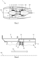
- a motor 1 comprises an inlet sleeve 2 through which the air is admitted to pass through a fan 3 comprising a series of rotating blades 4 followed by a rectifier 6 formed by guide vanes 7 before splitting into a primary flow central FP and a secondary air flow FS surrounding the primary flow.
- the primary flow FP is compressed by low pressure 8 and high pressure 9 compressors before reaching a combustion chamber 11, after which it expands passing through a high pressure turbine 12 and a low pressure turbine 13, before being evacuated by generating auxiliary thrust.
- the secondary flow FS is propelled directly by the fan to generate main thrust.
- Each turbine 12, 13 comprises series of blades oriented radially and regularly spaced around a main axis AX, an external casing 14 surrounding the entire engine.
- the engine 1 integrates a circulation circuit for the lubricating oil and/or the cooling of its components, such as the bearings carrying its elements. rotary or transmission elements that this engine integrates.
- the cooling of this oil is ensured by the secondary flow which is fresh, by means of a heat exchanger.
- This interchange is carried by an internal shroud of the external casing 14 substantially downstream of the guide vanes 7, and it comprises a heat exchange wall 17 having a heat exchange face 18, radially internal, which is bathed by the secondary flow FS to be cooled by it.
- This exchange face 18 is devoid of any relief so as not to disrupt the flow of secondary flow.
- This exchanger 16 comprises internal pipes not shown in which the oil to be cooled circulates, and which are thermally linked to the wall 17 to cool the oil circulating in these pipes.
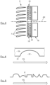
- a disturbing wall 19 is provided located in the extension of the heat exchange face 18 of the exchanger, upstream of the latter with respect to the direction of circulation of the secondary flow FS.
- This disturbing wall 19 locally introduces turbulence into the flow of the secondary flow FS which runs alongside it, to increase the efficiency of the heat exchange between this primary flow and the wall 17.
- the disturbing wall 19 has an external face 21, which is provided with turbulence generators 22, of hollow shapes, making it possible to locally deflect the secondary flow to introduce turbulence.
- the flow then running along the exchange face 18 is in fact turbulent, which significantly increases its thermal exchanges with the face 18, to cool the oil in the exchanger 16 more efficiently and without significantly disturbing the overall flow of the secondary flow.
- FS turbulence generators 22
- the disturbing wall 19 and its face 21, radially internal correspond to the wall and the radially internal face of an annular element 23 integrated into the casing 14.
- This annular element 23 is interposed longitudinally between the blades directions 7 of the rectifier 6 and the exchanger 16, its face 21 being located radially at the same level as the exchange face 18.
- the engine 1 may include several exchangers 16 mounted on the internal circumference of the casing 14, being circumferentially spaced from each other and located longitudinally immediately downstream of the annular element 23.
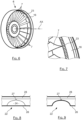
- the turbulence generators 22 can be in the form of substantially hemispherical cavities, as shown schematically on the Figure 4 , opening in the external face 21 advantageously having different dimensions to maximize the turbulence they introduce.
- several turbulence generators 22 are arranged one behind the other in the longitudinal direction.
- the turbulence generators 22 can also have hollow shapes other than the hemispherical shape, as illustrated schematically on the Figure 5 , where several shapes have been represented within the same profile P. It can for example be a pyramidal shape, a shape presenting in section in a plane passing through the axis AX a triangular, rectangular type contour , square or even trapezoidal.
- the turbulence generators 22 have a radial height significantly lower than the height of the vein in the radial direction. This height is the difference in radius between the internal face of the casing 14, which externally delimits the secondary flow, and the external face of a casing internally delimiting the secondary flow.
- the length of these turbulence generators is between one tenth and ten times this height.
- the different turbulence generators 22 have different shapes and different dimensions, so as to increase the turbulence that they generate.
- the disturbing wall 19 has a general shape of a cylindrical crown integrated into the internal face of the casing 14, being located longitudinally between the guide vanes 7 and the heat exchanger(s) 16.
- the turbulence generators 22 are of the variable geometry type so that they can be activated and deactivated as necessary, which then makes it possible to substantially cancel the pressure loss when the required cooling is low or even zero, for example in cold weather.
- the turbulence generator 22 can then be formed from a disturbing wall 19 comprising internal hemispherical cavities 24 opening in the external face 21, with an external face 21 in the form of a flexible and waterproof membrane 26.
- the enclosure delimited by the cavity 24 covered by the membrane 26 is substantially airtight, and the cavity 24 has at its bottom a hole 27 passing through the wall 19 being placed in communication with a pressurization channel 28/ depressurization along the rear face of wall 19.
- the turbulence generator 22 is in the inactive state when its cavity 24 is at ambient pressure, its membrane 26 then having a locally substantially planar shape: it does not define a hollow shape so as not to generate turbulence.
- Activation of the turbulence generator 22 then consists of depressurizing its cavity 24 by depressurizing the channel 28, so that the membrane 26 then follows the shape of this cavity to constitute a hollow portion generating turbulence at the level of the secondary flow FS which the loin.
- Depressurization can be generated by connecting channel 28 to a region located upstream of the fan, where the pressure is lower than downstream of the guide vanes.
- a control system, of the active or passive control type can then be provided to activate or deactivate the turbulence generators 22 depending on whether the cooling requirement is high or low.
- a rod can be provided passing through the hole 27 to have its end secured to the membrane 26.
- This rod can then be controlled electromagnetically to be either pushed in order to align the membrane 26 with the internal face in order to deactivate the generator 22, or to be pulled in order to press this membrane against the bottom of the cavity 24 in order to generate turbulence.
Landscapes
- Engineering & Computer Science (AREA)
- Mechanical Engineering (AREA)
- General Engineering & Computer Science (AREA)
- Chemical & Material Sciences (AREA)
- Combustion & Propulsion (AREA)
- Physics & Mathematics (AREA)
- Thermal Sciences (AREA)
- Heat-Exchange Devices With Radiators And Conduit Assemblies (AREA)
- Structures Of Non-Positive Displacement Pumps (AREA)
Claims (9)
- Wärmetauscher (16) zwischen einem Fluid und einem Luftstrom (FS), der eine Wärmeaustauschwand (17) umfasst, die das Fluid und den Luftstrom (FS) trennt, wobei die Wärmeaustauschwand (17) eine Wärmeaustauschfläche (18) umfasst, die sich parallel zu einer Längsrichtung (AX) der Strömung des Luftstroms (FS) erstreckt und mit der sich der Luftstrom (FS) in Kontakt befindet, wobei dieser Tauscher eine Prallwand (19) umfasst, die sich in Bezug auf die Zirkulationsrichtung des Luftstroms (FS) in der Verlängerung der Wärmeaustauschwand (17) und stromaufwärts derselben erstreckt, wobei die Prallwand (19) mindestens einen Turbulenzgenerator (22) von in Bezug auf die Außenfläche (21) hohler Form umfasst,
wobei der Wärmetauscher (16) dadurch gekennzeichnet ist, dass die Wärmeaustauschfläche (18) kein Relief aufweist. - Tauscher (16) nach dem vorstehenden Anspruch, der mindestens einen Turbulenzgenerator (22) umfasst, der an einem stromaufwärtigen Ende der Prallwand (19) angeordnet ist.
- Tauscher (16) nach Anspruch 1 oder 2, wobei die Prallwand (19) mehrere Turbulenzgeneratoren (22) umfasst, die in mindestens einer Richtung senkrecht zur Längsrichtung (AX) verteilt sind.
- Tauscher (16) nach dem vorstehenden Anspruch, der mindestens zwei aneinandergrenzende Turbulenzgeneratoren (22) umfasst, die unterschiedliche Formen und/oder Abmessungen aufweisen.
- Tauscher (16) nach einem der vorstehenden Ansprüche, wobei mindestens ein Turbulenzgenerator (22) eine Geometrie aufweist, die in Bezug auf die Außenfläche (21) zwischen einem deaktivierten Zustand, in dem er mit der Außenfläche (21) bündig ist, um keine Turbulenzen zu erzeugen, und einem aktivierten Zustand variabel ist, in dem er in Bezug auf die Außenfläche (21) eine Höhlung bildet, um Turbulenzen zu erzeugen.
- Tauscher (16) nach dem vorstehenden Anspruch, wobei die Prallwand (19) innere Hohlräume (24) umfasst, die sich zur Außenfläche (21) hin öffnen und jeweils einem Turbulenzgenerator (22) entsprechen, wobei die Außenfläche (21) eine dichte flexible Membran (26) umfasst, wobei die Aktivierung eines Turbulenzgenerators (22) durch Druckentlastung des entsprechenden inneren Hohlraums (24) erreicht wird.
- Tauscher (16) nach dem vorstehenden Anspruch, in dem ein System zum Steuern des aktivierten oder deaktivierten Zustands der Turbulenzgeneratoren (22) in Bezug auf die Außenfläche (21) integriert ist.
- Tauscher (16) nach einem der Ansprüche 5 bis 7, wobei das Steuersystem pneumatisch ist.
- Turbomaschine (1), die von einem Luftstrom (FS) durchströmt wird, wobei eine Gleichrichterstufe (6) Leitschaufeln (7) umfasst, mit einem Tauscher (16) nach einem der vorstehenden Ansprüche, wobei dieser Tauscher (16) eine Austauschwand (17) umfasst, die in ein Gehäuse (14) der Turbomaschine (1) integriert ist, das einen Strömungskanal des Luftstroms (FS) begrenzt, wobei sich dieser Wärmetauscher (16) stromabwärts des Gleichrichters (6) befindet.
Applications Claiming Priority (2)
| Application Number | Priority Date | Filing Date | Title |
|---|---|---|---|
| FR1914285A FR3104691B1 (fr) | 2019-12-12 | 2019-12-12 | Echangeur de chaleur comportant une paroi perturbatrice à générateurs de turbulence creux |
| PCT/FR2020/052335 WO2021116591A1 (fr) | 2019-12-12 | 2020-12-08 | Echangeur de chaleur comportant une paroi perturbatrice à générateurs de turbulence creux |
Publications (2)
| Publication Number | Publication Date |
|---|---|
| EP4055259A1 EP4055259A1 (de) | 2022-09-14 |
| EP4055259B1 true EP4055259B1 (de) | 2024-04-17 |
Family
ID=69700161
Family Applications (1)
| Application Number | Title | Priority Date | Filing Date |
|---|---|---|---|
| EP20842006.7A Active EP4055259B1 (de) | 2019-12-12 | 2020-12-08 | Wärmetauscher mit einer prallwand mit hohlen turbulenzerzeugern |
Country Status (5)
| Country | Link |
|---|---|
| US (1) | US12196504B2 (de) |
| EP (1) | EP4055259B1 (de) |
| CN (1) | CN114787492B (de) |
| FR (1) | FR3104691B1 (de) |
| WO (1) | WO2021116591A1 (de) |
Families Citing this family (3)
| Publication number | Priority date | Publication date | Assignee | Title |
|---|---|---|---|---|
| FR3104692B1 (fr) * | 2019-12-12 | 2022-12-09 | Safran Aircraft Engines | Echangeur de chaleur comportant une paroi inter-aubes pourvue de générateurs de turbulence creux |
| EP4112451A1 (de) * | 2021-06-28 | 2023-01-04 | BAE SYSTEMS plc | Kanalanordnung und verfahren |
| EP4363311A1 (de) * | 2021-06-28 | 2024-05-08 | BAE SYSTEMS plc | Kanalanordnung und verfahren |
Family Cites Families (15)
| Publication number | Priority date | Publication date | Assignee | Title |
|---|---|---|---|---|
| US20060099073A1 (en) * | 2004-11-05 | 2006-05-11 | Toufik Djeridane | Aspherical dimples for heat transfer surfaces and method |
| US7604461B2 (en) * | 2005-11-17 | 2009-10-20 | General Electric Company | Rotor blade for a wind turbine having aerodynamic feature elements |
| US8061986B2 (en) * | 2010-06-11 | 2011-11-22 | General Electric Company | Wind turbine blades with controllable aerodynamic vortex elements |
| US9376960B2 (en) * | 2010-07-23 | 2016-06-28 | University Of Central Florida Research Foundation, Inc. | Heat transfer augmented fluid flow surfaces |
| US9051943B2 (en) * | 2010-11-04 | 2015-06-09 | Hamilton Sundstrand Corporation | Gas turbine engine heat exchanger fins with periodic gaps |
| US9845147B2 (en) * | 2013-05-01 | 2017-12-19 | Northrop Grumman Systems Corporation | Recessed lift spoiler assembly for airfoils |
| US10208621B2 (en) * | 2015-12-07 | 2019-02-19 | General Electric Company | Surface cooler and an associated method thereof |
| US10697371B2 (en) * | 2015-12-28 | 2020-06-30 | General Electric Company | Method and system for a combined air-oil cooler and fuel-oil cooler heat exchanger |
| US10253785B2 (en) * | 2016-08-31 | 2019-04-09 | Unison Industries, Llc | Engine heat exchanger and method of forming |
| CN106767115B (zh) * | 2016-11-23 | 2019-01-22 | 北京天诚同创电气有限公司 | 换热管及换热器 |
| US20180281048A1 (en) * | 2017-04-04 | 2018-10-04 | Unison Industries, Llc | Methods of forming a heat exchanger |
| US20180328285A1 (en) * | 2017-05-11 | 2018-11-15 | Unison Industries, Llc | Heat exchanger |
| CN110513162B (zh) * | 2018-05-22 | 2022-06-14 | 通用电气公司 | 斗式入口 |
| US11274602B2 (en) * | 2019-05-24 | 2022-03-15 | Pratt & Whitney Canada Corp. | Air cooler for gas turbine engine |
| FR3106621A1 (fr) * | 2020-01-28 | 2021-07-30 | Airbus Operations (S.A.S.) | Turbomachine pour aéronef équipée d’un système thermo-acoustique. |
-
2019
- 2019-12-12 FR FR1914285A patent/FR3104691B1/fr active Active
-
2020
- 2020-12-08 WO PCT/FR2020/052335 patent/WO2021116591A1/fr not_active Ceased
- 2020-12-08 CN CN202080085938.1A patent/CN114787492B/zh active Active
- 2020-12-08 EP EP20842006.7A patent/EP4055259B1/de active Active
- 2020-12-08 US US17/756,986 patent/US12196504B2/en active Active
Also Published As
| Publication number | Publication date |
|---|---|
| CN114787492B (zh) | 2025-06-06 |
| FR3104691A1 (fr) | 2021-06-18 |
| WO2021116591A1 (fr) | 2021-06-17 |
| FR3104691B1 (fr) | 2022-08-12 |
| EP4055259A1 (de) | 2022-09-14 |
| US20220412675A1 (en) | 2022-12-29 |
| CN114787492A (zh) | 2022-07-22 |
| US12196504B2 (en) | 2025-01-14 |
Similar Documents
| Publication | Publication Date | Title |
|---|---|---|
| BE1026919B1 (fr) | Échangeur de chaleur air-huile | |
| EP3735518B1 (de) | Turbinentriebwerk mit wärmetauscher im bypasskanal | |
| EP4055259B1 (de) | Wärmetauscher mit einer prallwand mit hohlen turbulenzerzeugern | |
| BE1027057B1 (fr) | Échangeur de chaleur air-huile | |
| FR3027624A1 (fr) | Circuit de degivrage d'une levre d'entree d'air d'un ensemble propulsif d'aeronef | |
| EP3070317B1 (de) | Kühlung für turbomaschine durch verdampfung | |
| FR2543616A1 (fr) | Controle de l'espace libre dans les joints d'etancheite d'une turbine | |
| CA2726016A1 (fr) | Ensemble d'un disque de turbine d'un moteur a turbine a gaz et d'un tourillon support de palier, circuit de refroidissement d'un disque de turbine d'un tel ensemble | |
| EP3698050B1 (de) | Turboverdichter-aussengehäuse mit integriertem ölbehälter | |
| EP4055261B1 (de) | Wärmetauscher, der eine mit hohlen turbulenzgeneratoren versehene zwischenwand umfasst | |
| EP3519700B1 (de) | Strömungsablenker für ein auslassventilsystem, auslassventilsystem und turbomaschine mit solch einem auslassventilsystem | |
| FR3046200A1 (fr) | Turbomachine comprenant un reservoir d'huile et un echangeur air-huile associe | |
| EP3673154B1 (de) | Abblaskanal einer zwischengehäusenabe für ein flugzeugturbostrahltriebwerk mit kühlkanälen | |
| EP3861195A1 (de) | Turbofantriebwerk mit einem durch seine sekundärströmung gekühlten auslasskegel | |
| FR3039208A1 (fr) | Degivrage d’une levre d’entree d’air et refroidissement d’un carter de turbine d’un ensemble propulsif d’aeronef | |
| EP3824221B1 (de) | Anordnung für eine turbomaschine | |
| EP3535479B1 (de) | Kühlvorrichtung für eine turbine einer turbomaschine | |
| FR3054858A1 (fr) | Turbomachine comportant un dispositif d'entrainement d'un equipement dispose dans le cone d'echappement | |
| FR3057027A1 (fr) | Deflecteur de flux a effet giratoire d'un systeme de vanne de decharge, systeme de vanne de decharge et turbomachine comprenant un tel systeme de vanne de decharge | |
| FR3062169A1 (fr) | Carter de module de turbomachine d'aeronef, comprenant un caloduc associe a un anneau d'etancheite entourant une roue mobile aubagee du module | |
| EP4483039B1 (de) | Turbinentriebwerk für ein flugzeug | |
| FR3081927A1 (fr) | Dispositif de refroidissement d'un carter de turbomachine | |
| EP3735524B1 (de) | Turbinentriebwerk mit einem wärmetauscher bestehend aus mindestens einem deck zwischen schaufeln | |
| FR3152038A1 (fr) | Distributeur, notamment pour une turbine d’une turbomachine d’aéronef | |
| FR3023585A1 (fr) | Carter intermediaire pour un turboreacteur |
Legal Events
| Date | Code | Title | Description |
|---|---|---|---|
| STAA | Information on the status of an ep patent application or granted ep patent |
Free format text: STATUS: UNKNOWN |
|
| STAA | Information on the status of an ep patent application or granted ep patent |
Free format text: STATUS: THE INTERNATIONAL PUBLICATION HAS BEEN MADE |
|
| PUAI | Public reference made under article 153(3) epc to a published international application that has entered the european phase |
Free format text: ORIGINAL CODE: 0009012 |
|
| STAA | Information on the status of an ep patent application or granted ep patent |
Free format text: STATUS: REQUEST FOR EXAMINATION WAS MADE |
|
| 17P | Request for examination filed |
Effective date: 20220608 |
|
| AK | Designated contracting states |
Kind code of ref document: A1 Designated state(s): AL AT BE BG CH CY CZ DE DK EE ES FI FR GB GR HR HU IE IS IT LI LT LU LV MC MK MT NL NO PL PT RO RS SE SI SK SM TR |
|
| DAV | Request for validation of the european patent (deleted) | ||
| DAX | Request for extension of the european patent (deleted) | ||
| GRAP | Despatch of communication of intention to grant a patent |
Free format text: ORIGINAL CODE: EPIDOSNIGR1 |
|
| STAA | Information on the status of an ep patent application or granted ep patent |
Free format text: STATUS: GRANT OF PATENT IS INTENDED |
|
| INTG | Intention to grant announced |
Effective date: 20231215 |
|
| GRAS | Grant fee paid |
Free format text: ORIGINAL CODE: EPIDOSNIGR3 |
|
| GRAA | (expected) grant |
Free format text: ORIGINAL CODE: 0009210 |
|
| STAA | Information on the status of an ep patent application or granted ep patent |
Free format text: STATUS: THE PATENT HAS BEEN GRANTED |
|
| AK | Designated contracting states |
Kind code of ref document: B1 Designated state(s): AL AT BE BG CH CY CZ DE DK EE ES FI FR GB GR HR HU IE IS IT LI LT LU LV MC MK MT NL NO PL PT RO RS SE SI SK SM TR |
|
| REG | Reference to a national code |
Ref country code: GB Ref legal event code: FG4D Free format text: NOT ENGLISH |
|
| REG | Reference to a national code |
Ref country code: CH Ref legal event code: EP |
|
| REG | Reference to a national code |
Ref country code: DE Ref legal event code: R096 Ref document number: 602020029312 Country of ref document: DE |
|
| REG | Reference to a national code |
Ref country code: IE Ref legal event code: FG4D Free format text: LANGUAGE OF EP DOCUMENT: FRENCH |
|
| REG | Reference to a national code |
Ref country code: LT Ref legal event code: MG9D |
|
| REG | Reference to a national code |
Ref country code: NL Ref legal event code: MP Effective date: 20240417 |
|
| REG | Reference to a national code |
Ref country code: AT Ref legal event code: MK05 Ref document number: 1677453 Country of ref document: AT Kind code of ref document: T Effective date: 20240417 |
|
| PG25 | Lapsed in a contracting state [announced via postgrant information from national office to epo] |
Ref country code: NL Free format text: LAPSE BECAUSE OF FAILURE TO SUBMIT A TRANSLATION OF THE DESCRIPTION OR TO PAY THE FEE WITHIN THE PRESCRIBED TIME-LIMIT Effective date: 20240417 |
|
| PG25 | Lapsed in a contracting state [announced via postgrant information from national office to epo] |
Ref country code: NL Free format text: LAPSE BECAUSE OF FAILURE TO SUBMIT A TRANSLATION OF THE DESCRIPTION OR TO PAY THE FEE WITHIN THE PRESCRIBED TIME-LIMIT Effective date: 20240417 |
|
| PG25 | Lapsed in a contracting state [announced via postgrant information from national office to epo] |
Ref country code: IS Free format text: LAPSE BECAUSE OF FAILURE TO SUBMIT A TRANSLATION OF THE DESCRIPTION OR TO PAY THE FEE WITHIN THE PRESCRIBED TIME-LIMIT Effective date: 20240817 |
|
| PG25 | Lapsed in a contracting state [announced via postgrant information from national office to epo] |
Ref country code: BG Free format text: LAPSE BECAUSE OF FAILURE TO SUBMIT A TRANSLATION OF THE DESCRIPTION OR TO PAY THE FEE WITHIN THE PRESCRIBED TIME-LIMIT Effective date: 20240417 |
|
| PG25 | Lapsed in a contracting state [announced via postgrant information from national office to epo] |
Ref country code: HR Free format text: LAPSE BECAUSE OF FAILURE TO SUBMIT A TRANSLATION OF THE DESCRIPTION OR TO PAY THE FEE WITHIN THE PRESCRIBED TIME-LIMIT Effective date: 20240417 Ref country code: FI Free format text: LAPSE BECAUSE OF FAILURE TO SUBMIT A TRANSLATION OF THE DESCRIPTION OR TO PAY THE FEE WITHIN THE PRESCRIBED TIME-LIMIT Effective date: 20240417 |
|
| PG25 | Lapsed in a contracting state [announced via postgrant information from national office to epo] |
Ref country code: GR Free format text: LAPSE BECAUSE OF FAILURE TO SUBMIT A TRANSLATION OF THE DESCRIPTION OR TO PAY THE FEE WITHIN THE PRESCRIBED TIME-LIMIT Effective date: 20240718 |
|
| PG25 | Lapsed in a contracting state [announced via postgrant information from national office to epo] |
Ref country code: PT Free format text: LAPSE BECAUSE OF FAILURE TO SUBMIT A TRANSLATION OF THE DESCRIPTION OR TO PAY THE FEE WITHIN THE PRESCRIBED TIME-LIMIT Effective date: 20240819 |
|
| PG25 | Lapsed in a contracting state [announced via postgrant information from national office to epo] |
Ref country code: ES Free format text: LAPSE BECAUSE OF FAILURE TO SUBMIT A TRANSLATION OF THE DESCRIPTION OR TO PAY THE FEE WITHIN THE PRESCRIBED TIME-LIMIT Effective date: 20240417 |
|
| PG25 | Lapsed in a contracting state [announced via postgrant information from national office to epo] |
Ref country code: AT Free format text: LAPSE BECAUSE OF FAILURE TO SUBMIT A TRANSLATION OF THE DESCRIPTION OR TO PAY THE FEE WITHIN THE PRESCRIBED TIME-LIMIT Effective date: 20240417 |
|
| PG25 | Lapsed in a contracting state [announced via postgrant information from national office to epo] |
Ref country code: PL Free format text: LAPSE BECAUSE OF FAILURE TO SUBMIT A TRANSLATION OF THE DESCRIPTION OR TO PAY THE FEE WITHIN THE PRESCRIBED TIME-LIMIT Effective date: 20240417 |
|
| PG25 | Lapsed in a contracting state [announced via postgrant information from national office to epo] |
Ref country code: LV Free format text: LAPSE BECAUSE OF FAILURE TO SUBMIT A TRANSLATION OF THE DESCRIPTION OR TO PAY THE FEE WITHIN THE PRESCRIBED TIME-LIMIT Effective date: 20240417 |
|
| PG25 | Lapsed in a contracting state [announced via postgrant information from national office to epo] |
Ref country code: PT Free format text: LAPSE BECAUSE OF FAILURE TO SUBMIT A TRANSLATION OF THE DESCRIPTION OR TO PAY THE FEE WITHIN THE PRESCRIBED TIME-LIMIT Effective date: 20240819 Ref country code: PL Free format text: LAPSE BECAUSE OF FAILURE TO SUBMIT A TRANSLATION OF THE DESCRIPTION OR TO PAY THE FEE WITHIN THE PRESCRIBED TIME-LIMIT Effective date: 20240417 Ref country code: NO Free format text: LAPSE BECAUSE OF FAILURE TO SUBMIT A TRANSLATION OF THE DESCRIPTION OR TO PAY THE FEE WITHIN THE PRESCRIBED TIME-LIMIT Effective date: 20240717 Ref country code: LV Free format text: LAPSE BECAUSE OF FAILURE TO SUBMIT A TRANSLATION OF THE DESCRIPTION OR TO PAY THE FEE WITHIN THE PRESCRIBED TIME-LIMIT Effective date: 20240417 Ref country code: IS Free format text: LAPSE BECAUSE OF FAILURE TO SUBMIT A TRANSLATION OF THE DESCRIPTION OR TO PAY THE FEE WITHIN THE PRESCRIBED TIME-LIMIT Effective date: 20240817 Ref country code: HR Free format text: LAPSE BECAUSE OF FAILURE TO SUBMIT A TRANSLATION OF THE DESCRIPTION OR TO PAY THE FEE WITHIN THE PRESCRIBED TIME-LIMIT Effective date: 20240417 Ref country code: GR Free format text: LAPSE BECAUSE OF FAILURE TO SUBMIT A TRANSLATION OF THE DESCRIPTION OR TO PAY THE FEE WITHIN THE PRESCRIBED TIME-LIMIT Effective date: 20240718 Ref country code: FI Free format text: LAPSE BECAUSE OF FAILURE TO SUBMIT A TRANSLATION OF THE DESCRIPTION OR TO PAY THE FEE WITHIN THE PRESCRIBED TIME-LIMIT Effective date: 20240417 Ref country code: ES Free format text: LAPSE BECAUSE OF FAILURE TO SUBMIT A TRANSLATION OF THE DESCRIPTION OR TO PAY THE FEE WITHIN THE PRESCRIBED TIME-LIMIT Effective date: 20240417 Ref country code: BG Free format text: LAPSE BECAUSE OF FAILURE TO SUBMIT A TRANSLATION OF THE DESCRIPTION OR TO PAY THE FEE WITHIN THE PRESCRIBED TIME-LIMIT Effective date: 20240417 Ref country code: AT Free format text: LAPSE BECAUSE OF FAILURE TO SUBMIT A TRANSLATION OF THE DESCRIPTION OR TO PAY THE FEE WITHIN THE PRESCRIBED TIME-LIMIT Effective date: 20240417 Ref country code: RS Free format text: LAPSE BECAUSE OF FAILURE TO SUBMIT A TRANSLATION OF THE DESCRIPTION OR TO PAY THE FEE WITHIN THE PRESCRIBED TIME-LIMIT Effective date: 20240717 |
|
| PGFP | Annual fee paid to national office [announced via postgrant information from national office to epo] |
Ref country code: DE Payment date: 20241121 Year of fee payment: 5 |
|
| PG25 | Lapsed in a contracting state [announced via postgrant information from national office to epo] |
Ref country code: DK Free format text: LAPSE BECAUSE OF FAILURE TO SUBMIT A TRANSLATION OF THE DESCRIPTION OR TO PAY THE FEE WITHIN THE PRESCRIBED TIME-LIMIT Effective date: 20240417 |
|
| REG | Reference to a national code |
Ref country code: DE Ref legal event code: R097 Ref document number: 602020029312 Country of ref document: DE |
|
| PG25 | Lapsed in a contracting state [announced via postgrant information from national office to epo] |
Ref country code: EE Free format text: LAPSE BECAUSE OF FAILURE TO SUBMIT A TRANSLATION OF THE DESCRIPTION OR TO PAY THE FEE WITHIN THE PRESCRIBED TIME-LIMIT Effective date: 20240417 |
|
| PG25 | Lapsed in a contracting state [announced via postgrant information from national office to epo] |
Ref country code: CZ Free format text: LAPSE BECAUSE OF FAILURE TO SUBMIT A TRANSLATION OF THE DESCRIPTION OR TO PAY THE FEE WITHIN THE PRESCRIBED TIME-LIMIT Effective date: 20240417 |
|
| PG25 | Lapsed in a contracting state [announced via postgrant information from national office to epo] |
Ref country code: SK Free format text: LAPSE BECAUSE OF FAILURE TO SUBMIT A TRANSLATION OF THE DESCRIPTION OR TO PAY THE FEE WITHIN THE PRESCRIBED TIME-LIMIT Effective date: 20240417 Ref country code: RO Free format text: LAPSE BECAUSE OF FAILURE TO SUBMIT A TRANSLATION OF THE DESCRIPTION OR TO PAY THE FEE WITHIN THE PRESCRIBED TIME-LIMIT Effective date: 20240417 |
|
| PG25 | Lapsed in a contracting state [announced via postgrant information from national office to epo] |
Ref country code: SM Free format text: LAPSE BECAUSE OF FAILURE TO SUBMIT A TRANSLATION OF THE DESCRIPTION OR TO PAY THE FEE WITHIN THE PRESCRIBED TIME-LIMIT Effective date: 20240417 |
|
| PG25 | Lapsed in a contracting state [announced via postgrant information from national office to epo] |
Ref country code: SM Free format text: LAPSE BECAUSE OF FAILURE TO SUBMIT A TRANSLATION OF THE DESCRIPTION OR TO PAY THE FEE WITHIN THE PRESCRIBED TIME-LIMIT Effective date: 20240417 Ref country code: SK Free format text: LAPSE BECAUSE OF FAILURE TO SUBMIT A TRANSLATION OF THE DESCRIPTION OR TO PAY THE FEE WITHIN THE PRESCRIBED TIME-LIMIT Effective date: 20240417 Ref country code: RO Free format text: LAPSE BECAUSE OF FAILURE TO SUBMIT A TRANSLATION OF THE DESCRIPTION OR TO PAY THE FEE WITHIN THE PRESCRIBED TIME-LIMIT Effective date: 20240417 Ref country code: EE Free format text: LAPSE BECAUSE OF FAILURE TO SUBMIT A TRANSLATION OF THE DESCRIPTION OR TO PAY THE FEE WITHIN THE PRESCRIBED TIME-LIMIT Effective date: 20240417 Ref country code: DK Free format text: LAPSE BECAUSE OF FAILURE TO SUBMIT A TRANSLATION OF THE DESCRIPTION OR TO PAY THE FEE WITHIN THE PRESCRIBED TIME-LIMIT Effective date: 20240417 Ref country code: CZ Free format text: LAPSE BECAUSE OF FAILURE TO SUBMIT A TRANSLATION OF THE DESCRIPTION OR TO PAY THE FEE WITHIN THE PRESCRIBED TIME-LIMIT Effective date: 20240417 |
|
| PG25 | Lapsed in a contracting state [announced via postgrant information from national office to epo] |
Ref country code: IT Free format text: LAPSE BECAUSE OF FAILURE TO SUBMIT A TRANSLATION OF THE DESCRIPTION OR TO PAY THE FEE WITHIN THE PRESCRIBED TIME-LIMIT Effective date: 20240417 |
|
| PLBE | No opposition filed within time limit |
Free format text: ORIGINAL CODE: 0009261 |
|
| STAA | Information on the status of an ep patent application or granted ep patent |
Free format text: STATUS: NO OPPOSITION FILED WITHIN TIME LIMIT |
|
| 26N | No opposition filed |
Effective date: 20250120 |
|
| PG25 | Lapsed in a contracting state [announced via postgrant information from national office to epo] |
Ref country code: SI Free format text: LAPSE BECAUSE OF FAILURE TO SUBMIT A TRANSLATION OF THE DESCRIPTION OR TO PAY THE FEE WITHIN THE PRESCRIBED TIME-LIMIT Effective date: 20240417 |
|
| PG25 | Lapsed in a contracting state [announced via postgrant information from national office to epo] |
Ref country code: MC Free format text: LAPSE BECAUSE OF FAILURE TO SUBMIT A TRANSLATION OF THE DESCRIPTION OR TO PAY THE FEE WITHIN THE PRESCRIBED TIME-LIMIT Effective date: 20240417 |
|
| REG | Reference to a national code |
Ref country code: CH Ref legal event code: PL |
|
| PG25 | Lapsed in a contracting state [announced via postgrant information from national office to epo] |
Ref country code: LU Free format text: LAPSE BECAUSE OF NON-PAYMENT OF DUE FEES Effective date: 20241208 |
|
| PG25 | Lapsed in a contracting state [announced via postgrant information from national office to epo] |
Ref country code: SE Free format text: LAPSE BECAUSE OF FAILURE TO SUBMIT A TRANSLATION OF THE DESCRIPTION OR TO PAY THE FEE WITHIN THE PRESCRIBED TIME-LIMIT Effective date: 20240417 |
|
| REG | Reference to a national code |
Ref country code: BE Ref legal event code: MM Effective date: 20241231 |
|
| PG25 | Lapsed in a contracting state [announced via postgrant information from national office to epo] |
Ref country code: BE Free format text: LAPSE BECAUSE OF NON-PAYMENT OF DUE FEES Effective date: 20241231 |
|
| PG25 | Lapsed in a contracting state [announced via postgrant information from national office to epo] |
Ref country code: CH Free format text: LAPSE BECAUSE OF NON-PAYMENT OF DUE FEES Effective date: 20241231 |
|
| PG25 | Lapsed in a contracting state [announced via postgrant information from national office to epo] |
Ref country code: IE Free format text: LAPSE BECAUSE OF NON-PAYMENT OF DUE FEES Effective date: 20241208 |
|
| PGFP | Annual fee paid to national office [announced via postgrant information from national office to epo] |
Ref country code: GB Payment date: 20251229 Year of fee payment: 6 |
|
| PGFP | Annual fee paid to national office [announced via postgrant information from national office to epo] |
Ref country code: FR Payment date: 20251222 Year of fee payment: 6 |