EP4054962B1 - Method and system for a robotic tape applicator - Google Patents
Method and system for a robotic tape applicator Download PDFInfo
- Publication number
- EP4054962B1 EP4054962B1 EP20885651.8A EP20885651A EP4054962B1 EP 4054962 B1 EP4054962 B1 EP 4054962B1 EP 20885651 A EP20885651 A EP 20885651A EP 4054962 B1 EP4054962 B1 EP 4054962B1
- Authority
- EP
- European Patent Office
- Prior art keywords
- tape
- applicator
- robotized
- sensor
- substrate
- Prior art date
- Legal status (The legal status is an assumption and is not a legal conclusion. Google has not performed a legal analysis and makes no representation as to the accuracy of the status listed.)
- Active
Links
Images




Classifications
-
- B—PERFORMING OPERATIONS; TRANSPORTING
- B65—CONVEYING; PACKING; STORING; HANDLING THIN OR FILAMENTARY MATERIAL
- B65H—HANDLING THIN OR FILAMENTARY MATERIAL, e.g. SHEETS, WEBS, CABLES
- B65H51/00—Forwarding filamentary material
- B65H51/20—Devices for temporarily storing filamentary material during forwarding, e.g. for buffer storage
- B65H51/22—Reels or cages, e.g. cylindrical, with storing and forwarding surfaces provided by rollers or bars
-
- B—PERFORMING OPERATIONS; TRANSPORTING
- B25—HAND TOOLS; PORTABLE POWER-DRIVEN TOOLS; MANIPULATORS
- B25J—MANIPULATORS; CHAMBERS PROVIDED WITH MANIPULATION DEVICES
- B25J11/00—Manipulators not otherwise provided for
-
- B—PERFORMING OPERATIONS; TRANSPORTING
- B25—HAND TOOLS; PORTABLE POWER-DRIVEN TOOLS; MANIPULATORS
- B25J—MANIPULATORS; CHAMBERS PROVIDED WITH MANIPULATION DEVICES
- B25J13/00—Controls for manipulators
- B25J13/08—Controls for manipulators by means of sensing devices, e.g. viewing or touching devices
-
- B—PERFORMING OPERATIONS; TRANSPORTING
- B25—HAND TOOLS; PORTABLE POWER-DRIVEN TOOLS; MANIPULATORS
- B25J—MANIPULATORS; CHAMBERS PROVIDED WITH MANIPULATION DEVICES
- B25J15/00—Gripping heads and other end effectors
- B25J15/0019—End effectors other than grippers
-
- B—PERFORMING OPERATIONS; TRANSPORTING
- B25—HAND TOOLS; PORTABLE POWER-DRIVEN TOOLS; MANIPULATORS
- B25J—MANIPULATORS; CHAMBERS PROVIDED WITH MANIPULATION DEVICES
- B25J9/00—Program-controlled manipulators
- B25J9/16—Program controls
- B25J9/1679—Program controls characterised by the tasks executed
- B25J9/1684—Tracking a line or surface by means of sensors
-
- B—PERFORMING OPERATIONS; TRANSPORTING
- B29—WORKING OF PLASTICS; WORKING OF SUBSTANCES IN A PLASTIC STATE IN GENERAL
- B29C—SHAPING OR JOINING OF PLASTICS; SHAPING OF MATERIAL IN A PLASTIC STATE, NOT OTHERWISE PROVIDED FOR; AFTER-TREATMENT OF THE SHAPED PRODUCTS, e.g. REPAIRING
- B29C70/00—Shaping composites, i.e. plastics material comprising reinforcements, fillers or preformed parts, e.g. inserts
- B29C70/04—Shaping composites, i.e. plastics material comprising reinforcements, fillers or preformed parts, e.g. inserts comprising reinforcements only, e.g. self-reinforcing plastics
- B29C70/28—Shaping operations therefor
- B29C70/30—Shaping by lay-up, i.e. applying fibres, tape or broadsheet on a mould, former or core; Shaping by spray-up, i.e. spraying of fibres on a mould, former or core
- B29C70/38—Automated lay-up, e.g. using robots, laying filaments according to predetermined patterns
- B29C70/386—Automated tape laying [ATL]
-
- B—PERFORMING OPERATIONS; TRANSPORTING
- B65—CONVEYING; PACKING; STORING; HANDLING THIN OR FILAMENTARY MATERIAL
- B65H—HANDLING THIN OR FILAMENTARY MATERIAL, e.g. SHEETS, WEBS, CABLES
- B65H16/00—Unwinding, paying-out webs
- B65H16/10—Arrangements for effecting positive rotation of web roll
- B65H16/103—Arrangements for effecting positive rotation of web roll in which power is applied to web-roll spindle
-
- B—PERFORMING OPERATIONS; TRANSPORTING
- B65—CONVEYING; PACKING; STORING; HANDLING THIN OR FILAMENTARY MATERIAL
- B65H—HANDLING THIN OR FILAMENTARY MATERIAL, e.g. SHEETS, WEBS, CABLES
- B65H19/00—Changing the web roll
- B65H19/10—Changing the web roll in unwinding mechanisms or in connection with unwinding operations
- B65H19/18—Attaching, e.g. pasting, the replacement web to the expiring web
- B65H19/1842—Attaching, e.g. pasting, the replacement web to the expiring web standing splicing, i.e. the expiring web being stationary during splicing contact
- B65H19/1852—Attaching, e.g. pasting, the replacement web to the expiring web standing splicing, i.e. the expiring web being stationary during splicing contact taking place at a distance from the replacement roll
-
- B—PERFORMING OPERATIONS; TRANSPORTING
- B65—CONVEYING; PACKING; STORING; HANDLING THIN OR FILAMENTARY MATERIAL
- B65H—HANDLING THIN OR FILAMENTARY MATERIAL, e.g. SHEETS, WEBS, CABLES
- B65H20/00—Advancing webs
- B65H20/005—Electrical drive motor control devices therefor
-
- B—PERFORMING OPERATIONS; TRANSPORTING
- B65—CONVEYING; PACKING; STORING; HANDLING THIN OR FILAMENTARY MATERIAL
- B65H—HANDLING THIN OR FILAMENTARY MATERIAL, e.g. SHEETS, WEBS, CABLES
- B65H20/00—Advancing webs
- B65H20/30—Arrangements for accumulating surplus web
- B65H20/32—Arrangements for accumulating surplus web by making loops
- B65H20/34—Arrangements for accumulating surplus web by making loops with rollers
-
- B—PERFORMING OPERATIONS; TRANSPORTING
- B65—CONVEYING; PACKING; STORING; HANDLING THIN OR FILAMENTARY MATERIAL
- B65H—HANDLING THIN OR FILAMENTARY MATERIAL, e.g. SHEETS, WEBS, CABLES
- B65H23/00—Registering, tensioning, smoothing or guiding webs
- B65H23/04—Registering, tensioning, smoothing or guiding webs longitudinally
- B65H23/044—Sensing web tension
-
- B—PERFORMING OPERATIONS; TRANSPORTING
- B65—CONVEYING; PACKING; STORING; HANDLING THIN OR FILAMENTARY MATERIAL
- B65H—HANDLING THIN OR FILAMENTARY MATERIAL, e.g. SHEETS, WEBS, CABLES
- B65H35/00—Delivering articles from cutting or line-perforating machines; Article or web delivery apparatus incorporating cutting or line-perforating devices, e.g. adhesive tape dispensers
- B65H35/0006—Article or web delivery apparatus incorporating cutting or line-perforating devices
- B65H35/002—Hand-held or table apparatus
- B65H35/0026—Hand-held or table apparatus for delivering pressure-sensitive adhesive tape
- B65H35/0033—Hand-held or table apparatus for delivering pressure-sensitive adhesive tape and affixing it to a surface
-
- B—PERFORMING OPERATIONS; TRANSPORTING
- B65—CONVEYING; PACKING; STORING; HANDLING THIN OR FILAMENTARY MATERIAL
- B65H—HANDLING THIN OR FILAMENTARY MATERIAL, e.g. SHEETS, WEBS, CABLES
- B65H35/00—Delivering articles from cutting or line-perforating machines; Article or web delivery apparatus incorporating cutting or line-perforating devices, e.g. adhesive tape dispensers
- B65H35/0006—Article or web delivery apparatus incorporating cutting or line-perforating devices
- B65H35/0073—Details
- B65H35/008—Arrangements or adaptations of cutting devices
-
- B—PERFORMING OPERATIONS; TRANSPORTING
- B65—CONVEYING; PACKING; STORING; HANDLING THIN OR FILAMENTARY MATERIAL
- B65H—HANDLING THIN OR FILAMENTARY MATERIAL, e.g. SHEETS, WEBS, CABLES
- B65H51/00—Forwarding filamentary material
- B65H51/20—Devices for temporarily storing filamentary material during forwarding, e.g. for buffer storage
-
- B—PERFORMING OPERATIONS; TRANSPORTING
- B65—CONVEYING; PACKING; STORING; HANDLING THIN OR FILAMENTARY MATERIAL
- B65H—HANDLING THIN OR FILAMENTARY MATERIAL, e.g. SHEETS, WEBS, CABLES
- B65H51/00—Forwarding filamentary material
- B65H51/30—Devices controlling the forwarding speed to synchronise with supply, treatment, or take-up apparatus
-
- B—PERFORMING OPERATIONS; TRANSPORTING
- B65—CONVEYING; PACKING; STORING; HANDLING THIN OR FILAMENTARY MATERIAL
- B65H—HANDLING THIN OR FILAMENTARY MATERIAL, e.g. SHEETS, WEBS, CABLES
- B65H59/00—Adjusting or controlling tension in filamentary material, e.g. for preventing snarling; Applications of tension indicators
- B65H59/02—Adjusting or controlling tension in filamentary material, e.g. for preventing snarling; Applications of tension indicators by regulating delivery of material from supply package
- B65H59/04—Adjusting or controlling tension in filamentary material, e.g. for preventing snarling; Applications of tension indicators by regulating delivery of material from supply package by devices acting on package or support
-
- B—PERFORMING OPERATIONS; TRANSPORTING
- B65—CONVEYING; PACKING; STORING; HANDLING THIN OR FILAMENTARY MATERIAL
- B65H—HANDLING THIN OR FILAMENTARY MATERIAL, e.g. SHEETS, WEBS, CABLES
- B65H59/00—Adjusting or controlling tension in filamentary material, e.g. for preventing snarling; Applications of tension indicators
- B65H59/10—Adjusting or controlling tension in filamentary material, e.g. for preventing snarling; Applications of tension indicators by devices acting on running material and not associated with supply or take-up devices
- B65H59/36—Floating elements compensating for irregularities in supply or take-up of material
-
- B—PERFORMING OPERATIONS; TRANSPORTING
- B65—CONVEYING; PACKING; STORING; HANDLING THIN OR FILAMENTARY MATERIAL
- B65H—HANDLING THIN OR FILAMENTARY MATERIAL, e.g. SHEETS, WEBS, CABLES
- B65H59/00—Adjusting or controlling tension in filamentary material, e.g. for preventing snarling; Applications of tension indicators
- B65H59/38—Adjusting or controlling tension in filamentary material, e.g. for preventing snarling; Applications of tension indicators by regulating speed of driving mechanism of unwinding, paying-out, forwarding, winding, or depositing devices, e.g. automatically in response to variations in tension
- B65H59/384—Adjusting or controlling tension in filamentary material, e.g. for preventing snarling; Applications of tension indicators by regulating speed of driving mechanism of unwinding, paying-out, forwarding, winding, or depositing devices, e.g. automatically in response to variations in tension using electronic means
- B65H59/387—Regulating unwinding speed
-
- B—PERFORMING OPERATIONS; TRANSPORTING
- B65—CONVEYING; PACKING; STORING; HANDLING THIN OR FILAMENTARY MATERIAL
- B65H—HANDLING THIN OR FILAMENTARY MATERIAL, e.g. SHEETS, WEBS, CABLES
- B65H67/00—Replacing or removing cores, receptacles, or completed packages at paying-out, winding, or depositing stations
- B65H67/02—Arrangements for removing spent cores or receptacles and replacing by supply packages at paying-out stations
-
- B—PERFORMING OPERATIONS; TRANSPORTING
- B65—CONVEYING; PACKING; STORING; HANDLING THIN OR FILAMENTARY MATERIAL
- B65H—HANDLING THIN OR FILAMENTARY MATERIAL, e.g. SHEETS, WEBS, CABLES
- B65H69/00—Methods of, or devices for, interconnecting successive lengths of material; Knot-tying devices ;Control of the correct working of the interconnecting device
- B65H69/06—Methods of, or devices for, interconnecting successive lengths of material; Knot-tying devices ;Control of the correct working of the interconnecting device by splicing
-
- B—PERFORMING OPERATIONS; TRANSPORTING
- B25—HAND TOOLS; PORTABLE POWER-DRIVEN TOOLS; MANIPULATORS
- B25J—MANIPULATORS; CHAMBERS PROVIDED WITH MANIPULATION DEVICES
- B25J19/00—Accessories fitted to manipulators, e.g. for monitoring, for viewing; Safety devices combined with or specially adapted for use in connection with manipulators
- B25J19/06—Safety devices
-
- B—PERFORMING OPERATIONS; TRANSPORTING
- B65—CONVEYING; PACKING; STORING; HANDLING THIN OR FILAMENTARY MATERIAL
- B65H—HANDLING THIN OR FILAMENTARY MATERIAL, e.g. SHEETS, WEBS, CABLES
- B65H2301/00—Handling processes for sheets or webs
- B65H2301/50—Auxiliary process performed during handling process
- B65H2301/51—Modifying a characteristic of handled material
- B65H2301/511—Processing surface of handled material upon transport or guiding thereof, e.g. cleaning
-
- B—PERFORMING OPERATIONS; TRANSPORTING
- B65—CONVEYING; PACKING; STORING; HANDLING THIN OR FILAMENTARY MATERIAL
- B65H—HANDLING THIN OR FILAMENTARY MATERIAL, e.g. SHEETS, WEBS, CABLES
- B65H2301/00—Handling processes for sheets or webs
- B65H2301/50—Auxiliary process performed during handling process
- B65H2301/51—Modifying a characteristic of handled material
- B65H2301/511—Processing surface of handled material upon transport or guiding thereof, e.g. cleaning
- B65H2301/5112—Processing surface of handled material upon transport or guiding thereof, e.g. cleaning removing material from outer surface
- B65H2301/51122—Processing surface of handled material upon transport or guiding thereof, e.g. cleaning removing material from outer surface peeling layer of material
-
- B—PERFORMING OPERATIONS; TRANSPORTING
- B65—CONVEYING; PACKING; STORING; HANDLING THIN OR FILAMENTARY MATERIAL
- B65H—HANDLING THIN OR FILAMENTARY MATERIAL, e.g. SHEETS, WEBS, CABLES
- B65H2301/00—Handling processes for sheets or webs
- B65H2301/50—Auxiliary process performed during handling process
- B65H2301/51—Modifying a characteristic of handled material
- B65H2301/515—Cutting handled material
- B65H2301/5151—Cutting handled material transversally to feeding direction
-
- B—PERFORMING OPERATIONS; TRANSPORTING
- B65—CONVEYING; PACKING; STORING; HANDLING THIN OR FILAMENTARY MATERIAL
- B65H—HANDLING THIN OR FILAMENTARY MATERIAL, e.g. SHEETS, WEBS, CABLES
- B65H2404/00—Parts for transporting or guiding the handled material
- B65H2404/50—Surface of the elements in contact with the forwarded or guided material
- B65H2404/53—Surface of the elements in contact with the forwarded or guided material with particular mechanical, physical properties
- B65H2404/531—Surface of the elements in contact with the forwarded or guided material with particular mechanical, physical properties particular coefficient of friction
- B65H2404/5311—Surface with different coefficients of friction
-
- B—PERFORMING OPERATIONS; TRANSPORTING
- B65—CONVEYING; PACKING; STORING; HANDLING THIN OR FILAMENTARY MATERIAL
- B65H—HANDLING THIN OR FILAMENTARY MATERIAL, e.g. SHEETS, WEBS, CABLES
- B65H2404/00—Parts for transporting or guiding the handled material
- B65H2404/50—Surface of the elements in contact with the forwarded or guided material
- B65H2404/53—Surface of the elements in contact with the forwarded or guided material with particular mechanical, physical properties
- B65H2404/539—Surface of the elements in contact with the forwarded or guided material with particular mechanical, physical properties other
- B65H2404/5391—Surface of the elements in contact with the forwarded or guided material with particular mechanical, physical properties other adhesive properties
-
- B—PERFORMING OPERATIONS; TRANSPORTING
- B65—CONVEYING; PACKING; STORING; HANDLING THIN OR FILAMENTARY MATERIAL
- B65H—HANDLING THIN OR FILAMENTARY MATERIAL, e.g. SHEETS, WEBS, CABLES
- B65H2406/00—Means using fluid
- B65H2406/30—Suction means
- B65H2406/31—Suction box; Suction chambers
- B65H2406/312—Suction box; Suction chambers incorporating means for transporting the handled material against suction force
-
- B—PERFORMING OPERATIONS; TRANSPORTING
- B65—CONVEYING; PACKING; STORING; HANDLING THIN OR FILAMENTARY MATERIAL
- B65H—HANDLING THIN OR FILAMENTARY MATERIAL, e.g. SHEETS, WEBS, CABLES
- B65H2553/00—Sensing or detecting means
- B65H2553/80—Arangement of the sensing means
-
- B—PERFORMING OPERATIONS; TRANSPORTING
- B65—CONVEYING; PACKING; STORING; HANDLING THIN OR FILAMENTARY MATERIAL
- B65H—HANDLING THIN OR FILAMENTARY MATERIAL, e.g. SHEETS, WEBS, CABLES
- B65H2555/00—Actuating means
- B65H2555/20—Actuating means angular
- B65H2555/24—Servomotors
-
- B—PERFORMING OPERATIONS; TRANSPORTING
- B65—CONVEYING; PACKING; STORING; HANDLING THIN OR FILAMENTARY MATERIAL
- B65H—HANDLING THIN OR FILAMENTARY MATERIAL, e.g. SHEETS, WEBS, CABLES
- B65H2555/00—Actuating means
- B65H2555/30—Multi-axis
-
- B—PERFORMING OPERATIONS; TRANSPORTING
- B65—CONVEYING; PACKING; STORING; HANDLING THIN OR FILAMENTARY MATERIAL
- B65H—HANDLING THIN OR FILAMENTARY MATERIAL, e.g. SHEETS, WEBS, CABLES
- B65H2557/00—Means for control not provided for in groups B65H2551/00 - B65H2555/00
- B65H2557/50—Use of particular electromagnetic waves, e.g. light, radiowaves or microwaves
- B65H2557/51—Laser
-
- B—PERFORMING OPERATIONS; TRANSPORTING
- B65—CONVEYING; PACKING; STORING; HANDLING THIN OR FILAMENTARY MATERIAL
- B65H—HANDLING THIN OR FILAMENTARY MATERIAL, e.g. SHEETS, WEBS, CABLES
- B65H2701/00—Handled material; Storage means
- B65H2701/10—Handled articles or webs
- B65H2701/11—Dimensional aspect of article or web
- B65H2701/113—Size
- B65H2701/1133—Size of webs
- B65H2701/11332—Size of webs strip, tape, narrow web
-
- B—PERFORMING OPERATIONS; TRANSPORTING
- B65—CONVEYING; PACKING; STORING; HANDLING THIN OR FILAMENTARY MATERIAL
- B65H—HANDLING THIN OR FILAMENTARY MATERIAL, e.g. SHEETS, WEBS, CABLES
- B65H2701/00—Handled material; Storage means
- B65H2701/30—Handled filamentary material
- B65H2701/37—Tapes
- B65H2701/377—Adhesive tape
-
- B—PERFORMING OPERATIONS; TRANSPORTING
- B65—CONVEYING; PACKING; STORING; HANDLING THIN OR FILAMENTARY MATERIAL
- B65H—HANDLING THIN OR FILAMENTARY MATERIAL, e.g. SHEETS, WEBS, CABLES
- B65H2701/00—Handled material; Storage means
- B65H2701/30—Handled filamentary material
- B65H2701/37—Tapes
- B65H2701/377—Adhesive tape
- B65H2701/3772—Double-sided
-
- B—PERFORMING OPERATIONS; TRANSPORTING
- B65—CONVEYING; PACKING; STORING; HANDLING THIN OR FILAMENTARY MATERIAL
- B65H—HANDLING THIN OR FILAMENTARY MATERIAL, e.g. SHEETS, WEBS, CABLES
- B65H37/00—Article or web delivery apparatus incorporating devices for performing specified auxiliary operations
- B65H37/002—Web delivery apparatus, the web serving as support for articles, material or another web
Definitions
- the present disclosure relates to an automated apparatus for application of adhesive tape on a substrate.
- Such an apparatus is known from e.g. US 9 175 190 B2 .
- Adhesive-backed tape is commonly applied to body surfaces, interior and exterior claddings and panels (e.g. trim, moldings, covers, trays, panels, doors and hatches) of a vehicle (e.g., an automobile, aircraft, or watercraft), or structures (e.g. buildings, HVAC units).
- a vehicle e.g., an automobile, aircraft, or watercraft
- structures e.g. buildings, HVAC units.
- an adhesive-backed tape mounted around the periphery of a cladding on a vehicle component provides a seal which helps to control water intrusion, and reduce cabin noise due to wind when the vehicle is in motion, as well as control dust intrusion into the cabin and engine parts.
- Such tapes may be manually installed, however such a process is not only slow, but labour intensive, and prone to human error.
- the application process may not be uniform, predictable or reproducible.
- the robotized tape application system allows for faster application rates, and increased efficiency; accurate and consistent application of the tape; reduced labor costs and increased flexibility by allowing for longer application times, and application of tape in more complex paths on the substrate.
- the robotized tape application minimizes human intervention and human error during runtime.
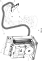
- FIG. 1a-e there is shown a robotic tape applicator system for attaching a tape to a receiving surface or a substrate, generally identified by numeral 10, in an exemplary embodiment.
- Figures 1b and 1c show tape 11, such as adhesive tape, or double-sided tape, comprising material 12 and tape liner 13, while Figures 1d and 1e show a roll and spool of adhesive lined tape 11, respectively.
- System 10 comprises payout device 14 which feeds adhesive tape 11 into flexible conduit 15 terminating at adhesive tape applicator head 18 mounted on robotic arm 19 of an industrial robot 20 with various axis configurations.
- the industrial robot may include six axes, or six degrees of freedom, which allow for greater flexibility.
- flexible conduit 15 bends as needed based on the movements of robotic arm 19.
- Flexible conduit 15 comprises infeed conduit 16 through which adhesive tape 11 is conveyed from payout device 14 to applicator head 18, and alongside flexible infeed conduit 16 is flexible outfeed conduit 21 which transports liner 13 which is removed from material 12 and dispensed during the application process.
- payout device 14 comprises payout spool shaft 30 rotatably attached to the mounting frame 32, and payout spool shaft or spindle 30 receives payout spool 34 of adhesive tape 11.
- elastomeric adhesive lined tape 11 include, but are not limited to, crushed ethylene propylene diene monomers (EPDM); neoprene closed cell; expanded polyvinyl chloride (PVC); polyethylene; acrylic foam tapes (e.g. very high bond (VHB) tape); weld-thru tapes, sealer tapes, electrical circuit tapes, heat activated tapes.
- Tape 11 may include a range of widths, thickness and length depending on the application.
- tape 11 comprises a width ranging from 1.5mm to 25mm or material thickness ranges from 0.05mm to 20mm.
- adhesive tape 11 can be fed from any type of tape dispensing means or tape supply means, such as a conveying platform.
- Payout device 14 also comprises system controller 40 which exchanges signals with associated components, such as, sensors, motors, actuators, and communicates with robotic arm 19, and applicator head 18 and other components, to provide tape 11 on demand as called for by applicator head 18 in a relatively fast, accurate and consistent manner.
- Human machine interface 42 is communicatively coupled to system controller 40 for inputting program instructions and configure system 10 settings, and outputting alerts, warnings, notifications and displaying system 10 settings.
- System controller 40 comprises board logic or programmable circuitry or a processor.
- payout spool 34 of tape 11 is unwound by toggling spool brake 44 on and off, and tape 11 is fed through a series of lower pulleys 46 and upper pulleys 48 of tape material accumulator 50.
- a spool motor is controllable to initiate and stop rotation of payout spool shaft 30 or regulate the rotational speed of payout spool shaft 30.
- Pulleys 46, 48 accumulate tape 11 for on the fly spool changes, and account for any feeding variances, as will be explained later.
- Lower pulleys 46 are mounted on lower pulley arm 52, and upper pulleys are mounted on upper pulley arm 54.
- Lower pulley arm 52 slides vertically, such that the position of lower pulley arm 52 determines the length of tape 11 stored in accumulator 50. As tape 11 is dispensed, lower pulley arm 52 rises, and the amount of stored tape 11 decreases. As an example, in the upper most position of lower pulley arm 52 there may be 2 meters of tape 11 in accumulator 50, while in the lower most position of lower pulley arm 52 there could be as much as 20 meters of tape 11 depending on the number of pulleys 46, 48 and windings of tape 11.
- Accumulator position sensor 60 is mounted on frame 32 of accumulator 50 to detect the position of movable lower pulley arm 52, and spool level sensor 68 detects amount of tape 11 on payout spool 34.
- Accumulator position sensor 60 comprises a plurality of set points e.g. lower limit and upper limit. For example, when lower pulley arm 52 passes the upper limit set point spool brake 44 is released to allow new tape 11 to feed into accumulator 50, as lower pulley arm 52 falls under the force of gravity, spool 34 unwinds and accumulator 50 fills with tape 11. When lower pulley arm 52 passes the lower limit set point brake 44 is re-applied to stop spool 34 unwinding.
- tape 11 exits accumulator 50 into payout drive mechanism 70, which indexes tape 11 out towards robotic arm 19 via flexible infeed conduit 16 at a controlled, metered rate as it is called for by applicator head 18.
- Drive mechanism 70 may include servo motors or stepper motors, pulleys, to control the advancement of tape 11 to applicator head 18.
- spool level sensor 68 indicates spool 34 is empty, or close to being completely depleted
- payout device 14 switches into a spool change mode, as will be described later.
- accumulator 50 is associated with at least one accumulator position sensor 60 which determines a numerical position of tape 11 in accumulator 50, ranging from a predefined low threshold to a predefined high threshold.
- accumulator position sensor 60 comprises a plurality of sensors located at different positions associated with the lower limit and the higher limit.
- Payout drive mechanism 70 comprises fluid amplifier 72 which creates a vacuum effect inside therein to effectively reduce frictional forces between tape 11 and the interior wall of flexible conduit 16 as tape 11 is fed along flexible conduit 16 towards applicator head 18. The vacuum is activated only when payout drive mechanism 70 is feeding new tape 11.
- tape 11 exits flexible tube 16 at robotic applicator head 18, and tape 11 is wound around material buffer 80 by buffer refill mechanism 82.
- material buffer 80 is a loop of tape 11, or a reserve, of variable size, which accounts for feeding variances between payout drive mechanism 70 and head drive mechanism 90 and promotes application of consistent tension to tape 11, or controls the tension forces associated with tape 11.
- buffer refill mechanism comprises resilient means and a slide mechanism, such that as material buffer 80 shrinks, sensor 92 detects the level of compressed buffer loop 101 and commands payout drive mechanism 70 to send more tape 11 causing material buffer 80 to grow again.
- Material buffer 80 is associated with buffer sensor 92 which determines a numerical position of material buffer 80, ranging from a predefined low threshold to a predefined high threshold. When material buffer 80 reaches the low threshold payout drive mechanism 70 is called upon to feed additional tape 11 to refill material buffer 80. When the buffer reaches the high threshold payout drive mechanism 70 is shut off.
- the numerical data being measured by position sensor 92 can predict tape 11 jams and tape 11 breakages and shut down system 10, thereby minimizing any possible further damage or equipment faults.
- head drive mechanism 90 is actuated and feeds tape 11 from material buffer 80 towards the application tip 100.
- head drive mechanism 90 may include servo motors or stepper motors to control the advancement of tape 11 to applicator tip 100.
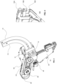
- head drive mechanism 90 comprises a set of rollers or gears coupled to an electric motor, and configured to pull tape 11 around application tip 100, as shown in Figures 3 and 4 .
- Material 12 is peeled off liner 13, or vice versa, by virtue of the geometry of application tip 100, which comprises rounded member 102, exposing the adhesive layer.
- Material 12 is advanced to application tip 100 prior to the commencement of the application of material 12 to the substrate, and buffer 101 includes a loop of tape 11 which accounts for feeding variances between payout drive mechanism 70 and head drive mechanism 90 and to ensure consistent tension is applied to tape 11, and assist with peeling off liner 13, and feeding tape 11. Accordingly, following program instructions executable by system controller 40 robotic arm 19 moves to the start position on the substrate and applicator head 18 begins to apply material 12 along a predefined application path while sending a feed command to actuate head drive mechanism 90 to index more tape 11, as needed.
- the predefined paths may be linear, nonlinear, three-dimensional, and so forth.
- specialized hardware associated with robotic arm 19 determines the speed of robotic arm 19 movements, and transmits that speed to system controller 40, and the speed of head drive mechanism 90 is automatically adjusted to match the speed of the movements of the robotic arm 19. In other instances, the speeds may be calculated and manually adjusted in the program. With the aid of encoders or other tracking means, system controller 40 can determine the amount of tape 11 passing under applicator tip 100, including the precise location where tape 11 is to be applied.
- wet-out roller 104 associated with applicator head 18 follows the path of applied material 12 and applies pressure to material 12 to enhance adherement; or activate the adhesive on pressure-sensitive adhesive tapes 11.
- an additional tool is used to apply adhesion promoter on the substrate, such as along the predefined application path, before material 12 is applied.
- a vision system may be used to detect the presence of adhesion promoter on the substrate, and automatically apply material 12 to the sensed locations on the substrate.
- applicator head 18 reaches the end of its pre-programmed application path it sends a command to system controller 40.
- a cut sequence commences, and entails commanding blade actuator 95 to actuate and cause straight blade 106 to sever tape 11.
- Straight blade 106 performs a precision kiss cut by severing material 12 without severing liner 13 underlying material 12. Accordingly, the speed and depth of straight blade 106 into material 12 is precisely calibrated and stored in the calibration parameters in memory means associated with system controller 40, and may be dependent on the thickness of material 12 and liner 13. Alternatively, the speed and depth of straight blade 106 into material 12 is precisely calibrated via mechanical means. For example, a positioning device comprising one of a threaded adjuster, an eccentric lobe, and a stop capable of modification to suit a predetermined thickness, for performing adjustments. Blade actuator 95 may be any one a fluidic muscle, electric actuator, pneumatic actuator, and a hydraulic actuator.
- robotic arm 19 Upon completion of the cut, robotic arm 19 makes a final move to apply the last millimeters of material 12 up to the cut location and rolls material 12 with wet-out roller 104.
- blade 106 may be serrated or non-serrated, angled, curved, or heated to enhance the cutting sequence.
- outfeed tube 21 includes outfeed fluid amplifier 73 to pull the spent liner 13 away from applicator head 18 towards payout device 14, where used liner 13 is collected in a disposal bin 110.
- Payout device 14 may include cutting device 66 to cut used liner 13 to manageable sizes to facilitate disposal.
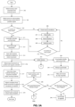
- robotic arm 19 in a cell receives a start command from an external source having programmed instructions to apply adhesive tape 11 along a predefined path on a substrate.
- robotic arm 19 moves to a start position and the external source sends a robot in position signal (204), and system controller 40 determines whether payout device 14 is in auto mode (205)
- system controller 40 activates fluid amplifier 73 (211), otherwise system controller 40 determines the conditions of accumulator 50 and payout spool 34 based on the status signals from the accumulator sensor 60, and spool level sensor 68, step 206.
- step 210 system controller 40 determines whether payout device 14 is in auto mode, and when payout device 14 is not in auto mode the process returns to step 206, otherwise system controller 40 activates payout drive mechanism 70, fluid amplifier 72 to feed tape 11 along flexible infeed conduit 16 towards applicator head 18 (211), including head drive mechanism 90 to feed material 12 to the application tip 100 (212).
- robotic arm 19 commences applying tape 11 along the predefined path on the substrate, and head drive mechanism 90 indexes material 11 in relation to robotic arm 19 movement.
- head drive mechanism 90 indexes material 11 in relation to robotic arm 19 movement.
- system controller 40 continually determines the level of buffer 101 based on the output signals from buffer sensor 92 (222).
- robotic arm 19 stops and signals system controller 40 (216), and system controller 40 issues a command to head drive mechanism 90 to stop indexing material 12 and another command to applicator head 18 to actuate straight blade 106 to sever material 12 (217), and the process continues with robotic arm 19 applying material 12 at a new location of the predefined path, or another predefined path on the substrate.
- robotic arm 19 completes the final path movement to apply the remainder of material 12, and payout device 14 issues a cycle complete signal to the external source (219), and the cycle ends.
- step 215 the length of material 12 in buffer 101 of applicator head 18 diminishes (220), and system controller 40 continually determines the level of buffer 101 based on the output signals from buffer sensor 92 (222). If the level of buffer 101 is within a predefined threshold then the process continues (224), otherwise a request for more material 12 is made (226) and system controller 40 activates fluid amplifier 72 to facilitate transport of material 12 via infeed conduit 16 (228). Payout drive mechanism 70 indexes material 12 to applicator head 18 to replenish buffer loop 101 (230), and system controller 40 determines whether the level of buffer 80 is within the predetermined levels based on the output signals from buffer sensor 92 (232).
- step 224 a determination is made as to whether material 12 feeding has timed out (234), if there is a time out then a fault alarm or notification is issued by system controller 40 alerting an operator to rectify the situation (236), otherwise the process returns to step 232.
- step 215 As material 12 is applied to the substrate the length of material 12 in buffer 80 and accumulator 50 also diminishes (238), spool brake 44 is released (240) and lower pulley arm 52 lowers by way of gravity (242), and system controller 40 determines whether the lower threshold has been flagged based on the output from accumulator sensor 60 when lower limit set point is triggered (244). When the lower threshold has been flagged then spool brake 44 is re-applied (246) and the process returns to step 238; otherwise the process proceeds to step 248 where system controller 40 determines the level of payout spool 34 based on the output from payout spool sensor 68.
- payout spool sensor 68 indicates that payout spool 34 is empty then a fault alarm or notification is issued by system controller 40 to alert an operator to rectify the situation (250), otherwise system controller 40 determines whether accumulator 50 upper threshold has been flagged (252) based on output signals from accumulator sensor 60.
- depleted spool 34 may be swapped for a new spool 34 of tape 11 without interrupting the application cycle in progress. Accordingly, the spool 34 changeover minimizes production downtime. If upper threshold has not been flagged then operation continues (253), otherwise material clamp 36 on incoming side of accumulator 50 is actuated (254) to clamp the new tape 11 entering accumulator 50. In step 255 system controller 40 issues an alert notifying an operator to change spool 34.
- payout device 14 continues to index tape 11 to applicator head 18 by using up reserve tape 11 (e.g. up to 20 meters) stored in accumulator 50, while operator swaps spools 34 within a predefined swap time i.e. the amount of time to complete a spool 34 change (256).
- the predefined swap time may be determined by dividing the length (meters) of the reserve tape 11 in accumulator 50 by application rate of tape 11 (meters per minute). For example, for a tape 11 reserve of 20 meters, and an application rate of 1 meter per minute, then the predefined swap time is 20 minutes.
- the predefined swap time depends on the cycle time of system 10, user preferences and settings.
- step 257 when system controller 40 determines that the spool change and the splice process is completed before lower pulley arm 52 passes upper limit of sensor 60, then the process proceeds to step 266, otherwise operation of payout device 14 is halted by system controller 40 (258) and operator is alerted by system controller 40 to change spool 34 (256).
- Operator cuts tape 11 at splice location (259) and operator removes empty spool 34 and loads a new full spool 34 (260).
- operator creates splice joint to join an end of new tape 11 to an end of in-progress tape 11 clamped before accumulator 50 (262).
- Splicing fixture 65 is provided to make these splices expeditiously, and in a consistent manner.
- the purge cycle consists of applying tape 11 with the splice to disposal surface, that is, not on the predefined application path. Once enough tape 11 has been purged to ensure the splice is eliminated, system 10 resumes normal operation, and the process ends. Alternatively, the operator may load a new spool 260 and thread the new tape 11 in the payout device 14 and advance the tape 11 to the applicator head 18, that is, without any splice joints.
- adhesive tape 11 can be single- or double-sided tape, in a monolithic or layered format.
- material clamp 36 on the incoming side of accumulator 50 is manually actuated to clamp the new tape 11 entering accumulator 50.
- material clamp 36 on the incoming side of accumulator 50 is electrically actuated to clamp the new tape 11 entering accumulator 50.
- material clamp 36 on the incoming side of accumulator 50 is pneumatically actuated to clamp the new tape 11 entering accumulator 50.
- adhesive tape 11 travels through a delamination device comprising rollers configured to separate material 12 and removable liner 13 from each other temporarily before reapplying material 12 to removable liner 13 to loosen the bond.
- applicator head 18 comprises a vision system, which includes an image capture device to verify the correct application of material 12 on the substrate part or work piece, and identify substrate features or edges to facilitate self-alignment of application tip 100 with the predefined application path.
- a vision system which includes an image capture device to verify the correct application of material 12 on the substrate part or work piece, and identify substrate features or edges to facilitate self-alignment of application tip 100 with the predefined application path.
- applicator head 18 comprises a vision system, which includes a laser profiler to verify the correct application of material 12 on the substrate part or work piece, and identify substrate features or edges to facilitate self-alignment of application tip 100 with the predefined application path.
- vision system which includes a laser profiler to verify the correct application of material 12 on the substrate part or work piece, and identify substrate features or edges to facilitate self-alignment of application tip 100 with the predefined application path.
- application tip 100 comprises means for tracking and calculating the amount of material 12 between blade 106 and the application tip 100.
- applicator head 18 comprises a sensor located on the outbound side of applicator tip 100 to sense the presence of material 12 indicating a failed application
- applicator head 18 comprises an attachment containing an adhesion promoter and a device for applying said adhesion promoter to the substrate.
- applicator head 18 comprises an air blower located at the application tip to help peel the material 12 off liner 13.
- liner 13 is collected and severed into smaller manageable pieces.
- applicator head 18 comprises at least one safety device for mounting on industrial robot 20.
- industrial robot 20 is a servo gantry style robot.
- industrial robot 20 is a collaborative robot.
- applicator head 18 is fixed in position and the part to receive material 12 is moved to applicator head 18, that is, a part-to-process strategy.
- the part may be on a robot or any other means of actuation.
- system 10 comprises a 'quick change' blade system.
- system 10 comprises one or more safety devices mountable on a collaborative robot to enhance safe operation.
- drive mechanism 70, 90 comprises a linear grip and pull mechanism, such as a walking beam transfer.
- System 10 may be useful in the automotive sector, where material 12 is applied to automotive interior and exterior trim and claddings to reduce noise, seal moisture and to couple components together; and in the construction industry, such as trim and seals for glazing materials e.g. interior and exterior building architectural claddings and HVAC equipment.
- system 10 is coupled to a measurement or data acquisition (DAQ) devices, such as, instruments, smart sensors, data acquisition devices or boards, and any of various types of devices that are operable to acquire and/or store data.
- DAQ measurement or data acquisition
- system controller 40 comprises computing means with computing system 300 comprising at least one processor such as processor 302, at least one memory device such as memory 304, input/output (I/O) module 306 and communication interface 308, as shown in Figure 6 .
- processor 302 processors 302
- memory 304 is capable of storing instructions.
- processor 302 is capable of executing instructions.
- processor 302 may be configured to execute hardcoded functionality.
- processor 302 may be embodied as an executor of software instructions, wherein the software instructions may specifically configure processor 302 to perform algorithms and/or operations described herein when the software instructions are executed.
- processor 302 may be embodied as a multi-core processor, a single core processor, or a combination of one or more multi-core processors and one or more single core processors.
- processor 302 may be embodied as one or more of various processing devices, such as a coprocessor, a microprocessor, a controller, a digital signal processor (DSP), a processing circuitry with or without an accompanying DSP, or various other processing devices including integrated circuits such as, for example, an application specific integrated circuit (ASIC), a field programmable gate array (FPGA), a microcontroller unit (MCU), a hardware accelerator, a special-purpose computer chip, Application-Specific Standard Products (ASSPs), System-on-a-chip systems (SOCs), Complex Programmable Logic Devices (CPLDs), Programmable Logic Controllers (PLC), Graphics Processing Units (GPUs), and the like.
- ASIC application specific integrated circuit
- FPGA field programmable gate array
- MCU microcontroller unit
- ASSPs
- Memory 304 may be embodied as one or more volatile memory devices, one or more non-volatile memory devices, and/or a combination of one or more volatile memory devices and non-volatile memory devices.
- memory 304 may be embodied as magnetic storage devices (such as hard disk drives, floppy disks, magnetic tapes, etc.), optical magnetic storage devices (e.g., magneto-optical disks), CD-ROM (compact disc read only memory), CD-R (compact disc recordable), CD-R/W (compact disc rewritable), DVD (Digital Versatile Disc), BD (BLU-RAY TM Disc), and semiconductor memories (such as mask ROM, PROM (programmable ROM), EPROM (erasable PROM), flash ROM, RAM (random access memory), etc.).
- magnetic storage devices such as hard disk drives, floppy disks, magnetic tapes, etc.
- optical magnetic storage devices e.g., magneto-optical disks
- CD-ROM compact disc read only memory
- I/O module 306 is configured to facilitate provisioning of an output to a user of computing system 300 and/or for receiving an input from the user of computing system 300, and send/receive communications to/from the various sensors, components, and actuators of system 10.
- I/O module 306 is configured to be in communication with processor 302 and memory 304. Examples of the I/O module 306 include, but are not limited to, an input interface and/or an output interface. Some examples of the input interface may include, but are not limited to, a keyboard, a mouse, a joystick, a keypad, a touch screen, soft keys, a microphone, and the like.
- processor 302 may include I/O circuitry configured to control at least some functions of one or more elements of I/O module 306, such as, for example, a speaker, a microphone, a display, and/or the like.
- Processor 302 and/or the I/O circuitry may be configured to control one or more functions of the one or more elements of I/O module 306 through computer program instructions, for example, software and/or firmware, stored on a memory, for example, the memory 304, and/or the like, accessible to the processor 302.
- computer program instructions for example, software and/or firmware
- a memory for example, the memory 304, and/or the like, accessible to the processor 302.
- Communication interface 308 enables computing system 300 to communicate with other entities over various types of wired, wireless or combinations of wired and wireless networks, such as for example, the Internet.
- the communication interface 308 includes a transceiver circuitry configured to enable transmission and reception of data signals over the various types of communication networks.
- communication interface 308 may include appropriate data compression and encoding mechanisms for securely transmitting and receiving data over the communication networks.
- Communication interface 308 facilitates communication between computing system 300 and I/O peripherals.
- various components of computing system 300 may be configured to communicate with each other via or through a centralized circuit system 310.
- Centralized circuit system 310 may be various devices configured to, among other things, provide or enable communication between the components (302-308) of computing system 300.
- centralized circuit system 310 may be a central printed circuit board (PCB) such as a motherboard, a main board, a system board, or a logic board.
- PCAs printed circuit assemblies
- system 10 may be coupled to these external devices via the communication, such that system 10 is controllable remotely.
- Embodiments may also be practiced in distributed computing environments where tasks are performed by local and remote processing devices that are linked (either by hardwired links, wireless links, or by a combination thereof) through a communications network.
- program modules may be located in both local and remote memory storage devices.
- system 10 follows a cloud computing model, by providing an on-demand network access to a shared pool of configurable computing resources (e.g., servers, storage, applications, and/or services) that can be rapidly provisioned and released with minimal or nor resource management effort, including interaction with a service provider, by a user (operator of a thin client).
- configurable computing resources e.g., servers, storage, applications, and/or services
Landscapes
- Engineering & Computer Science (AREA)
- Robotics (AREA)
- Mechanical Engineering (AREA)
- Human Computer Interaction (AREA)
- Textile Engineering (AREA)
- Chemical & Material Sciences (AREA)
- Composite Materials (AREA)
- Coating Apparatus (AREA)
- Adhesive Tape Dispensing Devices (AREA)
- Folding Of Thin Sheet-Like Materials, Special Discharging Devices, And Others (AREA)
- Nozzles (AREA)
- Surgical Instruments (AREA)
- Lining Or Joining Of Plastics Or The Like (AREA)
- Separation, Sorting, Adjustment, Or Bending Of Sheets To Be Conveyed (AREA)
- Controlling Rewinding, Feeding, Winding, Or Abnormalities Of Webs (AREA)
- Ship Loading And Unloading (AREA)
- Adhesive Tapes (AREA)
- Replacement Of Web Rolls (AREA)
Description
- The present disclosure relates to an automated apparatus for application of adhesive tape on a substrate. Such an apparatus is known from e.g.
US 9 175 190 B2 - Adhesive-backed tape is commonly applied to body surfaces, interior and exterior claddings and panels (e.g. trim, moldings, covers, trays, panels, doors and hatches) of a vehicle (e.g., an automobile, aircraft, or watercraft), or structures (e.g. buildings, HVAC units). For example, an adhesive-backed tape mounted around the periphery of a cladding on a vehicle component provides a seal which helps to control water intrusion, and reduce cabin noise due to wind when the vehicle is in motion, as well as control dust intrusion into the cabin and engine parts. Such tapes may be manually installed, however such a process is not only slow, but labour intensive, and prone to human error. In addition, the application process may not be uniform, predictable or reproducible.
- Several methods have been proposed to apply adhesive-backed tape on substrates, such as those employing robotic end effectors or fixed applicators. However, these methods suffer from several challenges, such as, inaccurate placement of the adhesive tape, constant cycle interruptions due to jams within the equipment, tape breakages due to lack of adequate tension control, and the inevitable downtime due to spool changes during a production cycle. Furthermore, industry adoption of automated applicator equipment has been slow for numerous reasons such as: application geometry constraints (i.e. having a large roll mounted on the applicator head), speed and volume of application, as the roll size is limited, cell design constraints. In addition, existing equipment is typically only capable of holding/dispensing rolls of tape that are less than 40 meters in length, and therefore this equipment is incapable of keeping up with the production demands.
- In one of its aspects, there is provided a robotized tape applicator system according to claim 1.
- In another of its aspects, there is provided a system for applying a tape to a surface or substrate according to
claim 12. - In another aspect, there is provided a method of applying a tape to a surface or a substrate according to
claim 14. - Advantageously, the robotized tape application system allows for faster application rates, and increased efficiency; accurate and consistent application of the tape; reduced labor costs and increased flexibility by allowing for longer application times, and application of tape in more complex paths on the substrate. In addition, the robotized tape application minimizes human intervention and human error during runtime.
-
-
Figure 1a shows a perspective view of an exemplary robotic adhesive tape application system; -
Figure 1b shows an exemplary tape; -
Figure 1c shows another exemplary tape; -
Figure 1d shows a roll of the exemplary tape; -
Figure 1e shows spools of the exemplary tape; -
Figures 2a to 2c show perspective views of an exemplary spool payout device; -
Figure 3 shows a perspective view of an exemplary applicator head; -
Figure 4 shows a view of an exemplary application tip; -
Figures 5a-c show a flowchart outlining exemplary steps for a method for applying an adhesive tape to a substrate or a surface; and -
Figure 6 shows an exemplary computing system. - Various embodiments of the disclosure are discussed in detail below. While specific implementations are discussed, it should be understood that this is done for illustration purposes only. A person skilled in the relevant art will recognize that other components and configurations may be used without parting from the spirit and scope of the disclosure. Like reference numerals are used to designate like parts in the accompanying drawings.
- The detailed description provided below in connection with the appended drawings is intended as a description of the present examples and is not intended to represent the only forms in which the present example may be constructed or used. However, the same or equivalent functions and sequences may be accomplished by different examples.
- Referring to
Figures 1a-e , there is shown a robotic tape applicator system for attaching a tape to a receiving surface or a substrate, generally identified bynumeral 10, in an exemplary embodiment.Figures 1b and 1c show tape 11, such as adhesive tape, or double-sided tape, comprisingmaterial 12 andtape liner 13, whileFigures 1d and 1e show a roll and spool of adhesive linedtape 11, respectively.System 10 comprisespayout device 14 which feedsadhesive tape 11 intoflexible conduit 15 terminating at adhesivetape applicator head 18 mounted onrobotic arm 19 of anindustrial robot 20 with various axis configurations. For example, the industrial robot may include six axes, or six degrees of freedom, which allow for greater flexibility. Accordingly,flexible conduit 15 bends as needed based on the movements ofrobotic arm 19.Flexible conduit 15 comprises infeedconduit 16 through whichadhesive tape 11 is conveyed frompayout device 14 toapplicator head 18, and alongside flexible infeedconduit 16 is flexible outfeedconduit 21 which transportsliner 13 which is removed frommaterial 12 and dispensed during the application process. - Now referring to
Figures 2a-c ,payout device 14 comprisespayout spool shaft 30 rotatably attached to themounting frame 32, and payout spool shaft orspindle 30 receivespayout spool 34 ofadhesive tape 11. Examples of elastomeric adhesive linedtape 11, include, but are not limited to, crushed ethylene propylene diene monomers (EPDM); neoprene closed cell; expanded polyvinyl chloride (PVC); polyethylene; acrylic foam tapes (e.g. very high bond (VHB) tape); weld-thru tapes, sealer tapes, electrical circuit tapes, heat activated tapes.Tape 11 may include a range of widths, thickness and length depending on the application. In one example,tape 11 comprises a width ranging from 1.5mm to 25mm or material thickness ranges from 0.05mm to 20mm. In other implementations,adhesive tape 11 can be fed from any type of tape dispensing means or tape supply means, such as a conveying platform.Payout device 14 also comprisessystem controller 40 which exchanges signals with associated components, such as, sensors, motors, actuators, and communicates withrobotic arm 19, andapplicator head 18 and other components, to providetape 11 on demand as called for byapplicator head 18 in a relatively fast, accurate and consistent manner.Human machine interface 42 is communicatively coupled tosystem controller 40 for inputting program instructions and configuresystem 10 settings, and outputting alerts, warnings, notifications and displayingsystem 10 settings.System controller 40 comprises board logic or programmable circuitry or a processor. - In more detail,
payout spool 34 oftape 11 is unwound by togglingspool brake 44 on and off, andtape 11 is fed through a series oflower pulleys 46 andupper pulleys 48 oftape material accumulator 50. Alternatively, a spool motor is controllable to initiate and stop rotation ofpayout spool shaft 30 or regulate the rotational speed ofpayout spool shaft 30. Pulleys 46, 48 accumulatetape 11 for on the fly spool changes, and account for any feeding variances, as will be explained later.Lower pulleys 46 are mounted onlower pulley arm 52, and upper pulleys are mounted onupper pulley arm 54.Lower pulley arm 52 slides vertically, such that the position oflower pulley arm 52 determines the length oftape 11 stored inaccumulator 50. Astape 11 is dispensed,lower pulley arm 52 rises, and the amount ofstored tape 11 decreases. As an example, in the upper most position oflower pulley arm 52 there may be 2 meters oftape 11 inaccumulator 50, while in the lower most position oflower pulley arm 52 there could be as much as 20 meters oftape 11 depending on the number ofpulleys tape 11. -
Accumulator position sensor 60 is mounted onframe 32 ofaccumulator 50 to detect the position of movablelower pulley arm 52, andspool level sensor 68 detects amount oftape 11 onpayout spool 34.Accumulator position sensor 60 comprises a plurality of set points e.g. lower limit and upper limit. For example, whenlower pulley arm 52 passes the upper limit setpoint spool brake 44 is released to allownew tape 11 to feed intoaccumulator 50, aslower pulley arm 52 falls under the force of gravity,spool 34 unwinds andaccumulator 50 fills withtape 11. Whenlower pulley arm 52 passes the lower limitset point brake 44 is re-applied to stopspool 34 unwinding. Next,tape 11exits accumulator 50 intopayout drive mechanism 70, which indexes tape 11 out towardsrobotic arm 19 via flexible infeedconduit 16 at a controlled, metered rate as it is called for byapplicator head 18.Drive mechanism 70 may include servo motors or stepper motors, pulleys, to control the advancement oftape 11 toapplicator head 18. Whenspool level sensor 68 indicatesspool 34 is empty, or close to being completely depleted,payout device 14 switches into a spool change mode, as will be described later. Alternatively,accumulator 50 is associated with at least oneaccumulator position sensor 60 which determines a numerical position oftape 11 inaccumulator 50, ranging from a predefined low threshold to a predefined high threshold. Whentape 11 inaccumulator 50 reaches the lowthreshold payout spool 34 oftape 11 is unwound by togglingspool brake 44 off or actuating spool motor to rotatepayout spool shaft 30, and feedtape 11 through a series oflower pulleys 46 andupper pulleys 48 oftape material accumulator 50. In another implementation,accumulator position sensor 60 comprises a plurality of sensors located at different positions associated with the lower limit and the higher limit. -
Payout drive mechanism 70 comprisesfluid amplifier 72 which creates a vacuum effect inside therein to effectively reduce frictional forces betweentape 11 and the interior wall offlexible conduit 16 astape 11 is fed alongflexible conduit 16 towardsapplicator head 18. The vacuum is activated only whenpayout drive mechanism 70 is feedingnew tape 11. - Looking at
Figures 3 and 4 ,tape 11 exitsflexible tube 16 atrobotic applicator head 18, andtape 11 is wound aroundmaterial buffer 80 bybuffer refill mechanism 82. Generally,material buffer 80 is a loop oftape 11, or a reserve, of variable size, which accounts for feeding variances betweenpayout drive mechanism 70 andhead drive mechanism 90 and promotes application of consistent tension totape 11, or controls the tension forces associated withtape 11. In one implementation, buffer refill mechanism comprises resilient means and a slide mechanism, such that asmaterial buffer 80 shrinks,sensor 92 detects the level ofcompressed buffer loop 101 and commandspayout drive mechanism 70 to sendmore tape 11 causingmaterial buffer 80 to grow again. -
Material buffer 80 is associated withbuffer sensor 92 which determines a numerical position ofmaterial buffer 80, ranging from a predefined low threshold to a predefined high threshold. Whenmaterial buffer 80 reaches the low thresholdpayout drive mechanism 70 is called upon to feedadditional tape 11 to refillmaterial buffer 80. When the buffer reaches the high thresholdpayout drive mechanism 70 is shut off. The numerical data being measured byposition sensor 92 can predicttape 11 jams andtape 11 breakages and shut downsystem 10, thereby minimizing any possible further damage or equipment faults. - Next,
head drive mechanism 90 is actuated and feedstape 11 frommaterial buffer 80 towards theapplication tip 100. Similar to drivemechanism 70,head drive mechanism 90 may include servo motors or stepper motors to control the advancement oftape 11 toapplicator tip 100. For example,head drive mechanism 90 comprises a set of rollers or gears coupled to an electric motor, and configured to pulltape 11 aroundapplication tip 100, as shown inFigures 3 and 4 .Material 12 is peeled offliner 13, or vice versa, by virtue of the geometry ofapplication tip 100, which comprises roundedmember 102, exposing the adhesive layer.Material 12 is advanced toapplication tip 100 prior to the commencement of the application ofmaterial 12 to the substrate, and buffer 101 includes a loop oftape 11 which accounts for feeding variances betweenpayout drive mechanism 70 andhead drive mechanism 90 and to ensure consistent tension is applied totape 11, and assist with peeling offliner 13, and feedingtape 11. Accordingly, following program instructions executable bysystem controller 40robotic arm 19 moves to the start position on the substrate andapplicator head 18 begins to applymaterial 12 along a predefined application path while sending a feed command to actuatehead drive mechanism 90 to indexmore tape 11, as needed. The predefined paths may be linear, nonlinear, three-dimensional, and so forth. In some instances, specialized hardware associated withrobotic arm 19 determines the speed ofrobotic arm 19 movements, and transmits that speed tosystem controller 40, and the speed ofhead drive mechanism 90 is automatically adjusted to match the speed of the movements of therobotic arm 19. In other instances, the speeds may be calculated and manually adjusted in the program. With the aid of encoders or other tracking means,system controller 40 can determine the amount oftape 11 passing underapplicator tip 100, including the precise location wheretape 11 is to be applied. - As
material 12 is applied, wet-outroller 104 associated withapplicator head 18 follows the path of appliedmaterial 12 and applies pressure tomaterial 12 to enhance adherement; or activate the adhesive on pressure-sensitiveadhesive tapes 11. In some implementations, an additional tool is used to apply adhesion promoter on the substrate, such as along the predefined application path, beforematerial 12 is applied. A vision system may be used to detect the presence of adhesion promoter on the substrate, and automatically applymaterial 12 to the sensed locations on the substrate. Whenapplicator head 18 reaches the end of its pre-programmed application path it sends a command tosystem controller 40. Next, a cut sequence commences, and entailscommanding blade actuator 95 to actuate and causestraight blade 106 to severtape 11.Straight blade 106 performs a precision kiss cut by severingmaterial 12 without severingliner 13underlying material 12. Accordingly, the speed and depth ofstraight blade 106 intomaterial 12 is precisely calibrated and stored in the calibration parameters in memory means associated withsystem controller 40, and may be dependent on the thickness ofmaterial 12 andliner 13. Alternatively, the speed and depth ofstraight blade 106 intomaterial 12 is precisely calibrated via mechanical means. For example, a positioning device comprising one of a threaded adjuster, an eccentric lobe, and a stop capable of modification to suit a predetermined thickness, for performing adjustments.Blade actuator 95 may be any one a fluidic muscle, electric actuator, pneumatic actuator, and a hydraulic actuator. Upon completion of the cut,robotic arm 19 makes a final move to apply the last millimeters ofmaterial 12 up to the cut location and rollsmaterial 12 with wet-outroller 104. In other implementations,blade 106 may be serrated or non-serrated, angled, curved, or heated to enhance the cutting sequence. - As
head drive mechanism 90 drawstape 11,head drive mechanism 90 simultaneously expels spentliner 13, and guidesliner 13 intooutfeed tube 21 for disposal. Similar to infeedtube 16,outfeed tube 21 includes outfeedfluid amplifier 73 to pull the spentliner 13 away fromapplicator head 18 towardspayout device 14, where usedliner 13 is collected in adisposal bin 110.Payout device 14 may include cuttingdevice 66 to cut usedliner 13 to manageable sizes to facilitate disposal. - An operating cycle of
system 10 will now be described with reference to aflow charts 200a-c as shown inFigures 5a-c . Instep 202 of the cycle,robotic arm 19 in a cell receives a start command from an external source having programmed instructions to applyadhesive tape 11 along a predefined path on a substrate. In accordance with the instructions,robotic arm 19 moves to a start position and the external source sends a robot in position signal (204), andsystem controller 40 determines whetherpayout device 14 is in auto mode (205) Whenpayout device 14 is in auto mode thensystem controller 40 activates fluid amplifier 73 (211), otherwisesystem controller 40 determines the conditions ofaccumulator 50 andpayout spool 34 based on the status signals from theaccumulator sensor 60, andspool level sensor 68,step 206. Next, viahuman machine interface 42, operator instructssystem controller 40 to resetpayout device 14 to home position (208) and switchespayout device 14 to auto mode (209). Instep 210,system controller 40 determines whetherpayout device 14 is in auto mode, and whenpayout device 14 is not in auto mode the process returns to step 206, otherwisesystem controller 40 activatespayout drive mechanism 70,fluid amplifier 72 to feedtape 11 alongflexible infeed conduit 16 towards applicator head 18 (211), includinghead drive mechanism 90 to feedmaterial 12 to the application tip 100 (212). - In
step 214,robotic arm 19 commences applyingtape 11 along the predefined path on the substrate, andhead drive mechanism 90indexes material 11 in relation torobotic arm 19 movement. Asmaterial 12 is applied to the substrate, the length ofmaterial 12 inbuffer loop 101 ofapplicator head 18 diminishes (215), andsystem controller 40 continually determines the level ofbuffer 101 based on the output signals from buffer sensor 92 (222). At the end of the predefined path,robotic arm 19 stops and signals system controller 40 (216), andsystem controller 40 issues a command tohead drive mechanism 90 to stop indexingmaterial 12 and another command toapplicator head 18 to actuatestraight blade 106 to sever material 12 (217), and the process continues withrobotic arm 19 applyingmaterial 12 at a new location of the predefined path, or another predefined path on the substrate. Instep 218,robotic arm 19 completes the final path movement to apply the remainder ofmaterial 12, andpayout device 14 issues a cycle complete signal to the external source (219), and the cycle ends. - As
material 12 is applied to the substrate, instep 215, the length ofmaterial 12 inbuffer 101 ofapplicator head 18 diminishes (220), andsystem controller 40 continually determines the level ofbuffer 101 based on the output signals from buffer sensor 92 (222). If the level ofbuffer 101 is within a predefined threshold then the process continues (224), otherwise a request formore material 12 is made (226) andsystem controller 40 activatesfluid amplifier 72 to facilitate transport ofmaterial 12 via infeed conduit 16 (228).Payout drive mechanism 70indexes material 12 toapplicator head 18 to replenish buffer loop 101 (230), andsystem controller 40 determines whether the level ofbuffer 80 is within the predetermined levels based on the output signals from buffer sensor 92 (232). When the level ofbuffer 101 is within the predetermined levels then the process continues to step 224, otherwise a determination is made as to whethermaterial 12 feeding has timed out (234), if there is a time out then a fault alarm or notification is issued bysystem controller 40 alerting an operator to rectify the situation (236), otherwise the process returns to step 232. - Back to step 215, as
material 12 is applied to the substrate the length ofmaterial 12 inbuffer 80 andaccumulator 50 also diminishes (238),spool brake 44 is released (240) andlower pulley arm 52 lowers by way of gravity (242), andsystem controller 40 determines whether the lower threshold has been flagged based on the output fromaccumulator sensor 60 when lower limit set point is triggered (244). When the lower threshold has been flagged thenspool brake 44 is re-applied (246) and the process returns to step 238; otherwise the process proceeds to step 248 wheresystem controller 40 determines the level ofpayout spool 34 based on the output frompayout spool sensor 68. Ifpayout spool sensor 68 indicates thatpayout spool 34 is empty then a fault alarm or notification is issued bysystem controller 40 to alert an operator to rectify the situation (250), otherwisesystem controller 40 determines whetheraccumulator 50 upper threshold has been flagged (252) based on output signals fromaccumulator sensor 60. - Accordingly, in one implementation, depleted
spool 34 may be swapped for anew spool 34 oftape 11 without interrupting the application cycle in progress. Accordingly, thespool 34 changeover minimizes production downtime. If upper threshold has not been flagged then operation continues (253), otherwisematerial clamp 36 on incoming side ofaccumulator 50 is actuated (254) to clamp thenew tape 11 enteringaccumulator 50. Instep 255system controller 40 issues an alert notifying an operator to changespool 34. - While the
new tape 11 is clamped,payout device 14 continues to indextape 11 toapplicator head 18 by using up reserve tape 11 (e.g. up to 20 meters) stored inaccumulator 50, while operator swaps spools 34 within a predefined swap time i.e. the amount of time to complete aspool 34 change (256). As an example, the predefined swap time may be determined by dividing the length (meters) of thereserve tape 11 inaccumulator 50 by application rate of tape 11 (meters per minute). For example, for atape 11 reserve of 20 meters, and an application rate of 1 meter per minute, then the predefined swap time is 20 minutes. Generally, the predefined swap time depends on the cycle time ofsystem 10, user preferences and settings. Instep 257, whensystem controller 40 determines that the spool change and the splice process is completed beforelower pulley arm 52 passes upper limit ofsensor 60, then the process proceeds to step 266, otherwise operation ofpayout device 14 is halted by system controller 40 (258) and operator is alerted bysystem controller 40 to change spool 34 (256). - Operator cuts tape 11 at splice location (259) and operator removes
empty spool 34 and loads a new full spool 34 (260). Next, operator creates splice joint to join an end ofnew tape 11 to an end of in-progress tape 11 clamped before accumulator 50 (262).Splicing fixture 65 is provided to make these splices expeditiously, and in a consistent manner. Once operator completes the change ofspool 34 and the splice joint, a command is input viahuman machine interface 42 to indicate completion of the task (264).System controller 40 receives the completion signal and deactivates material clamp 36 (266) andaccumulator 50, which was depleted during the splice sequence as per normal operation, refills (268). When the splice joint reachesapplicator head 18,splice sensor 93 positioned to detect this joint triggersapplicator head 18 to enter a purge cycle. Generally, the purge cycle consists of applyingtape 11 with the splice to disposal surface, that is, not on the predefined application path. Onceenough tape 11 has been purged to ensure the splice is eliminated,system 10 resumes normal operation, and the process ends. Alternatively, the operator may load anew spool 260 and thread thenew tape 11 in thepayout device 14 and advance thetape 11 to theapplicator head 18, that is, without any splice joints. - In one implementation,
adhesive tape 11 can be single- or double-sided tape, in a monolithic or layered format. - In one implementation,
material clamp 36 on the incoming side ofaccumulator 50 is manually actuated to clamp thenew tape 11 enteringaccumulator 50. - In one implementation,
material clamp 36 on the incoming side ofaccumulator 50 is electrically actuated to clamp thenew tape 11 enteringaccumulator 50. - In one implementation,
material clamp 36 on the incoming side ofaccumulator 50 is pneumatically actuated to clamp thenew tape 11 enteringaccumulator 50. - In one implementation,
adhesive tape 11 travels through a delamination device comprising rollers configured to separatematerial 12 andremovable liner 13 from each other temporarily before reapplyingmaterial 12 toremovable liner 13 to loosen the bond. - In one implementation,
applicator head 18 comprises a vision system, which includes an image capture device to verify the correct application ofmaterial 12 on the substrate part or work piece, and identify substrate features or edges to facilitate self-alignment ofapplication tip 100 with the predefined application path. - In one implementation,
applicator head 18 comprises a vision system, which includes a laser profiler to verify the correct application ofmaterial 12 on the substrate part or work piece, and identify substrate features or edges to facilitate self-alignment ofapplication tip 100 with the predefined application path. - In one implementation,
application tip 100 comprises means for tracking and calculating the amount ofmaterial 12 betweenblade 106 and theapplication tip 100. - In one implementation,
applicator head 18 comprises a sensor located on the outbound side ofapplicator tip 100 to sense the presence ofmaterial 12 indicating a failed application - In one implementation,
applicator head 18 comprises an attachment containing an adhesion promoter and a device for applying said adhesion promoter to the substrate. - In one implementation,
applicator head 18 comprises an air blower located at the application tip to help peel thematerial 12 offliner 13. - In one implementation,
liner 13 is collected and severed into smaller manageable pieces. - In one implementation,
applicator head 18 comprises at least one safety device for mounting onindustrial robot 20. - In one implementation,
industrial robot 20 is a servo gantry style robot. - In one implementation,
industrial robot 20 is a collaborative robot. - In one implementation,
applicator head 18 is fixed in position and the part to receivematerial 12 is moved toapplicator head 18, that is, a part-to-process strategy. In one example, the part may be on a robot or any other means of actuation. - In one implementation,
system 10 comprises a 'quick change' blade system. - In one implementation,
system 10 comprises one or more safety devices mountable on a collaborative robot to enhance safe operation. - In one implementation,
drive mechanism -
System 10 may be useful in the automotive sector, wherematerial 12 is applied to automotive interior and exterior trim and claddings to reduce noise, seal moisture and to couple components together; and in the construction industry, such as trim and seals for glazing materials e.g. interior and exterior building architectural claddings and HVAC equipment. - In one implementation,
system 10 is coupled to a measurement or data acquisition (DAQ) devices, such as, instruments, smart sensors, data acquisition devices or boards, and any of various types of devices that are operable to acquire and/or store data. - In one implementation,
system controller 40 comprises computing means withcomputing system 300 comprising at least one processor such asprocessor 302, at least one memory device such asmemory 304, input/output (I/O)module 306 andcommunication interface 308, as shown inFigure 6 . Although computingsystem 300 is depicted to include only oneprocessor 302,computing system 300 may include a number of processors therein. In an embodiment,memory 304 is capable of storing instructions. Further, theprocessor 302 is capable of executing instructions. - In one implementation,
processor 302 may be configured to execute hardcoded functionality. In an embodiment,processor 302 may be embodied as an executor of software instructions, wherein the software instructions may specifically configureprocessor 302 to perform algorithms and/or operations described herein when the software instructions are executed. - In one implementation,
processor 302 may be embodied as a multi-core processor, a single core processor, or a combination of one or more multi-core processors and one or more single core processors. For example,processor 302 may be embodied as one or more of various processing devices, such as a coprocessor, a microprocessor, a controller, a digital signal processor (DSP), a processing circuitry with or without an accompanying DSP, or various other processing devices including integrated circuits such as, for example, an application specific integrated circuit (ASIC), a field programmable gate array (FPGA), a microcontroller unit (MCU), a hardware accelerator, a special-purpose computer chip, Application-Specific Standard Products (ASSPs), System-on-a-chip systems (SOCs), Complex Programmable Logic Devices (CPLDs), Programmable Logic Controllers (PLC), Graphics Processing Units (GPUs), and the like. For example, some or all of the device functionality or method sequences may be performed by one or more hardware logic components. -
Memory 304 may be embodied as one or more volatile memory devices, one or more non-volatile memory devices, and/or a combination of one or more volatile memory devices and non-volatile memory devices. For example,memory 304 may be embodied as magnetic storage devices (such as hard disk drives, floppy disks, magnetic tapes, etc.), optical magnetic storage devices (e.g., magneto-optical disks), CD-ROM (compact disc read only memory), CD-R (compact disc recordable), CD-R/W (compact disc rewritable), DVD (Digital Versatile Disc), BD (BLU-RAY™ Disc), and semiconductor memories (such as mask ROM, PROM (programmable ROM), EPROM (erasable PROM), flash ROM, RAM (random access memory), etc.). - I/
O module 306 is configured to facilitate provisioning of an output to a user ofcomputing system 300 and/or for receiving an input from the user ofcomputing system 300, and send/receive communications to/from the various sensors, components, and actuators ofsystem 10. I/O module 306 is configured to be in communication withprocessor 302 andmemory 304. Examples of the I/O module 306 include, but are not limited to, an input interface and/or an output interface. Some examples of the input interface may include, but are not limited to, a keyboard, a mouse, a joystick, a keypad, a touch screen, soft keys, a microphone, and the like. Some examples of the output interface may include, but are not limited to, a microphone, a speaker, a ringer, a vibrator, a light emitting diode display, a thin-film transistor (TFT) display, a liquid crystal display, an active-matrix organic lightemitting diode (AMOLED) display, and the like. In an example embodiment,processor 302 may include I/O circuitry configured to control at least some functions of one or more elements of I/O module 306, such as, for example, a speaker, a microphone, a display, and/or the like.Processor 302 and/or the I/O circuitry may be configured to control one or more functions of the one or more elements of I/O module 306 through computer program instructions, for example, software and/or firmware, stored on a memory, for example, thememory 304, and/or the like, accessible to theprocessor 302. -
Communication interface 308 enablescomputing system 300 to communicate with other entities over various types of wired, wireless or combinations of wired and wireless networks, such as for example, the Internet. In at least one example embodiment, thecommunication interface 308 includes a transceiver circuitry configured to enable transmission and reception of data signals over the various types of communication networks. In some embodiments,communication interface 308 may include appropriate data compression and encoding mechanisms for securely transmitting and receiving data over the communication networks.Communication interface 308 facilitates communication betweencomputing system 300 and I/O peripherals. - In an embodiment, various components of
computing system 300, such asprocessor 302,memory 304, I/O module 306 andcommunication interface 308 may be configured to communicate with each other via or through acentralized circuit system 310.Centralized circuit system 310 may be various devices configured to, among other things, provide or enable communication between the components (302-308) ofcomputing system 300. In certain embodiments,centralized circuit system 310 may be a central printed circuit board (PCB) such as a motherboard, a main board, a system board, or a logic board.Centralized circuit system 310 may also, or alternatively, include other printed circuit assemblies (PCAs) or communication channel media. - It is noted that various example embodiments as described herein may be implemented in a wide variety of devices, network configurations and applications.
- Those of skill in the art will appreciate that other embodiments of the disclosure may be practiced in network computing environments with many types of computer system configurations, including personal computers (PCs), industrial PCs, desktop PCs), hand-held devices, multi-processor systems, microprocessor-based or programmable consumer electronics, network PCs, server computers, minicomputers, mainframe computers, and the like. Accordingly,
system 10 may be coupled to these external devices via the communication, such thatsystem 10 is controllable remotely. Embodiments may also be practiced in distributed computing environments where tasks are performed by local and remote processing devices that are linked (either by hardwired links, wireless links, or by a combination thereof) through a communications network. In a distributed computing environment, program modules may be located in both local and remote memory storage devices. - In another implementation,
system 10 follows a cloud computing model, by providing an on-demand network access to a shared pool of configurable computing resources (e.g., servers, storage, applications, and/or services) that can be rapidly provisioned and released with minimal or nor resource management effort, including interaction with a service provider, by a user (operator of a thin client).
Claims (15)
- A robotized tape applicator system (10) comprising:a source of a tape (11) comprising a material (12) associated with an adhesive and at least one removable liner (13), wherein the source comprises a payout spool (34) of the tape (12) mounted on a rotatable shaft (30);an applicator head (18);a cutting mechanism;at least one drive feeding mechanism comprising a drive unit configured to index the tape (12) from the source to the applicator head (18) at a controlled rate, wherein the tape (12) is conveyed to the applicator head (18) via a flexible conduit (15);wherein the applicator head (18) is controllable to apply the material (12) on a surface or a substrate; andwherein the applicator head (18) comprises a cutting mechanism configured to sever the material (12) while leaving the at least one removable liner (13) intact.
- The robotized tape applicator system (10) of claim 1, wherein the applicator head (18) comprises an applicator tip (100), and wherein the applicator tape head (18) is mounted on a robot (20) configured to travel along a predefined application path to apply the material (12).
- The robotized tape applicator system (10) of claim 2, wherein the robot (20) positions the applicator head (18) to apply the tape (11) using at least one first sensor.
- The robotized tape applicator system (10) of claim 3, wherein the at least one first sensor identifies substrate features or edges to facilitate self-alignment of the application tip (100) with the predefined application path.
- The robotized tape applicator system (10) of claim 3, wherein the at least one first sensor verifies correct application of the adhesive-backed material (12) on the surface or the substrate, and wherein the at least one sensor comprises at least one of an image capture device and a laser profiler.
- The robotized tape applicator system (10) of claim 1, wherein the at least one drive feeding mechanism comprises at least one second sensor and the applicator head (18) comprises at least one third sensor, whereby the at least one second sensor and the at least one third sensor detect whether tension in the tape (12) is maintained.
- The robotized tape applicator system (10) of claim 1, wherein the at least one drive feeding mechanism comprises a buffer (80, 101) having a variable loop of the tape (12), and at least one fourth sensor configured to detect a position of the tape (12) within the buffer (80, 101) and thereby trigger the drive unit to feed the tape (12) to the applicator head (18).
- The robotized tape applicator system (10) of claim 1, wherein the application tip (100) comprises a rounded edge configured to peel the at least one removable liner (13) from the material (12) to expose the adhesive for adhering to the surface or substrate, and trigger a purge routine, wherein an outgoing feed tube (21) conveys the spent at least one removable liner (13) away from the applicator head (18).
- The robotized tape applicator system (10) of claim 1, further comprising at least one fifth sensor configured to detect a splice joint in the tape (11) and trigger the system to initiate a purge routine, wherein the purge routine comprises at least one of disposing the material (12) on to a sacrificial surface, into at least one of a vacuum and into free space.
- The robotized tape applicator system (10) of claim 2, wherein the applicator head (18) comprises an apparatus for applying an adhesion promoter to the surface or substrate prior to application of the material (12).
- The robotized tape applicator system (10) of claim 2, wherein at least one sixth sensor detects the presence of adhesion promoter and automatically applies the material (12) to a location having the adhesion promoter thereon.
- A system (10) for applying a tape (11) to a surface or a substrate, the tape (11) comprising a material (12) associated with an adhesive and at least one removable liner (13), the system (10) comprising:a source of the tape (11);a -robotized applicator head (18) comprising an application tip (100);a flexible tape conduit (15) coupled between the source and the robotized applicator head (18);at least one drive feeding mechanism;a cutting mechanism;a controller (40) comprising program instructions executable by a processor to at least cause:the at least one drive feeding mechanism to index the tape (11) from the source to the application tip (100);the application tip (100) to apply the material (12) to the surface or the substrate in accordance to a predefined path; andthe cutting mechanism to sever the material (12) while leaving the at least one removable liner (13) intact.
- The system (10) of claim 12, further comprising a roller mechanism to exert a force to the tape (11) on the surface of the substrate, and a disposal means for the at least one removable liner (13) post application of the material (12), wherein the disposal means comprises at least one of a receptacle and a conduit (21) for receiving the at least one removable liner (13).
- A method of applying a tape (11) to a surface or a substrate, the tape (11) comprising a material (12) and at least one removable liner (13), the method comprising the steps of:(a) at a first tape station, receiving the tape (11) from a primary tape supply source;(b) feeding the tape (11) into a flexible infeed conduit (16) coupled between the first tape station (14) and a robotized end-effector (18) having a tape applicator (18), the flexible infeed conduit (16) being dimensioned to permit transport of the tape (11) to the remote robotized end-effector (18), wherein the flexible infeed conduit (16) includes a vacuum;(c) at a second tape station associated with the tape applicator (18), receiving the tape (11) from the primary tape supply source to form a secondary source of tape, and wherein the first tape station comprises a series of opposed pulleys (46, 48) to form a plurality of loops of the tape (11) to create a buffer (80,101) of the tape (11) before feeding the tape (11) to the second tape station;(d) at the tape applicator (18), applying the material (12) on the surface or the substrate along a predefined path and removing the at least one removable liner (13) from the primary tape (11) and;(e) at the end of the predefined path, severing the material (12) while leaving the at least one removable liner (13) intact; and(f) guiding the at least one removable liner into a flexible outfeed conduit, wherein the flexible outfeed conduit includes a vacuum.
- The method of claim 14, comprising a further step of maintaining a predetermined tension force within the tape during a demand cycle.
Applications Claiming Priority (2)
| Application Number | Priority Date | Filing Date | Title |
|---|---|---|---|
| US201962932699P | 2019-11-08 | 2019-11-08 | |
| PCT/CA2020/051516 WO2021087622A1 (en) | 2019-11-08 | 2020-11-09 | Method and system for a robotic tape applicator |
Publications (3)
| Publication Number | Publication Date |
|---|---|
| EP4054962A1 EP4054962A1 (en) | 2022-09-14 |
| EP4054962A4 EP4054962A4 (en) | 2024-05-29 |
| EP4054962B1 true EP4054962B1 (en) | 2025-05-14 |
Family
ID=75848943
Family Applications (4)
| Application Number | Title | Priority Date | Filing Date |
|---|---|---|---|
| EP20884628.7A Pending EP4054964A4 (en) | 2019-11-08 | 2020-11-09 | COIL UNLOADING DEVICE |
| EP20885651.8A Active EP4054962B1 (en) | 2019-11-08 | 2020-11-09 | Method and system for a robotic tape applicator |
| EP20885816.7A Active EP4054963B1 (en) | 2019-11-08 | 2020-11-09 | BAND APPLICATOR HEAD |
| EP20884719.4A Pending EP4054965A4 (en) | 2019-11-08 | 2020-11-09 | REMOTE POWER SYSTEM |
Family Applications Before (1)
| Application Number | Title | Priority Date | Filing Date |
|---|---|---|---|
| EP20884628.7A Pending EP4054964A4 (en) | 2019-11-08 | 2020-11-09 | COIL UNLOADING DEVICE |
Family Applications After (2)
| Application Number | Title | Priority Date | Filing Date |
|---|---|---|---|
| EP20885816.7A Active EP4054963B1 (en) | 2019-11-08 | 2020-11-09 | BAND APPLICATOR HEAD |
| EP20884719.4A Pending EP4054965A4 (en) | 2019-11-08 | 2020-11-09 | REMOTE POWER SYSTEM |
Country Status (11)
| Country | Link |
|---|---|
| US (4) | US12291420B2 (en) |
| EP (4) | EP4054964A4 (en) |
| JP (4) | JP7798777B2 (en) |
| KR (4) | KR102893417B1 (en) |
| CN (4) | CN114787055B (en) |
| AU (4) | AU2020380422B2 (en) |
| BR (4) | BR112022008911A2 (en) |
| CA (4) | CA3160718A1 (en) |
| ES (2) | ES3041030T3 (en) |
| MX (4) | MX2022005581A (en) |
| WO (4) | WO2021087623A1 (en) |
Families Citing this family (8)
| Publication number | Priority date | Publication date | Assignee | Title |
|---|---|---|---|---|
| US12420971B2 (en) | 2021-05-12 | 2025-09-23 | Innovative Automation Inc. | Liner folder apparatus |
| USD1043771S1 (en) * | 2021-05-12 | 2024-09-24 | Innovative Automation Inc. | Payout apparatus |
| DE102021206171B4 (en) * | 2021-06-16 | 2025-05-22 | Tesa Se | Application device with a helix feeder, robot device and manufacturing system |
| EP4433266A4 (en) * | 2021-11-16 | 2025-10-15 | 3M Innovative Properties Company | ROBOTIC APPLICATION OF BELTS |
| CA3256956A1 (en) | 2022-06-14 | 2023-12-21 | Niagara Bottling, Llc | System for reducing rolled stock waste |
| US12378093B2 (en) * | 2022-06-30 | 2025-08-05 | Illinois Tool Works Inc. | Wire spool rotation resistance adjusters and wire feed assemblies having adjustable wire spool rotation resistance |
| KR102740659B1 (en) * | 2023-03-09 | 2024-12-11 | 아이엠로보틱스(주) | Automatic taping device and taping method using the same |
| AU2024333822A1 (en) * | 2023-08-25 | 2026-01-15 | Niagara Bottling, Llc | Fault detection clamp for labelling system |
Family Cites Families (85)
| Publication number | Priority date | Publication date | Assignee | Title |
|---|---|---|---|---|
| US1005134A (en) | 1910-10-10 | 1911-10-10 | Howard H Balliett | Flexible conduit. |
| US1996663A (en) * | 1933-06-13 | 1935-04-02 | Walker Charles | Strip-serving machine |
| US2100652A (en) * | 1934-02-19 | 1937-11-30 | Calvin J Shimer | Tape machine |
| US3238080A (en) * | 1963-09-30 | 1966-03-01 | Minnesota Mining & Mfg | Labeling machine |
| US3598683A (en) * | 1969-06-30 | 1971-08-10 | Joe E Butler | Apparatus for installing tape |
| US3645463A (en) * | 1969-10-06 | 1972-02-29 | Champion Paper Products Co | Web-splicing apparatus |
| US3992244A (en) | 1975-06-04 | 1976-11-16 | Minnesota Mining And Manufacturing Company | Tape applicating and severing assembly |
| US4214933A (en) | 1977-10-25 | 1980-07-29 | Haggar Company | Apparatus for and method of depositing adhesive strips |
| US4328061A (en) * | 1977-10-25 | 1982-05-04 | Haggar Company | Apparatus for depositing adhesive strips |
| US4328062A (en) * | 1977-10-25 | 1982-05-04 | Haggar Company | Apparatus for depositing adhesive strips |
| CH638750A5 (en) | 1979-07-10 | 1983-10-14 | Luwa Ag | DEVICE FOR FEEDING TEXTILE TAPE MATERIAL TO A CONSUMER. |
| JPS57144633A (en) | 1981-03-05 | 1982-09-07 | Inoue Japax Res Inc | Wire electrode feeder |
| US4560433A (en) * | 1983-01-14 | 1985-12-24 | The Boeing Company | Bi-directional applicator head with dual tape supply |
| US4486261A (en) * | 1983-02-16 | 1984-12-04 | Ciba-Geigy Corporation | Apparatus for the application of an adhesive tape about the edge of a shaped part of sheet metal |
| ZA841105B (en) * | 1983-02-16 | 1984-09-26 | Ciba Geigy Ag | Apparatus for the application of an adhesive tape about the edge of a shaped part of sheet metal |
| JPS6118661A (en) | 1984-07-06 | 1986-01-27 | Nippon Denso Co Ltd | Accumulator for band-shaped material |
| NL8500540A (en) | 1985-02-26 | 1986-09-16 | Sollas Holland Bv | Device for applying a wrapping strip around an object. |
| US4696707A (en) | 1987-08-18 | 1987-09-29 | The Ingersoll Milling Machine Company | Composite tape placement apparatus with natural path generation means |
| DE3614365A1 (en) * | 1986-04-28 | 1987-10-29 | Messerschmitt Boelkow Blohm | DEVICE FOR DEPOSITING A PRE-IMPREGNATED RIBBON |
| AT390433B (en) * | 1986-09-01 | 1990-05-10 | Lisec Peter | DEVICE FOR APPLYING FLEXIBLE SPACERS |
| DE3713575A1 (en) | 1987-04-23 | 1988-11-03 | Statomat Globe Maschf | DEVICE FOR FEEDING CABLES FROM A REEL TO A CONSUMER |
| US4980011A (en) * | 1988-01-27 | 1990-12-25 | Minnesota Mining And Manufacturing Company | Automated liner removing transfer tape applicator |
| US4915282A (en) | 1989-01-26 | 1990-04-10 | Martin Automatic, Inc. | Inertia compensated festoon assembly |
| US5139206A (en) | 1991-02-28 | 1992-08-18 | Mechtrix Corporation | Wire prefeeder |
| EP0542419A1 (en) | 1991-11-15 | 1993-05-19 | Eubanks Engineering Company | Cable and wire prefeed apparatus |
| JP3199136B2 (en) | 1992-11-02 | 2001-08-13 | 株式会社イシダ | Packaging material transfer device |
| IT227176Y1 (en) * | 1992-11-11 | 1997-09-15 | Ocme Srl | DEVICE FOR THE JOINT OF THERMO-EXTRACTABLE PLASTIC FILM IN A MACHINE USING THIS FILM |
| JPH06210744A (en) | 1993-01-19 | 1994-08-02 | Nitto Denko Corp | Seal tape automatic pasting device |
| US5431749A (en) * | 1993-09-30 | 1995-07-11 | The Ingersoll Milling Machine Company | Tape laying head with curved tape laying capability and improved adaptive steering |
| US5482593A (en) * | 1994-04-05 | 1996-01-09 | Minnesota Mining And Manufacturing Company | High speed applicator for adhesive tape |
| US5545287A (en) * | 1994-07-27 | 1996-08-13 | Carl A. Carlson | Finishing tool for completing a taped wallboard joint |
| JPH08229887A (en) * | 1994-12-27 | 1996-09-10 | Seiko Epson Corp | Method and apparatus for cutting laminated sheet |
| JP3690830B2 (en) * | 1995-02-14 | 2005-08-31 | 株式会社東京自働機械製作所 | Opening tape changer |
| US5620544A (en) | 1995-06-07 | 1997-04-15 | Minnesota Mining And Manufacturing Company | Tape roll liner/tab, application apparatus and method |
| US5611550A (en) | 1995-06-15 | 1997-03-18 | The Standard Products Company | Vehicle window seal assembly adapted for robotics application |
| JP3406426B2 (en) * | 1995-07-28 | 2003-05-12 | 日本たばこ産業株式会社 | Adhesive tape supply device |
| US5779830A (en) * | 1995-10-24 | 1998-07-14 | Truseal Technologies, Inc. | Flexible tape applicator and method of operation |
| JP2962404B2 (en) | 1996-01-25 | 1999-10-12 | 日東電工株式会社 | Automatic sealing tape application device |
| DE19704327C1 (en) * | 1997-02-05 | 1998-05-28 | Bayerische Motoren Werke Ag | Sealing-strip fitting system to car sunshine-roof flange |
| CA2200024C (en) * | 1997-03-14 | 2001-05-22 | Stephen Field | Manufacture of insulating glass units |
| US6360804B1 (en) * | 1997-03-14 | 2002-03-26 | Edgetech I.G. Inc. | Hand tool for adhesive strip application |
| US5964392A (en) | 1997-08-22 | 1999-10-12 | The Whitaker Corporation | Wire dereeling unit and marking unit for a wire processing machine |
| JPH11268863A (en) | 1998-03-20 | 1999-10-05 | Nitto Denko Corp | Automatic sealing tape application device |
| US6047873A (en) | 1999-03-22 | 2000-04-11 | Kinematic Automation, Inc. | Web feed guide apparatus |
| JP4397467B2 (en) | 1999-07-07 | 2010-01-13 | 株式会社小森コーポレーション | Double-sided adhesive tape application device |
| US6808581B2 (en) * | 2001-06-15 | 2004-10-26 | 3M Innovative Properties Company | Method and apparatus for automatically applying a flying splicing tape to a roll of sheet material |
| US7093642B2 (en) * | 2002-03-05 | 2006-08-22 | Henkel Corporation | Systems and methods for a robotic tape applicator |
| DE10212359B4 (en) * | 2002-03-20 | 2005-10-06 | Peter Lisec | Method and device for machine application of a spacer strip on a glass pane |
| US20050193544A1 (en) * | 2004-03-03 | 2005-09-08 | Supina Andrew B. | Weatherstrip applicator head |
| JP2006144665A (en) | 2004-11-19 | 2006-06-08 | Toyota Motor Corp | Fuel reformer |
| US20060118244A1 (en) * | 2004-12-02 | 2006-06-08 | The Boeing Company | Device for laying tape materials for aerospace applications |
| JP4635626B2 (en) | 2005-01-31 | 2011-02-23 | Tdk株式会社 | Method for manufacturing soft magnetic film and method for manufacturing magnetic head |
| US8220514B2 (en) * | 2005-06-10 | 2012-07-17 | North Cutting Systems, Llc | Tape laying apparatus and method |
| JP4606319B2 (en) | 2005-12-19 | 2011-01-05 | 日東電工株式会社 | Recovery support device |
| US7882881B2 (en) * | 2006-01-17 | 2011-02-08 | Degler David P | Tool for inserting tape into hard-to-reach area |
| JP2007217080A (en) * | 2006-02-14 | 2007-08-30 | Masahiro Yamamoto | Tape holder and tape feeding device |
| JP2007268631A (en) * | 2006-03-30 | 2007-10-18 | Fanuc Ltd | Wire electrode supply device of wire cut electric discharge machine |
| ATE512753T1 (en) * | 2006-09-25 | 2011-07-15 | 3M Innovative Properties Co | METHOD AND DEVICE FOR APPLYING A STRIP MATERIAL |
| US20080099132A1 (en) * | 2006-10-27 | 2008-05-01 | Glue Dots International, Llc | Product driven in-line glue dot applicator and method for using same |
| DE102008003337A1 (en) * | 2007-10-10 | 2009-04-16 | Tesa Ag | Hand device for unwinding from an adhesive tape with a double-sided adhesive carrier, wherein at least one of the two adhesive sides of the carrier is covered with a release material |
| JP2009202515A (en) | 2008-02-29 | 2009-09-10 | Fuji Xerox Co Ltd | Recording device |
| US8454788B2 (en) * | 2009-03-13 | 2013-06-04 | The Boeing Company | Method and apparatus for placing short courses of composite tape |
| IT1393913B1 (en) * | 2009-05-05 | 2012-05-17 | Rent Srl | GROUP AND PROCEDURE FOR FEEDING MATERIAL COILS IN SHEET, IN PARTICULAR BUT NOT ONLY THE PRINTED PLASTIC FILM WITH POSITION REFERENCES FOR AUTOMATIC PACKAGING MACHINES |
| JP5410204B2 (en) * | 2009-08-31 | 2014-02-05 | 日東電工株式会社 | Adhesive tape application method and adhesive tape application device |
| PL2426181T3 (en) * | 2010-09-03 | 2013-11-29 | 3M Innovative Properties Co | Method for applying elongate strip to door frame of vehicle |
| DE102011110491A1 (en) * | 2011-08-17 | 2013-02-21 | Ake Technologies Gmbh | System for applying tape i.e. tricot tape, on object i.e. backpanel, has controlled guiding device for guiding backpanel to be provided with tape along application roller, where tape is applied on backpanel by using application roller |
| JP2014122099A (en) * | 2012-12-21 | 2014-07-03 | Sumitomo Wiring Syst Ltd | Apparatus and method for continuous supply of wire |
| US20160207730A1 (en) * | 2013-08-19 | 2016-07-21 | 3M Innovative Properties Company | Applicators for adhesive tape, such as double-sided adhesive tape |
| US10343231B2 (en) * | 2014-05-28 | 2019-07-09 | Awds Technologies Srl | Wire feeding system |
| US9920222B2 (en) * | 2014-11-04 | 2018-03-20 | Nordson Corporation | System and method for dispensing hot melt adhesives |
| US9546068B2 (en) * | 2015-03-24 | 2017-01-17 | Lamus Technologies Inc. | Guided tape applicator |
| US10350696B2 (en) * | 2015-04-06 | 2019-07-16 | Awds Technologies Srl | Wire feed system and method of controlling feed of welding wire |
| US10000357B2 (en) | 2015-10-13 | 2018-06-19 | Fives Machining Systems, Inc. | Passive tensioning system for composite material payout control |
| US10144183B2 (en) | 2016-05-27 | 2018-12-04 | The Boeing Company | Verification of tow placement by a robot |
| US10549941B2 (en) * | 2016-10-18 | 2020-02-04 | Khai Gan Chuah | Hand held electric tape dispenser |
| CN206231469U (en) * | 2016-11-08 | 2017-06-09 | 胡志全 | Electric pushrod drives cab tilting device |
| JP2018149730A (en) * | 2017-03-13 | 2018-09-27 | 東レエンジニアリング株式会社 | Fiber bundle sticking device |
| US10865530B2 (en) * | 2017-03-20 | 2020-12-15 | Epic Solutions, Inc. | Tape machine |
| JP6901122B2 (en) * | 2017-05-11 | 2021-07-14 | マルゴ工業株式会社 | Tape pasting unit and tape pasting device |
| KR101868748B1 (en) * | 2017-07-18 | 2018-06-18 | (주)대원이엔지 | Manufacturing device for easy cutting film in multi directions and method using the same |
| JP7039301B2 (en) * | 2018-01-24 | 2022-03-22 | 株式会社ダイヘン | Wire feeding device, arc welding device and wire feeding method |
| US11161300B2 (en) * | 2018-04-11 | 2021-11-02 | Continuous Composites Inc. | System and print head for additive manufacturing system |
| CN108284988B (en) * | 2018-05-04 | 2020-04-10 | 温州华菲食品机械科技有限公司 | Rotary counting adhesive tape box sealing device and using method thereof |
| IT201800020524A1 (en) * | 2018-12-20 | 2020-06-20 | Leonardo Spa | ELECTROMAGNETIC INDUCTION WELDING DEVICE FOR JOINING COMPOSITE MATERIALS AND RELATIVE JOINT METHOD |
| JP7608257B2 (en) * | 2021-04-23 | 2025-01-06 | 株式会社ディスコ | Method for adjusting laser processing device, and laser processing device |
-
2020
- 2020-11-09 WO PCT/CA2020/051517 patent/WO2021087623A1/en not_active Ceased
- 2020-11-09 MX MX2022005581A patent/MX2022005581A/en unknown
- 2020-11-09 JP JP2022552990A patent/JP7798777B2/en active Active
- 2020-11-09 WO PCT/CA2020/051516 patent/WO2021087622A1/en not_active Ceased
- 2020-11-09 US US17/755,798 patent/US12291420B2/en active Active
- 2020-11-09 MX MX2022005582A patent/MX2022005582A/en unknown
- 2020-11-09 KR KR1020227019391A patent/KR102893417B1/en active Active
- 2020-11-09 AU AU2020380422A patent/AU2020380422B2/en active Active
- 2020-11-09 KR KR1020227019389A patent/KR102893415B1/en active Active
- 2020-11-09 BR BR112022008911A patent/BR112022008911A2/en unknown
- 2020-11-09 EP EP20884628.7A patent/EP4054964A4/en active Pending
- 2020-11-09 BR BR112022008912A patent/BR112022008912A2/en unknown
- 2020-11-09 JP JP2022552989A patent/JP7798776B2/en active Active
- 2020-11-09 CA CA3160718A patent/CA3160718A1/en active Pending
- 2020-11-09 KR KR1020227019390A patent/KR102893416B1/en active Active
- 2020-11-09 CA CA3160717A patent/CA3160717A1/en active Pending
- 2020-11-09 JP JP2022552991A patent/JP7817938B2/en active Active
- 2020-11-09 ES ES20885651T patent/ES3041030T3/en active Active
- 2020-11-09 CA CA3160709A patent/CA3160709A1/en active Pending
- 2020-11-09 KR KR1020227019388A patent/KR102893414B1/en active Active
- 2020-11-09 MX MX2022005579A patent/MX2022005579A/en unknown
- 2020-11-09 BR BR112022008906A patent/BR112022008906A2/en unknown
- 2020-11-09 US US17/755,796 patent/US20220396451A1/en active Pending
- 2020-11-09 ES ES20885816T patent/ES3065906T3/en active Active
- 2020-11-09 AU AU2020377411A patent/AU2020377411A1/en active Pending
- 2020-11-09 CA CA3160706A patent/CA3160706A1/en active Pending
- 2020-11-09 EP EP20885651.8A patent/EP4054962B1/en active Active
- 2020-11-09 CN CN202080084859.9A patent/CN114787055B/en active Active
- 2020-11-09 WO PCT/CA2020/051519 patent/WO2021087625A1/en not_active Ceased
- 2020-11-09 JP JP2022552992A patent/JP2023502169A/en active Pending
- 2020-11-09 CN CN202080084899.3A patent/CN114787057B/en active Active
- 2020-11-09 EP EP20885816.7A patent/EP4054963B1/en active Active
- 2020-11-09 US US17/755,797 patent/US20220388797A1/en active Pending
- 2020-11-09 CN CN202080084850.8A patent/CN114761342A/en active Pending
- 2020-11-09 EP EP20884719.4A patent/EP4054965A4/en active Pending
- 2020-11-09 BR BR112022008917A patent/BR112022008917A2/en unknown
- 2020-11-09 US US17/755,795 patent/US12358752B2/en active Active
- 2020-11-09 AU AU2020381031A patent/AU2020381031A1/en active Pending
- 2020-11-09 CN CN202080084866.9A patent/CN114787056B/en active Active
- 2020-11-09 MX MX2022005580A patent/MX2022005580A/en unknown
- 2020-11-09 AU AU2020379401A patent/AU2020379401B2/en active Active
- 2020-11-09 WO PCT/CA2020/051518 patent/WO2021087624A1/en not_active Ceased
Also Published As
Similar Documents
| Publication | Publication Date | Title |
|---|---|---|
| US12358752B2 (en) | Method and system for a robotic tape applicator | |
| US20060054272A1 (en) | Systems and methods for a robotic tape applicator | |
| CN103236559A (en) | Plate producing and winding control system |
Legal Events
| Date | Code | Title | Description |
|---|---|---|---|
| STAA | Information on the status of an ep patent application or granted ep patent |
Free format text: STATUS: THE INTERNATIONAL PUBLICATION HAS BEEN MADE |
|
| PUAI | Public reference made under article 153(3) epc to a published international application that has entered the european phase |
Free format text: ORIGINAL CODE: 0009012 |
|
| STAA | Information on the status of an ep patent application or granted ep patent |
Free format text: STATUS: REQUEST FOR EXAMINATION WAS MADE |
|
| 17P | Request for examination filed |
Effective date: 20220606 |
|
| AK | Designated contracting states |
Kind code of ref document: A1 Designated state(s): AL AT BE BG CH CY CZ DE DK EE ES FI FR GB GR HR HU IE IS IT LI LT LU LV MC MK MT NL NO PL PT RO RS SE SI SK SM TR |
|
| DAV | Request for validation of the european patent (deleted) | ||
| DAX | Request for extension of the european patent (deleted) | ||
| A4 | Supplementary search report drawn up and despatched |
Effective date: 20240430 |
|
| RIC1 | Information provided on ipc code assigned before grant |
Ipc: B65H 59/36 20060101ALI20240424BHEP Ipc: B25J 11/00 20060101ALI20240424BHEP Ipc: B65H 59/38 20060101ALI20240424BHEP Ipc: B65H 59/04 20060101ALI20240424BHEP Ipc: B65H 51/20 20060101ALI20240424BHEP Ipc: B65H 20/34 20060101ALI20240424BHEP Ipc: B23P 19/04 20060101ALI20240424BHEP Ipc: B65H 79/00 20060101ALI20240424BHEP Ipc: B65H 77/00 20060101ALI20240424BHEP Ipc: B65H 37/00 20060101ALI20240424BHEP Ipc: B65C 5/02 20060101ALI20240424BHEP Ipc: B65H 35/00 20060101AFI20240424BHEP |
|
| GRAP | Despatch of communication of intention to grant a patent |
Free format text: ORIGINAL CODE: EPIDOSNIGR1 |
|
| STAA | Information on the status of an ep patent application or granted ep patent |
Free format text: STATUS: GRANT OF PATENT IS INTENDED |
|
| GRAS | Grant fee paid |
Free format text: ORIGINAL CODE: EPIDOSNIGR3 |
|
| INTG | Intention to grant announced |
Effective date: 20250226 |
|
| GRAA | (expected) grant |
Free format text: ORIGINAL CODE: 0009210 |
|
| STAA | Information on the status of an ep patent application or granted ep patent |
Free format text: STATUS: THE PATENT HAS BEEN GRANTED |
|
| AK | Designated contracting states |
Kind code of ref document: B1 Designated state(s): AL AT BE BG CH CY CZ DE DK EE ES FI FR GB GR HR HU IE IS IT LI LT LU LV MC MK MT NL NO PL PT RO RS SE SI SK SM TR |
|
| REG | Reference to a national code |
Ref country code: GB Ref legal event code: FG4D |
|
| REG | Reference to a national code |
Ref country code: CH Ref legal event code: EP |
|
| REG | Reference to a national code |
Ref country code: DE Ref legal event code: R096 Ref document number: 602020051413 Country of ref document: DE |
|
| REG | Reference to a national code |
Ref country code: IE Ref legal event code: FG4D |
|
| REG | Reference to a national code |
Ref country code: NL Ref legal event code: MP Effective date: 20250514 |
|
| PG25 | Lapsed in a contracting state [announced via postgrant information from national office to epo] |
Ref country code: FI Free format text: LAPSE BECAUSE OF FAILURE TO SUBMIT A TRANSLATION OF THE DESCRIPTION OR TO PAY THE FEE WITHIN THE PRESCRIBED TIME-LIMIT Effective date: 20250514 Ref country code: PT Free format text: LAPSE BECAUSE OF FAILURE TO SUBMIT A TRANSLATION OF THE DESCRIPTION OR TO PAY THE FEE WITHIN THE PRESCRIBED TIME-LIMIT Effective date: 20250915 |
|
| REG | Reference to a national code |
Ref country code: LT Ref legal event code: MG9D |
|
| PG25 | Lapsed in a contracting state [announced via postgrant information from national office to epo] |
Ref country code: GR Free format text: LAPSE BECAUSE OF FAILURE TO SUBMIT A TRANSLATION OF THE DESCRIPTION OR TO PAY THE FEE WITHIN THE PRESCRIBED TIME-LIMIT Effective date: 20250815 Ref country code: NO Free format text: LAPSE BECAUSE OF FAILURE TO SUBMIT A TRANSLATION OF THE DESCRIPTION OR TO PAY THE FEE WITHIN THE PRESCRIBED TIME-LIMIT Effective date: 20250814 |
|
| PG25 | Lapsed in a contracting state [announced via postgrant information from national office to epo] |
Ref country code: NL Free format text: LAPSE BECAUSE OF FAILURE TO SUBMIT A TRANSLATION OF THE DESCRIPTION OR TO PAY THE FEE WITHIN THE PRESCRIBED TIME-LIMIT Effective date: 20250514 Ref country code: PL Free format text: LAPSE BECAUSE OF FAILURE TO SUBMIT A TRANSLATION OF THE DESCRIPTION OR TO PAY THE FEE WITHIN THE PRESCRIBED TIME-LIMIT Effective date: 20250514 |
|
| REG | Reference to a national code |
Ref country code: AT Ref legal event code: MK05 Ref document number: 1794666 Country of ref document: AT Kind code of ref document: T Effective date: 20250514 |
|
| PG25 | Lapsed in a contracting state [announced via postgrant information from national office to epo] |
Ref country code: BG Free format text: LAPSE BECAUSE OF FAILURE TO SUBMIT A TRANSLATION OF THE DESCRIPTION OR TO PAY THE FEE WITHIN THE PRESCRIBED TIME-LIMIT Effective date: 20250514 |
|
| PG25 | Lapsed in a contracting state [announced via postgrant information from national office to epo] |
Ref country code: HR Free format text: LAPSE BECAUSE OF FAILURE TO SUBMIT A TRANSLATION OF THE DESCRIPTION OR TO PAY THE FEE WITHIN THE PRESCRIBED TIME-LIMIT Effective date: 20250514 |
|
| PG25 | Lapsed in a contracting state [announced via postgrant information from national office to epo] |
Ref country code: AT Free format text: LAPSE BECAUSE OF FAILURE TO SUBMIT A TRANSLATION OF THE DESCRIPTION OR TO PAY THE FEE WITHIN THE PRESCRIBED TIME-LIMIT Effective date: 20250514 |
|
| PG25 | Lapsed in a contracting state [announced via postgrant information from national office to epo] |
Ref country code: RS Free format text: LAPSE BECAUSE OF FAILURE TO SUBMIT A TRANSLATION OF THE DESCRIPTION OR TO PAY THE FEE WITHIN THE PRESCRIBED TIME-LIMIT Effective date: 20250814 |
|
| PG25 | Lapsed in a contracting state [announced via postgrant information from national office to epo] |
Ref country code: IS Free format text: LAPSE BECAUSE OF FAILURE TO SUBMIT A TRANSLATION OF THE DESCRIPTION OR TO PAY THE FEE WITHIN THE PRESCRIBED TIME-LIMIT Effective date: 20250914 |
|
| PG25 | Lapsed in a contracting state [announced via postgrant information from national office to epo] |
Ref country code: LV Free format text: LAPSE BECAUSE OF FAILURE TO SUBMIT A TRANSLATION OF THE DESCRIPTION OR TO PAY THE FEE WITHIN THE PRESCRIBED TIME-LIMIT Effective date: 20250514 |
|
| REG | Reference to a national code |
Ref country code: ES Ref legal event code: FG2A Ref document number: 3041030 Country of ref document: ES Kind code of ref document: T3 Effective date: 20251106 |
|
| PGFP | Annual fee paid to national office [announced via postgrant information from national office to epo] |
Ref country code: DE Payment date: 20251125 Year of fee payment: 6 |
|
| PGFP | Annual fee paid to national office [announced via postgrant information from national office to epo] |
Ref country code: GB Payment date: 20251121 Year of fee payment: 6 |
|
| PG25 | Lapsed in a contracting state [announced via postgrant information from national office to epo] |
Ref country code: SM Free format text: LAPSE BECAUSE OF FAILURE TO SUBMIT A TRANSLATION OF THE DESCRIPTION OR TO PAY THE FEE WITHIN THE PRESCRIBED TIME-LIMIT Effective date: 20250514 Ref country code: DK Free format text: LAPSE BECAUSE OF FAILURE TO SUBMIT A TRANSLATION OF THE DESCRIPTION OR TO PAY THE FEE WITHIN THE PRESCRIBED TIME-LIMIT Effective date: 20250514 |
|
| PGFP | Annual fee paid to national office [announced via postgrant information from national office to epo] |
Ref country code: IT Payment date: 20251031 Year of fee payment: 6 |
|
| PGFP | Annual fee paid to national office [announced via postgrant information from national office to epo] |
Ref country code: FR Payment date: 20251128 Year of fee payment: 6 |
|
| PG25 | Lapsed in a contracting state [announced via postgrant information from national office to epo] |
Ref country code: CZ Free format text: LAPSE BECAUSE OF FAILURE TO SUBMIT A TRANSLATION OF THE DESCRIPTION OR TO PAY THE FEE WITHIN THE PRESCRIBED TIME-LIMIT Effective date: 20250514 |
|
| PG25 | Lapsed in a contracting state [announced via postgrant information from national office to epo] |
Ref country code: EE Free format text: LAPSE BECAUSE OF FAILURE TO SUBMIT A TRANSLATION OF THE DESCRIPTION OR TO PAY THE FEE WITHIN THE PRESCRIBED TIME-LIMIT Effective date: 20250514 |
|
| PG25 | Lapsed in a contracting state [announced via postgrant information from national office to epo] |
Ref country code: SK Free format text: LAPSE BECAUSE OF FAILURE TO SUBMIT A TRANSLATION OF THE DESCRIPTION OR TO PAY THE FEE WITHIN THE PRESCRIBED TIME-LIMIT Effective date: 20250514 |
|
| PGFP | Annual fee paid to national office [announced via postgrant information from national office to epo] |
Ref country code: ES Payment date: 20251201 Year of fee payment: 6 |
|
| PG25 | Lapsed in a contracting state [announced via postgrant information from national office to epo] |
Ref country code: RO Free format text: LAPSE BECAUSE OF FAILURE TO SUBMIT A TRANSLATION OF THE DESCRIPTION OR TO PAY THE FEE WITHIN THE PRESCRIBED TIME-LIMIT Effective date: 20250514 |
|
| REG | Reference to a national code |
Ref country code: DE Ref legal event code: R097 Ref document number: 602020051413 Country of ref document: DE |
|
| PLBE | No opposition filed within time limit |
Free format text: ORIGINAL CODE: 0009261 |
|
| STAA | Information on the status of an ep patent application or granted ep patent |
Free format text: STATUS: NO OPPOSITION FILED WITHIN TIME LIMIT |
|
| REG | Reference to a national code |
Ref country code: CH Ref legal event code: L10 Free format text: ST27 STATUS EVENT CODE: U-0-0-L10-L00 (AS PROVIDED BY THE NATIONAL OFFICE) Effective date: 20260325 |
|
| 26N | No opposition filed |
Effective date: 20260217 |