EP4054493B1 - Ostomy appliance and filter assembly with bypass venting - Google Patents
Ostomy appliance and filter assembly with bypass venting Download PDFInfo
- Publication number
- EP4054493B1 EP4054493B1 EP20800474.7A EP20800474A EP4054493B1 EP 4054493 B1 EP4054493 B1 EP 4054493B1 EP 20800474 A EP20800474 A EP 20800474A EP 4054493 B1 EP4054493 B1 EP 4054493B1
- Authority
- EP
- European Patent Office
- Prior art keywords
- valve
- filter
- gas
- ostomy appliance
- bypass
- Prior art date
- Legal status (The legal status is an assumption and is not a legal conclusion. Google has not performed a legal analysis and makes no representation as to the accuracy of the status listed.)
- Active
Links
- 238000013022 venting Methods 0.000 title claims description 37
- 239000012528 membrane Substances 0.000 claims description 6
- 230000002209 hydrophobic effect Effects 0.000 claims description 5
- 238000004891 communication Methods 0.000 claims description 3
- 239000012530 fluid Substances 0.000 claims description 3
- 239000007789 gas Substances 0.000 description 57
- 230000000968 intestinal effect Effects 0.000 description 3
- 238000001914 filtration Methods 0.000 description 2
- 238000000034 method Methods 0.000 description 2
- 238000012986 modification Methods 0.000 description 2
- 230000004048 modification Effects 0.000 description 2
- OKTJSMMVPCPJKN-UHFFFAOYSA-N Carbon Chemical compound [C] OKTJSMMVPCPJKN-UHFFFAOYSA-N 0.000 description 1
- 239000000853 adhesive Substances 0.000 description 1
- 230000001070 adhesive effect Effects 0.000 description 1
- 230000004888 barrier function Effects 0.000 description 1
- 229910052799 carbon Inorganic materials 0.000 description 1
- 230000008859 change Effects 0.000 description 1
- 230000001877 deodorizing effect Effects 0.000 description 1
- 230000000994 depressogenic effect Effects 0.000 description 1
- 230000029142 excretion Effects 0.000 description 1
- 238000007455 ileostomy Methods 0.000 description 1
- 239000007788 liquid Substances 0.000 description 1
- 239000000463 material Substances 0.000 description 1
- 230000002093 peripheral effect Effects 0.000 description 1
- 230000008569 process Effects 0.000 description 1
- 239000012858 resilient material Substances 0.000 description 1
- 238000007789 sealing Methods 0.000 description 1
- 239000002699 waste material Substances 0.000 description 1
Images


Classifications
-
- A—HUMAN NECESSITIES
- A61—MEDICAL OR VETERINARY SCIENCE; HYGIENE
- A61F—FILTERS IMPLANTABLE INTO BLOOD VESSELS; PROSTHESES; DEVICES PROVIDING PATENCY TO, OR PREVENTING COLLAPSING OF, TUBULAR STRUCTURES OF THE BODY, e.g. STENTS; ORTHOPAEDIC, NURSING OR CONTRACEPTIVE DEVICES; FOMENTATION; TREATMENT OR PROTECTION OF EYES OR EARS; BANDAGES, DRESSINGS OR ABSORBENT PADS; FIRST-AID KITS
- A61F5/00—Orthopaedic methods or devices for non-surgical treatment of bones or joints; Nursing devices; Anti-rape devices
- A61F5/44—Devices worn by the patient for reception of urine, faeces, catamenial or other discharge; Portable urination aids; Colostomy devices
- A61F5/441—Devices worn by the patient for reception of urine, faeces, catamenial or other discharge; Portable urination aids; Colostomy devices having venting or deodorant means, e.g. filters ; having antiseptic means, e.g. bacterial barriers
-
- A—HUMAN NECESSITIES
- A61—MEDICAL OR VETERINARY SCIENCE; HYGIENE
- A61F—FILTERS IMPLANTABLE INTO BLOOD VESSELS; PROSTHESES; DEVICES PROVIDING PATENCY TO, OR PREVENTING COLLAPSING OF, TUBULAR STRUCTURES OF THE BODY, e.g. STENTS; ORTHOPAEDIC, NURSING OR CONTRACEPTIVE DEVICES; FOMENTATION; TREATMENT OR PROTECTION OF EYES OR EARS; BANDAGES, DRESSINGS OR ABSORBENT PADS; FIRST-AID KITS
- A61F5/00—Orthopaedic methods or devices for non-surgical treatment of bones or joints; Nursing devices; Anti-rape devices
- A61F5/44—Devices worn by the patient for reception of urine, faeces, catamenial or other discharge; Portable urination aids; Colostomy devices
- A61F5/4404—Details or parts
- A61F5/4405—Valves or valve arrangements specially adapted therefor ; Fluid inlets or outlets
-
- A—HUMAN NECESSITIES
- A61—MEDICAL OR VETERINARY SCIENCE; HYGIENE
- A61F—FILTERS IMPLANTABLE INTO BLOOD VESSELS; PROSTHESES; DEVICES PROVIDING PATENCY TO, OR PREVENTING COLLAPSING OF, TUBULAR STRUCTURES OF THE BODY, e.g. STENTS; ORTHOPAEDIC, NURSING OR CONTRACEPTIVE DEVICES; FOMENTATION; TREATMENT OR PROTECTION OF EYES OR EARS; BANDAGES, DRESSINGS OR ABSORBENT PADS; FIRST-AID KITS
- A61F5/00—Orthopaedic methods or devices for non-surgical treatment of bones or joints; Nursing devices; Anti-rape devices
- A61F5/44—Devices worn by the patient for reception of urine, faeces, catamenial or other discharge; Portable urination aids; Colostomy devices
- A61F5/445—Colostomy, ileostomy or urethrostomy devices
-
- A—HUMAN NECESSITIES
- A61—MEDICAL OR VETERINARY SCIENCE; HYGIENE
- A61F—FILTERS IMPLANTABLE INTO BLOOD VESSELS; PROSTHESES; DEVICES PROVIDING PATENCY TO, OR PREVENTING COLLAPSING OF, TUBULAR STRUCTURES OF THE BODY, e.g. STENTS; ORTHOPAEDIC, NURSING OR CONTRACEPTIVE DEVICES; FOMENTATION; TREATMENT OR PROTECTION OF EYES OR EARS; BANDAGES, DRESSINGS OR ABSORBENT PADS; FIRST-AID KITS
- A61F5/00—Orthopaedic methods or devices for non-surgical treatment of bones or joints; Nursing devices; Anti-rape devices
- A61F5/44—Devices worn by the patient for reception of urine, faeces, catamenial or other discharge; Portable urination aids; Colostomy devices
- A61F2005/4415—Devices worn by the patient for reception of urine, faeces, catamenial or other discharge; Portable urination aids; Colostomy devices venting by manual operation
Definitions
- the following description relates to an ostomy appliance having a filter assembly with bypass venting.
- Known ostomy bags include a filter arranged at a wall of the bag to vent and deodorize gas from inside the bag to the atmosphere.
- the filter may become partially or completely occluded, for example, by effluent within the bag.
- An occluded filter may restrict venting of the gas through the filter and pressure may accumulate in the bag. This may lead to undesirable ballooning of the bag.
- EP1101462A1 discloses an ostomy pouch used by colostomy and ileostomy patients to receive bodily waste from a stoma
- the pouch comprises a bag (10), an inlet aperture (12) surrounded by an adhesive attachment collar (11), and a valve assembly (17) for venting gas from the bag.
- the valve means comprises an outer resilient frusto-conical diaphragm (18) integrally formed with a resilient inner cylindrical core (19) having a slot (20) cut in its wall. By squeezing the outer diaphragm (18) the inner core (19) is distorted to cause the slot (20) to open and release gas from within the bag, through a filter (15) to atmosphere.
- the valve assembly (17) enables the bag to be vented at will and thus provides user control to prevent ballooning and pancaking of the bag.
- EP 0116363 A1 which discloses the preamble of claim 1, shows a colostomy bag having a device for filtration and controlled discharge of malodorous intestinal gases and having a separate filter chamber (10) which is to receive a filter material (11) and which has a gas outlet port (12) leading into the open and is connected via a gas inlet port (13), closed by means of a manually operable valve (16), to the interior (8) of the bag receiving the intestinal excretions, characterized in that the device for filtration and controlled discharge of the intestinal gases is integrated into the bag as a result of the filter chamber (10) being provided in the bag and being directly connected via the valve (16) to the remainder of the interior (8) of the bag.
- US5693035A discloses an ostomy pouch in which a flexible, shape-recoverable plastic dome is secured internally to a wall of the pouch over a vent opening.
- a peripheral portion of the dome spaced from the apex is provided with at least one slit therethrough traversing a radially and axially extending plane of the dome.
- the slit is curved or arched towards the apex and defines outer and inner lips that normally have their opposing edges in juxtaposition to restrain the escape of gases from the pouch but permit such escape in quantity when the apical portion of the dome is depressed (by axially squeezing the dome).
- the lips advantageously have beveled opposing surfaces with the surface of the outer lip generally facing towards the vent opening and that of the inner lip generally facing away from the vent opening.
- a stop element projects from the apical portion within the dome and is engagable with a deodorizing gas filter located at the base of the dome to limit the extent of deformation of the dome, and to prevent occlusion of the filter by the reverted apical portion of the dome, when the dome is pressed inwardly to open the valve.
- an ostomy appliance such as an ostomy pouch, having a filter assembly configured to provide for bypass venting of gas to the atmosphere.
- an ostomy appliance in one embodiment, includes a pouch wall defining at least a portion of a collection chamber configured to collect and store effluent from a stoma, an inlet formed in the pouch wall configured to be secured around the stoma and a filter assembly including filter, a valve and a bypass venting chamber extending between the filter and the valve.
- the filter includes an active gas inlet section configured to receive gas from the collection chamber, a bypass gas inlet section configured to receive gas through the valve, and a filter outlet section for exiting gas to the atmosphere.
- the valve may be operable between a closed configuration in which gas flow from the collection chamber to the bypass venting chamber through the valve is restricted, and an open configuration in which the collection chamber and the bypass venting chamber are in fluid communication with one another such that gas may be received in the bypass venting chamber from the collection chamber through the valve.
- the valve may be a check valve.
- the valve may include a resilient valve body and a flow control portion movable between a closed condition corresponding to the closed configuration of the valve and an open condition corresponding to the open configuration of the valve.
- the valve body may urge the flow control portion to the closed condition.
- the filter maybe at least partially disposed in the bypass venting chamber.
- the bypass venting chamber may include at least a portion of the pouch wall.
- the filter may include hydrophobic membrane.
- FIG. 1 is a plan view showing a portion of an ostomy appliance 10 having a filter assembly 110 with a bypass venting chamber 112, according to an embodiment.
- the ostomy appliance 10 may be an ostomy pouch configured to be secured to a user in a known manner.
- the ostomy appliance 10 includes a pouch wall 12 defining at least a portion of a collection chamber 14 within the ostomy appliance 10 configured to receive and store effluent discharged from a stoma.
- a stoma inlet opening 16 is formed in the pouch wall 12 and is configured to be fitted around the stoma when the ostomy appliance is secured to the user.
- FIG. 2 is a perspective view of the filter assembly 110 according to an embodiment.
- FIG. 3 is a cross-sectional side view of the filter assembly 110 according to an embodiment.
- the filter assembly 110 includes a filter 114 and a valve 116 fluidically connected to one another by the bypass venting chamber 112.
- the bypass venting chamber 112 may be formed, for example, by a housing, barrier, membrane or other similar structure connected to and extending between the filter 114 and the valve 116. In one embodiment, at least a portion of the bypass venting chamber 112 may be formed by the pouch wall 12.
- the filter 114 may be a porous, gas-permeable filter configured to deodorize a gas flowing through the filter 114.
- filters include known carbon filters commonly used in ostomy appliances.
- the filter 114 may include a hydrophobic membrane so that the filter 114 is substantially liquid impermeable.
- the filter 114 may be at least partially disposed in the bypass venting chamber 112.
- the filter 114 includes a filter outlet section 118 through which a filtered gas may exit and be released to the atmosphere.
- the valve 116 includes a valve body 120 and a flow control portion 122 configured to be operated between a closed condition and an open condition.
- the valve 116 may be a check valve.
- the valve body 120 may be a substantially resilient body, and the flow control portion 122 may be a valve slit formed in the valve body 120.
- the filter 114 further includes an active gas inlet section 124 and a bypass gas inlet section 126.
- the filter 114 is configured to receive unfiltered gas from the collection chamber 14 through the active gas inlet section 124.
- the filter 114 is also configured to receive unfiltered gas from the bypass venting chamber 112 through the bypass gas inlet section 126.
- the valve 116 is operable between a closed configuration in which flow of unfiltered gas from the collection chamber 14 into the bypass venting chamber 112 through the valve 116 is substantially prevented, and an open configuration in which flow of unfiltered gas from the collection chamber 14 into the bypass venting chamber 112 through the valve is permitted.
- the valve 116 may be actuated, i.e., moved from the closed configuration to the open configuration, by applying a force to the valve body 120, for example, by manually squeezing the valve body 120, by a gas pressure within the collection chamber 14, or by a specific actuating tool on the valve 116 or a tool configured for use with the valve 116.
- valve 116 may be moved from the open configuration to the closed configuration by a applying a force in a direction opposite to that described above for moving the valve to the open configuration.
- valve 116 may be resiliently urged to one of the open configuration or the closed configuration such that the valve 116 is normally open or normally closed.
- the valve body 120 is a bulb-shaped portion made of a resilient material and the flow control portion 122 is a valve slit resiliently urged to a closed condition, corresponding to the closed configuration of the valve 116.
- a force such as a manual squeezing force, may be applied to the valve body 120 to move the valve 116 to the open configuration by moving the flow control portion 122 to the open condition.
- the valve 116 may be returned to the closed configuration by releasing the squeezing force, allowing the flow control portion 122 to return to the closed condition under the resiliency of the valve body 120.
- the force applied to the valve 116 may be a one-way directional force, for example, from a gas pressure in the collection chamber 14.
- the valve body 120 may elastically deform to move the flow control portion 122 to the open condition if the force exceeds a predetermined value.
- the flow control portion 122 may return to the closed condition when the force, e.g., gas pressure, in the collection chamber 14 falls below the predetermined value.
- the filter assembly 110 may be installed or formed in the ostomy appliance 10 at the pouch wall 12.
- unfiltered gas in the collection chamber 14 flows toward the filter 114 along active gas path AGP and is received in the filter 114 through the active gas inlet section 124.
- the gas may then flow through the filter 114 along filter gas path FGP where the gas is filtered (i.e., deodorized).
- the filtered gas may then exit the filter 114 through the filter outlet section 118 to the atmosphere along exit gas path EGP.
- Occlusion of the active gas inlet section 124 of the filter 114 by effluent in the collection chamber 14 may restrict flow of gas into the filter 114 through the active gas inlet section 124 and cause gas pressure to accumulate in the collection chamber 14.
- the valve 116 may be actuated to the open configuration so that the bypass venting chamber 112 is in fluid communication with, and receives unfiltered gas from, the collection chamber 14 through the valve 116.
- the valve 116 in the open configuration i.e., with the flow control portion 122 in the open condition
- the unfiltered gas from the collection chamber 14 may flow through the flow control portion 122 into the valve 116 along valve gas path VGP.
- the unfiltered gas may then flow into the bypass venting chamber 112 to the filter 114 along bypass gas path BGP, and into the filter 114 through the bypass gas inlet section 126.
- the gas may then flow through the filter 114 along the filter gas path FGP and exit the filter 114 through filter outlet section 118 to the atmosphere along the exit gas path EGP in the manner described above.
- undesirable gas pressure in the ostomy appliance 10 resulting from an occluded filter inlet section may be substantially relieved or avoided by operation of the valve 116, which allows unfiltered gas to bypass the occluded section of the filter 114.
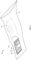
- FIG. 4 is a perspective view of an outer surface of the ostomy appliance 10 having the filter assembly 110 according to an embodiment.
- FIG. 5 is a cut-away perspective view showing an interior of the ostomy appliance 10 having the filter assembly 110 according to an embodiment.
- the filter assembly 110 is disposed relative to the pouch wall 14 such that at least the bypass venting chamber 112 and the valve 116 are disposed within the pouch wall 14.
- the valve 116 may be operated by applying a force to pouch wall 14 in the vicinity of the valve body 120 such that the force is transmitted to the valve body 120. For example, as shown in FIG. 4 , a force may be applied to a first section 18 on an outer surface of the pouch wall 12 to actuate the valve 116.
- FIG. 6 shows the valve 116, including a valve body 120 formed as a bulb-shaped portion, according to an embodiment.
- the filter assembly 110 may include a bulb check valve 116. Active venting of gas from inside the ostomy appliance to the atmosphere may be accommodated through a filter having a hydrophobic membrane.
- the filter assembly 110 may include a bypass of the interior hydrophobic membrane in case of occlusion. In an embodiment, the bypass may be performed by manual operation of the valve 116. In this manner, gas may be vented through the filter along different path to bypass the occluded section.
- the filter assembly 110 may include portions of the pouch wall 12, i.e., pouch surfaces.
- the pouch surfaces 12 may be specifically contoured for each of access to operate the valve 116, for example, to squeeze the bulb portion.
- the filter assembly may be attached to the ostomy appliance using known techniques, e.g., heat sealing.
Landscapes
- Health & Medical Sciences (AREA)
- Epidemiology (AREA)
- Nursing (AREA)
- Orthopedic Medicine & Surgery (AREA)
- Engineering & Computer Science (AREA)
- Biomedical Technology (AREA)
- Heart & Thoracic Surgery (AREA)
- Vascular Medicine (AREA)
- Life Sciences & Earth Sciences (AREA)
- Animal Behavior & Ethology (AREA)
- General Health & Medical Sciences (AREA)
- Public Health (AREA)
- Veterinary Medicine (AREA)
- Orthopedics, Nursing, And Contraception (AREA)
Description
- The following description relates to an ostomy appliance having a filter assembly with bypass venting.
- Known ostomy bags include a filter arranged at a wall of the bag to vent and deodorize gas from inside the bag to the atmosphere. However, the filter may become partially or completely occluded, for example, by effluent within the bag. An occluded filter may restrict venting of the gas through the filter and pressure may accumulate in the bag. This may lead to undesirable ballooning of the bag.
-
EP1101462A1 discloses an ostomy pouch used by colostomy and ileostomy patients to receive bodily waste from a stoma the pouch comprises a bag (10), an inlet aperture (12) surrounded by an adhesive attachment collar (11), and a valve assembly (17) for venting gas from the bag. The valve means comprises an outer resilient frusto-conical diaphragm (18) integrally formed with a resilient inner cylindrical core (19) having a slot (20) cut in its wall. By squeezing the outer diaphragm (18) the inner core (19) is distorted to cause the slot (20) to open and release gas from within the bag, through a filter (15) to atmosphere. The valve assembly (17) enables the bag to be vented at will and thus provides user control to prevent ballooning and pancaking of the bag. -
EP 0116363 A1 , which discloses the preamble ofclaim 1, shows a colostomy bag having a device for filtration and controlled discharge of malodorous intestinal gases and having a separate filter chamber (10) which is to receive a filter material (11) and which has a gas outlet port (12) leading into the open and is connected via a gas inlet port (13), closed by means of a manually operable valve (16), to the interior (8) of the bag receiving the intestinal excretions, characterized in that the device for filtration and controlled discharge of the intestinal gases is integrated into the bag as a result of the filter chamber (10) being provided in the bag and being directly connected via the valve (16) to the remainder of the interior (8) of the bag. -
US5693035A discloses an ostomy pouch in which a flexible, shape-recoverable plastic dome is secured internally to a wall of the pouch over a vent opening. A peripheral portion of the dome spaced from the apex is provided with at least one slit therethrough traversing a radially and axially extending plane of the dome. The slit is curved or arched towards the apex and defines outer and inner lips that normally have their opposing edges in juxtaposition to restrain the escape of gases from the pouch but permit such escape in quantity when the apical portion of the dome is depressed (by axially squeezing the dome). The lips advantageously have beveled opposing surfaces with the surface of the outer lip generally facing towards the vent opening and that of the inner lip generally facing away from the vent opening. A stop element projects from the apical portion within the dome and is engagable with a deodorizing gas filter located at the base of the dome to limit the extent of deformation of the dome, and to prevent occlusion of the filter by the reverted apical portion of the dome, when the dome is pressed inwardly to open the valve. - Accordingly, it is desirable to provide an ostomy appliance, such as an ostomy pouch, having a filter assembly configured to provide for bypass venting of gas to the atmosphere.
- In one embodiment, an ostomy appliance includes a pouch wall defining at least a portion of a collection chamber configured to collect and store effluent from a stoma, an inlet formed in the pouch wall configured to be secured around the stoma and a filter assembly including filter, a valve and a bypass venting chamber extending between the filter and the valve. The filter includes an active gas inlet section configured to receive gas from the collection chamber, a bypass gas inlet section configured to receive gas through the valve, and a filter outlet section for exiting gas to the atmosphere.
- The valve may be operable between a closed configuration in which gas flow from the collection chamber to the bypass venting chamber through the valve is restricted, and an open configuration in which the collection chamber and the bypass venting chamber are in fluid communication with one another such that gas may be received in the bypass venting chamber from the collection chamber through the valve. In one embodiment, the valve may be a check valve. In one embodiment, the valve may include a resilient valve body and a flow control portion movable between a closed condition corresponding to the closed configuration of the valve and an open condition corresponding to the open configuration of the valve. In one embodiment, the valve body may urge the flow control portion to the closed condition. In one embodiment, the filter maybe at least partially disposed in the bypass venting chamber. In one embodiment, the bypass venting chamber may include at least a portion of the pouch wall. In one embodiment, the filter may include hydrophobic membrane.
- Other objects, features, and advantages of the disclosure will be apparent from the following description, taken in conjunction with the accompanying sheets of drawings, wherein like numerals refer to like parts, elements, components, steps, and processes.
-
-
FIG. 1 is a plan view showing a portion of an ostomy appliance having a filter assembly with bypass venting according to an embodiment; -
FIG. 2 is a perspective view of the filter assembly with bypass venting according to an embodiment; -
FIG. 3 is a cross-sectional side view of the filter assembly with bypass venting according to an embodiment; -
FIG. 4 is a perspective view of an ostomy appliance having a filter assembly with bypass venting according to an embodiment; -
FIG. 5 is a cut-away perspective view showing an interior of an ostomy appliance having a filter assembly with bypass venting according to an embodiment; and -
FIG. 6 shows an example of a valve for use with a filter assembly having bypass venting according to an embodiment. - While the present disclosure is susceptible of embodiment in various forms, there is shown in the drawings and will hereinafter be described one or more embodiments with the understanding that the present disclosure is to be considered illustrative only and is not intended to limit the disclosure to any specific embodiment described or illustrated.
-
FIG. 1 is a plan view showing a portion of anostomy appliance 10 having afilter assembly 110 with abypass venting chamber 112, according to an embodiment. Theostomy appliance 10 may be an ostomy pouch configured to be secured to a user in a known manner. Theostomy appliance 10 includes apouch wall 12 defining at least a portion of acollection chamber 14 within theostomy appliance 10 configured to receive and store effluent discharged from a stoma. Astoma inlet opening 16 is formed in thepouch wall 12 and is configured to be fitted around the stoma when the ostomy appliance is secured to the user. -
FIG. 2 is a perspective view of thefilter assembly 110 according to an embodiment.FIG. 3 is a cross-sectional side view of thefilter assembly 110 according to an embodiment. Thefilter assembly 110 includes afilter 114 and avalve 116 fluidically connected to one another by thebypass venting chamber 112. Thebypass venting chamber 112 may be formed, for example, by a housing, barrier, membrane or other similar structure connected to and extending between thefilter 114 and thevalve 116. In one embodiment, at least a portion of thebypass venting chamber 112 may be formed by thepouch wall 12. - In one embodiment, the
filter 114 may be a porous, gas-permeable filter configured to deodorize a gas flowing through thefilter 114. Examples of such filters include known carbon filters commonly used in ostomy appliances. Thefilter 114 may include a hydrophobic membrane so that thefilter 114 is substantially liquid impermeable. In one embodiment, thefilter 114 may be at least partially disposed in thebypass venting chamber 112. Thefilter 114 includes afilter outlet section 118 through which a filtered gas may exit and be released to the atmosphere. - The
valve 116 includes avalve body 120 and aflow control portion 122 configured to be operated between a closed condition and an open condition. In one embodiment, thevalve 116 may be a check valve. In one embodiment, thevalve body 120 may be a substantially resilient body, and theflow control portion 122 may be a valve slit formed in thevalve body 120. - Referring to
FIG. 3 , thefilter 114 further includes an activegas inlet section 124 and a bypassgas inlet section 126. Thefilter 114 is configured to receive unfiltered gas from thecollection chamber 14 through the activegas inlet section 124. Thefilter 114 is also configured to receive unfiltered gas from thebypass venting chamber 112 through the bypassgas inlet section 126. - The
valve 116 is operable between a closed configuration in which flow of unfiltered gas from thecollection chamber 14 into thebypass venting chamber 112 through thevalve 116 is substantially prevented, and an open configuration in which flow of unfiltered gas from thecollection chamber 14 into thebypass venting chamber 112 through the valve is permitted. In one embodiment, thevalve 116 may be actuated, i.e., moved from the closed configuration to the open configuration, by applying a force to thevalve body 120, for example, by manually squeezing thevalve body 120, by a gas pressure within thecollection chamber 14, or by a specific actuating tool on thevalve 116 or a tool configured for use with thevalve 116. In one embodiment, thevalve 116 may be moved from the open configuration to the closed configuration by a applying a force in a direction opposite to that described above for moving the valve to the open configuration. In one embodiment, thevalve 116 may be resiliently urged to one of the open configuration or the closed configuration such that thevalve 116 is normally open or normally closed. - In one embodiment, the
valve body 120 is a bulb-shaped portion made of a resilient material and theflow control portion 122 is a valve slit resiliently urged to a closed condition, corresponding to the closed configuration of thevalve 116. A force, such as a manual squeezing force, may be applied to thevalve body 120 to move thevalve 116 to the open configuration by moving theflow control portion 122 to the open condition. Thevalve 116 may be returned to the closed configuration by releasing the squeezing force, allowing theflow control portion 122 to return to the closed condition under the resiliency of thevalve body 120. - It will be appreciated that the present disclosure is not limited to the example described above and shown in
FIGS. 2 and3 . For example, the force applied to thevalve 116 may be a one-way directional force, for example, from a gas pressure in thecollection chamber 14. Thevalve body 120 may elastically deform to move theflow control portion 122 to the open condition if the force exceeds a predetermined value. Theflow control portion 122 may return to the closed condition when the force, e.g., gas pressure, in thecollection chamber 14 falls below the predetermined value. - The
filter assembly 110 may be installed or formed in theostomy appliance 10 at thepouch wall 12. According to one embodiment, in an active venting state, unfiltered gas in thecollection chamber 14 flows toward thefilter 114 along active gas path AGP and is received in thefilter 114 through the activegas inlet section 124. The gas may then flow through thefilter 114 along filter gas path FGP where the gas is filtered (i.e., deodorized). The filtered gas may then exit thefilter 114 through thefilter outlet section 118 to the atmosphere along exit gas path EGP. - Occlusion of the active
gas inlet section 124 of thefilter 114 by effluent in thecollection chamber 14 may restrict flow of gas into thefilter 114 through the activegas inlet section 124 and cause gas pressure to accumulate in thecollection chamber 14. To vent gas from thecollection chamber 14, thevalve 116 may be actuated to the open configuration so that thebypass venting chamber 112 is in fluid communication with, and receives unfiltered gas from, thecollection chamber 14 through thevalve 116. For example, with thevalve 116 in the open configuration, i.e., with theflow control portion 122 in the open condition, the unfiltered gas from thecollection chamber 14 may flow through theflow control portion 122 into thevalve 116 along valve gas path VGP. The unfiltered gas may then flow into thebypass venting chamber 112 to thefilter 114 along bypass gas path BGP, and into thefilter 114 through the bypassgas inlet section 126. The gas may then flow through thefilter 114 along the filter gas path FGP and exit thefilter 114 throughfilter outlet section 118 to the atmosphere along the exit gas path EGP in the manner described above. - Accordingly, in the examples above, undesirable gas pressure in the
ostomy appliance 10 resulting from an occluded filter inlet section may be substantially relieved or avoided by operation of thevalve 116, which allows unfiltered gas to bypass the occluded section of thefilter 114. -
FIG. 4 is a perspective view of an outer surface of theostomy appliance 10 having thefilter assembly 110 according to an embodiment.FIG. 5 is a cut-away perspective view showing an interior of theostomy appliance 10 having thefilter assembly 110 according to an embodiment. In one embodiment, thefilter assembly 110 is disposed relative to thepouch wall 14 such that at least thebypass venting chamber 112 and thevalve 116 are disposed within thepouch wall 14. Thus, in one embodiment, thevalve 116 may be operated by applying a force topouch wall 14 in the vicinity of thevalve body 120 such that the force is transmitted to thevalve body 120. For example, as shown inFIG. 4 , a force may be applied to afirst section 18 on an outer surface of thepouch wall 12 to actuate thevalve 116. -
FIG. 6 shows thevalve 116, including avalve body 120 formed as a bulb-shaped portion, according to an embodiment. - In some embodiments, the
filter assembly 110 may include abulb check valve 116. Active venting of gas from inside the ostomy appliance to the atmosphere may be accommodated through a filter having a hydrophobic membrane. Thefilter assembly 110 may include a bypass of the interior hydrophobic membrane in case of occlusion. In an embodiment, the bypass may be performed by manual operation of thevalve 116. In this manner, gas may be vented through the filter along different path to bypass the occluded section. - In an alternate embodiment, the
filter assembly 110 may include portions of thepouch wall 12, i.e., pouch surfaces. The pouch surfaces 12 may be specifically contoured for each of access to operate thevalve 116, for example, to squeeze the bulb portion. The filter assembly may be attached to the ostomy appliance using known techniques, e.g., heat sealing. - It is understood that the relative directions described above, e.g, "upward," "downward," "upper," "lower," "above," "below," are used for illustrative purposes only and may change depending on an orientation of the ostomy pouch and/or the patient. Accordingly, this terminology is non-limiting in nature. In addition, it is understood that one or more various features of an embodiment above may be used in, combined with, or replace other features of a different embodiment described herein.
- All patents referred to herein, are hereby incorporated herein in their entirety, by reference, whether or not specifically indicated as such within the text of this disclosure.
- In the present disclosure, the words "a" or "an" are to be taken to include both the singular and the plural. Conversely, any reference to plural items shall, where appropriate, include the singular.
- From the foregoing it will be observed that numerous modifications and variations can be effectuated without departing from the scope of the novel concepts of the present invention. It is to be understood that no limitation with respect to the specific embodiments illustrated is intended or should be inferred. The disclosure is intended to cover by the appended claims all such modifications as fall within the scope of the claims.
Claims (7)
- An ostomy appliance (10) comprising:a pouch wall (12) defining at least a portion of a collection chamber (14) configured to collect and store effluent from a stoma;an inlet (16) formed in the pouch wall configured to be secured around the stoma; anda filter assembly (110) comprising filter (114), a valve (116) and a bypass venting chamber (112) extending between the filter and the valve, the filter comprising an active gas inlet section (124) configured to receive gas from the collection chamber, a bypass gas inlet section (126) configured to receive gas through the valve, and a filter outlet section (118) for exiting gas to the atmosphere, wherein the valve (116) is operable between a closed configuration in which gas flow from the collection chamber to the bypass venting chamber (112) through the valve is restricted, and an open configuration in which the collection chamber (14) and the bypass venting chamber (112) are in fluid communication with one another such that gas is received in the bypass venting chamber from the collection chamber through the valve characterized in thatwhen the filter assembly (110) is in an active venting state, the valve (116) is in the closed configuration and gas in the collection chamber (14) flows through the active gas inlet section (124) and through the filter (114) and exits the filter through the filter outlet section (118).
- The ostomy appliance (10) of claim 1, wherein the valve (116) is a check valve.
- The ostomy appliance (10) of claim 1, wherein the valve (116) comprises a resilient valve body (120) and a flow control portion (122) movable between a closed condition corresponding to the closed configuration of the valve and an open condition corresponding to the open configuration of the valve.
- The ostomy appliance (10) of claim 3, wherein the valve body (120) urges the flow control portion (122) to the closed condition.
- The ostomy appliance (10) of claim 1, wherein the filter (114) is at least partially disposed in the bypass venting chamber (112).
- The ostomy appliance (10) of claim 1, wherein the bypass venting chamber (112) includes at least a portion of the pouch wall (12).
- The ostomy appliance (10) of claim 1, wherein the filter (114) includes a hydrophobic membrane.
Priority Applications (1)
| Application Number | Priority Date | Filing Date | Title |
|---|---|---|---|
| EP23214035.0A EP4324436A3 (en) | 2019-11-08 | 2020-10-12 | Ostomy appliance and filter assembly with bypass venting |
Applications Claiming Priority (2)
| Application Number | Priority Date | Filing Date | Title |
|---|---|---|---|
| US201962933064P | 2019-11-08 | 2019-11-08 | |
| PCT/US2020/055244 WO2021091658A1 (en) | 2019-11-08 | 2020-10-12 | Ostomy appliance and filter assembly with bypass venting |
Related Child Applications (1)
| Application Number | Title | Priority Date | Filing Date |
|---|---|---|---|
| EP23214035.0A Division EP4324436A3 (en) | 2019-11-08 | 2020-10-12 | Ostomy appliance and filter assembly with bypass venting |
Publications (2)
| Publication Number | Publication Date |
|---|---|
| EP4054493A1 EP4054493A1 (en) | 2022-09-14 |
| EP4054493B1 true EP4054493B1 (en) | 2023-12-06 |
Family
ID=73040325
Family Applications (2)
| Application Number | Title | Priority Date | Filing Date |
|---|---|---|---|
| EP20800474.7A Active EP4054493B1 (en) | 2019-11-08 | 2020-10-12 | Ostomy appliance and filter assembly with bypass venting |
| EP23214035.0A Pending EP4324436A3 (en) | 2019-11-08 | 2020-10-12 | Ostomy appliance and filter assembly with bypass venting |
Family Applications After (1)
| Application Number | Title | Priority Date | Filing Date |
|---|---|---|---|
| EP23214035.0A Pending EP4324436A3 (en) | 2019-11-08 | 2020-10-12 | Ostomy appliance and filter assembly with bypass venting |
Country Status (5)
| Country | Link |
|---|---|
| US (1) | US20240065876A1 (en) |
| EP (2) | EP4054493B1 (en) |
| DK (1) | DK4054493T3 (en) |
| LT (1) | LT4054493T (en) |
| WO (1) | WO2021091658A1 (en) |
Family Cites Families (5)
| Publication number | Priority date | Publication date | Assignee | Title |
|---|---|---|---|---|
| DE3304312C1 (en) * | 1983-02-09 | 1984-06-14 | Sorbexx GmbH Gesellschaft für Adsorptionstechnik und Verbundstoffe, 8586 Gefrees | Colostomy bag with a device for filtering and controlled removal of the gases |
| US5693035A (en) * | 1996-11-21 | 1997-12-02 | Hollister Incorporated | Vented ostomy pouch and self-closing valve therefor |
| GB9927135D0 (en) * | 1999-11-17 | 2000-01-12 | Wood Michael | Ostomy patches |
| US7326190B2 (en) * | 2005-05-25 | 2008-02-05 | Hollister Incorporated | Ostomy pouch and high performance deodorizing gas filter assembly therefor |
| US9101483B2 (en) * | 2010-11-08 | 2015-08-11 | Coloplast A/S | Ostomy bag with intermediate filter element |
-
2020
- 2020-10-12 EP EP20800474.7A patent/EP4054493B1/en active Active
- 2020-10-12 EP EP23214035.0A patent/EP4324436A3/en active Pending
- 2020-10-12 US US17/766,681 patent/US20240065876A1/en active Pending
- 2020-10-12 DK DK20800474.7T patent/DK4054493T3/en active
- 2020-10-12 WO PCT/US2020/055244 patent/WO2021091658A1/en active Application Filing
- 2020-10-12 LT LTEPPCT/US2020/055244T patent/LT4054493T/en unknown
Also Published As
| Publication number | Publication date |
|---|---|
| DK4054493T3 (en) | 2024-02-05 |
| EP4054493A1 (en) | 2022-09-14 |
| LT4054493T (en) | 2024-02-12 |
| EP4324436A2 (en) | 2024-02-21 |
| EP4324436A3 (en) | 2024-05-01 |
| WO2021091658A1 (en) | 2021-05-14 |
| US20240065876A1 (en) | 2024-02-29 |
Similar Documents
| Publication | Publication Date | Title |
|---|---|---|
| US8092437B2 (en) | Controlled evacuation ostomy device with external seal | |
| US5643234A (en) | Ostomy bag with multi-stage filter | |
| EP0607028B1 (en) | Ostomy bag with multi-stage filter | |
| US5626569A (en) | Device for venting and controlling the pressure inside a stoma collection bag | |
| EP0981311B1 (en) | An ostomy appliance | |
| US5185007A (en) | Suction drainage infection control system | |
| JP4369242B2 (en) | Hole making tool | |
| JPH07289573A (en) | Ostomy pouch | |
| US4479818A (en) | Surgical drainage bags | |
| US4232672A (en) | Ostomy coupling including a venting valve | |
| JP4571265B2 (en) | A pressure relief valve for a faux sack, a second bag for use in a sachet, a sachet, and a stool | |
| JP3529745B2 (en) | Excrement containment equipment | |
| CA2458755A1 (en) | An ostomy appliance | |
| EP1922039A2 (en) | Adsorbent ostomy bag vent | |
| GB2094153A (en) | Colostomy appliance and pressure relief valve therefor | |
| CA2211814A1 (en) | Vented ostomy pouch and self-closing valve therefor | |
| EP3075362B1 (en) | Ostomy bag for extended wear | |
| CA1188180A (en) | Venting assembly for a sealed body fluid drainage device | |
| EP4054493B1 (en) | Ostomy appliance and filter assembly with bypass venting | |
| US6007525A (en) | Filtering and deodorizing device for use with colostomy pouch | |
| US11806269B2 (en) | Ostomy bag vent system for use in venting a gas from an interior of an ostomy collection pouch | |
| EP1101462A1 (en) | Ostomy pouches | |
| US20240065877A1 (en) | Ostomy bag vent system for use in venting a gas from an interior of an ostomy collection pouch | |
| US20230070877A1 (en) | Ostomy appliance and cleanable filter assembly |
Legal Events
| Date | Code | Title | Description |
|---|---|---|---|
| STAA | Information on the status of an ep patent application or granted ep patent |
Free format text: STATUS: UNKNOWN |
|
| STAA | Information on the status of an ep patent application or granted ep patent |
Free format text: STATUS: THE INTERNATIONAL PUBLICATION HAS BEEN MADE |
|
| PUAI | Public reference made under article 153(3) epc to a published international application that has entered the european phase |
Free format text: ORIGINAL CODE: 0009012 |
|
| STAA | Information on the status of an ep patent application or granted ep patent |
Free format text: STATUS: REQUEST FOR EXAMINATION WAS MADE |
|
| 17P | Request for examination filed |
Effective date: 20220406 |
|
| AK | Designated contracting states |
Kind code of ref document: A1 Designated state(s): AL AT BE BG CH CY CZ DE DK EE ES FI FR GB GR HR HU IE IS IT LI LT LU LV MC MK MT NL NO PL PT RO RS SE SI SK SM TR |
|
| DAV | Request for validation of the european patent (deleted) | ||
| DAX | Request for extension of the european patent (deleted) | ||
| P01 | Opt-out of the competence of the unified patent court (upc) registered |
Effective date: 20230520 |
|
| GRAP | Despatch of communication of intention to grant a patent |
Free format text: ORIGINAL CODE: EPIDOSNIGR1 |
|
| STAA | Information on the status of an ep patent application or granted ep patent |
Free format text: STATUS: GRANT OF PATENT IS INTENDED |
|
| INTG | Intention to grant announced |
Effective date: 20230915 |
|
| RAP3 | Party data changed (applicant data changed or rights of an application transferred) |
Owner name: HOLLISTER INCORPORATED |
|
| GRAS | Grant fee paid |
Free format text: ORIGINAL CODE: EPIDOSNIGR3 |
|
| GRAA | (expected) grant |
Free format text: ORIGINAL CODE: 0009210 |
|
| STAA | Information on the status of an ep patent application or granted ep patent |
Free format text: STATUS: THE PATENT HAS BEEN GRANTED |
|
| AK | Designated contracting states |
Kind code of ref document: B1 Designated state(s): AL AT BE BG CH CY CZ DE DK EE ES FI FR GB GR HR HU IE IS IT LI LT LU LV MC MK MT NL NO PL PT RO RS SE SI SK SM TR |
|
| REG | Reference to a national code |
Ref country code: GB Ref legal event code: FG4D |
|
| REG | Reference to a national code |
Ref country code: DE Ref legal event code: R096 Ref document number: 602020022402 Country of ref document: DE |
|
| REG | Reference to a national code |
Ref country code: CH Ref legal event code: EP |
|
| REG | Reference to a national code |
Ref country code: IE Ref legal event code: FG4D |
|
| REG | Reference to a national code |
Ref country code: DK Ref legal event code: T3 Effective date: 20240202 |
|
| REG | Reference to a national code |
Ref country code: NL Ref legal event code: FP |
|
| REG | Reference to a national code |
Ref country code: SE Ref legal event code: TRGR |
|
| PG25 | Lapsed in a contracting state [announced via postgrant information from national office to epo] |
Ref country code: GR Free format text: LAPSE BECAUSE OF FAILURE TO SUBMIT A TRANSLATION OF THE DESCRIPTION OR TO PAY THE FEE WITHIN THE PRESCRIBED TIME-LIMIT Effective date: 20240307 |
|
| PG25 | Lapsed in a contracting state [announced via postgrant information from national office to epo] |
Ref country code: ES Free format text: LAPSE BECAUSE OF FAILURE TO SUBMIT A TRANSLATION OF THE DESCRIPTION OR TO PAY THE FEE WITHIN THE PRESCRIBED TIME-LIMIT Effective date: 20231206 |
|
| PG25 | Lapsed in a contracting state [announced via postgrant information from national office to epo] |
Ref country code: GR Free format text: LAPSE BECAUSE OF FAILURE TO SUBMIT A TRANSLATION OF THE DESCRIPTION OR TO PAY THE FEE WITHIN THE PRESCRIBED TIME-LIMIT Effective date: 20240307 Ref country code: ES Free format text: LAPSE BECAUSE OF FAILURE TO SUBMIT A TRANSLATION OF THE DESCRIPTION OR TO PAY THE FEE WITHIN THE PRESCRIBED TIME-LIMIT Effective date: 20231206 Ref country code: BG Free format text: LAPSE BECAUSE OF FAILURE TO SUBMIT A TRANSLATION OF THE DESCRIPTION OR TO PAY THE FEE WITHIN THE PRESCRIBED TIME-LIMIT Effective date: 20240306 |
|
| REG | Reference to a national code |
Ref country code: AT Ref legal event code: MK05 Ref document number: 1637698 Country of ref document: AT Kind code of ref document: T Effective date: 20231206 |