EP4054288A1 - Heater status monitor - Google Patents
Heater status monitor Download PDFInfo
- Publication number
- EP4054288A1 EP4054288A1 EP22160102.4A EP22160102A EP4054288A1 EP 4054288 A1 EP4054288 A1 EP 4054288A1 EP 22160102 A EP22160102 A EP 22160102A EP 4054288 A1 EP4054288 A1 EP 4054288A1
- Authority
- EP
- European Patent Office
- Prior art keywords
- heater
- circuit
- controller
- appliance
- current leakage
- Prior art date
- Legal status (The legal status is an assumption and is not a legal conclusion. Google has not performed a legal analysis and makes no representation as to the accuracy of the status listed.)
- Withdrawn
Links
- 230000004044 response Effects 0.000 claims abstract description 9
- 238000000034 method Methods 0.000 claims description 12
- 239000004020 conductor Substances 0.000 description 10
- 230000007935 neutral effect Effects 0.000 description 7
- 238000001514 detection method Methods 0.000 description 4
- 238000010586 diagram Methods 0.000 description 4
- 239000003990 capacitor Substances 0.000 description 2
- 230000008569 process Effects 0.000 description 2
- 230000009286 beneficial effect Effects 0.000 description 1
- 230000007423 decrease Effects 0.000 description 1
- 230000003247 decreasing effect Effects 0.000 description 1
- 238000005516 engineering process Methods 0.000 description 1
- 238000009413 insulation Methods 0.000 description 1
- 230000004048 modification Effects 0.000 description 1
- 238000012986 modification Methods 0.000 description 1
- 230000035939 shock Effects 0.000 description 1
- XLYOFNOQVPJJNP-UHFFFAOYSA-N water Substances O XLYOFNOQVPJJNP-UHFFFAOYSA-N 0.000 description 1
Images



Classifications
-
- H—ELECTRICITY
- H02—GENERATION; CONVERSION OR DISTRIBUTION OF ELECTRIC POWER
- H02H—EMERGENCY PROTECTIVE CIRCUIT ARRANGEMENTS
- H02H11/00—Emergency protective circuit arrangements for preventing the switching-on in case an undesired electric working condition might result
- H02H11/005—Emergency protective circuit arrangements for preventing the switching-on in case an undesired electric working condition might result in case of too low isolation resistance, too high load, short-circuit; earth fault
-
- H—ELECTRICITY
- H05—ELECTRIC TECHNIQUES NOT OTHERWISE PROVIDED FOR
- H05B—ELECTRIC HEATING; ELECTRIC LIGHT SOURCES NOT OTHERWISE PROVIDED FOR; CIRCUIT ARRANGEMENTS FOR ELECTRIC LIGHT SOURCES, IN GENERAL
- H05B1/00—Details of electric heating devices
- H05B1/02—Automatic switching arrangements specially adapted to apparatus ; Control of heating devices
- H05B1/0227—Applications
- H05B1/0252—Domestic applications
-
- G—PHYSICS
- G01—MEASURING; TESTING
- G01R—MEASURING ELECTRIC VARIABLES; MEASURING MAGNETIC VARIABLES
- G01R31/00—Arrangements for testing electric properties; Arrangements for locating electric faults; Arrangements for electrical testing characterised by what is being tested not provided for elsewhere
- G01R31/50—Testing of electric apparatus, lines, cables or components for short-circuits, continuity, leakage current or incorrect line connections
- G01R31/52—Testing for short-circuits, leakage current or ground faults
-
- A—HUMAN NECESSITIES
- A47—FURNITURE; DOMESTIC ARTICLES OR APPLIANCES; COFFEE MILLS; SPICE MILLS; SUCTION CLEANERS IN GENERAL
- A47L—DOMESTIC WASHING OR CLEANING; SUCTION CLEANERS IN GENERAL
- A47L15/00—Washing or rinsing machines for crockery or tableware
- A47L15/0018—Controlling processes, i.e. processes to control the operation of the machine characterised by the purpose or target of the control
- A47L15/0021—Regulation of operational steps within the washing processes, e.g. optimisation or improvement of operational steps depending from the detergent nature or from the condition of the crockery
-
- A—HUMAN NECESSITIES
- A47—FURNITURE; DOMESTIC ARTICLES OR APPLIANCES; COFFEE MILLS; SPICE MILLS; SUCTION CLEANERS IN GENERAL
- A47L—DOMESTIC WASHING OR CLEANING; SUCTION CLEANERS IN GENERAL
- A47L15/00—Washing or rinsing machines for crockery or tableware
- A47L15/42—Details
- A47L15/4285—Water-heater arrangements
-
- A—HUMAN NECESSITIES
- A47—FURNITURE; DOMESTIC ARTICLES OR APPLIANCES; COFFEE MILLS; SPICE MILLS; SUCTION CLEANERS IN GENERAL
- A47L—DOMESTIC WASHING OR CLEANING; SUCTION CLEANERS IN GENERAL
- A47L15/00—Washing or rinsing machines for crockery or tableware
- A47L15/42—Details
- A47L15/4287—Temperature measuring or regulating arrangements
-
- G—PHYSICS
- G01—MEASURING; TESTING
- G01R—MEASURING ELECTRIC VARIABLES; MEASURING MAGNETIC VARIABLES
- G01R31/00—Arrangements for testing electric properties; Arrangements for locating electric faults; Arrangements for electrical testing characterised by what is being tested not provided for elsewhere
- G01R31/50—Testing of electric apparatus, lines, cables or components for short-circuits, continuity, leakage current or incorrect line connections
- G01R31/66—Testing of connections, e.g. of plugs or non-disconnectable joints
- G01R31/67—Testing the correctness of wire connections in electric apparatus or circuits
-
- H—ELECTRICITY
- H02—GENERATION; CONVERSION OR DISTRIBUTION OF ELECTRIC POWER
- H02H—EMERGENCY PROTECTIVE CIRCUIT ARRANGEMENTS
- H02H1/00—Details of emergency protective circuit arrangements
- H02H1/0007—Details of emergency protective circuit arrangements concerning the detecting means
-
- H—ELECTRICITY
- H05—ELECTRIC TECHNIQUES NOT OTHERWISE PROVIDED FOR
- H05B—ELECTRIC HEATING; ELECTRIC LIGHT SOURCES NOT OTHERWISE PROVIDED FOR; CIRCUIT ARRANGEMENTS FOR ELECTRIC LIGHT SOURCES, IN GENERAL
- H05B2203/00—Aspects relating to Ohmic resistive heating covered by group H05B3/00
- H05B2203/035—Electrical circuits used in resistive heating apparatus
Definitions
- the present disclosure relates to a system and method to detecting current leakage of a heater in an appliance.
- Known detection circuits, components, etc. are not configured to detect current leakage from the circuit regardless of whether the input source has normal polarity or reversed polarity (i.e., Neutral-Line), which may occur in various situations, such as where the source (e.g., home) electrical grid lines are reversed from normal polarity.
- normal polarity or reversed polarity i.e., Neutral-Line
- An appliance having a heater connectable to a power source to create a heater circuit includes a controller and a heater switch configured to be selectively closed in response to a control signal from the controller to complete the heater circuit and enable current to flow from the power source to the electric heater.
- the appliance further includes a heater feedback circuit comprising a plurality of resistors and configured to be connected to the power source and further configured to generate an output signal to the controller having a first state indicative of no current leakage from the heater circuit, a second state indicative of current leakage from the heater circuit where the polarity of the power source is normal, and a third state indicative of current leakage from the heater circuit where the polarity of the power source is reversed.
- the controller may determine whether current leakage exists in the heater circuit, regardless of the polarity of the grid lines from the power source. The controller may take various actions in response to such determination.
- FIG. 1 schematically illustrates an appliance 10 connected to a power source 5 with normal polarity.
- Appliance 10 includes a control board 20 connected to a heater 30.
- Line L represents the line conductor and line N represents the neutral conductor of the power source 5.
- Line PE represents the ground conductor (i.e., potential earth).
- Line L is connected to terminal L of the appliance 10 and control board 20, and line N is connected to terminal N of the appliance 10 and control board 20, thereby enabling power to be provided to the appliance 10 according to normal polarity.
- Line PE is connected to a ground terminal of the appliance 10 and heater 30.
- Figure 2 is similar to Figure 1 , except that it illustrates the appliance 10 connected to the power source 5 with reversed polarity.
- line L1 of the power source 5 is connected to terminal N of the appliance 10 and control board 20, and line N of the power source 5 is connected to terminal L of the appliance 10 and control board 20.
- Line PE is still connected to a ground terminal of appliance 10 and heater 30). The circuits, systems and methods described hereinafter accurately detect the existence of current leakage in the system between the heater 30 and the PE.
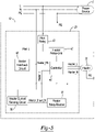
- FIG 3 schematically illustrates certain components of appliance 10 and control board 20 beneficial to explaining the system and method for detecting current leakage regardless of whether applicant 10 is connected according to Figure 1 (normal polarity) or Figure 2 (reversed polarity), as well as other conditions of the heater 30.
- Heater 30 may be connected to power source 5 via conductors Heater_L and Heater_N through a Heater Relay-Line 42 and a Heater Relay-Neutral 44, respectively.
- Pilot Relay 40 connects Heater Feedback Circuit 48 to the line conductor L of power source 5.
- Relays 40, 42 and 44 may be other types of switches as well.
- Pilot Relay 40 is ultimately responsive to an input from a user (not shown) to connect the appliance 10 to the power source 5, i.e., turning the appliance "on.”
- Heater Relay-Line 42 and Heater Relay-Neutral 44 are closed/opened in response to control signals from controller 46. Controller 46 may close Heater Relay-Line 42 and Heater Relay-Neutral 44 to supply power to heater 30 based upon the determination of certain conditions based upon input signals.
- Heater Feedback Circuit 48 is connected to line conductor L (when pilot relay 40 is closed) and Heater N conductor of power source 5. Heater Feedback Circuit 48 is configured to generate an output signal Heater_FB from which it can be determined if current leakage is present (above some threshold), regardless of whether the appliance 10 is connected according to normal polarity or reversed polarity. Heater Current Sensing Circuit 50 is connected to neutral conductor N and Heater_Shunt_N. Heater Current Sensing Circuit 50 is configured to detect if current is flowing in the heater circuit to the heater 30.
- Heater Feedback Circuit 48 Heater_FB
- Heater Current Sensing Circuit 50 Heater_I
- controller 46 determines if current is flowing to heater 30 and if there is current leakage present, regardless of the polarity of the source grid lines.
- FIG 4 schematically illustrates an embodiment of Heater Feedback Circuit 48, which functions essentially as a resistive divider circuit.
- the Heater Feedback Circuit 48 is connected to conductors Pilot_L and Heater_N, which are intended to be the power line and neutral line. If the source grid lines are configured for normal polarity, then Pilot_L and Heater_N are connected to the line L and neutral N of the power source 5, respectively, as illustrated in Figure 1 . If the source grid lines are configured for reversed polarity, then Pilot_L and Heater_N are connected to the neutral N and Line L of the power source 5, respectively, as illustrated in Figure 2 . Resisters R557 and R558 are connected in series between inputs Pilot_L and Heater_N.
- Resistor 561 is connected in series between a 5 volt source and node TP190.
- Resistors 559 and 560 are connected in series between Resistor R558 and node TP190.
- Resistor R562 and capacitor 551 are connected in series between node TP190 and ground GND.
- Diodes D1 and D2 are connected between node TP190 and ground GND and between node TP190 and a 5 volt source, respectively.
- Resistor 563 is connected in series between node TP190 and the output Heater_FB of Heater Feedback Circuit 48.
- the output Heater_FB is an analog signal that is provided to controller 46.
- the components have the following values.
- Resisters R557, R558, R559, R560 all may have values of 220K.
- Resistor R561 may be 5.6K and R562 may be 1.5K.
- Resistor R563 may be 10K.
- Capacitor 551 may be 0.001 UF.
- FIG. 5 schematically illustrates an embodiment of Heater Current Sensing Circuit 50, which functions essentially as a current sensing circuit to determine whether current is flowing.
- the output of Heater Current Sensing Circuit 50 is a binary signal indicative of whether current flow is sensed.
- Circuit 50 is a differential amplifier that amplifies the difference between the two input voltages. Both inputs are connected to the shunt resistor (R100) and the heater current creates a voltage drop on this resistor.
- the output voltage from circuit 50 is an analog signal and it is proportional to the voltage drop on shunt resistor.
- the gain is defined by the R110-R114 resistors and the bias voltage is defined by the R112 and R113 resistors.
- Figures 6 and 7 illustrate the nature of the output signal Heater_FB from Heater Feedback Circuit 48 over time, where Pilot Relay 40 is closed and Heater Relay-Line 42 and Heater Relay-Neutral 44 are open. This is a scenario in which the appliance has been turned "on,” but the heater relays have not yet been closed to permit current to flow to the heater.
- Figure 6 illustrates output signal Heater_FB where the source grid lines are configured with normal polarity
- Figure 7 illustrates output signal Heater_FB where the source grid lines are configured with reversed polarity. Illustrations 6A and 7A are the same and illustrate Heater_FB where there is no current leakage (or current leakage less than an acceptable threshold), which results in a baseline sinusoidal output signal.
- the Illustrations 6B and 7B show Heater_FB where there is approximately 50mA of current leakage.
- the amplitude of the sinusoidal output signal Heater_FB is decreased relative to the baseline sinusoidal output illustrated in Figure 6A , where the power grid is configured with normal polarity.
- the amplitude of the sinusoidal output signal Heater_FB is increased relative to the baseline sinusoidal output illustrated in Figure 7A , where the power grid is configured with reverse polarity.
- the illustrations 6C and 7C show Heater_FB where there is approximately 0.5mA of current leakage, i.e., two orders of magnitude less than the current leakage associated with illustrations 6B and 7B.
- the amplitude of the sinusoidal output signal Heater_FB is still less than the baseline sinusoidal output illustrated in illustration 6A, but not as reduced as in Figure 6B .
- the amplitude of the sinusoidal output signal Heater_FB is still greater than the baseline sinusoidal output illustrated in illustration 7A, but not as increased as that illustrated in illustration 7B.
- Figures 6 and 7 illustrate that the amplitude of the Heater_FB signal decreases relative to the amount of current leakage where the source power grid is configured with normal polarity. If the source power grid is configured with reverse polarity, then the amplitude of the Heater_FB signal increases relative to the amount of current leakage. Therefore, the controller 46 can determine from the Heater_FB signal if there is current leakage regardless of the polarity of the source grid lines.
- Controller 46 can determine various states of the heater circuit based upon a combination of the relay states and the outputs of the Heater Feedback Circuit 48 and the Heater Current Sensing Circuit 50. As previously indicated, the controller 46 can determine if current leakage is present where Pilot Relay 40 is closed and Heater Relay-Line 42 and Heater Relay-Neutral 44 are open. Where Pilot Relay 40 is closed and Heater Relay-Line 42 and Heater Relay-Neutral 44 are also closed, the controller 46 can determine if the heater is operating normally or if there is an open/broken circuit.
- the controller 46 can determine that the heater and heater circuit are operating normally. If all three relays are closed, and the Heater Current Sensing Circuit 50 indicates no current flow, then the controller 46 can determine that there is an open/broken circuit.
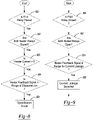
- Figure 8 illustrates steps in a method usable by controller 46 to determine if there is an open/broken circuit.
- the controller 46 determines if the pilot relay 40 is closed.
- the controller 46 determines if both heater relays 42 and 44 are closed.
- the controller 46 determines if the heater current is zero based upon the output signal Heater_L from Heater Current Sensing circuit 50.
- the controller 46 determines if the heater feedback signal Heater_FB from Heater Feedback circuit 48 is within a range known to be indicative of a disconnected circuit. If all conditions are met, then controller 46 determines at step 805 that there is an open/broken conductor in the heater circuit.
- Various actions can be taken in response to such determination, such as setting a fault code or indicator, etc.
- Figure 9 illustrates steps in a method usable by controller 46 to determine if there is current leakage in the heater circuit.
- the controller 46 determines if the pilot relay 40 is closed.
- the controller 46 determines if both heater relays 42 and 44 are open.
- the controller 46 determines if the heater feedback signal Heater_FB from Heater Feedback Circuit 48 is within a range known for current leakage, such as if the amplitude of the signal is above a threshold or below a threshold relative to a baseline amplitude. If all conditions are satisfied, then at step 906 the controller 46 determines that current leakage is present in the heater circuit.
- Various actions can be taken in response to such determination, such as setting a fault code or indicator or preventing operation of the heater until service can be provided, etc.
- Example embodiments are provided so that this disclosure will be thorough, and will fully convey the scope to those who are skilled in the art. Numerous specific details are set forth such as examples of specific components, devices, and methods, to provide a thorough understanding of embodiments of the present disclosure. It will be apparent to those skilled in the art that specific details need not be employed, that example embodiments may be embodied in many different forms and that neither should be construed to limit the scope of the disclosure. In some example embodiments, well-known processes, well-known device structures, and well-known technologies are not described in detail.
Landscapes
- Physics & Mathematics (AREA)
- General Physics & Mathematics (AREA)
- Control Of Resistance Heating (AREA)
- Testing Of Short-Circuits, Discontinuities, Leakage, Or Incorrect Line Connections (AREA)
Abstract
An appliance (10) having a heater (30) connectable to a power source (5) to create a heater circuit is disclosed. The appliance (10) includes a controller (46) and a heater switch (42, 44) configured to be selectively closed in response to a control signal from the controller (46) to complete the heater circuit and enable current to flow from the power source (5) to the electric heater (30). The appliance (10) further includes a heater feedback circuit (48) comprising a plurality of resistors and configured to be connected to the power source (5) and further configured to generate an output signal (Heater_FB) to the controller (46) having a first state indicative of no current leakage from the heater circuit, a second state indicative of current leakage from the heater circuit where the polarity of the power source is normal, and a third state indicative of current leakage from the heater circuit where the polarity of the power source is reversed. The controller (46) may determine whether current leakage exists in the heater circuit, regardless of the polarity of the grid lines from the power source (5). The controller (46) may take various actions in response to such determination.
Description
- The present disclosure relates to a system and method to detecting current leakage of a heater in an appliance.
- Various appliances, such as dishwashers and dryers, commonly incorporate electric heaters, which are used by the appliance to heat the water and dry dishes, clothes and the like. It is known that current leakage can develop in the electrical circuit connecting the heater to the power source that provides electrical current to the heater. There are a variety of causes of current leakage, including degraded wire insulation, damaged electrical components and others. Current leakage can pose a risk of electrical shock, fire hazard and other potentially undesirable consequences. Accordingly, it is known to include various detection circuits, components and the like to detect current leakage in a heater circuit. However, known detection circuits, components, etc. are generally configured to detect current leakage from a heater circuit where the polarity of the electrical input to the circuit is normal (i.e., Line-Neutral). Known detection circuits, components, etc. are not configured to detect current leakage from the circuit regardless of whether the input source has normal polarity or reversed polarity (i.e., Neutral-Line), which may occur in various situations, such as where the source (e.g., home) electrical grid lines are reversed from normal polarity.
- Therefore, it is desirable to improve the robustness of current leakage detection in appliances having electric heaters to be able to detect current leakage regardless of the polarity of the input, as well as other states of the heater operation.
- An appliance having a heater connectable to a power source to create a heater circuit is disclosed. The appliance includes a controller and a heater switch configured to be selectively closed in response to a control signal from the controller to complete the heater circuit and enable current to flow from the power source to the electric heater. The appliance further includes a heater feedback circuit comprising a plurality of resistors and configured to be connected to the power source and further configured to generate an output signal to the controller having a first state indicative of no current leakage from the heater circuit, a second state indicative of current leakage from the heater circuit where the polarity of the power source is normal, and a third state indicative of current leakage from the heater circuit where the polarity of the power source is reversed. The controller may determine whether current leakage exists in the heater circuit, regardless of the polarity of the grid lines from the power source. The controller may take various actions in response to such determination.
- Further areas of applicability will become apparent from the description provided herein. The description and specific examples in this summary are intended for purposes of illustration only and are not intended to limit the scope of the present disclosure.
- The drawings described herein are for illustrative purposes only of selected embodiments and not all possible implementations, and are not intended to limit the scope of the present disclosure.
-
FIGURE 1 schematically illustrates an appliance connected to a power source in a normal polarity configuration. -
FIGURE 2 schematically illustrates an appliance connected to a power source in a reversed polarity configuration. -
FIGURE 3 schematically illustrates additional detail of the appliance ofFIGURE 1 connected to a power source according to an embodiment. -
FIGURE 4 is a circuit diagram of an exemplary Heater Feedback Circuit, which is schematically illustrated inFIGURE 3 . -
FIGURE 5 is a circuit diagram of an exemplary Heater Current Sensing Circuit, which is schematically illustrated inFIGURE 3 . -
FIGURE 6A illustrates the output of Heater Feedback circuit having no current leakage. -
FIGURE 6B illustrates the output of Heater Feedback circuit having 50mA of current leakage to neutral. -
FIGURE 6C illustrates the output of Heater Feedback circuit having 0.5mA of current leakage to neutral. -
FIGURE 7A illustrates the output of Heater Feedback circuit having no current leakage. -
FIGURE 7B illustrates the output of Heater Feedback circuit having 50mA of current leakage to line. -
FIGURE 7C illustrates the output of Heater Feedback circuit having 0.5mA of current leakage to line. -
FIGURE 8 is a flow diagram illustrating exemplary steps in a method of determining if a heater circuit is open/broken. -
FIGURE 9 is a flow diagram illustrating exemplary steps in a method of determining if a heater circuit is experiencing current leakage. - Corresponding reference numerals indicate corresponding parts throughout the several views of the drawings.
- Example embodiments will now be described more fully with reference to the accompanying drawings.
- The foregoing description of the embodiments has been provided for purposes of illustration and description. It is not intended to be exhaustive or to limit the disclosure. Individual elements or features of a particular embodiment are generally not limited to that particular embodiment, but, where applicable, are interchangeable and can be used in a selected embodiment, even if not specifically shown or described. The same may also be varied in many ways. Such variations are not to be regarded as a departure from the disclosure, and all such modifications are intended to be included within the scope of the disclosure.
-
Figure 1 schematically illustrates anappliance 10 connected to apower source 5 with normal polarity.Appliance 10 includes acontrol board 20 connected to aheater 30. Line L represents the line conductor and line N represents the neutral conductor of thepower source 5. Line PE represents the ground conductor (i.e., potential earth). Line L is connected to terminal L of theappliance 10 andcontrol board 20, and line N is connected to terminal N of theappliance 10 andcontrol board 20, thereby enabling power to be provided to theappliance 10 according to normal polarity. Line PE is connected to a ground terminal of theappliance 10 andheater 30. -
Figure 2 is similar toFigure 1 , except that it illustrates theappliance 10 connected to thepower source 5 with reversed polarity. Here, line L1 of thepower source 5 is connected to terminal N of theappliance 10 andcontrol board 20, and line N of thepower source 5 is connected to terminal L of theappliance 10 andcontrol board 20. (Line PE is still connected to a ground terminal ofappliance 10 and heater 30). The circuits, systems and methods described hereinafter accurately detect the existence of current leakage in the system between theheater 30 and the PE. -
Figure 3 schematically illustrates certain components ofappliance 10 andcontrol board 20 beneficial to explaining the system and method for detecting current leakage regardless of whetherapplicant 10 is connected according toFigure 1 (normal polarity) orFigure 2 (reversed polarity), as well as other conditions of theheater 30.Heater 30 may be connected topower source 5 via conductors Heater_L and Heater_N through a Heater Relay-Line 42 and a Heater Relay-Neutral 44, respectively. Pilot Relay 40 connectsHeater Feedback Circuit 48 to the line conductor L ofpower source 5.Relays Relay 40 is ultimately responsive to an input from a user (not shown) to connect theappliance 10 to thepower source 5, i.e., turning the appliance "on." Heater Relay-Line 42 and Heater Relay-Neutral 44 are closed/opened in response to control signals fromcontroller 46.Controller 46 may close Heater Relay-Line 42 and Heater Relay-Neutral 44 to supply power to heater 30 based upon the determination of certain conditions based upon input signals. - One such input signal is received from Heater Feedback Circuit 48, and another such input is received from Heater Current Sensing Circuit 50. Heater Feedback Circuit 48 is connected to line conductor L (when
pilot relay 40 is closed) and Heater N conductor ofpower source 5.Heater Feedback Circuit 48 is configured to generate an output signal Heater_FB from which it can be determined if current leakage is present (above some threshold), regardless of whether theappliance 10 is connected according to normal polarity or reversed polarity. Heater Current Sensing Circuit 50 is connected to neutral conductor N and Heater_Shunt_N. Heater Current Sensing Circuit 50 is configured to detect if current is flowing in the heater circuit to theheater 30. The outputs of Heater Feedback Circuit 48 (Heater_FB) and Heater Current Sensing Circuit 50 (Heater_I), along with the known status of Heater Relay-Line 42, Heater Relay-Neutral 44, and PilotRelay 40, are used bycontroller 46 to determine if current is flowing to heater 30 and if there is current leakage present, regardless of the polarity of the source grid lines. -
Figure 4 schematically illustrates an embodiment ofHeater Feedback Circuit 48, which functions essentially as a resistive divider circuit. TheHeater Feedback Circuit 48 is connected to conductors Pilot_L and Heater_N, which are intended to be the power line and neutral line. If the source grid lines are configured for normal polarity, then Pilot_L and Heater_N are connected to the line L and neutral N of thepower source 5, respectively, as illustrated inFigure 1 . If the source grid lines are configured for reversed polarity, then Pilot_L and Heater_N are connected to the neutral N and Line L of thepower source 5, respectively, as illustrated inFigure 2 . Resisters R557 and R558 are connected in series between inputs Pilot_L and Heater_N. Resistor 561 is connected in series between a 5 volt source and node TP190. Resistors 559 and 560 are connected in series between Resistor R558 and node TP190. Resistor R562 and capacitor 551 are connected in series between node TP190 and ground GND. Diodes D1 and D2 are connected between node TP190 and ground GND and between node TP190 and a 5 volt source, respectively. Resistor 563 is connected in series between node TP190 and the output Heater_FB ofHeater Feedback Circuit 48. The output Heater_FB is an analog signal that is provided tocontroller 46. - In one particular embodiment of
Heater Feedback Circuit 48, the components have the following values. Resisters R557, R558, R559, R560 all may have values of 220K. Resistor R561 may be 5.6K and R562 may be 1.5K. Resistor R563 may be 10K. Capacitor 551 may be 0.001 UF. These component values are exemplary and other component values could be implemented with acceptable results within the scope of the invention. -
Figure 5 schematically illustrates an embodiment of HeaterCurrent Sensing Circuit 50, which functions essentially as a current sensing circuit to determine whether current is flowing. The output of HeaterCurrent Sensing Circuit 50 is a binary signal indicative of whether current flow is sensed.Circuit 50 is a differential amplifier that amplifies the difference between the two input voltages. Both inputs are connected to the shunt resistor (R100) and the heater current creates a voltage drop on this resistor. The output voltage fromcircuit 50 is an analog signal and it is proportional to the voltage drop on shunt resistor. The gain is defined by the R110-R114 resistors and the bias voltage is defined by the R112 and R113 resistors. -
Figures 6 and 7 illustrate the nature of the output signal Heater_FB fromHeater Feedback Circuit 48 over time, wherePilot Relay 40 is closed and Heater Relay-Line 42 and Heater Relay-Neutral 44 are open. This is a scenario in which the appliance has been turned "on," but the heater relays have not yet been closed to permit current to flow to the heater.Figure 6 illustrates output signal Heater_FB where the source grid lines are configured with normal polarity, andFigure 7 illustrates output signal Heater_FB where the source grid lines are configured with reversed polarity. Illustrations 6A and 7A are the same and illustrate Heater_FB where there is no current leakage (or current leakage less than an acceptable threshold), which results in a baseline sinusoidal output signal. The Illustrations 6B and 7B show Heater_FB where there is approximately 50mA of current leakage. As shown in illustration 6B, the amplitude of the sinusoidal output signal Heater_FB is decreased relative to the baseline sinusoidal output illustrated inFigure 6A , where the power grid is configured with normal polarity. Conversely, as illustrated inFigure 7B , the amplitude of the sinusoidal output signal Heater_FB is increased relative to the baseline sinusoidal output illustrated inFigure 7A , where the power grid is configured with reverse polarity. The illustrations 6C and 7C show Heater_FB where there is approximately 0.5mA of current leakage, i.e., two orders of magnitude less than the current leakage associated with illustrations 6B and 7B. As shown in illustration 6C, the amplitude of the sinusoidal output signal Heater_FB is still less than the baseline sinusoidal output illustrated in illustration 6A, but not as reduced as inFigure 6B . Similarly, as shown in illustration 7C, the amplitude of the sinusoidal output signal Heater_FB is still greater than the baseline sinusoidal output illustrated in illustration 7A, but not as increased as that illustrated in illustration 7B. -
Figures 6 and 7 illustrate that the amplitude of the Heater_FB signal decreases relative to the amount of current leakage where the source power grid is configured with normal polarity. If the source power grid is configured with reverse polarity, then the amplitude of the Heater_FB signal increases relative to the amount of current leakage. Therefore, thecontroller 46 can determine from the Heater_FB signal if there is current leakage regardless of the polarity of the source grid lines. -
Controller 46 can determine various states of the heater circuit based upon a combination of the relay states and the outputs of theHeater Feedback Circuit 48 and the HeaterCurrent Sensing Circuit 50. As previously indicated, thecontroller 46 can determine if current leakage is present wherePilot Relay 40 is closed and Heater Relay-Line 42 and Heater Relay-Neutral 44 are open. WherePilot Relay 40 is closed and Heater Relay-Line 42 and Heater Relay-Neutral 44 are also closed, thecontroller 46 can determine if the heater is operating normally or if there is an open/broken circuit. In particular, if all three relays are closed, and the output Heater_FB ofHeater Feedback Circuit 48 does not indicate current leakage, and the output of HeaterCurrent Sensing Circuit 50 indicates current flow, then thecontroller 46 can determine that the heater and heater circuit are operating normally. If all three relays are closed, and the HeaterCurrent Sensing Circuit 50 indicates no current flow, then thecontroller 46 can determine that there is an open/broken circuit. -
Figure 8 illustrates steps in a method usable bycontroller 46 to determine if there is an open/broken circuit. Atstep 800, thecontroller 46 determines if thepilot relay 40 is closed. Atstep 802, thecontroller 46 determines if both heater relays 42 and 44 are closed. Atstep 803, thecontroller 46 determines if the heater current is zero based upon the output signal Heater_L from HeaterCurrent Sensing circuit 50. Atstep 804, thecontroller 46 determines if the heater feedback signal Heater_FB fromHeater Feedback circuit 48 is within a range known to be indicative of a disconnected circuit. If all conditions are met, thencontroller 46 determines at step 805 that there is an open/broken conductor in the heater circuit. Various actions can be taken in response to such determination, such as setting a fault code or indicator, etc. -
Figure 9 illustrates steps in a method usable bycontroller 46 to determine if there is current leakage in the heater circuit. Atstep 900, thecontroller 46 determines if thepilot relay 40 is closed. Atstep 902, thecontroller 46 determines if both heater relays 42 and 44 are open. Atstep 904, thecontroller 46 determines if the heater feedback signal Heater_FB fromHeater Feedback Circuit 48 is within a range known for current leakage, such as if the amplitude of the signal is above a threshold or below a threshold relative to a baseline amplitude. If all conditions are satisfied, then at step 906 thecontroller 46 determines that current leakage is present in the heater circuit. Various actions can be taken in response to such determination, such as setting a fault code or indicator or preventing operation of the heater until service can be provided, etc. - Example embodiments are provided so that this disclosure will be thorough, and will fully convey the scope to those who are skilled in the art. Numerous specific details are set forth such as examples of specific components, devices, and methods, to provide a thorough understanding of embodiments of the present disclosure. It will be apparent to those skilled in the art that specific details need not be employed, that example embodiments may be embodied in many different forms and that neither should be construed to limit the scope of the disclosure. In some example embodiments, well-known processes, well-known device structures, and well-known technologies are not described in detail.
- The terminology used herein is for the purpose of describing particular example embodiments only and is not intended to be limiting. As used herein, the singular forms "a," "an," and "the" may be intended to include the plural forms as well, unless the context clearly indicates otherwise. The terms "comprises," "comprising," "including," and "having," are inclusive and therefore specify the presence of stated features, integers, steps, operations, elements, and/or components, but do not preclude the presence or addition of one or more other features, integers, steps, operations, elements, components, and/or groups thereof. The method steps, processes, and operations described herein are not to be construed as necessarily requiring their performance in the particular order discussed or illustrated, unless specifically identified as an order of performance. It is also to be understood that additional or alternative steps may be employed.
- When an element or layer is referred to as being "on," "engaged to," "connected to," or "coupled to" another element or layer, it may be directly on, engaged, connected or coupled to the other element or layer, or intervening elements or layers may be present. In contrast, when an element is referred to as being "directly on," "directly engaged to," "directly connected to," or "directly coupled to" another element or layer, there may be no intervening elements or layers present. Other words used to describe the relationship between elements should be interpreted in a like fashion (e.g., "between" versus "directly between," "adjacent" versus "directly adjacent," etc.). As used herein, the term "and/or" includes any and all combinations of one or more of the associated listed items.
Claims (13)
- An appliance (10), comprising:an electric heater (30) connectable to a power source (5) to create a heater circuit;a controller (46);a heater switch (42, 44) configured to be selectively closed in response to a control signal from the controller (46) to complete the heater circuit and enable current to flow from the power source (5) to the electric heater (30);a heater feedback circuit (48) comprising a plurality of resistors and configured to be connected to the power source (5) and further configured to generate an output signal (Heater_FB) to the controller (46) having a first state indicative of no current leakage from the heater circuit, a second state indicative of current leakage from the heater circuit where the polarity of the power source is normal, and a third state indicative of current leakage from the heater circuit where the polarity of the power source is reversed.
- The appliance of claim 1, wherein the appliance (10) is a dishwasher.
- The appliance of claim 1 where the heater switch (42, 44) is a relay.
- The appliance of claim 1, wherein the output signal (Heater_FB) of the heater feedback circuit (48) comprises a sinusoidal wave and wherein the amplitude of the sinusoidal wave associated with the second state is less than the amplitude of the sinusoidal wave associated with the first state, and wherein the amplitude of the sinusoidal wave associated with the third state is greater than the amplitude of the sinusoidal save associated with the first state.
- The appliance (10) of claim 1, further comprising a heater current sensing circuit (50) comprising a plurality of resistors connected to the heater circuit and configured to provide an output signal (Heater_L) to the controller (46) indicative of whether current is flowing to the heater.
- The appliance (10) of claim 1, wherein the controller (46) is configured to 'determine whether a break exists in the heater circuit based at least in part on the output signal (Heater_L) of the heater current sensing circuit (50) and the output signal (Heater_FB) of the heater feedback circuit (48).
- The appliance (10) of claim 1, wherein the controller (46) is configured to prevent operation of the heater (30) if the controller (46) determines there is current leakage in the heater circuit.
- An appliance (10), comprising:an electric heater (30) connectable to a power source (5) to create a heater circuit;a controller (46);a heater relay (42, 44) configured to be selectively closed in response to a control signal from the controller to complete the heater circuit and enable current to flow from the power source (5) to the electric heater (30);means for generating an output signal (Heater_FB) to the controller (46) having a first state indicative of no current leakage from the heater circuit, a second state indicative of current leakage from the heater circuit where the polarity of the power source is normal, and a third state indicative of current leakage from the heater circuit where the polarity of the power source (5) is reversed.
- The appliance (10) of claim 8, wherein the output signal (Heater_FB) of the means for generating an output signal comprises a sinusoidal wave and wherein the amplitude of the sinusoidal wave associated with the second state is less than the amplitude of the sinusoidal wave associated with the first state, and wherein the amplitude of the sinusoidal wave associated with the third state is greater than the amplitude of the sinusoidal save associated with the first state.
- The appliance (10) of claim 8, further comprising a means for generating an output signal (Heater_L) to the controller (46) indicative of whether current is flowing to the heater (30).
- The appliance (10) of claim 8, wherein the controller (46) is configured to determine whether a break exists in the heater circuit based at least in part on the output signal (Heater_L) of the heater current sensing circuit (50) and the output signal (Heater_FB) of the heater feedback circuit (48).
- The appliance (10) of claim 8, wherein the controller (46) is configured to prevent operation of the heater (30) if the controller (46) determines there is current leakage in the heater circuit.
- A method of controlling an appliance (10) having a heater (30) connected to a power source (5) through a heater circuit, comprising:receiving an output signal (Heater_FB) from a heater feedback circuit (48), which is connected to the heater circuit, comprising a sinusoidal wave;determining that current leakage in the heater circuit exists if the amplitude of the sinusoidal wave is less than the amplitude of a sinusoidal wave known to be indicative of no current leakage in the heater circuit;determining that current leakage in the heater circuit exists if the amplitude of the sinusoidal save is greater than the amplitude of the sinusoidal wave known to be indicative of no current leakage in the heater circuit; andpreventing operation of the heater (30) if it is determined that current leakage exists in the heater circuit.
Applications Claiming Priority (1)
| Application Number | Priority Date | Filing Date | Title |
|---|---|---|---|
| US17/190,519 US11418028B1 (en) | 2021-03-03 | 2021-03-03 | Heater status monitor |
Publications (1)
| Publication Number | Publication Date |
|---|---|
| EP4054288A1 true EP4054288A1 (en) | 2022-09-07 |
Family
ID=80628979
Family Applications (1)
| Application Number | Title | Priority Date | Filing Date |
|---|---|---|---|
| EP22160102.4A Withdrawn EP4054288A1 (en) | 2021-03-03 | 2022-03-03 | Heater status monitor |
Country Status (3)
| Country | Link |
|---|---|
| US (1) | US11418028B1 (en) |
| EP (1) | EP4054288A1 (en) |
| CN (1) | CN115032561A (en) |
Citations (2)
| Publication number | Priority date | Publication date | Assignee | Title |
|---|---|---|---|---|
| US6795285B1 (en) * | 2003-02-19 | 2004-09-21 | Whirlpool Corporation | Protective electrical circuit |
| US20160338569A1 (en) * | 2015-05-19 | 2016-11-24 | General Electric Company | Detecting current leakage in a heating element |
Family Cites Families (12)
| Publication number | Priority date | Publication date | Assignee | Title |
|---|---|---|---|---|
| IL88704A (en) * | 1988-12-16 | 1992-02-16 | Solar Wide Ind Ltd | Method and apparatus for protecting electrical systems |
| US6127747A (en) | 1999-09-16 | 2000-10-03 | Westinghouse Air Brake Technologies Corporation | Method and apparatus for detecting leakage current on a two wire DC or AC power line |
| CN100358204C (en) | 2002-09-29 | 2007-12-26 | 樱花卫厨(中国)有限公司 | Leakage protector circuit for electric water heater |
| KR20060041370A (en) | 2004-11-08 | 2006-05-12 | 엘지전자 주식회사 | Condensation Dryer with Leakage Detection |
| US8749199B2 (en) * | 2009-05-08 | 2014-06-10 | William Gibbens Redmann | Method and apparatus for charging an electric vehicle from a streetlight |
| US20120206100A1 (en) * | 2010-01-11 | 2012-08-16 | Leviton Manufacturing Co., Inc. | Electric vehicle supply equipment |
| US9948087B2 (en) * | 2010-03-08 | 2018-04-17 | Pass & Seymour, Inc. | Protective device for an electrical supply facility |
| US8339759B2 (en) * | 2010-11-29 | 2012-12-25 | Trippe Manufacturing Co. | Relocatable power tap with surge protector |
| CN104201647B (en) | 2014-09-01 | 2017-06-06 | 浙江苏泊尔家电制造有限公司 | Electric appliance casing leakage protection circuit and method |
| US10020649B2 (en) * | 2015-07-23 | 2018-07-10 | Pass & Seymour, Inc. | Protective device with self-test |
| CN109581141A (en) | 2018-12-14 | 2019-04-05 | 青岛经济技术开发区海尔热水器有限公司 | Electric leakage detection method of electric water heater and electric water heater |
| US11255921B2 (en) * | 2020-01-17 | 2022-02-22 | Brunswick Corporation | RV electrical outlet tester |
-
2021
- 2021-03-03 US US17/190,519 patent/US11418028B1/en active Active
-
2022
- 2022-03-03 EP EP22160102.4A patent/EP4054288A1/en not_active Withdrawn
- 2022-03-03 CN CN202210208112.0A patent/CN115032561A/en active Pending
Patent Citations (2)
| Publication number | Priority date | Publication date | Assignee | Title |
|---|---|---|---|---|
| US6795285B1 (en) * | 2003-02-19 | 2004-09-21 | Whirlpool Corporation | Protective electrical circuit |
| US20160338569A1 (en) * | 2015-05-19 | 2016-11-24 | General Electric Company | Detecting current leakage in a heating element |
Also Published As
| Publication number | Publication date |
|---|---|
| US11418028B1 (en) | 2022-08-16 |
| CN115032561A (en) | 2022-09-09 |
Similar Documents
| Publication | Publication Date | Title |
|---|---|---|
| US11408922B2 (en) | Method and system for detecting miswiring of a power supply for a domestic appliance | |
| CN109416382B (en) | Ground Loss Detection Circuit | |
| US9581626B2 (en) | Circuit and method for detecting zero-crossings and brownout conditions on a single phase or multi-phase system | |
| US20130258531A1 (en) | Faulty Protective Earth Ground Circuit Detection System And Method | |
| US20090206816A1 (en) | Controller for a domestic appliance, domestic appliance and associated method | |
| JPS59157983A (en) | Electric monitoring system | |
| KR20210020802A (en) | Compensation device for compensating for leakage currents | |
| JP6580249B2 (en) | Relay board and sensor device | |
| US20250149876A1 (en) | Leakage current detection and interruption device for power cord and related electrical connectors and electrical appliances | |
| KR101671087B1 (en) | Sequencer analog output unit | |
| US8440942B2 (en) | Circuit arrangement for protection of a heating element from overheating heating device and method for fused protection of the heating device | |
| EP2353485A1 (en) | An improved load driving circuit for an electrical household appliance, such as a washing machine, dishwasher or drier | |
| US11418028B1 (en) | Heater status monitor | |
| WO1991019340A1 (en) | Electrical protection devices | |
| JP4796429B2 (en) | Test device for test current generator and insulation monitoring device | |
| EP0531334B1 (en) | Electrical protection devices | |
| KR20190112850A (en) | Bus system and method for diagnosing a short circuit | |
| US20140035369A9 (en) | Power supply appliance and power supply system with an appliance such as this | |
| US6795285B1 (en) | Protective electrical circuit | |
| CN108693467A (en) | Switching device for checking switch element | |
| EP3177104B1 (en) | Diagnostic method for an electric heater | |
| US10746610B2 (en) | Safety circuit, a safety circuit operation method and an electrically operated motor comprising a safety circuit | |
| CN119726570A (en) | Solid-state circuit breaker and self-test method thereof | |
| JPH04238272A (en) | Power supply circuit with leakage current detecting function | |
| US9331470B1 (en) | Line side circuit protection system |
Legal Events
| Date | Code | Title | Description |
|---|---|---|---|
| PUAI | Public reference made under article 153(3) epc to a published international application that has entered the european phase |
Free format text: ORIGINAL CODE: 0009012 |
|
| STAA | Information on the status of an ep patent application or granted ep patent |
Free format text: STATUS: THE APPLICATION HAS BEEN PUBLISHED |
|
| AK | Designated contracting states |
Kind code of ref document: A1 Designated state(s): AL AT BE BG CH CY CZ DE DK EE ES FI FR GB GR HR HU IE IS IT LI LT LU LV MC MK MT NL NO PL PT RO RS SE SI SK SM TR |
|
| RAP3 | Party data changed (applicant data changed or rights of an application transferred) |
Owner name: WHIRLPOOL CORPORATION |
|
| STAA | Information on the status of an ep patent application or granted ep patent |
Free format text: STATUS: THE APPLICATION IS DEEMED TO BE WITHDRAWN |
|
| 18D | Application deemed to be withdrawn |
Effective date: 20230308 |