EP4053991A1 - End cover assembly, secondary battery, battery module, device, liquid injection method and device - Google Patents
End cover assembly, secondary battery, battery module, device, liquid injection method and device Download PDFInfo
- Publication number
- EP4053991A1 EP4053991A1 EP20936418.1A EP20936418A EP4053991A1 EP 4053991 A1 EP4053991 A1 EP 4053991A1 EP 20936418 A EP20936418 A EP 20936418A EP 4053991 A1 EP4053991 A1 EP 4053991A1
- Authority
- EP
- European Patent Office
- Prior art keywords
- end cover
- locking
- connecting portion
- fixing member
- hole
- Prior art date
- Legal status (The legal status is an assumption and is not a legal conclusion. Google has not performed a legal analysis and makes no representation as to the accuracy of the status listed.)
- Granted
Links
Images


Classifications
-
- H—ELECTRICITY
- H01—ELECTRIC ELEMENTS
- H01M—PROCESSES OR MEANS, e.g. BATTERIES, FOR THE DIRECT CONVERSION OF CHEMICAL ENERGY INTO ELECTRICAL ENERGY
- H01M50/00—Constructional details or processes of manufacture of the non-active parts of electrochemical cells other than fuel cells, e.g. hybrid cells
- H01M50/10—Primary casings; Jackets or wrappings
- H01M50/147—Lids or covers
- H01M50/148—Lids or covers characterised by their shape
-
- H—ELECTRICITY
- H01—ELECTRIC ELEMENTS
- H01M—PROCESSES OR MEANS, e.g. BATTERIES, FOR THE DIRECT CONVERSION OF CHEMICAL ENERGY INTO ELECTRICAL ENERGY
- H01M50/00—Constructional details or processes of manufacture of the non-active parts of electrochemical cells other than fuel cells, e.g. hybrid cells
- H01M50/10—Primary casings; Jackets or wrappings
- H01M50/183—Sealing members
- H01M50/186—Sealing members characterised by the disposition of the sealing members
-
- H—ELECTRICITY
- H01—ELECTRIC ELEMENTS
- H01M—PROCESSES OR MEANS, e.g. BATTERIES, FOR THE DIRECT CONVERSION OF CHEMICAL ENERGY INTO ELECTRICAL ENERGY
- H01M50/00—Constructional details or processes of manufacture of the non-active parts of electrochemical cells other than fuel cells, e.g. hybrid cells
- H01M50/60—Arrangements or processes for filling or topping-up with liquids; Arrangements or processes for draining liquids from casings
- H01M50/609—Arrangements or processes for filling with liquid, e.g. electrolytes
- H01M50/627—Filling ports
- H01M50/636—Closing or sealing filling ports, e.g. using lids
- H01M50/645—Plugs
-
- H—ELECTRICITY
- H01—ELECTRIC ELEMENTS
- H01M—PROCESSES OR MEANS, e.g. BATTERIES, FOR THE DIRECT CONVERSION OF CHEMICAL ENERGY INTO ELECTRICAL ENERGY
- H01M2220/00—Batteries for particular applications
- H01M2220/20—Batteries in motive systems, e.g. vehicle, ship, plane
-
- H—ELECTRICITY
- H01—ELECTRIC ELEMENTS
- H01M—PROCESSES OR MEANS, e.g. BATTERIES, FOR THE DIRECT CONVERSION OF CHEMICAL ENERGY INTO ELECTRICAL ENERGY
- H01M50/00—Constructional details or processes of manufacture of the non-active parts of electrochemical cells other than fuel cells, e.g. hybrid cells
- H01M50/10—Primary casings; Jackets or wrappings
- H01M50/147—Lids or covers
- H01M50/148—Lids or covers characterised by their shape
- H01M50/15—Lids or covers characterised by their shape for prismatic or rectangular cells
-
- H—ELECTRICITY
- H01—ELECTRIC ELEMENTS
- H01M—PROCESSES OR MEANS, e.g. BATTERIES, FOR THE DIRECT CONVERSION OF CHEMICAL ENERGY INTO ELECTRICAL ENERGY
- H01M50/00—Constructional details or processes of manufacture of the non-active parts of electrochemical cells other than fuel cells, e.g. hybrid cells
- H01M50/60—Arrangements or processes for filling or topping-up with liquids; Arrangements or processes for draining liquids from casings
-
- H—ELECTRICITY
- H01—ELECTRIC ELEMENTS
- H01M—PROCESSES OR MEANS, e.g. BATTERIES, FOR THE DIRECT CONVERSION OF CHEMICAL ENERGY INTO ELECTRICAL ENERGY
- H01M50/00—Constructional details or processes of manufacture of the non-active parts of electrochemical cells other than fuel cells, e.g. hybrid cells
- H01M50/60—Arrangements or processes for filling or topping-up with liquids; Arrangements or processes for draining liquids from casings
- H01M50/609—Arrangements or processes for filling with liquid, e.g. electrolytes
- H01M50/627—Filling ports
- H01M50/636—Closing or sealing filling ports, e.g. using lids
-
- Y—GENERAL TAGGING OF NEW TECHNOLOGICAL DEVELOPMENTS; GENERAL TAGGING OF CROSS-SECTIONAL TECHNOLOGIES SPANNING OVER SEVERAL SECTIONS OF THE IPC; TECHNICAL SUBJECTS COVERED BY FORMER USPC CROSS-REFERENCE ART COLLECTIONS [XRACs] AND DIGESTS
- Y02—TECHNOLOGIES OR APPLICATIONS FOR MITIGATION OR ADAPTATION AGAINST CLIMATE CHANGE
- Y02E—REDUCTION OF GREENHOUSE GAS [GHG] EMISSIONS, RELATED TO ENERGY GENERATION, TRANSMISSION OR DISTRIBUTION
- Y02E60/00—Enabling technologies; Technologies with a potential or indirect contribution to GHG emissions mitigation
- Y02E60/10—Energy storage using batteries
Definitions
- the present application relates to a technical filed of battery, and specifically relates to an end cover assembly, a secondary battery, a battery module, apparatus, a liquid injection method and a device therefor.
- lithium-ion and other batteries have the advantages of high energy density, high power density, multiple using cycles, and long storage time, they have been widely used in electric vehicles.
- the secondary battery includes a shell and an end cover assembly.
- the shell is configured to receive electrolyte.
- the end cover assembly is connected to the shell.
- the present application provides an end cover assembly for a secondary battery, including an end cover, provided with a through hole for injecting electrolyte, and including a connecting portion; a sealing assembly, configured to seal the through hole; and a locking-fixing member, configured to be movable relative to the connecting portion in a radial direction of the through hole, so as to realize switching between a locked state and an unlocked state of the locking-fixing member and the connecting portion, in which in the locked state, the locking-fixing member presses against the sealing assembly to restrict the end cover from being separated from the sealing assembly, and in the unlocked state, the end cover and the sealing assembly are separable to allow electrolyte to be injected from the through hole.
- the end cover assembly in the embodiments of the present application can be applied to a secondary battery, a predetermined amount of electrolyte can be injected into the secondary battery through the through hole, then the sealing assembly can seal the through hole, and finally the locking-fixing member can lock the connecting portion of the end cover. After the secondary battery is used for a predetermined period of time, the locking-fixing member unlocks the connecting portion of the end cover, and then the sealing assembly is removed to open the through hole.
- the predetermined amount of electrolyte can be replenished into the secondary battery through the through hole. After completing the electrolyte replenishment process, the sealing assembly seals the through hole, and the locking-fixing member locks the connecting portion of the end cover again, and the secondary battery can continue to be used normally.
- the secondary battery in the embodiments of the present application can be re-filled with the electrolyte after assembled, which can effectively prolong the operation life of the secondary battery.
- the embodiments of the present application provide a secondary battery including the end cover assembly as described above.
- the embodiments of the present application provide a battery module including the secondary battery as described above.
- the embodiments of the present application provides an apparatus including the secondary battery as described above for supplying electrical power.
- the embodiments of the present application provide a liquid-injection method for the secondary battery, including
- the embodiments of the present application provide a liquid-injection device, for injecting the electrolyte into the secondary battery as described above, the device including
- the embodiment of the present application provides a device using a secondary battery 30 as a power source.
- the device can be, but is not limited to, a vehicle, a ship, an aircraft or the like.
- the embodiment of the present application provides the vehicle 1 including a vehicle main body and a battery module.
- the battery module is arranged in the vehicle main body.
- the vehicle 1 may be a pure electric vehicle, a hybrid electric vehicle or an extended-range vehicle.
- the vehicle main body is provided with a driving motor electrically connected to the battery module.
- the battery module can supply electrical power to the driving motor.
- the driving motor is connected to wheels in the vehicle main body through a transmission mechanism to drive the vehicle to travel forward.
- the battery module may be horizontally arranged at a bottom of the vehicle main body.
- the battery module may be a battery pack 10.
- the battery pack 10 includes a housing and the battery module set 20 arranged in the housing.
- the number of battery module set 20 is one or more.
- One or more battery module sets 20 are arranged in the housing in array.
- the type of housing is not limited.
- the housing can be a frame-shaped housing, a disk-shaped housing, a box-shaped housing or the like.
- the housing includes a lower housing for accommodating the battery module set 20 and an upper housing covered with the lower housing.
- the upper housing and the lower housing are covered and closed with each other to form an accommodating portion for receiving the battery module set 20.
- the battery pack 10 includes the housing and a plurality of secondary batteries 30 directly arranged in the housing.
- the battery module may also be the battery module set 20, and the plurality of battery module sets 20 are arranged in the housing and mounted on the vehicle main body.
- the battery module set 20 includes the plurality of secondary batteries 30.
- the battery module set 20 includes the accommodating portion and the plurality of secondary batteries 30 located in the accommodating portion.
- the plurality of secondary batteries 30 are arranged side by side in the accommodating portion.
- the accommodating portion includes a shell and a cover plate arranged at the shell; or the accommodating portion includes side plates and end plates that are successively connected with one another to enclose; or the accommodating portion includes end plates arranged opposite each other and a band around the outside of the secondary battery 30 and the end plates.
- the applicant After noticing the problem that the operation life of the secondary battery 30 is short and the secondary battery 30 cannot be reused, the applicant has conducted the research and the analysis on the various structures of the secondary battery 30. The applicant found that there is irreversible reaction consumption of electrolyte of the secondary battery 30, resulting in a decrease in a using capacity of the secondary battery 30. At the same time, if the electrolyte can be replenished, the degree of the reduction of the capacity of the secondary battery 30 will be effectively slowed down. However, since the factors such as the safety, the sealing and the like need to be considered in an existing structural design of the secondary battery 30, the assembled secondary battery 30cannot be refilled with the electrolyte.
- the inventors has improved the structure of the secondary battery 30, and the embodiments of the present application will be further described below.
- the secondary battery 30 in the embodiments of the present application includes a shell 31 and an electrode assembly 32 arranged in the shell 31.
- the shell 31 in the embodiments of the present application has a cuboid structure or other shapes.
- the shell 31 has an internal space for receiving the electrode assembly 32 and the electrolyte, and an opening communicating with the internal space.
- the shell 31 may be made of materials such as aluminum, aluminum alloy, plastic or the like.
- the electrode assembly 32 in the embodiments of the present application can be formed by stacking or winding a first electrode sheet, a second electrode sheet and a separator located between the first electrode sheet and the second electrode sheet and serving as an insulator between the first electrode sheet and the second electrode sheet.
- the first electrode sheet is the positive electrode sheet
- the second electrode sheet is the negative electrode sheet.
- Each of the positive electrode sheet and the negative electrode sheet includes a coated region and an uncoated region.
- a positive electrode sheet active material coats the coated region of the positive electrode sheet
- a negative electrode sheet active material coats the coated region of the negative electrode sheet.
- the active material coats a current collector formed by a thin-plate metal foil, and the active material does not coat the uncoated region.
- the electrode assembly 32 includes two tabs 322 which are a positive tab and a negative tab respectively.
- the coated region of the positive electrode sheet and the coated region of the negative electrode sheet form a main body 321.
- the main body 321 has two end faces 321a arranged to be opposite to each other in a length direction, and the positive electrode tab and the negative electrode tab respectively extend beyond the two opposite end faces 321a of the main body 321 in the length direction.
- the secondary battery 30 in the embodiments of the present application further includes an end cover assembly 40 sealingly connected to the shell 31.
- the end cover assembly 40 includes an end cover 50, electrode terminal 80, an adapter component 90, sealing assembly 60 and a locking-fixing member 70.
- the electrode terminal 80 is arranged on the end cover 50.
- the electrode terminal 80 is electrically connected to the tab 322 of the electrode assembly 32 through the adapter component 90.
- the shape of the electrode terminal 80 may be square or circle, which is not limited here.
- the end cover 50 in the embodiments of the present application is provided with an electrode lead-out hole 50c.
- the electrode lead-out hole 50c penetrates the end cover 50.
- the electrode terminal 80 is arranged on the end cover 50 and covers the electrode lead-out hole 50c.
- the end cover 50 is also provided with a through hole 50a for injecting electrolyte.
- the through hole 50a and the electrode lead-out hole 50c are arranged to be spaced apart from each other.
- the end cover 50 has a connecting portion 51.
- the sealing assembly 60 is configured to seal the through hole 50a on the end cover 50.
- the locking-fixing member 70 is configured to be movable relative to the connecting portion 51 of the end cover 50 in a radial direction of the through hole 50a, so as to switch between a locked state and an unlocked state of the locking-fixing member 70 and the connecting portion 51.
- the radial direction of the through hole 50a refers to a direction perpendicular to an axial direction X of the through hole 50a.
- a predetermined amount of electrolyte can be injected into the secondary battery 30 through the through hole 50a, then the sealing assembly 60 can seal the through hole 50a, and finally the locking-fixing member 70 can lock the connecting portion 51 of the end cover 50.
- the locking-fixing member 70 unlocks the connecting portion 51 of the end cover 50, and then the sealing assembly 60 is removed to open the through hole 50a.
- the predetermined amount of electrolyte can be replenished into the secondary battery 30 through the through hole 50a.
- the sealing assembly 60 seals the through hole 50a, and the locking-fixing member 70 locks the connecting portion 51 of the end cover 50 again, and the secondary battery 30 can continue to be used normally.
- the secondary battery 30 in the embodiments of the present application can be re-filled with the electrolyte after assembled, which can effectively prolong the operation life of the secondary battery 30.
- the locking-fixing member 70 has an opening 71 and an accommodating space 72 communicating with each other.
- the connecting portion 51 is configured to enter the accommodating space 72 through the opening 71.
- the connecting portion 51 enters the accommodating space 72 through the opening 71.
- the connecting portion 51 locks the connecting portion 51.
- the connecting portion 51 can move out of the accommodating space 72 through the opening 71, so that the locking-fixing member 70 and the connecting portion 51 can be unlocked.
- a part of the locking-fixing member 70 where the opening 71 is formed has the good ability of the elastic deformation.
- the size of the opening 71 of the locking-fixing member 70 is smaller than the size of the accommodating space 72.
- the size of the opening 71 of the locking-fixing member 70 is smaller than the size of the connecting portion 51, so that when the connecting portion 51 enters the opening 71 or the connecting portion 51 moves out of the opening 71, the size of the opening 71 will become larger to provide a position to the connecting portion 51, and the connecting portion 51 can pass through the opening 71 smoothly.
- Apart of the locking-fixing member 70 where the accommodating space 72 is formed also has the good ability of the elastic deformation.
- the part of the locking-fixing member 70 where the accommodating space 72 is formed will return to an original state, so that the locking-fixing member 70 can lock the connecting portion 51 of the end cover 50 through the part of the locking-fixing member 70 where the accommodating space 72 is formed.
- the locking-fixing member 70 is not easy to move in the radial direction of the through hole 50a, so that the connecting portion 51 is not easily detached from the opening 71.
- the locking-fixing member 70 is snap-fitted with the connecting portion 51 of the end cover 50, so that the locking-fixing member 70 and the connecting portion 51 are in the locked state.
- the locking-fixing member 70 is detachably connected to the connecting portion 51 of the end cover 50 by means of the snapping connection, so that the locking-fixing member 70 and the connecting portion 51 can be quickly locked or unlocked to separate.
- the connecting portion 51 of the end cover 50 is provided with a snapping slot 511, and at least a part of the locking-fixing member 70 is located in the snapping slot 511 to restrict the locking-fixing member 70 from moving in the axial direction X of the through hole 50a.
- the secondary battery 30 may vibrate or impact in the axial direction X of the through hole 50a.
- the snapping slot 511 has a position-limiting wall 511a for resisting against the locking-fixing member 70 in the axial direction. A surface of the locking-fixing member 70 away from the end cover 50 is in contact with the position-limiting wall 511a, and the locking-fixing member 70 and the position-limiting wall 511a are in a surface-to-surface contact.
- the sealing assembly 60 includes a position-limiting member 61 and a sealing member 62.
- the sealing member 62 is arranged between the position-limiting member 61 and the end cover 50, and seals the through hole 50a.
- the locking-fixing member 70 can press against the position-limiting member 61, so that the limiting-fixing member 61 exerts a compressive stress on the sealing member 62, thereby restricting the sealing member 62 from moving in the axial direction X of the through hole 50a, so that the sealing member 62 can seal the through hole 50a.
- a part of the sealing member 62 extends into the through hole 50a, and another part of the sealing member 62 is located outside the through hole 50a.
- the part of the sealing member 62 extending into the through hole 50a is in an interference fit with the through hole 50a, and the part located outside the through hole 50a covers the through hole 50a, thereby improving the sealing performance of the sealing member 62.
- the material of the sealing member 62 may be the rubber or the silicone.
- the position-limiting member 61 includes a pressing-against portion 611 and a position-limiting portion 612.
- the pressing-against portion 611 is connected to the position-limiting portion 612 and covers at least a part of the sealing member 62. Preferably, the pressing-against portion 611 covers the entire sealing member 62. At least part of the position-limiting portion 612 is located at a side of the locking-fixing member 70 close to the end cover 50. The locking-fixing member 70 presses against the position-limiting portion 612 to restrict the end cover 50 from being separated from the sealing assembly 60.
- the locking-fixing member 70 exerts the compressive stress in the axial direction X of the through hole 50a to a surface of the position-limiting portion 612 away from the end cover 50 from a side of the position-limiting portion 612 away from the end cover 50, and the pressing-against portion 611 exerts a compressive stress in the axial direction X of the through hole 50a to the sealing member 62, so that the pressing-against portion 611 presses and fixes the sealing member 62.
- the end cover 50 further includes a body portion 52.
- the connecting portion 51 is a boss protruding from a surface of the body portion 52.
- the through hole 50a penetrates the connecting portion 51 and the body portion 52.
- At least part of the sealing member 62 is located at a side of the connecting portion 51 in the axial direction X of the through hole 50a.
- the body portion 52 has a rectangular plate-shaped structure.
- the connecting portion 51 includes a middle column-shaped portion and two columns. The two columns are located at two opposite sides of the middle column-shaped portion, that is, the middle column-shaped portion is located between the two columns.
- the through hole 50a penetrates the middle column-shaped portion.
- the snapping slots 511 are respectively formed in the two columns.
- the two columns are evenly spaced apart from each other in the peripheral direction Y of the through hole 50a.
- the locking-fixing member 70 has an annular structure.
- the locking-fixing member 70 is snap-fitted in the snapping slots 511 in the two columns, so as to be in a locked state with the connecting portion 51.
- an auxiliary tool can be used to expand the opening 71 of the locking-fixing member 70 in advance, so that the two columns can pass through the opening 71 into the accommodating space 72 or move out of the accommodating space 72 smoothly.
- the position-limiting member 61 further includes a supporting portion 613 and an accommodating slot 614.
- the supporting portion 613 is connected to the pressing-against portion 611 and the position-limiting portion 612.
- the accommodating slot 614 penetrates the supporting portion 613 in the radial direction of the through hole 50a.
- the connecting portion 51 of the end cover 50 passes through the accommodating slot 614.
- the accommodating slot 614 and the connecting portion 51 of the end cover 50 can be inserted and engaged with each other in the axial direction X of the through hole 50a.
- the part of the connecting portion 51 located outside the accommodating slot 614 is used for locking the locking-fixing member 70 and is arranged in an offset manner with the position-limiting portion 612 of the position-limiting member 61 in the peripheral direction Y of the through hole 50a.
- the position-limiting wall 511a of the snapping slot 511 is arranged on the portion of the connecting portion 51 that is located outside the accommodating slot 614.
- the position-limiting member 61 is restricted by the part of the connecting portion 51 located inside the accommodating slot 614, so that the position-limiting member 61 cannot rotate relative to the connecting portion 51.
- the sealing member 62 is placed on the connecting portion 51, and then the position-limiting member 61 is inserted and engaged with the connecting portion 51 in the axial direction X of the through hole 50a. Then, the locking-fixing member 70 is moved in the radial direction of the through hole 50a and snap-fitted with the snapping slot 511 of the connecting portion 51 to lock the locking-fixing member 70 and the connecting portion 51.
- the locking-fixing member 70 can restrict the position-limiting member 61 and the sealing member 62, and restrict the position-limiting member 61 and the sealing member 62 to move in the axial direction X of the through hole 50a.
- the locking-fixing member 70 is first moved in the radial direction of the through hole 50a and removed from the snapping slot 511 to detach the locking-fixing member 70 from the connecting portion 51. In this way, the position-limiting member 61 and the sealing member 62 are removed in the axial direction X of the through hole 50a, and the through hole 50a is exposed. The electrolyte is replenished to the secondary battery 30 through the through hole 50a.
- the end cover 50 has a concave slot 50b.
- the through hole 50a communicates with the concave slot 50b.
- At least a part of the sealing member 62 is accommodated in the concave slot 50b, so that it is beneficial to reduce the size of the end cover assembly 40 in the axial direction X of the through hole 50a, and the energy density of the secondary battery 30 can be increased.
- the concave slot 50b is arranged in the connecting portion 51 in the axial direction X of the through hole 50a, the concave slot 50b is arranged corresponding to the middle-shaped column portion.
- the connecting portion 51 is a column-shaped boss.
- the snapping slot 511 formed on the connecting portion 51 is an annular snapping slot 511.
- the locking-fixing member 70 has the annular structure with an opening 71, so that the locking-fixing member 70 can be snap-fitted into the snapping slot 511 of the connecting portion 51 at different positions.
- the through hole 50a is located outside the connecting portion 51, that is, the through hole 50a is spaced apart from the connecting portion 51 in the radial direction of the through hole 50a.
- the through hole 50a penetrates the body portion 52.
- two or more through holes 50a are arranged to be spaced apart from one another evenly around the connecting portion 51.
- Each of the position-limiting member 61 and the sealing member 62 has an annular structure.
- Each of the position-limiting member 61 and the sealing member 62 is used to be sleeved and connected with the connecting portion 51.
- the portion of the position-limiting member 61 that is located at the side of the locking-fixing member 70 close to the end cover 50 forms a position-limiting portion 612, and the pressing-against portion 611 is located at the outer periphery of the position-limiting portion 612.
- the portion of the connecting portion 51 where the snapping slot 511 is arranged passes through the position-limiting member 61, so that it is convenient for the locking-fixing member 70 to be snap-fitted and fixed to the snapping slot 511 at the side of the position-limiting member 61 away from the sealing member 62.
- the locking-fixing member 70 exerts the compressive stress in the axial direction X of the through hole 50a to the position-limiting portion 612 from the side of the position-limiting portion 612 away from the sealing member 62, so that the pressing-against portion 611 exerts the compressive stress in the axial direction X of the through hole 50a to the sealing member 62, thereby compressing and fixing the sealing member 62.
- At least a part of the sealing member 62 is arranged between the pressing-against portion 611 and the end cover 50, and seals all the through holes 50a.
- a concave slot 50b is formed on the body portion 52 of the end cover 50.
- the through hole 50a communicates with the concave slot 50b.
- the connecting portion 51 is arranged at a bottom of the concave slot 50b.
- the connecting portion 51 is the column-shaped boss protruding from the body portion 52. After the sealing member 62 is sleeved on the connecting portion 51, at least part of the sealing member 62 is accommodated in the concave slot 50b.
- the part of the sealing member 62 located in the concave slot 50b can contact with a bottom wall and a side wall of the concave slot 50b and maintain a sealing-fiting state, so that it is beneficial to improve the reliability and stability of the sealing between the sealing member 62 and the end cover 50.
- the position-limiting member 61 and the sealing member 62 are integrally located in the concave slot 50b.
- the sealing member 62 and the position-limiting member 61 are sequentially sleeved on the connecting portion 51, the locking-fixing member 70 is moved in the radial direction of the through hole 50a and snap-fitted with the snapping slot 511 of the connecting portion 51 to lock the locking-fixing member 70 and the connecting portion 51.
- the locking-fixing member 70 can restrict the position-limiting member 61 and the sealing member 62, and restrict the position-limiting member 61 and the sealing member 62 from moving in the axial direction X of the through hole 50a.
- the locking-fixing member 70 is first moved in the radial direction of the through hole 50a and removed from the snapping slot 511 to detach the locking-fixing member 70 from the connecting portion 51. In this way, the position-limiting member 61 and the sealing member 62 are removed in the axial direction X of the through hole 50a, and the through hole 50a is exposed. The electrolyte is replenished to the secondary battery 30 through the through hole 50a.
- the embodiment of the present application further provides a liquid-injection method for the secondary battery 30, including
- the locking-fixing member 70 when the electrolyte needs to be replenished to the secondary battery 30, the locking-fixing member 70 is moved toward a direction away from the connecting portion 51 in the radial direction of the through hole 50a, so that the locking-fixing member 70 and the connecting portion 51 are unlocked to separate the locking-fixing member 70 from the end cover 50, so as to perform corresponding operations on the sealing assembly 60.
- the liquid-injection method further includes: removing the sealing assembly 60 from the end cover 50, so that the through hole 50a can be opened, and the electrolyte can be replenished into the secondary battery 30 through the through hole 50a.
- the sealing assembly 60 is remounted on the end cover 50 and covers the through hole 50a. Then the locking-fixing member 70 locks the connecting portion 51, so that the sealing assembly 60 can maintain in the sealing state.
- the embodiment of the present application further provides a liquid-injection device for injecting the electrolyte into the secondary battery 30, including a liquid injection component and a detaching-and-mounting component of the locking-fixing member.
- the liquid injection component is configured to inject the electrolyte into the through hole 50a.
- the dismounting-and-mounting component of the locking-fixing member is configured to move the locking-fixing member 70 toward the direction close to the connecting portion 51 in the radial direction of the through hole 50a in the unlocked state, so that the locking-fixing member 70 locks the connecting portion 51 to restrict the end cover 50 from being separated from the sealing assembly 60.
- the dismounting-and-mounting component of the locking-fixing member is configured to move the locking-fixing member 70 toward the direction away from the connecting portion 51 in the radial direction of the through hole 50a, so that the locking-fixing member 70 and the connecting portion 51 are unlocked.
- the dismounting-and-mounting component of the locking-fixing member can move the locking-fixing member 70 in the radial direction of the through hole 50a, so that the locking-fixing member 70 and the connecting portion 51 can be switched between the locked state and the unlocked state.
- the liquid-injection device further includes a dismounting-and-mounting component of the sealing assembly.
- the dismounting-and-mounting component of the sealing assembly is configured to mount the sealing assembly 60 on the end cover 50, or dismount the sealing assembly 60 from the end cover 50.
- the liquid-injection device in the embodiments of the present application can be used in conjunction with the end cover assembly 40 in the above embodiment, thereby improving the automation control degree of an electrolyte replenishing process of the secondary battery 30, reducing the manual labor intensity, and improving the working efficiency of the electrolyte replenishing process.
Landscapes
- Chemical & Material Sciences (AREA)
- Chemical Kinetics & Catalysis (AREA)
- Electrochemistry (AREA)
- General Chemical & Material Sciences (AREA)
- Filling, Topping-Up Batteries (AREA)
Abstract
Description
- The present application relates to a technical filed of battery, and specifically relates to an end cover assembly, a secondary battery, a battery module, apparatus, a liquid injection method and a device therefor.
- Because lithium-ion and other batteries have the advantages of high energy density, high power density, multiple using cycles, and long storage time, they have been widely used in electric vehicles.
- The secondary battery includes a shell and an end cover assembly. The shell is configured to receive electrolyte. The end cover assembly is connected to the shell. During an operation process, the secondary battery undergoes multiple charge-and-discharge cycles, it will inevitably lead to the partial irreversible reaction consumption of the electrolyte, which will lead to a decrease in the usable capacity of the secondary battery. If the electrolyte can be added to the inside of the secondary battery during the operation process, it will be able to effectively slow down the degree of capacity reduction and increase the operation life of the secondary battery. However, in the prior art, the assembled secondary battery cannot be refilled with the electrolyte, so that it will affects the operation life of the secondary battery.
- The present application provides an end cover assembly for a secondary battery, including
an end cover, provided with a through hole for injecting electrolyte, and including a connecting portion; a sealing assembly, configured to seal the through hole; and a locking-fixing member, configured to be movable relative to the connecting portion in a radial direction of the through hole, so as to realize switching between a locked state and an unlocked state of the locking-fixing member and the connecting portion, in which in the locked state, the locking-fixing member presses against the sealing assembly to restrict the end cover from being separated from the sealing assembly, and in the unlocked state, the end cover and the sealing assembly are separable to allow electrolyte to be injected from the through hole. - The end cover assembly in the embodiments of the present application can be applied to a secondary battery, a predetermined amount of electrolyte can be injected into the secondary battery through the through hole, then the sealing assembly can seal the through hole, and finally the locking-fixing member can lock the connecting portion of the end cover. After the secondary battery is used for a predetermined period of time, the locking-fixing member unlocks the connecting portion of the end cover, and then the sealing assembly is removed to open the through hole. The predetermined amount of electrolyte can be replenished into the secondary battery through the through hole. After completing the electrolyte replenishment process, the sealing assembly seals the through hole, and the locking-fixing member locks the connecting portion of the end cover again, and the secondary battery can continue to be used normally. Thus, the secondary battery in the embodiments of the present application can be re-filled with the electrolyte after assembled, which can effectively prolong the operation life of the secondary battery.
- Moreover, the embodiments of the present application provide a secondary battery including the end cover assembly as described above.
- Furthermore, the embodiments of the present application provide a battery module including the secondary battery as described above.
- Still furthermore, the embodiments of the present application provides an apparatus including the secondary battery as described above for supplying electrical power.
- Still furthermore, the embodiments of the present application provide a liquid-injection method for the secondary battery, including
- providing the end cover, in which the end cover includes the through hole and the connecting portion,
- injecting electrolyte through the through hole;
- providing the sealing assembly;
- mounting the sealing assembly to the end cover;
- providing the locking-fixing member, and moving the locking-fixing member toward a direction close to the connecting portion in a radial direction of the through hole, so that the locking-fixing member locks the connecting portion to restrict the end cover being separated from the sealing assembly.
- Still furthermore, the embodiments of the present application provide a liquid-injection device, for injecting the electrolyte into the secondary battery as described above, the device including
- a liquid injection component, configured to inject the electrolyte into the through hole; and
- a dismounting-and-mounting component for the locking-fixing member, configured to move the locking-fixing member toward a direction close to the connecting portion in the radial direction of the through hole in the unlocked state, so that the locking-fixing member locks the connecting portion to restrict the end cover being separated from the sealing assembly; or configured to move the locking-fixing member toward a direction away from the connecting portion in the radial direction of the through hole, so that the locking-fixing member unlocks the connecting portion.
- The features, the advantages, and the technical effects in the exemplary embodiments of the present application will be described below with reference to the drawings.
-
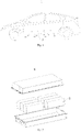
Fig. 1 shows a structural schematic view of a vehicle according to the embodiments of the present application; -
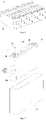
Fig. 2 shows an exploded structural schematic view of a battery pack according to an embodiment of the present application; -
Fig. 3 shows a partial structural schematic view of a battery module set according to an embodiment of the present application; -
Fig. 4 shows an exploded structural schematic view of a secondary battery according to an embodiment of the present application; -
Fig. 5 shows a partial exploded structural schematic view of an end cover assembly according to an embodiment of the present application; -
Fig. 6 shows an enlarged view of a portion A inFig. 5 ; -
Fig. 7 is a structural schematic top view of the end cover assembly of the embodiment shown inFig. 5 in an assembling state; -
Fig. 8 shows a cross-sectional structural schematic view at a line B-B inFig. 7 ; -
Fig. 9 shows a cross-sectional structural schematic view at a line C-C inFig. 7 ; -
Fig. 10 shows an enlarged view of a portion D inFig. 8 ; -
Fig. 11 shows a partial exploded structural schematic view of an end cover assembly according to another embodiment of the present application; -
Fig. 12 shows an enlarged view of a portion E inFig. 11 ; -
Fig. 13 is a structural schematic top view of the end cover assembly of the embodiment shown inFig. 11 in an assembling state; -
Fig. 14 shows a cross-sectional structural schematic view at a line F-F inFig. 13 ; -
Fig. 15 shows an enlarged view of a portion G inFig. 14 . - In the drawings, the drawings are not drawn to the actual scale.
- Reference signs:
- 1 vehicle;
- 10 battery pack;
- 20 battery module set;
- 30 secondary battery; 31 shell; 32 electrode assembly; 321 main body; 321a end face; 322 tab;
- 40 end cover assembly;
- 50 end cover; 50a through hole; 50b concave slot; 50c electrode lead-out hole; 51 connecting portion; 511 snapping slot; 511a position-limiting wall; 52 body portion;
- 60 sealing assembly; 61 position-limiting member; 611 pressing-against portion; 612 position-limiting portion; 613 supporting portion; 614 accommodating slot; 62 sealing member;
- 70 locking-fixing member; 71 opening; 72 accommodating space;
- 80 electrode terminal;
- 90 adapter component;
- X axial direction; Y peripheral direction.
- The implementation of the present application will be described in further detail below in conjunction with the drawings and embodiments. The detailed description and drawings of the embodiments below are used to exemplarily illustrate the principle of the present application, but cannot be used to limit the scope of the present application, that is, the present application can be not limited to the described embodiments.
- In the description of the present application, it should be noted that, unless otherwise specified, "plurality" means more than two; the terms "upper", "lower", "left", "right", "inner", "outer", etc. indicate the orientation or positional relationship only for the convenience of describing the present application and simplifying the description, rather than indicating or implying that the device or the element referred to must have a specific orientation, be configured and operated in a specific orientation, and therefore cannot be understood as a limitation of the present application. In addition, the terms "first", "second", "third", etc. are only used for descriptive purposes, and cannot be understood as indicating or implying relative importance. The term "perpendicular" does not mean strictly perpendicular, but within the allowable range of error. The term "parallel" does not mean strictly parallel, but within the allowable range of error.
- The orientation words appearing in the following description are all directions shown in the drawings, and do not limit the specific structure of the present application. In the description of the present application, it should also be noted that, unless otherwise clearly specified and limited, the terms "mount", "communicate" and "connect" should be understood in a broad sense, for example, it can be a fixed connection, a detachable connection, or an integral connection, it can be a direct connection, or it can be connected indirectly through an intermedium. For those of ordinary skill in the art, the specific meaning of the above-mentioned terms in the present application can be understood according to specific situations.
- In order to better understand the present application, the embodiments of the present application will be described below in conjunction with
Fig. 1 to Fig. 15 . - The embodiment of the present application provides a device using a
secondary battery 30 as a power source. The device can be, but is not limited to, a vehicle, a ship, an aircraft or the like. As shown inFig. 1 , the embodiment of the present application provides thevehicle 1 including a vehicle main body and a battery module. The battery module is arranged in the vehicle main body. Herein, thevehicle 1 may be a pure electric vehicle, a hybrid electric vehicle or an extended-range vehicle. The vehicle main body is provided with a driving motor electrically connected to the battery module. The battery module can supply electrical power to the driving motor. The driving motor is connected to wheels in the vehicle main body through a transmission mechanism to drive the vehicle to travel forward. Optionally, the battery module may be horizontally arranged at a bottom of the vehicle main body. - As shown in
Fig. 2 , the battery module may be abattery pack 10. There are many ways to arrange thebattery pack 10. In some optionally embodiments, thebattery pack 10 includes a housing and the battery module set 20 arranged in the housing. The number of battery module set 20 is one or more. One or more battery module sets 20 are arranged in the housing in array. The type of housing is not limited. The housing can be a frame-shaped housing, a disk-shaped housing, a box-shaped housing or the like. Optionally, the housing includes a lower housing for accommodating the battery module set 20 and an upper housing covered with the lower housing. The upper housing and the lower housing are covered and closed with each other to form an accommodating portion for receiving the battery module set 20. In another optional embodiment, thebattery pack 10 includes the housing and a plurality ofsecondary batteries 30 directly arranged in the housing. - As shown in
Fig. 3 , the battery module may also be the battery module set 20, and the plurality of battery module sets 20 are arranged in the housing and mounted on the vehicle main body. - As shown in
Fig. 3 , the battery module set 20 includes the plurality ofsecondary batteries 30. There are many ways to arrange the battery module set 20. In an embodiment, the battery module set 20 includes the accommodating portion and the plurality ofsecondary batteries 30 located in the accommodating portion. The plurality ofsecondary batteries 30 are arranged side by side in the accommodating portion. There are many ways to arrange the accommodating portion, for example, the accommodating portion includes a shell and a cover plate arranged at the shell; or the accommodating portion includes side plates and end plates that are successively connected with one another to enclose; or the accommodating portion includes end plates arranged opposite each other and a band around the outside of thesecondary battery 30 and the end plates. - After noticing the problem that the operation life of the
secondary battery 30 is short and thesecondary battery 30 cannot be reused, the applicant has conducted the research and the analysis on the various structures of thesecondary battery 30. The applicant found that there is irreversible reaction consumption of electrolyte of thesecondary battery 30, resulting in a decrease in a using capacity of thesecondary battery 30. At the same time, if the electrolyte can be replenished, the degree of the reduction of the capacity of thesecondary battery 30 will be effectively slowed down. However, since the factors such as the safety, the sealing and the like need to be considered in an existing structural design of thesecondary battery 30, the assembled secondary battery 30cannot be refilled with the electrolyte. - Based on the above-mentioned problems discovered by the inventors, the inventors has improved the structure of the
secondary battery 30, and the embodiments of the present application will be further described below. - As shown in
Fig. 4 , thesecondary battery 30 in the embodiments of the present application includes ashell 31 and anelectrode assembly 32 arranged in theshell 31. Theshell 31 in the embodiments of the present application has a cuboid structure or other shapes. Theshell 31 has an internal space for receiving theelectrode assembly 32 and the electrolyte, and an opening communicating with the internal space. Theshell 31 may be made of materials such as aluminum, aluminum alloy, plastic or the like. Theelectrode assembly 32 in the embodiments of the present application can be formed by stacking or winding a first electrode sheet, a second electrode sheet and a separator located between the first electrode sheet and the second electrode sheet and serving as an insulator between the first electrode sheet and the second electrode sheet. In this embodiment, exemplarily, the first electrode sheet is the positive electrode sheet, and the second electrode sheet is the negative electrode sheet. Each of the positive electrode sheet and the negative electrode sheet includes a coated region and an uncoated region. A positive electrode sheet active material coats the coated region of the positive electrode sheet, and a negative electrode sheet active material coats the coated region of the negative electrode sheet. On the coated region, the active material coats a current collector formed by a thin-plate metal foil, and the active material does not coat the uncoated region. After being wound or stacked, theelectrode assembly 32 includes twotabs 322 which are a positive tab and a negative tab respectively. The coated region of the positive electrode sheet and the coated region of the negative electrode sheet form amain body 321. The uncoated regions of the positive electrode sheets are stacked to form the positive tab, and the uncoated regions of the negative electrode sheets are stacked to form the negative tab. In the embodiments of the present application, themain body 321 has twoend faces 321a arranged to be opposite to each other in a length direction, and the positive electrode tab and the negative electrode tab respectively extend beyond the two opposite end faces 321a of themain body 321 in the length direction. - As shown in
Fig. 4 , thesecondary battery 30 in the embodiments of the present application further includes anend cover assembly 40 sealingly connected to theshell 31. Theend cover assembly 40 includes anend cover 50,electrode terminal 80, anadapter component 90, sealingassembly 60 and a locking-fixingmember 70. Theelectrode terminal 80 is arranged on theend cover 50. Theelectrode terminal 80 is electrically connected to thetab 322 of theelectrode assembly 32 through theadapter component 90. The shape of theelectrode terminal 80 may be square or circle, which is not limited here. - As shown in
Fig. 5 and Fig. 6 , theend cover 50 in the embodiments of the present application is provided with an electrode lead-outhole 50c. The electrode lead-outhole 50c penetrates theend cover 50. Theelectrode terminal 80 is arranged on theend cover 50 and covers the electrode lead-outhole 50c. Theend cover 50 is also provided with a throughhole 50a for injecting electrolyte. The throughhole 50a and the electrode lead-outhole 50c are arranged to be spaced apart from each other. Theend cover 50 has a connectingportion 51. The sealingassembly 60 is configured to seal the throughhole 50a on theend cover 50. The locking-fixingmember 70 is configured to be movable relative to the connectingportion 51 of theend cover 50 in a radial direction of the throughhole 50a, so as to switch between a locked state and an unlocked state of the locking-fixingmember 70 and the connectingportion 51. The radial direction of the throughhole 50a refers to a direction perpendicular to an axial direction X of the throughhole 50a. When the locking-fixingmember 70 and the connectingportion 51 are in the locked state, the locking-fixingmember 70 presses against the sealingassembly 60 to restrict the end cover 50 from being separated from the sealingassembly 60. When the locking-fixingmember 70 and the connectingportion 51 are in the unlocked state, theend cover 50 and the sealingassembly 60 are separable to allow the electrolyte to be injected from the throughhole 50a. - In the
secondary battery 30 in the embodiments of the present application, a predetermined amount of electrolyte can be injected into thesecondary battery 30 through the throughhole 50a, then the sealingassembly 60 can seal the throughhole 50a, and finally the locking-fixingmember 70 can lock the connectingportion 51 of theend cover 50. After thesecondary battery 30 is used for a predetermined period of time, the locking-fixingmember 70 unlocks the connectingportion 51 of theend cover 50, and then the sealingassembly 60 is removed to open the throughhole 50a. The predetermined amount of electrolyte can be replenished into thesecondary battery 30 through the throughhole 50a. After completing the electrolyte replenishment process, the sealingassembly 60 seals the throughhole 50a, and the locking-fixingmember 70 locks the connectingportion 51 of theend cover 50 again, and thesecondary battery 30 can continue to be used normally. Thus, thesecondary battery 30 in the embodiments of the present application can be re-filled with the electrolyte after assembled, which can effectively prolong the operation life of thesecondary battery 30. - In an embodiment, as shown in
Fig. 6 , the locking-fixingmember 70 has anopening 71 and anaccommodating space 72 communicating with each other. The connectingportion 51 is configured to enter theaccommodating space 72 through theopening 71. When the locking-fixingmember 70 moves in the radial direction of the throughhole 50a, the connectingportion 51 enters theaccommodating space 72 through theopening 71. After the connectingportion 51 enters theaccommodating space 72, the locking-fixingmember 70 locks the connectingportion 51. When the locking-fixingmember 70 moves in the radial direction of the throughhole 50a, the connectingportion 51 can move out of theaccommodating space 72 through theopening 71, so that the locking-fixingmember 70 and the connectingportion 51 can be unlocked. In an example, a part of the locking-fixingmember 70 where theopening 71 is formed has the good ability of the elastic deformation. The size of theopening 71 of the locking-fixingmember 70 is smaller than the size of theaccommodating space 72. The size of theopening 71 of the locking-fixingmember 70 is smaller than the size of the connectingportion 51, so that when the connectingportion 51 enters theopening 71 or the connectingportion 51 moves out of theopening 71, the size of theopening 71 will become larger to provide a position to the connectingportion 51, and the connectingportion 51 can pass through theopening 71 smoothly. Apart of the locking-fixingmember 70 where theaccommodating space 72 is formed also has the good ability of the elastic deformation. After the connectingportion 51 enters theaccommodating space 72, the part of the locking-fixingmember 70 where theaccommodating space 72 is formed will return to an original state, so that the locking-fixingmember 70 can lock the connectingportion 51 of theend cover 50 through the part of the locking-fixingmember 70 where theaccommodating space 72 is formed. After the connectingportion 51 enters theaccommodating space 72, the locking-fixingmember 70 is not easy to move in the radial direction of the throughhole 50a, so that the connectingportion 51 is not easily detached from theopening 71. - In an embodiment, as shown in
Fig. 6 , the locking-fixingmember 70 is snap-fitted with the connectingportion 51 of theend cover 50, so that the locking-fixingmember 70 and the connectingportion 51 are in the locked state. The locking-fixingmember 70 is detachably connected to the connectingportion 51 of theend cover 50 by means of the snapping connection, so that the locking-fixingmember 70 and the connectingportion 51 can be quickly locked or unlocked to separate. - In an embodiment, as shown in
Fig. 6 , the connectingportion 51 of theend cover 50 is provided with asnapping slot 511, and at least a part of the locking-fixingmember 70 is located in thesnapping slot 511 to restrict the locking-fixingmember 70 from moving in the axial direction X of the throughhole 50a. During the operation process of thesecondary battery 30, thesecondary battery 30 may vibrate or impact in the axial direction X of the throughhole 50a. Since the locking-fixingmember 70 is restricted by the connectingportion 51, the locking-fixingmember 70 and the connectingportion 51 are less likely to move relatively to each other in the axial direction X of the throughhole 50a, thereby reducing the possibility that the locking-fixingmember 70 and the connectingportion 51 are disconnected or loosen with each other because of the movement of the locking-fixingmember 70 in the axial direction X of the throughhole 50a, and reducing the possibility that the sealing is failed and the electrolyte overflows from the throughhole 50a because of the movement of the sealingassembly 60 in the axial direction X of the throughhole 50a. In an example, the snappingslot 511 has a position-limitingwall 511a for resisting against the locking-fixingmember 70 in the axial direction. A surface of the locking-fixingmember 70 away from theend cover 50 is in contact with the position-limitingwall 511a, and the locking-fixingmember 70 and the position-limitingwall 511a are in a surface-to-surface contact. - In an embodiment, as shown in
Fig. 6 , the sealingassembly 60 includes a position-limitingmember 61 and a sealingmember 62. The sealingmember 62 is arranged between the position-limitingmember 61 and theend cover 50, and seals the throughhole 50a. After the locking-fixingmember 70 is connected to the connectingportion 51, the locking-fixingmember 70 can press against the position-limitingmember 61, so that the limiting-fixingmember 61 exerts a compressive stress on the sealingmember 62, thereby restricting the sealingmember 62 from moving in the axial direction X of the throughhole 50a, so that the sealingmember 62 can seal the throughhole 50a. In an example, referring toFigs. 7 to 9 , a part of the sealingmember 62 extends into the throughhole 50a, and another part of the sealingmember 62 is located outside the throughhole 50a. The part of the sealingmember 62 extending into the throughhole 50a is in an interference fit with the throughhole 50a, and the part located outside the throughhole 50a covers the throughhole 50a, thereby improving the sealing performance of the sealingmember 62. Optionally, the material of the sealingmember 62 may be the rubber or the silicone. In an example, as shown inFig. 6 andFig. 9 , the position-limitingmember 61 includes a pressing-againstportion 611 and a position-limitingportion 612. The pressing-againstportion 611 is connected to the position-limitingportion 612 and covers at least a part of the sealingmember 62. Preferably, the pressing-againstportion 611 covers the entire sealingmember 62. At least part of the position-limitingportion 612 is located at a side of the locking-fixingmember 70 close to theend cover 50. The locking-fixingmember 70 presses against the position-limitingportion 612 to restrict the end cover 50 from being separated from the sealingassembly 60. The locking-fixingmember 70 exerts the compressive stress in the axial direction X of the throughhole 50a to a surface of the position-limitingportion 612 away from the end cover 50 from a side of the position-limitingportion 612 away from theend cover 50, and the pressing-againstportion 611 exerts a compressive stress in the axial direction X of the throughhole 50a to the sealingmember 62, so that the pressing-againstportion 611 presses and fixes the sealingmember 62. - In one embodiment, referring to
Fig. 6 andFig. 9 , theend cover 50 further includes abody portion 52. The connectingportion 51 is a boss protruding from a surface of thebody portion 52. The throughhole 50a penetrates the connectingportion 51 and thebody portion 52. At least part of the sealingmember 62 is located at a side of the connectingportion 51 in the axial direction X of the throughhole 50a. In an example, thebody portion 52 has a rectangular plate-shaped structure. The connectingportion 51 includes a middle column-shaped portion and two columns. The two columns are located at two opposite sides of the middle column-shaped portion, that is, the middle column-shaped portion is located between the two columns. The throughhole 50a penetrates the middle column-shaped portion. The snappingslots 511 are respectively formed in the two columns. Optionally, the two columns are evenly spaced apart from each other in the peripheral direction Y of the throughhole 50a. The locking-fixingmember 70 has an annular structure. The locking-fixingmember 70 is snap-fitted in the snappingslots 511 in the two columns, so as to be in a locked state with the connectingportion 51. When locking or unlocking the locking-fixingmember 70 and the connectingportion 51, an auxiliary tool can be used to expand theopening 71 of the locking-fixingmember 70 in advance, so that the two columns can pass through theopening 71 into theaccommodating space 72 or move out of theaccommodating space 72 smoothly. - In an embodiment, referring to
Figs. 6 and10 , the position-limitingmember 61 further includes a supportingportion 613 and anaccommodating slot 614. The supportingportion 613 is connected to the pressing-againstportion 611 and the position-limitingportion 612. Theaccommodating slot 614 penetrates the supportingportion 613 in the radial direction of the throughhole 50a. In the radial direction of the throughhole 50a, the connectingportion 51 of the end cover 50 passes through theaccommodating slot 614. Theaccommodating slot 614 and the connectingportion 51 of theend cover 50 can be inserted and engaged with each other in the axial direction X of the throughhole 50a. The part of the connectingportion 51 located outside theaccommodating slot 614 is used for locking the locking-fixingmember 70 and is arranged in an offset manner with the position-limitingportion 612 of the position-limitingmember 61 in the peripheral direction Y of the throughhole 50a. The position-limitingwall 511a of the snappingslot 511 is arranged on the portion of the connectingportion 51 that is located outside theaccommodating slot 614. The position-limitingmember 61 is restricted by the part of the connectingportion 51 located inside theaccommodating slot 614, so that the position-limitingmember 61 cannot rotate relative to the connectingportion 51. - After the electrolyte is injected into the
secondary battery 30 through the throughhole 50a, the sealingmember 62 is placed on the connectingportion 51, and then the position-limitingmember 61 is inserted and engaged with the connectingportion 51 in the axial direction X of the throughhole 50a. Then, the locking-fixingmember 70 is moved in the radial direction of the throughhole 50a and snap-fitted with the snappingslot 511 of the connectingportion 51 to lock the locking-fixingmember 70 and the connectingportion 51. The locking-fixingmember 70 can restrict the position-limitingmember 61 and the sealingmember 62, and restrict the position-limitingmember 61 and the sealingmember 62 to move in the axial direction X of the throughhole 50a. When the electrolyte needs to be replenished into thesecondary battery 30, the locking-fixingmember 70 is first moved in the radial direction of the throughhole 50a and removed from the snappingslot 511 to detach the locking-fixingmember 70 from the connectingportion 51. In this way, the position-limitingmember 61 and the sealingmember 62 are removed in the axial direction X of the throughhole 50a, and the throughhole 50a is exposed. The electrolyte is replenished to thesecondary battery 30 through the throughhole 50a. - In one embodiment, as shown in
Figs. 6 and10 , theend cover 50 has aconcave slot 50b. The throughhole 50a communicates with theconcave slot 50b. At least a part of the sealingmember 62 is accommodated in theconcave slot 50b, so that it is beneficial to reduce the size of theend cover assembly 40 in the axial direction X of the throughhole 50a, and the energy density of thesecondary battery 30 can be increased. Theconcave slot 50b is arranged in the connectingportion 51 in the axial direction X of the throughhole 50a, theconcave slot 50b is arranged corresponding to the middle-shaped column portion. - In an embodiment, referring to
Fig. 11 to Fig. 15 , the same structures between theend cover assembly 40 in this embodiment and theend cover assembly 40 in the embodiment shown inFig. 5 to Fig. 10 will not be repeated here, and the differences will be mainly described. The connectingportion 51 is a column-shaped boss. The snappingslot 511 formed on the connectingportion 51 is anannular snapping slot 511. The locking-fixingmember 70 has the annular structure with anopening 71, so that the locking-fixingmember 70 can be snap-fitted into the snappingslot 511 of the connectingportion 51 at different positions. The throughhole 50a is located outside the connectingportion 51, that is, the throughhole 50a is spaced apart from the connectingportion 51 in the radial direction of the throughhole 50a. The throughhole 50a penetrates thebody portion 52. In an example, two or more throughholes 50a are arranged to be spaced apart from one another evenly around the connectingportion 51. Each of the position-limitingmember 61 and the sealingmember 62 has an annular structure. Each of the position-limitingmember 61 and the sealingmember 62 is used to be sleeved and connected with the connectingportion 51. The portion of the position-limitingmember 61 that is located at the side of the locking-fixingmember 70 close to theend cover 50 forms a position-limitingportion 612, and the pressing-againstportion 611 is located at the outer periphery of the position-limitingportion 612. After the position-limitingmember 61 and the sealingmember 62 are sleeved on the connectingportion 51, the portion of the connectingportion 51 where the snappingslot 511 is arranged passes through the position-limitingmember 61, so that it is convenient for the locking-fixingmember 70 to be snap-fitted and fixed to thesnapping slot 511 at the side of the position-limitingmember 61 away from the sealingmember 62. The locking-fixingmember 70 exerts the compressive stress in the axial direction X of the throughhole 50a to the position-limitingportion 612 from the side of the position-limitingportion 612 away from the sealingmember 62, so that the pressing-againstportion 611 exerts the compressive stress in the axial direction X of the throughhole 50a to the sealingmember 62, thereby compressing and fixing the sealingmember 62. At least a part of the sealingmember 62 is arranged between the pressing-againstportion 611 and theend cover 50, and seals all the throughholes 50a. - In an embodiment, referring to
Fig. 11 andFig. 15 , aconcave slot 50b is formed on thebody portion 52 of theend cover 50. The throughhole 50a communicates with theconcave slot 50b. The connectingportion 51 is arranged at a bottom of theconcave slot 50b. The connectingportion 51 is the column-shaped boss protruding from thebody portion 52. After the sealingmember 62 is sleeved on the connectingportion 51, at least part of the sealingmember 62 is accommodated in theconcave slot 50b. The part of the sealingmember 62 located in theconcave slot 50b can contact with a bottom wall and a side wall of theconcave slot 50b and maintain a sealing-fiting state, so that it is beneficial to improve the reliability and stability of the sealing between the sealingmember 62 and theend cover 50. Preferably, the position-limitingmember 61 and the sealingmember 62 are integrally located in theconcave slot 50b. - After the electrolyte is injected into the
secondary battery 30 through the throughhole 50a, the sealingmember 62 and the position-limitingmember 61 are sequentially sleeved on the connectingportion 51, the locking-fixingmember 70 is moved in the radial direction of the throughhole 50a and snap-fitted with the snappingslot 511 of the connectingportion 51 to lock the locking-fixingmember 70 and the connectingportion 51. The locking-fixingmember 70 can restrict the position-limitingmember 61 and the sealingmember 62, and restrict the position-limitingmember 61 and the sealingmember 62 from moving in the axial direction X of the throughhole 50a. When the electrolyte needs to be replenished to thesecondary battery 30, the locking-fixingmember 70 is first moved in the radial direction of the throughhole 50a and removed from the snappingslot 511 to detach the locking-fixingmember 70 from the connectingportion 51. In this way, the position-limitingmember 61 and the sealingmember 62 are removed in the axial direction X of the throughhole 50a, and the throughhole 50a is exposed. The electrolyte is replenished to thesecondary battery 30 through the throughhole 50a. - The embodiment of the present application further provides a liquid-injection method for the
secondary battery 30, including - providing the
end cover 50 that includes the throughhole 50a and the connectingportion 51, - injecting electrolyte through the through
hole 50a; - providing the sealing
assembly 60; - mounting the sealing
assembly 60 to theend cover 50, in which the sealingassembly 60 covers the throughhole 50a; - providing the locking-fixing
member 70, and moving the locking-fixingmember 70 toward a direction close to the connectingportion 51 in the radial direction of the throughhole 50a, so that the locking-fixingmember 70 locks the connectingportion 51 to restrict the end cover 50 from being separated from the sealingassembly 60, and the sealingassembly 60 maintains in a sealing state. - In an embodiment, when the electrolyte needs to be replenished to the
secondary battery 30, the locking-fixingmember 70 is moved toward a direction away from the connectingportion 51 in the radial direction of the throughhole 50a, so that the locking-fixingmember 70 and the connectingportion 51 are unlocked to separate the locking-fixingmember 70 from theend cover 50, so as to perform corresponding operations on the sealingassembly 60. - In an embodiment, after the locking-fixing
member 70 is moved toward the direction away from the connectingportion 51 in the radial direction of the throughhole 50a, the liquid-injection method further includes: removing the sealingassembly 60 from theend cover 50, so that the throughhole 50a can be opened, and the electrolyte can be replenished into thesecondary battery 30 through the throughhole 50a. After completing the electrolyte replenishment work, the sealingassembly 60 is remounted on theend cover 50 and covers the throughhole 50a. Then the locking-fixingmember 70 locks the connectingportion 51, so that the sealingassembly 60 can maintain in the sealing state. - The embodiment of the present application further provides a liquid-injection device for injecting the electrolyte into the
secondary battery 30, including a liquid injection component and a detaching-and-mounting component of the locking-fixing member. The liquid injection component is configured to inject the electrolyte into the throughhole 50a. The dismounting-and-mounting component of the locking-fixing member is configured to move the locking-fixingmember 70 toward the direction close to the connectingportion 51 in the radial direction of the throughhole 50a in the unlocked state, so that the locking-fixingmember 70 locks the connectingportion 51 to restrict the end cover 50 from being separated from the sealingassembly 60. Or the dismounting-and-mounting component of the locking-fixing member is configured to move the locking-fixingmember 70 toward the direction away from the connectingportion 51 in the radial direction of the throughhole 50a, so that the locking-fixingmember 70 and the connectingportion 51 are unlocked. The dismounting-and-mounting component of the locking-fixing member can move the locking-fixingmember 70 in the radial direction of the throughhole 50a, so that the locking-fixingmember 70 and the connectingportion 51 can be switched between the locked state and the unlocked state. - In an embodiment, the liquid-injection device further includes a dismounting-and-mounting component of the sealing assembly. The dismounting-and-mounting component of the sealing assembly is configured to mount the sealing
assembly 60 on theend cover 50, or dismount the sealingassembly 60 from theend cover 50. - The liquid-injection device in the embodiments of the present application can be used in conjunction with the
end cover assembly 40 in the above embodiment, thereby improving the automation control degree of an electrolyte replenishing process of thesecondary battery 30, reducing the manual labor intensity, and improving the working efficiency of the electrolyte replenishing process. - Although the present application has been described with reference to the preferred embodiments, various modifications can be made to the present application and the components in the present application can be replaced with equivalents without departing from the scope of the present application. In particular, as long as there is no structural conflict, various technical features mentioned in the various embodiments can be combined in any way. The present application is not limited to the specific embodiments disclosed in the text, but includes all technical solutions falling within the scope of claims.
Claims (20)
- An end cover assembly for a secondary battery, comprisingan end cover, provided with a through hole for injecting electrolyte therethrough and comprising a connecting portion;a sealing assembly, configured to seal the through hole;a locking-fixing member, configured to be movable relative to the connecting portion in a radial direction of the through hole, so as to realize switching between a locked state and an unlocked state of the locking-fixing member and the connecting portion, wherein in the locked state, the locking-fixing member presses against the sealing assembly to restrict the end cover from being separated from the sealing assembly; in the unlocked state, the end cover and the sealing assembly are separable to allow the electrolyte to be injected from the through hole.
- The end cover assembly according to claim 1, wherein the locking-fixing member comprises an opening and an accommodating space communicating with each other, and the connecting portion is configured to enter the accommodating space through the opening, or the connecting portion is configured to be separated from the accommodating space through the opening.
- The end cover assembly according to claim 1 or 2, wherein the locking-fixing member is snap-fitted with the connecting portion, so that the locking-fixing member and the connecting portion are in the locked state.
- The end cover assembly according to claim 3, wherein the connecting portion is provided with a snapping slot, and at least part of the locking-fixing member is located in the snapping slot to restrict the locking-fixing member from moving in an axial direction of the through hole.
- The end cover assembly according to claim 4, wherein the snapping slot comprises a position-limiting wall configured to resist against the locking-fixing member in the axial direction.
- The end cover assembly according to any one of claims 3-5, wherein the sealing assembly comprises a position-limiting member and a sealing member, the sealing member seals the through hole, and the sealing member is arranged between the position-limiting member and the end cover.
- The end cover assembly according to claim 6, wherein the position-limiting member comprises a pressing-against portion and a position-limiting portion, the pressing-against portion is connected to the position-limiting portion and covers at least a part of the sealing member, and the locking-fixing member presses against the position-limiting portion to restrict the end cover from being separated from the sealing assembly.
- The end cover assembly according to claim 7, wherein the end cover further comprises a body portion, and the connecting portion is a boss protruding from a surface of the body portion.
- The end cover assembly according to claim 8, wherein the through hole is located outside the connecting portion and penetrates the body portion in its own axial direction; each of the position-limiting member and the sealing member has an annular structure and is sleeved and connected to the connecting portion.
- The end cover assembly according to claim 8, wherein the through hole penetrates the connecting portion and the body portion in its own axial direction, and at least part of the sealing member is located at a side of the connecting portion in the axial direction.
- The end cover assembly according to claim 10, wherein the position-limiting member further comprises an accommodating slot and a supporting portion connecting to the pressing-against portion and the position-limiting portion, and the accommodating slot penetrates the supporting portion in the radial direction;
the connecting portion passes through the accommodating slot, and a portion of the connecting portion located outside the accommodating slot is misaligned with the position-limiting portion in a peripheral direction of the through hole, and is configured to be locked with the locking-fixing member. - The end cover assembly according to any one of claims 6-11, wherein the end cover comprises a concave slot, the through hole is communicated with the concave slot, and at least part of the sealing member is accommodated in the concave slot.
- A secondary battery, comprising the end cover assembly according to any one of claims 1-12.
- A battery module, comprising the secondary battery according to claim 13.
- An apparatus comprising the secondary battery according to claim 13, the secondary battery being configured to supply electrical power.
- A liquid-injection method for a secondary battery, comprisingproviding an end cover that comprises a through hole and a connecting portion,injecting electrolyte through the through hole;providing a sealing assembly;mounting the sealing assembly to the end cover;providing a locking-fixing member, and moving the locking-fixing member toward a direction close to the connecting portion in a radial direction of the through hole, so that the locking-fixing member locks the connecting portion to restrict the end cover from being separated from the sealing assembly.
- The liquid-injection method according to claim 16, further comprising
moving the locking-fixing member toward a direction away from the connecting portion in the radial direction of the through hole, so as to unlock the locking-fixing member and the connecting portion, and separate the locking-fixing member from the end cover. - The liquid-injection method according to claim 17, after the moving the locking-fixing member in the direction away from the connecting portion in the radial direction of the through hole, the method further comprising
removing the sealing assembly from the end cover. - A liquid-injection device, for injecting the electrolyte into the secondary battery according to claim 13, comprisinga liquid injection component, configured to inject the electrolyte into the through hole; anda dismounting-and-mounting component of the locking-fixing member, configured to move the locking-fixing member toward a direction close to the connecting portion in the radial direction of the through hole in the unlocked state, so that the locking-fixing member locks the connecting portion to restrict the end cover from being separated from the sealing assembly; or configured to move the locking-fixing member toward a direction away from the connecting portion in the radial direction of the through hole, so that the locking-fixing member and the connecting portion are unlocked.
- The liquid-injection device according to claim 19, further comprising
a dismounting-and-mounting component of the sealing assembly, configured to mount the sealing assembly on the end cover, or dismount the sealing assembly from the end cover.
Priority Applications (1)
| Application Number | Priority Date | Filing Date | Title |
|---|---|---|---|
| HUE20936418A HUE068271T2 (en) | 2020-05-19 | 2020-05-19 | End cover assembly, liquid injection method and device |
Applications Claiming Priority (1)
| Application Number | Priority Date | Filing Date | Title |
|---|---|---|---|
| PCT/CN2020/091108 WO2021232252A1 (en) | 2020-05-19 | 2020-05-19 | End cover assembly, secondary battery, battery module, device, liquid injection method and device |
Publications (4)
| Publication Number | Publication Date |
|---|---|
| EP4053991A1 true EP4053991A1 (en) | 2022-09-07 |
| EP4053991A4 EP4053991A4 (en) | 2023-01-11 |
| EP4053991C0 EP4053991C0 (en) | 2024-07-03 |
| EP4053991B1 EP4053991B1 (en) | 2024-07-03 |
Family
ID=78709012
Family Applications (1)
| Application Number | Title | Priority Date | Filing Date |
|---|---|---|---|
| EP20936418.1A Active EP4053991B1 (en) | 2020-05-19 | 2020-05-19 | End cover assembly, liquid injection method and device |
Country Status (5)
| Country | Link |
|---|---|
| US (2) | US11777184B2 (en) |
| EP (1) | EP4053991B1 (en) |
| CN (1) | CN114365346B (en) |
| HU (1) | HUE068271T2 (en) |
| WO (1) | WO2021232252A1 (en) |
Families Citing this family (4)
| Publication number | Priority date | Publication date | Assignee | Title |
|---|---|---|---|---|
| JP7581372B2 (en) * | 2021-04-02 | 2024-11-12 | 香港時代新能源科技有限公司 | End cap assembly, battery cell, battery and battery cell manufacturing method and apparatus |
| CN217334362U (en) * | 2022-06-20 | 2022-08-30 | 宁德时代新能源科技股份有限公司 | End cover, end cover assembly, battery monomer, battery and power consumption device |
| CN115117578B (en) * | 2022-07-29 | 2023-09-08 | 厦门海辰储能科技股份有限公司 | Sealing nail and application thereof, sealing assembly and application and sealing method thereof |
| CN118040266A (en) * | 2024-04-15 | 2024-05-14 | 宁德时代新能源科技股份有限公司 | Liquid injection equipment, battery production line and liquid injection method |
Family Cites Families (21)
| Publication number | Priority date | Publication date | Assignee | Title |
|---|---|---|---|---|
| US2240314A (en) * | 1940-04-09 | 1941-04-29 | American Hard Rubber Co | Closure for battery box covers |
| US5993991A (en) * | 1996-01-29 | 1999-11-30 | Jones; William E. M. | Battery vent plug improvement |
| JP2007257942A (en) * | 2006-03-22 | 2007-10-04 | Sanyo Electric Co Ltd | Nonaqueous secondary battery |
| JP5135715B2 (en) * | 2006-05-31 | 2013-02-06 | トヨタ自動車株式会社 | Sealed battery and method for manufacturing the same |
| CN202042559U (en) * | 2011-03-30 | 2011-11-16 | 比亚迪股份有限公司 | A lithium ion battery |
| CN202495487U (en) * | 2012-02-13 | 2012-10-17 | 东莞新能源科技有限公司 | A power battery and its top cover |
| CN202585544U (en) | 2012-03-06 | 2012-12-05 | 宁德新能源科技有限公司 | Power battery and top cover thereof |
| JP2014099266A (en) * | 2012-11-13 | 2014-05-29 | Toyota Industries Corp | Power storage device and sealing method of power storage device |
| JP2015050114A (en) * | 2013-09-03 | 2015-03-16 | 株式会社Gsユアサ | Plug for storage battery and storage battery |
| JP2015082495A (en) * | 2013-10-24 | 2015-04-27 | 株式会社豊田自動織機 | Temporary sealing plug for power storage device |
| JP2016162550A (en) * | 2015-02-27 | 2016-09-05 | 株式会社豊田自動織機 | Sealing device |
| CN205069696U (en) | 2015-10-19 | 2016-03-02 | 宁德时代新能源科技有限公司 | Secondary cell's subassembly for top cap |
| CN205881986U (en) * | 2016-08-12 | 2017-01-11 | 苏州三众新能源科技有限公司 | A apron for lithium battery shell body |
| CN206992160U (en) * | 2017-05-04 | 2018-02-09 | 湖州百成新型电池有限公司 | Battery cover plate structure |
| CN207116574U (en) * | 2017-06-06 | 2018-03-16 | 深圳市陶金科技有限公司 | A kind of fluid injection seal assembly, power battery cover board component and electrokinetic cell |
| JP2019029209A (en) * | 2017-07-31 | 2019-02-21 | 株式会社Gsユアサ | Power storage element |
| KR102198047B1 (en) * | 2017-11-01 | 2021-01-04 | 삼성에스디아이 주식회사 | Rechargeable battery |
| CN207818752U (en) * | 2017-12-19 | 2018-09-04 | 比亚迪股份有限公司 | Liquid injection hole sealing device, cover assembly, battery, battery module and automobile |
| CN208819960U (en) * | 2018-06-29 | 2019-05-03 | 湖北美赛尔科技有限公司 | A kind of lithium ion battery |
| CN209515756U (en) * | 2019-01-24 | 2019-10-18 | 合肥国轩高科动力能源有限公司 | Lithium battery cover plate and lithium battery case |
| CN209843759U (en) * | 2019-07-16 | 2019-12-24 | 珠海格力电器股份有限公司 | Battery cover plate assembly and battery |
-
2020
- 2020-05-19 HU HUE20936418A patent/HUE068271T2/en unknown
- 2020-05-19 EP EP20936418.1A patent/EP4053991B1/en active Active
- 2020-05-19 WO PCT/CN2020/091108 patent/WO2021232252A1/en not_active Ceased
- 2020-05-19 CN CN202080063127.1A patent/CN114365346B/en active Active
-
2022
- 2022-06-03 US US17/831,673 patent/US11777184B2/en active Active
-
2023
- 2023-08-16 US US18/234,496 patent/US12100867B2/en active Active
Also Published As
| Publication number | Publication date |
|---|---|
| CN114365346A (en) | 2022-04-15 |
| EP4053991A4 (en) | 2023-01-11 |
| WO2021232252A1 (en) | 2021-11-25 |
| EP4053991C0 (en) | 2024-07-03 |
| EP4053991B1 (en) | 2024-07-03 |
| US11777184B2 (en) | 2023-10-03 |
| HUE068271T2 (en) | 2024-12-28 |
| US12100867B2 (en) | 2024-09-24 |
| US20220294093A1 (en) | 2022-09-15 |
| US20230395958A1 (en) | 2023-12-07 |
| CN114365346B (en) | 2023-02-28 |
Similar Documents
| Publication | Publication Date | Title |
|---|---|---|
| US11777184B2 (en) | End cover assembly, secondary battery, battery module, apparatus, liquid-injection method and device | |
| EP4044329B1 (en) | Battery box body, battery, electric device, and method and device for manufacturing box body | |
| EP1744383B1 (en) | Electrical device with film covering and frame member | |
| EP4456294A1 (en) | Battery, electric device, and forming method for battery | |
| US12537249B2 (en) | End cover assembly, battery cell, battery pack, apparatus and liquid-injection method | |
| CN212625812U (en) | End cap assembly, battery cell, battery and electrical device | |
| US8147997B2 (en) | Film-covered electrical device packaging system | |
| CN116325341B (en) | Battery, power utilization device, method and apparatus for preparing battery | |
| US20240304959A1 (en) | End cover assembly, battery cell, battery, and electric device | |
| CN212161871U (en) | End cap assemblies, secondary batteries, battery modules, devices, and liquid injection devices | |
| EP3614452A1 (en) | Battery module | |
| US20240266657A1 (en) | Box body for battery, battery, power consumption apparatus, and method and apparatus for preparing battery | |
| EP4675816A1 (en) | Battery and electric device | |
| JP7621371B6 (en) | Battery, electrical equipment, battery manufacturing method and manufacturing device | |
| CN219436048U (en) | Box, battery and power consumption device | |
| US12224456B2 (en) | Connection component, battery cell, battery and electrical device | |
| JP7746549B2 (en) | Battery cell, battery, power consumption device, and battery cell manufacturing method and apparatus | |
| CN118104032A (en) | Battery cells, batteries and electrical equipment | |
| CN116742217A (en) | Battery cell, battery, power utilization device, manufacturing method and manufacturing system | |
| US20250391968A1 (en) | Battery cell, battery and electrical apparatus | |
| CN223598941U (en) | Pressure release mechanism, battery and power utilization device | |
| EP4235928B1 (en) | Battery, manufacturing method therefor, manufacturing device thereof, and electrical apparatus | |
| CN222365602U (en) | Composite pole piece, battery cell, battery, electrical equipment, rolling device and battery manufacturing equipment | |
| CN220710582U (en) | Acquisition device, battery and power utilization device | |
| US20250070332A1 (en) | Battery cell, battery, and electrical device |
Legal Events
| Date | Code | Title | Description |
|---|---|---|---|
| STAA | Information on the status of an ep patent application or granted ep patent |
Free format text: STATUS: THE INTERNATIONAL PUBLICATION HAS BEEN MADE |
|
| PUAI | Public reference made under article 153(3) epc to a published international application that has entered the european phase |
Free format text: ORIGINAL CODE: 0009012 |
|
| STAA | Information on the status of an ep patent application or granted ep patent |
Free format text: STATUS: REQUEST FOR EXAMINATION WAS MADE |
|
| 17P | Request for examination filed |
Effective date: 20220531 |
|
| AK | Designated contracting states |
Kind code of ref document: A1 Designated state(s): AL AT BE BG CH CY CZ DE DK EE ES FI FR GB GR HR HU IE IS IT LI LT LU LV MC MK MT NL NO PL PT RO RS SE SI SK SM TR |
|
| A4 | Supplementary search report drawn up and despatched |
Effective date: 20221208 |
|
| RIC1 | Information provided on ipc code assigned before grant |
Ipc: H01M 50/636 20210101ALI20221202BHEP Ipc: H01M 50/645 20210101ALI20221202BHEP Ipc: H01M 50/15 20210101ALI20221202BHEP Ipc: H01M 50/60 20210101AFI20221202BHEP |
|
| STAA | Information on the status of an ep patent application or granted ep patent |
Free format text: STATUS: EXAMINATION IS IN PROGRESS |
|
| 17Q | First examination report despatched |
Effective date: 20230601 |
|
| DAV | Request for validation of the european patent (deleted) | ||
| DAX | Request for extension of the european patent (deleted) | ||
| GRAP | Despatch of communication of intention to grant a patent |
Free format text: ORIGINAL CODE: EPIDOSNIGR1 |
|
| STAA | Information on the status of an ep patent application or granted ep patent |
Free format text: STATUS: GRANT OF PATENT IS INTENDED |
|
| RIC1 | Information provided on ipc code assigned before grant |
Ipc: H01M 50/186 20210101ALI20240408BHEP Ipc: H01M 50/148 20210101ALI20240408BHEP Ipc: H01M 50/636 20210101ALI20240408BHEP Ipc: H01M 50/645 20210101ALI20240408BHEP Ipc: H01M 50/15 20210101ALI20240408BHEP Ipc: H01M 50/60 20210101AFI20240408BHEP |
|
| GRAS | Grant fee paid |
Free format text: ORIGINAL CODE: EPIDOSNIGR3 |
|
| INTG | Intention to grant announced |
Effective date: 20240423 |
|
| GRAA | (expected) grant |
Free format text: ORIGINAL CODE: 0009210 |
|
| STAA | Information on the status of an ep patent application or granted ep patent |
Free format text: STATUS: THE PATENT HAS BEEN GRANTED |
|
| AK | Designated contracting states |
Kind code of ref document: B1 Designated state(s): AL AT BE BG CH CY CZ DE DK EE ES FI FR GB GR HR HU IE IS IT LI LT LU LV MC MK MT NL NO PL PT RO RS SE SI SK SM TR |
|
| REG | Reference to a national code |
Ref country code: CH Ref legal event code: EP |
|
| REG | Reference to a national code |
Ref country code: DE Ref legal event code: R096 Ref document number: 602020033575 Country of ref document: DE |
|
| U01 | Request for unitary effect filed |
Effective date: 20240726 |
|
| U07 | Unitary effect registered |
Designated state(s): AT BE BG DE DK EE FI FR IT LT LU LV MT NL PT SE SI Effective date: 20240812 |
|
| REG | Reference to a national code |
Ref country code: GB Ref legal event code: 732E Free format text: REGISTERED BETWEEN 20240829 AND 20240904 |
|
| RAP2 | Party data changed (patent owner data changed or rights of a patent transferred) |
Owner name: CONTEMPORARY AMPEREX TECHNOLOGY(HONG KONG) LIMITED |
|
| U1K | Transfer of rights of the unitary patent after the registration of the unitary effect |
Owner name: CONTEMPORARY AMPEREX TECHNOLOGY(HONG KONG) LIMITED; HK |
|
| REG | Reference to a national code |
Ref country code: HU Ref legal event code: AG4A Ref document number: E068271 Country of ref document: HU |
|
| PG25 | Lapsed in a contracting state [announced via postgrant information from national office to epo] |
Ref country code: NO Free format text: LAPSE BECAUSE OF FAILURE TO SUBMIT A TRANSLATION OF THE DESCRIPTION OR TO PAY THE FEE WITHIN THE PRESCRIBED TIME-LIMIT Effective date: 20241003 |
|
| PG25 | Lapsed in a contracting state [announced via postgrant information from national office to epo] |
Ref country code: PL Free format text: LAPSE BECAUSE OF FAILURE TO SUBMIT A TRANSLATION OF THE DESCRIPTION OR TO PAY THE FEE WITHIN THE PRESCRIBED TIME-LIMIT Effective date: 20240703 Ref country code: GR Free format text: LAPSE BECAUSE OF FAILURE TO SUBMIT A TRANSLATION OF THE DESCRIPTION OR TO PAY THE FEE WITHIN THE PRESCRIBED TIME-LIMIT Effective date: 20241004 |
|
| PG25 | Lapsed in a contracting state [announced via postgrant information from national office to epo] |
Ref country code: IS Free format text: LAPSE BECAUSE OF FAILURE TO SUBMIT A TRANSLATION OF THE DESCRIPTION OR TO PAY THE FEE WITHIN THE PRESCRIBED TIME-LIMIT Effective date: 20241103 |
|
| PG25 | Lapsed in a contracting state [announced via postgrant information from national office to epo] |
Ref country code: HR Free format text: LAPSE BECAUSE OF FAILURE TO SUBMIT A TRANSLATION OF THE DESCRIPTION OR TO PAY THE FEE WITHIN THE PRESCRIBED TIME-LIMIT Effective date: 20240703 Ref country code: CZ Free format text: LAPSE BECAUSE OF FAILURE TO SUBMIT A TRANSLATION OF THE DESCRIPTION OR TO PAY THE FEE WITHIN THE PRESCRIBED TIME-LIMIT Effective date: 20240703 |
|
| PG25 | Lapsed in a contracting state [announced via postgrant information from national office to epo] |
Ref country code: ES Free format text: LAPSE BECAUSE OF FAILURE TO SUBMIT A TRANSLATION OF THE DESCRIPTION OR TO PAY THE FEE WITHIN THE PRESCRIBED TIME-LIMIT Effective date: 20240703 Ref country code: RS Free format text: LAPSE BECAUSE OF FAILURE TO SUBMIT A TRANSLATION OF THE DESCRIPTION OR TO PAY THE FEE WITHIN THE PRESCRIBED TIME-LIMIT Effective date: 20241003 |
|
| PG25 | Lapsed in a contracting state [announced via postgrant information from national office to epo] |
Ref country code: RS Free format text: LAPSE BECAUSE OF FAILURE TO SUBMIT A TRANSLATION OF THE DESCRIPTION OR TO PAY THE FEE WITHIN THE PRESCRIBED TIME-LIMIT Effective date: 20241003 Ref country code: PL Free format text: LAPSE BECAUSE OF FAILURE TO SUBMIT A TRANSLATION OF THE DESCRIPTION OR TO PAY THE FEE WITHIN THE PRESCRIBED TIME-LIMIT Effective date: 20240703 Ref country code: NO Free format text: LAPSE BECAUSE OF FAILURE TO SUBMIT A TRANSLATION OF THE DESCRIPTION OR TO PAY THE FEE WITHIN THE PRESCRIBED TIME-LIMIT Effective date: 20241003 Ref country code: IS Free format text: LAPSE BECAUSE OF FAILURE TO SUBMIT A TRANSLATION OF THE DESCRIPTION OR TO PAY THE FEE WITHIN THE PRESCRIBED TIME-LIMIT Effective date: 20241103 Ref country code: HR Free format text: LAPSE BECAUSE OF FAILURE TO SUBMIT A TRANSLATION OF THE DESCRIPTION OR TO PAY THE FEE WITHIN THE PRESCRIBED TIME-LIMIT Effective date: 20240703 Ref country code: GR Free format text: LAPSE BECAUSE OF FAILURE TO SUBMIT A TRANSLATION OF THE DESCRIPTION OR TO PAY THE FEE WITHIN THE PRESCRIBED TIME-LIMIT Effective date: 20241004 Ref country code: ES Free format text: LAPSE BECAUSE OF FAILURE TO SUBMIT A TRANSLATION OF THE DESCRIPTION OR TO PAY THE FEE WITHIN THE PRESCRIBED TIME-LIMIT Effective date: 20240703 Ref country code: CZ Free format text: LAPSE BECAUSE OF FAILURE TO SUBMIT A TRANSLATION OF THE DESCRIPTION OR TO PAY THE FEE WITHIN THE PRESCRIBED TIME-LIMIT Effective date: 20240703 |
|
| PG25 | Lapsed in a contracting state [announced via postgrant information from national office to epo] |
Ref country code: SM Free format text: LAPSE BECAUSE OF FAILURE TO SUBMIT A TRANSLATION OF THE DESCRIPTION OR TO PAY THE FEE WITHIN THE PRESCRIBED TIME-LIMIT Effective date: 20240703 |
|
| PG25 | Lapsed in a contracting state [announced via postgrant information from national office to epo] |
Ref country code: SK Free format text: LAPSE BECAUSE OF FAILURE TO SUBMIT A TRANSLATION OF THE DESCRIPTION OR TO PAY THE FEE WITHIN THE PRESCRIBED TIME-LIMIT Effective date: 20240703 |
|
| PLBE | No opposition filed within time limit |
Free format text: ORIGINAL CODE: 0009261 |
|
| STAA | Information on the status of an ep patent application or granted ep patent |
Free format text: STATUS: NO OPPOSITION FILED WITHIN TIME LIMIT |
|
| 26N | No opposition filed |
Effective date: 20250404 |
|
| U20 | Renewal fee for the european patent with unitary effect paid |
Year of fee payment: 6 Effective date: 20250522 |
|
| PGFP | Annual fee paid to national office [announced via postgrant information from national office to epo] |
Ref country code: HU Payment date: 20250430 Year of fee payment: 6 |
|
| REG | Reference to a national code |
Ref country code: CH Ref legal event code: H13 Free format text: ST27 STATUS EVENT CODE: U-0-0-H10-H13 (AS PROVIDED BY THE NATIONAL OFFICE) Effective date: 20251223 |
|
| PG25 | Lapsed in a contracting state [announced via postgrant information from national office to epo] |
Ref country code: CH Free format text: LAPSE BECAUSE OF NON-PAYMENT OF DUE FEES Effective date: 20250531 |
|
| PG25 | Lapsed in a contracting state [announced via postgrant information from national office to epo] |
Ref country code: MC Free format text: LAPSE BECAUSE OF FAILURE TO SUBMIT A TRANSLATION OF THE DESCRIPTION OR TO PAY THE FEE WITHIN THE PRESCRIBED TIME-LIMIT Effective date: 20240703 |
|
| PGFP | Annual fee paid to national office [announced via postgrant information from national office to epo] |
Ref country code: GB Payment date: 20260331 Year of fee payment: 7 |
|
| PG25 | Lapsed in a contracting state [announced via postgrant information from national office to epo] |
Ref country code: IE Free format text: LAPSE BECAUSE OF NON-PAYMENT OF DUE FEES Effective date: 20250519 |
|
| PG25 | Lapsed in a contracting state [announced via postgrant information from national office to epo] |
Ref country code: RO Free format text: LAPSE BECAUSE OF FAILURE TO SUBMIT A TRANSLATION OF THE DESCRIPTION OR TO PAY THE FEE WITHIN THE PRESCRIBED TIME-LIMIT Effective date: 20240703 |