EP4053968A1 - Apparatus and method for detecting damage to battery pack case - Google Patents
Apparatus and method for detecting damage to battery pack case Download PDFInfo
- Publication number
- EP4053968A1 EP4053968A1 EP20912750.5A EP20912750A EP4053968A1 EP 4053968 A1 EP4053968 A1 EP 4053968A1 EP 20912750 A EP20912750 A EP 20912750A EP 4053968 A1 EP4053968 A1 EP 4053968A1
- Authority
- EP
- European Patent Office
- Prior art keywords
- voltage
- conductive member
- case
- bms
- battery pack
- Prior art date
- Legal status (The legal status is an assumption and is not a legal conclusion. Google has not performed a legal analysis and makes no representation as to the accuracy of the status listed.)
- Granted
Links
Images


Classifications
-
- H—ELECTRICITY
- H01—ELECTRIC ELEMENTS
- H01M—PROCESSES OR MEANS, e.g. BATTERIES, FOR THE DIRECT CONVERSION OF CHEMICAL ENERGY INTO ELECTRICAL ENERGY
- H01M10/00—Secondary cells; Manufacture thereof
- H01M10/42—Methods or arrangements for servicing or maintenance of secondary cells or secondary half-cells
- H01M10/48—Accumulators combined with arrangements for measuring, testing or indicating the condition of cells, e.g. the level or density of the electrolyte
- H01M10/482—Accumulators combined with arrangements for measuring, testing or indicating the condition of cells, e.g. the level or density of the electrolyte for several batteries or cells simultaneously or sequentially
-
- H—ELECTRICITY
- H01—ELECTRIC ELEMENTS
- H01M—PROCESSES OR MEANS, e.g. BATTERIES, FOR THE DIRECT CONVERSION OF CHEMICAL ENERGY INTO ELECTRICAL ENERGY
- H01M10/00—Secondary cells; Manufacture thereof
- H01M10/42—Methods or arrangements for servicing or maintenance of secondary cells or secondary half-cells
- H01M10/425—Structural combination with electronic components, e.g. electronic circuits integrated to the outside of the casing
-
- H—ELECTRICITY
- H01—ELECTRIC ELEMENTS
- H01M—PROCESSES OR MEANS, e.g. BATTERIES, FOR THE DIRECT CONVERSION OF CHEMICAL ENERGY INTO ELECTRICAL ENERGY
- H01M10/00—Secondary cells; Manufacture thereof
- H01M10/42—Methods or arrangements for servicing or maintenance of secondary cells or secondary half-cells
- H01M10/425—Structural combination with electronic components, e.g. electronic circuits integrated to the outside of the casing
- H01M10/4257—Smart batteries, e.g. electronic circuits inside the housing of the cells or batteries
-
- H—ELECTRICITY
- H01—ELECTRIC ELEMENTS
- H01M—PROCESSES OR MEANS, e.g. BATTERIES, FOR THE DIRECT CONVERSION OF CHEMICAL ENERGY INTO ELECTRICAL ENERGY
- H01M10/00—Secondary cells; Manufacture thereof
- H01M10/42—Methods or arrangements for servicing or maintenance of secondary cells or secondary half-cells
- H01M10/4285—Testing apparatus
-
- H—ELECTRICITY
- H01—ELECTRIC ELEMENTS
- H01M—PROCESSES OR MEANS, e.g. BATTERIES, FOR THE DIRECT CONVERSION OF CHEMICAL ENERGY INTO ELECTRICAL ENERGY
- H01M10/00—Secondary cells; Manufacture thereof
- H01M10/42—Methods or arrangements for servicing or maintenance of secondary cells or secondary half-cells
- H01M10/48—Accumulators combined with arrangements for measuring, testing or indicating the condition of cells, e.g. the level or density of the electrolyte
-
- H—ELECTRICITY
- H01—ELECTRIC ELEMENTS
- H01M—PROCESSES OR MEANS, e.g. BATTERIES, FOR THE DIRECT CONVERSION OF CHEMICAL ENERGY INTO ELECTRICAL ENERGY
- H01M50/00—Constructional details or processes of manufacture of the non-active parts of electrochemical cells other than fuel cells, e.g. hybrid cells
- H01M50/20—Mountings; Secondary casings or frames; Racks, modules or packs; Suspension devices; Shock absorbers; Transport or carrying devices; Holders
- H01M50/204—Racks, modules or packs for multiple batteries or multiple cells
-
- H—ELECTRICITY
- H01—ELECTRIC ELEMENTS
- H01M—PROCESSES OR MEANS, e.g. BATTERIES, FOR THE DIRECT CONVERSION OF CHEMICAL ENERGY INTO ELECTRICAL ENERGY
- H01M50/00—Constructional details or processes of manufacture of the non-active parts of electrochemical cells other than fuel cells, e.g. hybrid cells
- H01M50/20—Mountings; Secondary casings or frames; Racks, modules or packs; Suspension devices; Shock absorbers; Transport or carrying devices; Holders
- H01M50/244—Secondary casings; Racks; Suspension devices; Carrying devices; Holders characterised by their mounting method
-
- H—ELECTRICITY
- H01—ELECTRIC ELEMENTS
- H01M—PROCESSES OR MEANS, e.g. BATTERIES, FOR THE DIRECT CONVERSION OF CHEMICAL ENERGY INTO ELECTRICAL ENERGY
- H01M50/00—Constructional details or processes of manufacture of the non-active parts of electrochemical cells other than fuel cells, e.g. hybrid cells
- H01M50/50—Current conducting connections for cells or batteries
- H01M50/569—Constructional details of current conducting connections for detecting conditions inside cells or batteries, e.g. details of voltage sensing terminals
-
- H—ELECTRICITY
- H01—ELECTRIC ELEMENTS
- H01M—PROCESSES OR MEANS, e.g. BATTERIES, FOR THE DIRECT CONVERSION OF CHEMICAL ENERGY INTO ELECTRICAL ENERGY
- H01M10/00—Secondary cells; Manufacture thereof
- H01M10/42—Methods or arrangements for servicing or maintenance of secondary cells or secondary half-cells
- H01M10/425—Structural combination with electronic components, e.g. electronic circuits integrated to the outside of the casing
- H01M2010/4271—Battery management systems including electronic circuits, e.g. control of current or voltage to keep battery in healthy state, cell balancing
-
- H—ELECTRICITY
- H01—ELECTRIC ELEMENTS
- H01M—PROCESSES OR MEANS, e.g. BATTERIES, FOR THE DIRECT CONVERSION OF CHEMICAL ENERGY INTO ELECTRICAL ENERGY
- H01M2200/00—Safety devices for primary or secondary batteries
-
- H—ELECTRICITY
- H01—ELECTRIC ELEMENTS
- H01M—PROCESSES OR MEANS, e.g. BATTERIES, FOR THE DIRECT CONVERSION OF CHEMICAL ENERGY INTO ELECTRICAL ENERGY
- H01M2220/00—Batteries for particular applications
- H01M2220/10—Batteries in stationary systems, e.g. emergency power source in plant
-
- H—ELECTRICITY
- H01—ELECTRIC ELEMENTS
- H01M—PROCESSES OR MEANS, e.g. BATTERIES, FOR THE DIRECT CONVERSION OF CHEMICAL ENERGY INTO ELECTRICAL ENERGY
- H01M2220/00—Batteries for particular applications
- H01M2220/20—Batteries in motive systems, e.g. vehicle, ship, plane
-
- H—ELECTRICITY
- H01—ELECTRIC ELEMENTS
- H01M—PROCESSES OR MEANS, e.g. BATTERIES, FOR THE DIRECT CONVERSION OF CHEMICAL ENERGY INTO ELECTRICAL ENERGY
- H01M2220/00—Batteries for particular applications
- H01M2220/30—Batteries in portable systems, e.g. mobile phone, laptop
-
- Y—GENERAL TAGGING OF NEW TECHNOLOGICAL DEVELOPMENTS; GENERAL TAGGING OF CROSS-SECTIONAL TECHNOLOGIES SPANNING OVER SEVERAL SECTIONS OF THE IPC; TECHNICAL SUBJECTS COVERED BY FORMER USPC CROSS-REFERENCE ART COLLECTIONS [XRACs] AND DIGESTS
- Y02—TECHNOLOGIES OR APPLICATIONS FOR MITIGATION OR ADAPTATION AGAINST CLIMATE CHANGE
- Y02E—REDUCTION OF GREENHOUSE GAS [GHG] EMISSIONS, RELATED TO ENERGY GENERATION, TRANSMISSION OR DISTRIBUTION
- Y02E60/00—Enabling technologies; Technologies with a potential or indirect contribution to GHG emissions mitigation
- Y02E60/10—Energy storage using batteries
Definitions
- the present invention relates to a device and method for detecting damage to a battery pack case due to external impact.
- the present invention relates to a device and method for providing a conductor inside a battery pack and detecting damage to a battery pack case based on a voltage measured at the conductor.
- Flat-type batteries such as lithium ion batteries are generally used by being housed in a case made of metal or plastic because they are covered with an exterior material such as a laminate film and are fragile. Recently, a plurality of batteries are electrically connected in series or parallel as a power source for vehicles such as electric vehicles and hybrid vehicles and a battery pack with high output and high capacity is used, and this battery pack is also housed in the case.
- the battery pack does not separately detect damage to the case of the battery pack, as long as the electrical connection in the BMS is normal.
- the present invention proposes a device and method for detecting damage to a battery pack case.
- Patent Document 0001 Japanese Published Patent Publication JP 2007-059279 A
- the present invention provides a battery pack and a detection method capable of detecting physical damage to a battery pack case due to an external shock.
- a battery pack includes a case in which a plurality of battery cells are accommodated; and a BMS configured to detect damage to the case, wherein the BMS includes a voltage output terminal configured to output a predetermined voltage, a ground terminal, and a voltage measurement terminal configured to measure voltage.
- the case includes a conductive member having one end connected to the voltage output terminal of the BMS and the other end connected to the ground terminal of the BMS, and a sensing wire having one end connected to the conductive member and the other end connected to a voltage measurement terminal of the BMS, wherein the conductive member may be provided between one surface inside the case and the other surface opposite to the one surface.
- a first conductive member and a second conductive member identical to each other are connected in series.
- One end of the sensing wire may be positioned at the center of the conductive member or between the first conductive member and the second conductive member.
- the conductive member may be sealed with an insulating material.
- a first spring may be provided between one end of the conductive member and one surface of the case, wherein a second spring may be provided between the other end of the conductive member and the other surface of the case.
- the battery pack according to the embodiment of the present invention described above may be mounted on various devices and used as a power source for devices.
- the device is any one selected from the group consisting of a mobile phone, a tablet computer, a notebook computer, a power tool, a wearable electronic device, an electric vehicle, a hybrid electric vehicle, a plug-in hybrid electric vehicle, and a power storage device.
- a method of detecting damage to a case of the battery pack includes a voltage application step of applying a predetermined voltage in a BMS to a conductive member; a voltage measurement step of measuring a voltage applied to a sensing wire in which one end is connected to the center of a conductive member to which the predetermined voltage is applied, and the other end is connected to a voltage measurement terminal of a BMS; and a case damage determination step of determining whether the case is damaged based on the measured voltage.
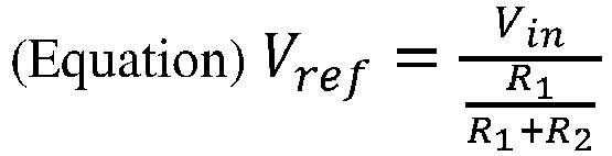
- the case damage determination step determines that there is no damage to the case if the voltage V c measured in the voltage measurement step is the same as the reference voltage V ref , and determines that there is damage to the case if the voltage measured in the voltage measurement step is different from the reference voltage V ref , wherein the reference voltage V ref is calculated by the following (Equation).
- the present invention can detect physical damage to a battery pack case due to external impact.
- FIG. 1 is a cross-sectional view of a battery pack according to an embodiment of the present invention.
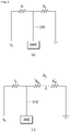
- FIG. 2 is a diagram showing an equivalent circuit of a battery pack according to an embodiment of the present invention.
- FIG. 3 is a flowchart illustrating a case damage detection method of a battery pack according to an embodiment of the present invention.
- the battery pack 10 includes a case 200 in which a plurality of battery cells are accommodated, and a BMS 100 for detecting damage to the case.
- the BMS 100 includes a voltage output terminal 110 for outputting a predetermined voltage, a ground terminal 120, and a voltage measurement terminal 130 for measuring a voltage.
- the BMS 100 includes a battery management function performed by the conventional BMS and may additionally detect damage to the case 200.
- the case 200 is a space in which a plurality of battery cells are mounted, and may be formed of a metal or plastic material.
- the case 200 may include a conductive member 210 in which one end is connected to the voltage output terminal 110 of the BMS 100 and the other end is connected to the ground terminal 120 of the BMS 100 and a sensing wire 220 in which one end is connected to the conductive member 210 and the other end is connected to the voltage measurement terminal 130 of the BMS 100.
- the conductive member 210 may be provided between one surface inside the case 200 and the other surface opposite to the one surface.
- the conductive member 210 is provided between the inner surface of the case 200 and the other surface as described above, it is possible to detect a case where a deformation in which the case 200 is bent inward due to an external impact occurs.
- the conductive member 210 may have a type in which the first conductive member 211 and the second conductive member 212 are connected in series.
- the first conductive member 211 and the second conductive member 212 may have the same resistance.
- the total resistance of the conductive member 210 is different, so that the voltage measured by the sensing wire 220 is different.
- the outside of the conductive member 210 may be sealed with an insulating material.
- a first spring 230 may be provided between one end the conductive member 210 and one surface of the case 200, and a second spring 232 may be provided between the other end of the conductive member 210 and the other surface of the case 200.
- the first and second springs 230 and 232 are intended to provide a margin for detecting damage to the case 200. Specifically, even if the case 200 is bent inward to some extent due to an external impact, as the first and second springs 230 and 232 are contracted, it is possible to prevent the conductive member 210 from being broken due to small bending.
- One end 221 of the sensing wire 220 is electrically connected to the conductive member 210, and the other end is connected to the voltage measurement terminal 130 of the BMS 100.
- one end 221 of the sensing wire 220 may be positioned at the center of the conductive member 210 or between the first conductive member 211 and the second conductive member 212.
- one end 221 of the sensing wire 220 may be positioned anywhere as long as it is electrically connected to the conductive member 210.
- the resistance of the first conductive member 211 may be R1
- the resistance of the second conductive member 212 may be R2
- the predetermined voltage outputted from the voltage output terminal 110 of the BMS 100 may be V in .
- the reference voltage V ref applied to the sensing wire 220 is calculated by (Equation 1).
- V ref V in R 1 R 1 + R 2
- V in voltage outputted from the voltage output terminal
- R1 resistance of the first conductive member
- R2 resistance of the second conductive member
- the voltage V ref applied to the sensing wire 220 becomes a reference value for determining whether the battery pack case is damaged.
- V in /2 which is a voltage corresponding to half of the predetermined voltage V in applied to one end of the conductive member 210, is applied to the sensing wire 220.
- the entire predetermined voltage V in applied to the conductive member 210 may be applied to the sensing wire 220.
- 0 V may be applied to the sensing wire 220.
- the present invention is not limited thereto.
- the voltage applied to the sensing wire 220 may vary in magnitude according to a position where the sensing wire 220 is connected to the conductive member 210.
- the voltage applied to the sensing wire 220 may be measured at the voltage measurement terminal 130 of the BMS.
- the BMS 100 measures the voltage applied to the above-described sensing wire 220 from the voltage measurement terminal 130 of the BMS, and determines whether the case is damaged based on this.
- the reason for this determination is as described in the configuration of the sensing wire 220, because the sensing wire 220 is electrically connected to the conductive member 210, when there is no damage to the battery pack case 200, the voltage applied to the sensing wire satisfies (Equation 1) and, when damage to the battery pack case 200 occur, the voltage applied to the sensing wire 220 varies depending on the location where the damage occurs.
- the voltage applied to the sensing wire 220 varies depending on the position where the conductive member 210 is broken.
- the battery pack according to an embodiment of the present invention may be mounted on a device and used as a power supply source for the device.
- the device may be any one selected from the group consisting of a mobile phone, a tablet computer, a notebook computer, a computer, a power tool, a wearable electronic device, an electric vehicle, a hybrid electric vehicle, a plug-in hybrid electric vehicle, and a power storage device.
- the method for detecting case damage according to an embodiment of the present invention is performed in the battery pack according to the embodiment of the present invention.
- FIG. 3 is a flowchart illustrating a method for detecting damage to a case according to an embodiment of the present invention.
- a case damage detection method according to an embodiment of the present invention will be described with reference to FIG. 3 .
- the case damage detection method includes a voltage application step S 100 of applying a predetermined voltage in the BMS to the conductive member, a voltage measurement step S200 of measuring the voltage applied to the sensing wire in which one end is connected to the center of the conductive member to which the predetermined voltage is applied, and the other end is connected to the voltage measurement terminal of the BMS, and a case damage determination step S300 of determining whether the case is damaged based on the measured voltage.
- the voltage application step S100 is a process for applying a predetermined voltage from the voltage output terminal of the BMS to a conductive member to measure a voltage in the voltage measurement step to be described later.
- the voltage measurement step S200 is a process for measuring a voltage applied to a sensing wire provided at the center of a conductive member, and the measured voltage becomes a criterion for determining whether the case is damaged in the case damage determination step described later.
- the sensing wire when the sensing wire is located at the center of the conductive member or between the same first conductive member and the second conductive member, if the conductive member is not broken, a voltage corresponding to half of the predetermined voltage applied to one end of the conductive member by Equation 1 is applied to the sensing wire.
- the voltage applied to the sensing wire 220 according to the location where the damage occurs may be calculated according to the following (Equation 2).
- V ref V in R 1 R 1 + R 2 a
- Vin voltage outputted from the voltage output terminal
- R1 resistance of the first conductive member
- the voltage applied to the sensing wire 220 varies depending on the position where the conductive member 210 is broken.
- the entire predetermined voltage applied to the conductive member may be applied to the sensing wire.
- the sensing wire may be applied to the sensing wire.
- the voltage applied to the sensing wire is described when the sensing wire is located at the center of the conductive member or between the same first conductive member and the second conductive member, but the present invention is not limited thereto.
- the magnitude of the voltage applied to the sensing wire may vary depending on the position where the sensing wire is connected to the conductive member.
Landscapes
- Chemical & Material Sciences (AREA)
- Chemical Kinetics & Catalysis (AREA)
- Electrochemistry (AREA)
- General Chemical & Material Sciences (AREA)
- Engineering & Computer Science (AREA)
- Manufacturing & Machinery (AREA)
- Microelectronics & Electronic Packaging (AREA)
- Battery Mounting, Suspending (AREA)
- Secondary Cells (AREA)
- Connection Of Batteries Or Terminals (AREA)
Abstract
Description
- The present invention relates to a device and method for detecting damage to a battery pack case due to external impact.
- More specifically, the present invention relates to a device and method for providing a conductor inside a battery pack and detecting damage to a battery pack case based on a voltage measured at the conductor.
- Flat-type batteries such as lithium ion batteries are generally used by being housed in a case made of metal or plastic because they are covered with an exterior material such as a laminate film and are fragile. Recently, a plurality of batteries are electrically connected in series or parallel as a power source for vehicles such as electric vehicles and hybrid vehicles and a battery pack with high output and high capacity is used, and this battery pack is also housed in the case.
- Typically, the battery pack does not separately detect damage to the case of the battery pack, as long as the electrical connection in the BMS is normal.
- On the other hand, if damage occurs to the case in which the battery pack is housed, foreign matter may flow into the damaged part, and problems such as ignition or explosion may occur in the battery pack due to the material introduced from the outside.
- Accordingly, the present invention proposes a device and method for detecting damage to a battery pack case.
- (Patent Document 0001) Japanese Published Patent Publication
JP 2007-059279 A - The present invention provides a battery pack and a detection method capable of detecting physical damage to a battery pack case due to an external shock.
- A battery pack according to an embodiment of the present invention includes a case in which a plurality of battery cells are accommodated; and a BMS configured to detect damage to the case, wherein the BMS includes a voltage output terminal configured to output a predetermined voltage, a ground terminal, and a voltage measurement terminal configured to measure voltage.
- The case includes a conductive member having one end connected to the voltage output terminal of the BMS and the other end connected to the ground terminal of the BMS, and a sensing wire having one end connected to the conductive member and the other end connected to a voltage measurement terminal of the BMS, wherein the conductive member may be provided between one surface inside the case and the other surface opposite to the one surface.
- In the conductive member, a first conductive member and a second conductive member identical to each other are connected in series.
- One end of the sensing wire may be positioned at the center of the conductive member or between the first conductive member and the second conductive member.
- The conductive member may be sealed with an insulating material.
- A first spring may be provided between one end of the conductive member and one surface of the case, wherein a second spring may be provided between the other end of the conductive member and the other surface of the case.
- If a voltage Vc received from the voltage measurement terminal of the BMS is equal to a reference voltage Vref, the BMS determines that there is no damage to the case, and if the voltage Vc received from the voltage measurement terminal of the BMS is different from the reference voltage Vref, the BMS determines that there is damage to the case, wherein the reference voltage Vref is calculated by the following (Equation).

- Meanwhile, the battery pack according to the embodiment of the present invention described above may be mounted on various devices and used as a power source for devices.
- The device is any one selected from the group consisting of a mobile phone, a tablet computer, a notebook computer, a power tool, a wearable electronic device, an electric vehicle, a hybrid electric vehicle, a plug-in hybrid electric vehicle, and a power storage device.
- Moreover, a method of detecting damage to a case of the battery pack according to the above-mentioned embodiment of the present invention includes a voltage application step of applying a predetermined voltage in a BMS to a conductive member; a voltage measurement step of measuring a voltage applied to a sensing wire in which one end is connected to the center of a conductive member to which the predetermined voltage is applied, and the other end is connected to a voltage measurement terminal of a BMS; and a case damage determination step of determining whether the case is damaged based on the measured voltage.
- The case damage determination step determines that there is no damage to the case if the voltage Vc measured in the voltage measurement step is the same as the reference voltage Vref, and determines that there is damage to the case if the voltage measured in the voltage measurement step is different from the reference voltage Vref, wherein the reference voltage Vref is calculated by the following (Equation).

- The present invention can detect physical damage to a battery pack case due to external impact.
- In addition, according to the present invention, by detecting physical damage to the battery pack case due to an external impact, problems such as ignition and explosion of the battery pack due to physical damage to the battery pack case can be prevented.
-
FIG. 1 is a cross-sectional view of a battery pack according to an embodiment of the present invention. -
FIG. 2 is a diagram showing an equivalent circuit of a battery pack according to an embodiment of the present invention. -
FIG. 3 is a flowchart illustrating a case damage detection method of a battery pack according to an embodiment of the present invention. - Hereinafter, embodiments of the present invention will be described in detail with reference to the accompanying drawings so that those of ordinary skill in the art may easily implement the present invention. However, the present invention may be implemented in various forms and is not limited to the embodiments described herein. In the drawings, parts irrelevant to the description are omitted in order to clearly describe the present invention, and like reference numerals refer to like elements throughout the specification.
- The battery pack 10 according to an embodiment of the present invention includes a
case 200 in which a plurality of battery cells are accommodated, and aBMS 100 for detecting damage to the case. - The
BMS 100 includes avoltage output terminal 110 for outputting a predetermined voltage, aground terminal 120, and avoltage measurement terminal 130 for measuring a voltage. - Meanwhile, the
BMS 100 according to an embodiment of the present invention includes a battery management function performed by the conventional BMS and may additionally detect damage to thecase 200. - The
case 200 is a space in which a plurality of battery cells are mounted, and may be formed of a metal or plastic material. - Meanwhile, the
case 200 may include aconductive member 210 in which one end is connected to thevoltage output terminal 110 of theBMS 100 and the other end is connected to theground terminal 120 of theBMS 100 and asensing wire 220 in which one end is connected to theconductive member 210 and the other end is connected to thevoltage measurement terminal 130 of theBMS 100. - The
conductive member 210 may be provided between one surface inside thecase 200 and the other surface opposite to the one surface. - Since the
conductive member 210 is provided between the inner surface of thecase 200 and the other surface as described above, it is possible to detect a case where a deformation in which thecase 200 is bent inward due to an external impact occurs. - Specifically, when the
case 200 is bent inward, theconductive member 210 is disconnected, and as a result, the voltage measured through thesensing wire 220 to be described later varies. - For example, the
conductive member 210 may have a type in which the firstconductive member 211 and the secondconductive member 212 are connected in series. In addition, the firstconductive member 211 and the secondconductive member 212 may have the same resistance. In relation to theconductive member 210 composed of the first and secondconductive members conductive member 211 and the secondconductive member 212 are connected is disconnected, the total resistance of theconductive member 210 is different, so that the voltage measured by thesensing wire 220 is different. - Meanwhile, the outside of the
conductive member 210 may be sealed with an insulating material. - This is to prevent the occurrence of a short circuit when the
conductive member 210 contacts another metal material inside thecase 200. - Meanwhile, a
first spring 230 may be provided between one end theconductive member 210 and one surface of thecase 200, and asecond spring 232 may be provided between the other end of theconductive member 210 and the other surface of thecase 200. - As described above, the first and
second springs case 200. Specifically, even if thecase 200 is bent inward to some extent due to an external impact, as the first andsecond springs conductive member 210 from being broken due to small bending. - One
end 221 of thesensing wire 220 is electrically connected to theconductive member 210, and the other end is connected to thevoltage measurement terminal 130 of theBMS 100. - For example, one
end 221 of thesensing wire 220 may be positioned at the center of theconductive member 210 or between the firstconductive member 211 and the secondconductive member 212. - However, the present invention is not limited thereto, and one
end 221 of thesensing wire 220 may be positioned anywhere as long as it is electrically connected to theconductive member 210. - Hereinafter, a voltage applied to the
sensing wire 220 according to the position where thesensing wire 220 is connected to theconductive member 210 will be described with reference toFIG. 2 . - For example, as shown in (a) of
FIG. 2 , the resistance of the firstconductive member 211 may be R1, the resistance of the secondconductive member 212 may be R2, and the predetermined voltage outputted from thevoltage output terminal 110 of theBMS 100 may be Vin. In this case, when there is no damage to the battery pack case, the reference voltage Vref applied to thesensing wire 220 is calculated by (Equation 1).
- In this way, when there is no damage to the battery pack case, the voltage Vref applied to the
sensing wire 220 becomes a reference value for determining whether the battery pack case is damaged. - Meanwhile, when damage to the battery pack case occurs and one location of the
conductive member 210 is broken, or when there is no damage to the battery pack case, different voltages may be applied to the sensing wire. - For example, when the point 'A' is cut off as shown in (b) of
FIG. 2 , the voltage Vc applied to thesensing wire 220 is calculated by (Equation 2).
- In another example, when the
sensing wire 220 is located at the center of theconductive member 210 or between the firstconductive member 211 and the secondconductive member 212 which are identical to each other, and when theconductive member 210 is not broken, Vin/2, which is a voltage corresponding to half of the predetermined voltage Vin applied to one end of theconductive member 210, is applied to thesensing wire 220. - On the other hand, when the portion where the first
conductive member 211 and the secondconductive member 212 are connected is disconnected, and thesensing wire 220 is connected only to the firstconductive member 211, the entire predetermined voltage Vin applied to theconductive member 210 may be applied to thesensing wire 220. On the other hand, when the connection between the firstconductive member 211 and the secondconductive member 212 is disconnected, and thesensing wire 220 is connected only to the secondconductive member 212, 0 V may be applied to thesensing wire 220. - Meanwhile, in the above-described example, the case where the voltage applied to the
sensing wire 220 is described when thesensing wire 220 is located at the center of theconductive member 210 or between the firstconductive member 211 and the secondconductive member 212 that are the same as each other, but the present invention is not limited thereto. The voltage applied to thesensing wire 220 may vary in magnitude according to a position where thesensing wire 220 is connected to theconductive member 210. - Meanwhile, the voltage applied to the
sensing wire 220 may be measured at thevoltage measurement terminal 130 of the BMS. - For example, the
BMS 100 measures the voltage applied to the above-describedsensing wire 220 from thevoltage measurement terminal 130 of the BMS, and determines whether the case is damaged based on this. - In relation to the BMS, when the voltage received from the
voltage measurement terminal 130 of the above-described BMS satisfies the following (Equation 1), it is determined that there is no damage to thebattery pack case 200, and when the voltage received from thevoltage measurement terminal 130 of the BMS does not satisfy (Equation 1) below the predetermined voltage outputted from thevoltage output terminal 110 of the BMS, it is determined that there is damage to the battery pack case.
- As the reason for this determination is as described in the configuration of the
sensing wire 220, because thesensing wire 220 is electrically connected to theconductive member 210, when there is no damage to thebattery pack case 200, the voltage applied to the sensing wire satisfies (Equation 1) and, when damage to thebattery pack case 200 occur, the voltage applied to thesensing wire 220 varies depending on the location where the damage occurs. - Specifically, referring to (b) of
FIG. 2 , the voltage Vc applied to thesensing wire 200 according to the location where the damage occurs may be calculated according to the following (Equation 2).
- That is, the voltage applied to the
sensing wire 220 varies depending on the position where theconductive member 210 is broken. - Meanwhile, the battery pack according to an embodiment of the present invention may be mounted on a device and used as a power supply source for the device.
- For example, the device may be any one selected from the group consisting of a mobile phone, a tablet computer, a notebook computer, a computer, a power tool, a wearable electronic device, an electric vehicle, a hybrid electric vehicle, a plug-in hybrid electric vehicle, and a power storage device.
- The method for detecting case damage according to an embodiment of the present invention is performed in the battery pack according to the embodiment of the present invention.
-
FIG. 3 is a flowchart illustrating a method for detecting damage to a case according to an embodiment of the present invention. Hereinafter, a case damage detection method according to an embodiment of the present invention will be described with reference toFIG. 3 . - The case damage detection method according to an embodiment of the present invention includes a voltage
application step S 100 of applying a predetermined voltage in the BMS to the conductive member, a voltage measurement step S200 of measuring the voltage applied to the sensing wire in which one end is connected to the center of the conductive member to which the predetermined voltage is applied, and the other end is connected to the voltage measurement terminal of the BMS, and a case damage determination step S300 of determining whether the case is damaged based on the measured voltage. - The voltage application step S100 is a process for applying a predetermined voltage from the voltage output terminal of the BMS to a conductive member to measure a voltage in the voltage measurement step to be described later.
- The voltage measurement step S200 is a process for measuring a voltage applied to a sensing wire provided at the center of a conductive member, and the measured voltage becomes a criterion for determining whether the case is damaged in the case damage determination step described later.
- In relation to the case damage determination step S300, by comparing S310 the voltage measured in the voltage measurement step S200, when the voltage measured in the voltage measurement step S200 is the same as the reference voltage Vref calculated through (Equation 1) below, it may be determined that there is no damage to the case S320, and when the voltage measured in the voltage measurement step S200 is different from the reference voltage Vref calculated through Equation 1 below, it may be determined that there is damage to the battery pack S330.

- For example, when the sensing wire is located at the center of the conductive member or between the same first conductive member and the second conductive member, if the conductive member is not broken, a voltage corresponding to half of the predetermined voltage applied to one end of the conductive member by Equation 1 is applied to the sensing wire.
- However, when the conductive member is cut off as the case is bent inward, the voltage applied to the sensing wire varies.
- Specifically, referring to (b) of
FIG. 2 , the voltage applied to thesensing wire 220 according to the location where the damage occurs may be calculated according to the following (Equation 2).
- That is, the voltage applied to the
sensing wire 220 varies depending on the position where theconductive member 210 is broken. - On the other hand, when the portion where the first conductive member and the second conductive member are connected is disconnected, and the sensing wire is connected only to the first conductive member, the entire predetermined voltage applied to the conductive member may be applied to the sensing wire. On the other hand, when the first conductive member and the second conductive member connected in series are disconnected and the sensing wire is connected only to the second conductive member, 0 V may be applied to the sensing wire.
- Meanwhile, in the above-described example, it is described that the voltage applied to the sensing wire is described when the sensing wire is located at the center of the conductive member or between the same first conductive member and the second conductive member, but the present invention is not limited thereto.
- As for the voltage measured by the sensing wire, the magnitude of the voltage applied to the sensing wire may vary depending on the position where the sensing wire is connected to the conductive member.
- On the other hand, although the technical idea of the present invention has been specifically described according to the above embodiment, it should be noted that the above embodiments are for the purpose of explanation and not limitation. In addition, those skilled in the art in the technical field of the present invention will be able to understand that various embodiments are possible within the scope of the spirit of the present invention.
Claims (10)
- A battery pack comprising:a case in which a plurality of battery cells are accommodated; anda BMS configured to detect damage to the case,wherein the BMS comprises:a voltage output terminal configured to output a predetermined voltage;a ground terminal; anda voltage measurement terminal configured to measure voltage,wherein the case comprises:a conductive member having one end connected to the voltage output terminal of the BMS and the other end connected to the ground terminal of the BMS; anda sensing wire having one end connected to the conductive member and the other end connected to a voltage measurement terminal of the BMS,wherein the conductive member is provided between one surface inside the case and the other surface opposite to the one surface.
- The battery pack of claim 1, wherein in the conductive member, a first conductive member and a second conductive member identical to each other are connected in series.
- The battery pack of claim 2, wherein one end of the sensing wire is positioned at the center of the conductive member or between the first conductive member and the second conductive member.
- The battery pack of claim 1, wherein the conductive member is sealed with an insulating material.
- The battery pack of claim 1, wherein a first spring is provided between the one end of the conductive member and the one surface of the case,
wherein a second spring is provided between the other end of the conductive member and the other surface of the case. - The battery pack of claim 3, wherein if a voltage Vc received from the voltage measurement terminal of the BMS is equal to a reference voltage Vref, the BMS determines that there is no damage to the case, andIf the voltage Vc received from the voltage measurement terminal of the BMS is different from the reference voltage Vref, the BMS determines that there is damage to the case,wherein the reference voltage Vref is calculated by the following (Equation).
 (Vin = voltage outputted from the voltage output terminal, R1 = resistance of the first conductive member, R2 = resistance of the second conductive member)
 - A method of detecting damage to a case of the battery pack according to claim 1, the method comprising:a voltage application step of applying a predetermined voltage in a BMS to a conductive member;a voltage measurement step of measuring a voltage applied to a sensing wire in which one end is connected to the center of a conductive member to which the predetermined voltage is applied, and the other end is connected to a voltage measurement terminal of a BMS; anda case damage determination step of determining whether the case is damaged based on the measured voltage.
- The method of claim 7, wherein the case damage determination stepdetermines that there is no damage to the case if the voltage Vc measured in the voltage measurement step is the same as the reference voltage Vref, anddetermines that there is damage to the case if the voltage measured in the voltage measurement step is different from the reference voltage Vref,wherein the reference voltage Vref is calculated by the following (Equation).
 (Vin = voltage outputted from the voltage output terminal, R1 = resistance of the first conductive member, R2 = resistance of the second conductive member)
 - A device comprising the battery pack according to any one of claims 1 to 6.
- The device of claim 9, wherein the device is any one selected from the group consisting of a mobile phone, a tablet computer, a notebook computer, a power tool, a wearable electronic device, an electric vehicle, a hybrid electric vehicle, a plug-in hybrid electric vehicle, and a power storage device.
Applications Claiming Priority (2)
| Application Number | Priority Date | Filing Date | Title |
|---|---|---|---|
| KR1020200003824A KR102873271B1 (en) | 2020-01-10 | 2020-01-10 | Device and method for detecting damage of battery pack case |
| PCT/KR2020/019422 WO2021141323A1 (en) | 2020-01-10 | 2020-12-30 | Apparatus and method for detecting damage to battery pack case |
Publications (3)
| Publication Number | Publication Date |
|---|---|
| EP4053968A1 true EP4053968A1 (en) | 2022-09-07 |
| EP4053968A4 EP4053968A4 (en) | 2022-12-28 |
| EP4053968B1 EP4053968B1 (en) | 2024-01-31 |
Family
ID=76788788
Family Applications (1)
| Application Number | Title | Priority Date | Filing Date |
|---|---|---|---|
| EP20912750.5A Active EP4053968B1 (en) | 2020-01-10 | 2020-12-30 | Apparatus and method for detecting damage to battery pack case |
Country Status (8)
| Country | Link |
|---|---|
| US (2) | US12407033B2 (en) |
| EP (1) | EP4053968B1 (en) |
| JP (1) | JP7386982B2 (en) |
| KR (1) | KR102873271B1 (en) |
| CN (1) | CN114600297B (en) |
| ES (1) | ES2973840T3 (en) |
| HU (1) | HUE066078T2 (en) |
| WO (1) | WO2021141323A1 (en) |
Family Cites Families (25)
| Publication number | Priority date | Publication date | Assignee | Title |
|---|---|---|---|---|
| JPH07111703A (en) * | 1993-10-08 | 1995-04-25 | Mitsubishi Electric Corp | Vehicle safety equipment |
| KR0164337B1 (en) * | 1995-12-29 | 1999-01-15 | 김태구 | Automotive power disconnect |
| US6100702A (en) | 1997-07-25 | 2000-08-08 | 3M Innovative Properties Company | In-situ fault detection apparatus and method for an encased energy storing device |
| FR2770050B1 (en) * | 1997-10-16 | 1999-12-10 | Alsthom Cge Alcatel | SAFETY DEVICE OF AN ELECTROCHEMICAL ACCUMULATOR |
| CA2262962C (en) * | 1998-05-29 | 2003-04-29 | Myung Soon Bae | Automatic power cut-off device for emergency situations |
| JP3638102B2 (en) * | 1999-09-30 | 2005-04-13 | Necトーキン栃木株式会社 | Battery pack |
| KR20040105486A (en) * | 2003-06-09 | 2004-12-16 | 현대자동차주식회사 | Stack cell voltage detecting apparatus for fuel cell |
| KR100579377B1 (en) | 2004-10-28 | 2006-05-12 | 삼성에스디아이 주식회사 | Secondary battery |
| JP2007059279A (en) | 2005-08-25 | 2007-03-08 | Nissan Motor Co Ltd | Battery housing and battery pack |
| JP2008110744A (en) | 2006-02-07 | 2008-05-15 | Koichi Kizawa | Traveling control device and traveling control method for automobile |
| KR100846709B1 (en) | 2006-10-27 | 2008-07-16 | 삼성에스디아이 주식회사 | Organic electroluminescent display and manufacturing method thereof |
| JP2008258110A (en) | 2007-04-09 | 2008-10-23 | Matsushita Electric Ind Co Ltd | Battery pack |
| JP2009110744A (en) | 2007-10-29 | 2009-05-21 | Sony Corp | Battery pack and impact detection method |
| JP4935893B2 (en) * | 2009-12-24 | 2012-05-23 | 株式会社デンソー | Battery abnormality determination device |
| JP2012154860A (en) | 2011-01-27 | 2012-08-16 | Denso Corp | Damage detection device for on-vehicle electric equipment |
| WO2012143987A1 (en) * | 2011-04-18 | 2012-10-26 | トヨタ自動車株式会社 | Vehicle-use collision detection device |
| EP2631969B1 (en) * | 2012-02-22 | 2021-08-25 | Autoliv Development AB | Battery pack for a vehicle |
| KR102073190B1 (en) * | 2012-08-21 | 2020-02-04 | 삼성에스디아이 주식회사 | Battery pack and controlling method of the same |
| JP5724980B2 (en) * | 2012-09-26 | 2015-05-27 | トヨタ自動車株式会社 | Sealed battery manufacturing method, inspection device, and inspection program |
| KR101619603B1 (en) * | 2014-08-13 | 2016-05-10 | 현대자동차주식회사 | Safety apparatus for battery of vehicle and operating method for the same |
| KR102326548B1 (en) * | 2015-01-08 | 2021-11-16 | 한국과학기술원 | Device for Sensing Crack of Concrete Structure |
| JP2016129178A (en) | 2015-01-09 | 2016-07-14 | 三菱電機株式会社 | Insulating substrate crack detection apparatus, crack detection method, and power module manufacturing method |
| KR102101908B1 (en) * | 2015-10-21 | 2020-04-17 | 주식회사 엘지화학 | Device and method of battery protection circuit |
| JP2017111958A (en) | 2015-12-16 | 2017-06-22 | 昭和電工株式会社 | Negative electrode for lithium ion secondary battery |
| KR102046707B1 (en) | 2018-02-27 | 2019-11-19 | 세종대학교산학협력단 | Techniques of performing convolutional neural network-based gesture recognition using inertial measurement unit |
-
2020
- 2020-01-10 KR KR1020200003824A patent/KR102873271B1/en active Active
- 2020-12-30 HU HUE20912750A patent/HUE066078T2/en unknown
- 2020-12-30 ES ES20912750T patent/ES2973840T3/en active Active
- 2020-12-30 EP EP20912750.5A patent/EP4053968B1/en active Active
- 2020-12-30 CN CN202080071710.7A patent/CN114600297B/en active Active
- 2020-12-30 JP JP2022521477A patent/JP7386982B2/en active Active
- 2020-12-30 US US17/777,140 patent/US12407033B2/en active Active
- 2020-12-30 WO PCT/KR2020/019422 patent/WO2021141323A1/en not_active Ceased
-
2025
- 2025-07-23 US US19/278,241 patent/US20250349919A1/en active Pending
Also Published As
| Publication number | Publication date |
|---|---|
| WO2021141323A1 (en) | 2021-07-15 |
| CN114600297A (en) | 2022-06-07 |
| KR102873271B1 (en) | 2025-10-20 |
| EP4053968A4 (en) | 2022-12-28 |
| KR20210090480A (en) | 2021-07-20 |
| HUE066078T2 (en) | 2024-07-28 |
| US20220399584A1 (en) | 2022-12-15 |
| JP2022553159A (en) | 2022-12-22 |
| US20250349919A1 (en) | 2025-11-13 |
| CN114600297B (en) | 2024-03-08 |
| ES2973840T3 (en) | 2024-06-24 |
| US12407033B2 (en) | 2025-09-02 |
| EP4053968B1 (en) | 2024-01-31 |
| JP7386982B2 (en) | 2023-11-27 |
Similar Documents
| Publication | Publication Date | Title |
|---|---|---|
| US11955828B2 (en) | Battery management apparatus and method using non-destructive resistance analysis | |
| US20240222718A1 (en) | Method and detector for detecting inhomogeneous cell performance of a battery system | |
| CN114902469B (en) | Battery pack and vehicle including the same | |
| EP2811310A1 (en) | State of charge detection device | |
| EP3982137B1 (en) | Soc estimating apparatus and method | |
| US20240142322A1 (en) | Battery Pressure Measuring Sensor and Battery Pressure Measuring Apparatus Including the Same | |
| EP3647803A1 (en) | Apparatus and method for calculating soh of battery pack | |
| EP3998490A1 (en) | Battery management device and method | |
| KR102473230B1 (en) | Apparatus and method for managing battery | |
| EP3722821A1 (en) | Methods, apparatuses, and storage media for calculating short-circuit current of battery | |
| EP3871919B1 (en) | Method and detection unit for detecting inhomogeneous cell performance of a battery system | |
| KR20190106539A (en) | Apparatus for detecting state of secondary battery | |
| EP4053968B1 (en) | Apparatus and method for detecting damage to battery pack case | |
| KR20190071342A (en) | Apparatus and method for diagnosings battery cell | |
| EP4246160A1 (en) | Battery management device and method | |
| US12282068B2 (en) | Lithium precipitation detecting apparatus and method | |
| EP4329046B1 (en) | Battery pack including impact sensing module | |
| JP7543893B2 (en) | Battery pack | |
| KR20180067140A (en) | Method and apparatus for detecting short of a battery cell | |
| EP4468003B1 (en) | Apparatus and method for diagnosing battery | |
| US20250028000A1 (en) | Apparatus and method for monitoring vehicle battery | |
| KR100442985B1 (en) | Method for estimating design capacity of battery loaded on mobile phone | |
| CN121263701A (en) | Apparatus and method for diagnosing battery | |
| CN120731378A (en) | Battery diagnostic device and battery diagnostic method | |
| KR20170090137A (en) | Method for driving of Battery management system |
Legal Events
| Date | Code | Title | Description |
|---|---|---|---|
| STAA | Information on the status of an ep patent application or granted ep patent |
Free format text: STATUS: THE INTERNATIONAL PUBLICATION HAS BEEN MADE |
|
| PUAI | Public reference made under article 153(3) epc to a published international application that has entered the european phase |
Free format text: ORIGINAL CODE: 0009012 |
|
| STAA | Information on the status of an ep patent application or granted ep patent |
Free format text: STATUS: REQUEST FOR EXAMINATION WAS MADE |
|
| 17P | Request for examination filed |
Effective date: 20220602 |
|
| AK | Designated contracting states |
Kind code of ref document: A1 Designated state(s): AL AT BE BG CH CY CZ DE DK EE ES FI FR GB GR HR HU IE IS IT LI LT LU LV MC MK MT NL NO PL PT RO RS SE SI SK SM TR |
|
| A4 | Supplementary search report drawn up and despatched |
Effective date: 20221130 |
|
| RIC1 | Information provided on ipc code assigned before grant |
Ipc: H01M 50/204 20210101ALI20221124BHEP Ipc: H01M 50/244 20210101ALI20221124BHEP Ipc: H01M 10/42 20060101ALI20221124BHEP Ipc: H01M 10/48 20060101AFI20221124BHEP |
|
| DAV | Request for validation of the european patent (deleted) | ||
| DAX | Request for extension of the european patent (deleted) | ||
| GRAP | Despatch of communication of intention to grant a patent |
Free format text: ORIGINAL CODE: EPIDOSNIGR1 |
|
| STAA | Information on the status of an ep patent application or granted ep patent |
Free format text: STATUS: GRANT OF PATENT IS INTENDED |
|
| RIC1 | Information provided on ipc code assigned before grant |
Ipc: H01M 50/204 20210101ALI20230830BHEP Ipc: H01M 50/244 20210101ALI20230830BHEP Ipc: H01M 10/42 20060101ALI20230830BHEP Ipc: H01M 10/48 20060101AFI20230830BHEP |
|
| INTG | Intention to grant announced |
Effective date: 20230925 |
|
| P01 | Opt-out of the competence of the unified patent court (upc) registered |
Effective date: 20231002 |
|
| GRAS | Grant fee paid |
Free format text: ORIGINAL CODE: EPIDOSNIGR3 |
|
| GRAA | (expected) grant |
Free format text: ORIGINAL CODE: 0009210 |
|
| STAA | Information on the status of an ep patent application or granted ep patent |
Free format text: STATUS: THE PATENT HAS BEEN GRANTED |
|
| AK | Designated contracting states |
Kind code of ref document: B1 Designated state(s): AL AT BE BG CH CY CZ DE DK EE ES FI FR GB GR HR HU IE IS IT LI LT LU LV MC MK MT NL NO PL PT RO RS SE SI SK SM TR |
|
| REG | Reference to a national code |
Ref country code: GB Ref legal event code: FG4D Ref country code: CH Ref legal event code: EP |
|
| REG | Reference to a national code |
Ref country code: DE Ref legal event code: R096 Ref document number: 602020025211 Country of ref document: DE |
|
| REG | Reference to a national code |
Ref country code: IE Ref legal event code: FG4D |
|
| REG | Reference to a national code |
Ref country code: LT Ref legal event code: MG9D |
|
| REG | Reference to a national code |
Ref country code: NL Ref legal event code: MP Effective date: 20240131 |
|
| REG | Reference to a national code |
Ref country code: ES Ref legal event code: FG2A Ref document number: 2973840 Country of ref document: ES Kind code of ref document: T3 Effective date: 20240624 |
|
| PG25 | Lapsed in a contracting state [announced via postgrant information from national office to epo] |
Ref country code: IS Free format text: LAPSE BECAUSE OF FAILURE TO SUBMIT A TRANSLATION OF THE DESCRIPTION OR TO PAY THE FEE WITHIN THE PRESCRIBED TIME-LIMIT Effective date: 20240531 |
|
| PG25 | Lapsed in a contracting state [announced via postgrant information from national office to epo] |
Ref country code: LT Free format text: LAPSE BECAUSE OF FAILURE TO SUBMIT A TRANSLATION OF THE DESCRIPTION OR TO PAY THE FEE WITHIN THE PRESCRIBED TIME-LIMIT Effective date: 20240131 |
|
| PG25 | Lapsed in a contracting state [announced via postgrant information from national office to epo] |
Ref country code: GR Free format text: LAPSE BECAUSE OF FAILURE TO SUBMIT A TRANSLATION OF THE DESCRIPTION OR TO PAY THE FEE WITHIN THE PRESCRIBED TIME-LIMIT Effective date: 20240501 |
|
| REG | Reference to a national code |
Ref country code: AT Ref legal event code: MK05 Ref document number: 1654481 Country of ref document: AT Kind code of ref document: T Effective date: 20240131 |
|
| PG25 | Lapsed in a contracting state [announced via postgrant information from national office to epo] |
Ref country code: RS Free format text: LAPSE BECAUSE OF FAILURE TO SUBMIT A TRANSLATION OF THE DESCRIPTION OR TO PAY THE FEE WITHIN THE PRESCRIBED TIME-LIMIT Effective date: 20240430 Ref country code: HR Free format text: LAPSE BECAUSE OF FAILURE TO SUBMIT A TRANSLATION OF THE DESCRIPTION OR TO PAY THE FEE WITHIN THE PRESCRIBED TIME-LIMIT Effective date: 20240131 Ref country code: NL Free format text: LAPSE BECAUSE OF FAILURE TO SUBMIT A TRANSLATION OF THE DESCRIPTION OR TO PAY THE FEE WITHIN THE PRESCRIBED TIME-LIMIT Effective date: 20240131 |
|
| PG25 | Lapsed in a contracting state [announced via postgrant information from national office to epo] |
Ref country code: AT Free format text: LAPSE BECAUSE OF FAILURE TO SUBMIT A TRANSLATION OF THE DESCRIPTION OR TO PAY THE FEE WITHIN THE PRESCRIBED TIME-LIMIT Effective date: 20240131 |
|
| REG | Reference to a national code |
Ref country code: HU Ref legal event code: AG4A Ref document number: E066078 Country of ref document: HU |
|
| PG25 | Lapsed in a contracting state [announced via postgrant information from national office to epo] |
Ref country code: RS Free format text: LAPSE BECAUSE OF FAILURE TO SUBMIT A TRANSLATION OF THE DESCRIPTION OR TO PAY THE FEE WITHIN THE PRESCRIBED TIME-LIMIT Effective date: 20240430 Ref country code: NO Free format text: LAPSE BECAUSE OF FAILURE TO SUBMIT A TRANSLATION OF THE DESCRIPTION OR TO PAY THE FEE WITHIN THE PRESCRIBED TIME-LIMIT Effective date: 20240430 Ref country code: NL Free format text: LAPSE BECAUSE OF FAILURE TO SUBMIT A TRANSLATION OF THE DESCRIPTION OR TO PAY THE FEE WITHIN THE PRESCRIBED TIME-LIMIT Effective date: 20240131 Ref country code: LT Free format text: LAPSE BECAUSE OF FAILURE TO SUBMIT A TRANSLATION OF THE DESCRIPTION OR TO PAY THE FEE WITHIN THE PRESCRIBED TIME-LIMIT Effective date: 20240131 Ref country code: IS Free format text: LAPSE BECAUSE OF FAILURE TO SUBMIT A TRANSLATION OF THE DESCRIPTION OR TO PAY THE FEE WITHIN THE PRESCRIBED TIME-LIMIT Effective date: 20240531 Ref country code: HR Free format text: LAPSE BECAUSE OF FAILURE TO SUBMIT A TRANSLATION OF THE DESCRIPTION OR TO PAY THE FEE WITHIN THE PRESCRIBED TIME-LIMIT Effective date: 20240131 Ref country code: GR Free format text: LAPSE BECAUSE OF FAILURE TO SUBMIT A TRANSLATION OF THE DESCRIPTION OR TO PAY THE FEE WITHIN THE PRESCRIBED TIME-LIMIT Effective date: 20240501 Ref country code: FI Free format text: LAPSE BECAUSE OF FAILURE TO SUBMIT A TRANSLATION OF THE DESCRIPTION OR TO PAY THE FEE WITHIN THE PRESCRIBED TIME-LIMIT Effective date: 20240131 Ref country code: BG Free format text: LAPSE BECAUSE OF FAILURE TO SUBMIT A TRANSLATION OF THE DESCRIPTION OR TO PAY THE FEE WITHIN THE PRESCRIBED TIME-LIMIT Effective date: 20240131 Ref country code: AT Free format text: LAPSE BECAUSE OF FAILURE TO SUBMIT A TRANSLATION OF THE DESCRIPTION OR TO PAY THE FEE WITHIN THE PRESCRIBED TIME-LIMIT Effective date: 20240131 |
|
| PG25 | Lapsed in a contracting state [announced via postgrant information from national office to epo] |
Ref country code: PL Free format text: LAPSE BECAUSE OF FAILURE TO SUBMIT A TRANSLATION OF THE DESCRIPTION OR TO PAY THE FEE WITHIN THE PRESCRIBED TIME-LIMIT Effective date: 20240131 Ref country code: PT Free format text: LAPSE BECAUSE OF FAILURE TO SUBMIT A TRANSLATION OF THE DESCRIPTION OR TO PAY THE FEE WITHIN THE PRESCRIBED TIME-LIMIT Effective date: 20240531 |
|
| PG25 | Lapsed in a contracting state [announced via postgrant information from national office to epo] |
Ref country code: SE Free format text: LAPSE BECAUSE OF FAILURE TO SUBMIT A TRANSLATION OF THE DESCRIPTION OR TO PAY THE FEE WITHIN THE PRESCRIBED TIME-LIMIT Effective date: 20240131 Ref country code: PT Free format text: LAPSE BECAUSE OF FAILURE TO SUBMIT A TRANSLATION OF THE DESCRIPTION OR TO PAY THE FEE WITHIN THE PRESCRIBED TIME-LIMIT Effective date: 20240531 Ref country code: PL Free format text: LAPSE BECAUSE OF FAILURE TO SUBMIT A TRANSLATION OF THE DESCRIPTION OR TO PAY THE FEE WITHIN THE PRESCRIBED TIME-LIMIT Effective date: 20240131 Ref country code: LV Free format text: LAPSE BECAUSE OF FAILURE TO SUBMIT A TRANSLATION OF THE DESCRIPTION OR TO PAY THE FEE WITHIN THE PRESCRIBED TIME-LIMIT Effective date: 20240131 |
|
| PG25 | Lapsed in a contracting state [announced via postgrant information from national office to epo] |
Ref country code: DK Free format text: LAPSE BECAUSE OF FAILURE TO SUBMIT A TRANSLATION OF THE DESCRIPTION OR TO PAY THE FEE WITHIN THE PRESCRIBED TIME-LIMIT Effective date: 20240131 |
|
| PG25 | Lapsed in a contracting state [announced via postgrant information from national office to epo] |
Ref country code: SM Free format text: LAPSE BECAUSE OF FAILURE TO SUBMIT A TRANSLATION OF THE DESCRIPTION OR TO PAY THE FEE WITHIN THE PRESCRIBED TIME-LIMIT Effective date: 20240131 |
|
| PG25 | Lapsed in a contracting state [announced via postgrant information from national office to epo] |
Ref country code: CZ Free format text: LAPSE BECAUSE OF FAILURE TO SUBMIT A TRANSLATION OF THE DESCRIPTION OR TO PAY THE FEE WITHIN THE PRESCRIBED TIME-LIMIT Effective date: 20240131 Ref country code: EE Free format text: LAPSE BECAUSE OF FAILURE TO SUBMIT A TRANSLATION OF THE DESCRIPTION OR TO PAY THE FEE WITHIN THE PRESCRIBED TIME-LIMIT Effective date: 20240131 |
|
| PG25 | Lapsed in a contracting state [announced via postgrant information from national office to epo] |
Ref country code: SK Free format text: LAPSE BECAUSE OF FAILURE TO SUBMIT A TRANSLATION OF THE DESCRIPTION OR TO PAY THE FEE WITHIN THE PRESCRIBED TIME-LIMIT Effective date: 20240131 |
|
| PG25 | Lapsed in a contracting state [announced via postgrant information from national office to epo] |
Ref country code: SM Free format text: LAPSE BECAUSE OF FAILURE TO SUBMIT A TRANSLATION OF THE DESCRIPTION OR TO PAY THE FEE WITHIN THE PRESCRIBED TIME-LIMIT Effective date: 20240131 Ref country code: SK Free format text: LAPSE BECAUSE OF FAILURE TO SUBMIT A TRANSLATION OF THE DESCRIPTION OR TO PAY THE FEE WITHIN THE PRESCRIBED TIME-LIMIT Effective date: 20240131 Ref country code: RO Free format text: LAPSE BECAUSE OF FAILURE TO SUBMIT A TRANSLATION OF THE DESCRIPTION OR TO PAY THE FEE WITHIN THE PRESCRIBED TIME-LIMIT Effective date: 20240131 Ref country code: EE Free format text: LAPSE BECAUSE OF FAILURE TO SUBMIT A TRANSLATION OF THE DESCRIPTION OR TO PAY THE FEE WITHIN THE PRESCRIBED TIME-LIMIT Effective date: 20240131 Ref country code: DK Free format text: LAPSE BECAUSE OF FAILURE TO SUBMIT A TRANSLATION OF THE DESCRIPTION OR TO PAY THE FEE WITHIN THE PRESCRIBED TIME-LIMIT Effective date: 20240131 Ref country code: CZ Free format text: LAPSE BECAUSE OF FAILURE TO SUBMIT A TRANSLATION OF THE DESCRIPTION OR TO PAY THE FEE WITHIN THE PRESCRIBED TIME-LIMIT Effective date: 20240131 |
|
| REG | Reference to a national code |
Ref country code: DE Ref legal event code: R097 Ref document number: 602020025211 Country of ref document: DE |
|
| PG25 | Lapsed in a contracting state [announced via postgrant information from national office to epo] |
Ref country code: IT Free format text: LAPSE BECAUSE OF FAILURE TO SUBMIT A TRANSLATION OF THE DESCRIPTION OR TO PAY THE FEE WITHIN THE PRESCRIBED TIME-LIMIT Effective date: 20240131 |
|
| PLBE | No opposition filed within time limit |
Free format text: ORIGINAL CODE: 0009261 |
|
| STAA | Information on the status of an ep patent application or granted ep patent |
Free format text: STATUS: NO OPPOSITION FILED WITHIN TIME LIMIT |
|
| PG25 | Lapsed in a contracting state [announced via postgrant information from national office to epo] |
Ref country code: IT Free format text: LAPSE BECAUSE OF FAILURE TO SUBMIT A TRANSLATION OF THE DESCRIPTION OR TO PAY THE FEE WITHIN THE PRESCRIBED TIME-LIMIT Effective date: 20240131 |
|
| 26N | No opposition filed |
Effective date: 20241101 |
|
| PG25 | Lapsed in a contracting state [announced via postgrant information from national office to epo] |
Ref country code: SI Free format text: LAPSE BECAUSE OF FAILURE TO SUBMIT A TRANSLATION OF THE DESCRIPTION OR TO PAY THE FEE WITHIN THE PRESCRIBED TIME-LIMIT Effective date: 20240131 |
|
| PG25 | Lapsed in a contracting state [announced via postgrant information from national office to epo] |
Ref country code: MC Free format text: LAPSE BECAUSE OF FAILURE TO SUBMIT A TRANSLATION OF THE DESCRIPTION OR TO PAY THE FEE WITHIN THE PRESCRIBED TIME-LIMIT Effective date: 20240131 |
|
| REG | Reference to a national code |
Ref country code: CH Ref legal event code: PL |
|
| PG25 | Lapsed in a contracting state [announced via postgrant information from national office to epo] |
Ref country code: LU Free format text: LAPSE BECAUSE OF NON-PAYMENT OF DUE FEES Effective date: 20241230 |
|
| PG25 | Lapsed in a contracting state [announced via postgrant information from national office to epo] |
Ref country code: CH Free format text: LAPSE BECAUSE OF NON-PAYMENT OF DUE FEES Effective date: 20241231 |
|
| PG25 | Lapsed in a contracting state [announced via postgrant information from national office to epo] |
Ref country code: IE Free format text: LAPSE BECAUSE OF NON-PAYMENT OF DUE FEES Effective date: 20241230 |
|
| PGFP | Annual fee paid to national office [announced via postgrant information from national office to epo] |
Ref country code: DE Payment date: 20251120 Year of fee payment: 6 |
|
| PGFP | Annual fee paid to national office [announced via postgrant information from national office to epo] |
Ref country code: GB Payment date: 20251120 Year of fee payment: 6 |
|
| PGFP | Annual fee paid to national office [announced via postgrant information from national office to epo] |
Ref country code: HU Payment date: 20251216 Year of fee payment: 6 Ref country code: FR Payment date: 20251125 Year of fee payment: 6 |
|
| PGFP | Annual fee paid to national office [announced via postgrant information from national office to epo] |
Ref country code: BE Payment date: 20251120 Year of fee payment: 6 |
|
| PGFP | Annual fee paid to national office [announced via postgrant information from national office to epo] |
Ref country code: ES Payment date: 20260122 Year of fee payment: 6 |