EP4053963A1 - Battery swelling test device - Google Patents
Battery swelling test device Download PDFInfo
- Publication number
- EP4053963A1 EP4053963A1 EP21771862.6A EP21771862A EP4053963A1 EP 4053963 A1 EP4053963 A1 EP 4053963A1 EP 21771862 A EP21771862 A EP 21771862A EP 4053963 A1 EP4053963 A1 EP 4053963A1
- Authority
- EP
- European Patent Office
- Prior art keywords
- swelling
- inspection apparatus
- pressing member
- battery
- pressure
- Prior art date
- Legal status (The legal status is an assumption and is not a legal conclusion. Google has not performed a legal analysis and makes no representation as to the accuracy of the status listed.)
- Granted
Links
Images


Classifications
-
- G—PHYSICS
- G01—MEASURING; TESTING
- G01B—MEASURING LENGTH, THICKNESS OR SIMILAR LINEAR DIMENSIONS; MEASURING ANGLES; MEASURING AREAS; MEASURING IRREGULARITIES OF SURFACES OR CONTOURS
- G01B21/00—Measuring arrangements or details thereof, where the measuring technique is not covered by the other groups of this subclass, unspecified or not relevant
- G01B21/32—Measuring arrangements or details thereof, where the measuring technique is not covered by the other groups of this subclass, unspecified or not relevant for measuring the deformation in a solid
-
- G—PHYSICS
- G01—MEASURING; TESTING
- G01B—MEASURING LENGTH, THICKNESS OR SIMILAR LINEAR DIMENSIONS; MEASURING ANGLES; MEASURING AREAS; MEASURING IRREGULARITIES OF SURFACES OR CONTOURS
- G01B5/00—Measuring arrangements characterised by the use of mechanical techniques
- G01B5/30—Measuring arrangements characterised by the use of mechanical techniques for measuring the deformation in a solid, e.g. mechanical strain gauge
-
- H—ELECTRICITY
- H01—ELECTRIC ELEMENTS
- H01M—PROCESSES OR MEANS, e.g. BATTERIES, FOR THE DIRECT CONVERSION OF CHEMICAL ENERGY INTO ELECTRICAL ENERGY
- H01M10/00—Secondary cells; Manufacture thereof
- H01M10/05—Accumulators with non-aqueous electrolyte
- H01M10/052—Li-accumulators
-
- H—ELECTRICITY
- H01—ELECTRIC ELEMENTS
- H01M—PROCESSES OR MEANS, e.g. BATTERIES, FOR THE DIRECT CONVERSION OF CHEMICAL ENERGY INTO ELECTRICAL ENERGY
- H01M10/00—Secondary cells; Manufacture thereof
- H01M10/42—Methods or arrangements for servicing or maintenance of secondary cells or secondary half-cells
- H01M10/4285—Testing apparatus
-
- H—ELECTRICITY
- H01—ELECTRIC ELEMENTS
- H01M—PROCESSES OR MEANS, e.g. BATTERIES, FOR THE DIRECT CONVERSION OF CHEMICAL ENERGY INTO ELECTRICAL ENERGY
- H01M10/00—Secondary cells; Manufacture thereof
- H01M10/42—Methods or arrangements for servicing or maintenance of secondary cells or secondary half-cells
- H01M10/48—Accumulators combined with arrangements for measuring, testing or indicating the condition of cells, e.g. the level or density of the electrolyte
-
- H—ELECTRICITY
- H01—ELECTRIC ELEMENTS
- H01M—PROCESSES OR MEANS, e.g. BATTERIES, FOR THE DIRECT CONVERSION OF CHEMICAL ENERGY INTO ELECTRICAL ENERGY
- H01M50/00—Constructional details or processes of manufacture of the non-active parts of electrochemical cells other than fuel cells, e.g. hybrid cells
- H01M50/20—Mountings; Secondary casings or frames; Racks, modules or packs; Suspension devices; Shock absorbers; Transport or carrying devices; Holders
- H01M50/204—Racks, modules or packs for multiple batteries or multiple cells
- H01M50/207—Racks, modules or packs for multiple batteries or multiple cells characterised by their shape
- H01M50/209—Racks, modules or packs for multiple batteries or multiple cells characterised by their shape adapted for prismatic or rectangular cells
-
- H—ELECTRICITY
- H01—ELECTRIC ELEMENTS
- H01M—PROCESSES OR MEANS, e.g. BATTERIES, FOR THE DIRECT CONVERSION OF CHEMICAL ENERGY INTO ELECTRICAL ENERGY
- H01M50/00—Constructional details or processes of manufacture of the non-active parts of electrochemical cells other than fuel cells, e.g. hybrid cells
- H01M50/20—Mountings; Secondary casings or frames; Racks, modules or packs; Suspension devices; Shock absorbers; Transport or carrying devices; Holders
- H01M50/233—Mountings; Secondary casings or frames; Racks, modules or packs; Suspension devices; Shock absorbers; Transport or carrying devices; Holders characterised by physical properties of casings or racks, e.g. dimensions
- H01M50/242—Mountings; Secondary casings or frames; Racks, modules or packs; Suspension devices; Shock absorbers; Transport or carrying devices; Holders characterised by physical properties of casings or racks, e.g. dimensions adapted for protecting batteries against vibrations, collision impact or swelling
-
- Y—GENERAL TAGGING OF NEW TECHNOLOGICAL DEVELOPMENTS; GENERAL TAGGING OF CROSS-SECTIONAL TECHNOLOGIES SPANNING OVER SEVERAL SECTIONS OF THE IPC; TECHNICAL SUBJECTS COVERED BY FORMER USPC CROSS-REFERENCE ART COLLECTIONS [XRACs] AND DIGESTS
- Y02—TECHNOLOGIES OR APPLICATIONS FOR MITIGATION OR ADAPTATION AGAINST CLIMATE CHANGE
- Y02E—REDUCTION OF GREENHOUSE GAS [GHG] EMISSIONS, RELATED TO ENERGY GENERATION, TRANSMISSION OR DISTRIBUTION
- Y02E60/00—Enabling technologies; Technologies with a potential or indirect contribution to GHG emissions mitigation
- Y02E60/10—Energy storage using batteries
Definitions
- the present disclosure relates to a battery swelling inspection apparatus, and more particularly, to a battery swelling inspection apparatus capable of inspecting swelling of a battery cell.
- Batteries commercially available at present include nickel-cadmium batteries, nickel hydrogen batteries, nickel-zinc batteries, lithium batteries and the like.
- the lithium batteries are in the limelight since they have almost no memory effect compared to nickel-based batteries and also have very low self-charging rate and high energy density.
- Such a battery may cause swelling in which gas is generated in the battery during charging and discharging or in a high temperature state to inflate the battery. Since there is a risk of fire or explosion due to battery swelling, it is important to accurately inspect the swelling behavior of the battery.
- Patent Document 1 a device for inspecting swelling of a battery using a plurality of load cells has been disclosed (Patent Document 1).
- a first plate, a plurality of load cells, a second plate, a measurement target (a battery cell) and a third plate are stacked, and the first plate, the second plate and the third plate are fixed using a plurality of fastening members.
- the second plate provided between the battery cell and the plurality of load cells is fixed by the fastening member, the swelling pressure of each region of the battery cell transmitted to the plurality of load cells is inevitably lost seriously. That is, in Patent Document 1, since the movement of the second plate caused by the swelling pressure is restricted by the fastening member, there is a limitation in that the swelling of the battery cell may not be accurately inspected.
- FIG. 9 of Patent Document 1 a structure in which the second plate is composed of a plurality of partial flat plates and the partial flat plates are connected to each other by a connection unit is disclosed. Since the partial flat plates are connected to each other, there is a problem that the swelling pressure applied to one of the partial flat plates may affect the other partial flat plates.
- the plurality of partial flat plates of Patent Document 1 are restricted to each other by the connecting unit made of a material having elasticity or ductility. That is, if a swelling pressure is applied to any one partial flat plate, the swelling pressure is not transmitted only to the load cell located in a lower direction, but is distributed through the connection unit.
- Patent Document 1 KR 10-2017-0042082 A
- the present disclosure is designed to solve the problems of the related art, and therefore the present disclosure is directed to providing a battery swelling inspection apparatus capable of independently measuring the pressure of each region of a battery cell corresponding to each of a plurality of pressure measuring elements.
- a battery swelling inspection apparatus comprising: a lower plate configured in a plate shape; an upper plate configured in a plate shape and located to face the lower plate; a fixing frame configured such that a portion of the lower plate and a portion of the upper plate are fixedly coupled thereto; a plurality of pressure measuring elements fixedly coupled to the lower plate, having a head located to face the upper plate, and configured to measure a pressure applied to the head, respectively; and a plurality of pressing members configured to have an upper surface in a flat shape so that the upper surface faces the upper plate and have a lower surface that is at least partially attached to the head of each of the plurality of pressure measuring elements.
- the pressure measuring element may be configured such that at least a portion of the head is inclined.
- the pressure measuring element may be configured such that at least a portion of the head has a curved surface.
- the pressing member may be configured such that a center portion of the lower surface thereof is attached to the head.
- the pressing member may be configured such that the upper surface thereof faces the upper plate at a predetermined interval.
- the fixing frame may be configured such that the interval between the upper surface of the pressing member and the upper plate is adjustable.
- the pressing member may include: a body portion configured in a plate shape having the upper surface and the lower surface; and a leg portion configured to protrude in a lower direction from at least a portion of the body portion.
- the pressing member may be configured such that an angle between the body portion and the leg portion is changeable.
- the leg portion may be coupled with at least a portion of the body portion and configured to enable hinge rotation thereat.
- a battery swelling inspection apparatus may further comprise an elastic member configured to have one end attached to the lower plate and the other end attached to the leg portion.
- the body portion may be configured to be inclinable based on the head to correspond to a location where a pressure is applied.
- the leg portion may be configured to be movable in an upper direction or in a lower direction by the elastic member that contracts or expands depending on the degree of inclination of the body portion.
- a battery swelling inspection apparatus may further comprise a support member configured to have one end attached to the lower plate and have a hollow or a groove so that the leg portion is inserted therein.
- the elastic member may be configured to be located in the hollow or the groove.
- a battery swelling inspection apparatus may further comprise a guide member configured to protrude in an upper direction from an upper surface of the lower plate so that the upper surface of the lower plate is divided into a plurality of sections.
- a battery swelling inspection apparatus may further comprise a control unit connected to the plurality of pressure measuring elements and configured to receive a measured pressure value from each of the plurality of pressure measuring elements and, when a battery cell is interposed between the upper plate and the pressing member, determine at least one of a swelling distribution of the battery cell and a swelling degree of each region of the battery cell based on the plurality of received pressure values.
- the swelling distribution of the battery cell and/or the swelling degree of each region of the battery cell may be more accurately measured.
- control unit refers to a unit that processes at least one function or operation, and may be implemented by hardware, software, or a combination of hardware and software.
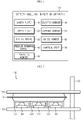
- FIG. 1 is a block diagram schematically showing a battery swelling inspection apparatus 100 according to an embodiment of the present disclosure.
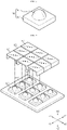
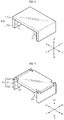
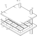
- FIG. 2 is a diagram schematically showing the battery swelling inspection apparatus 100 according to an embodiment of the present disclosure.
- the battery swelling inspection apparatus 100 is a device for inspecting swelling of a battery cell 10, and may inspect a swelling distribution and/or a swelling degree.
- the battery cell 10 refers to one independent cell that has a negative electrode terminal and a positive electrode terminal and is physically separable.
- one pouch-type lithium polymer cell may be regarded as a battery cell.
- battery swelling in which the battery cell 10 is inflated, may occur not only at a center portion of the battery cell 10 but also at a peripheral portion thereof.
- the peripheral portion refers to an area excluding the center portion.
- the battery swelling inspection apparatus 100 may inspect a pressure distribution (a swelling distribution) of the battery cell 10 caused by swelling and/or a pressure level (a swelling degree) of each region of the battery cell 10 caused by swelling.
- the battery swelling inspection apparatus 100 may include a lower plate 110, an upper plate 120, a fixing frame 130, a pressure measuring element 140, and a pressing member 150.
- the lower plate 110 may be configured in a plate shape.
- the lower plate 110 may be configured in a plate shape so that a plurality of pressure measuring elements 140 may be attached thereto.
- the lower plate 110 may be configured in a flat plate shape.
- the upper plate 120 may be configured in a plate shape and located to face the lower plate 110.
- the upper plate 120 may be configured in a flat plate shape so that a lower surface of the upper plate 120 contacts an upper surface of the battery cell 10.
- the upper plate 120 and the battery cell 10 may be attached and detached.
- the upper surface of the battery cell 10 may be attached to the lower surface of upper plate 120.
- the battery cell 10 may be detached from the upper plate 120.
- the upper plate 120 and the lower plate 110 may be located to face each other.
- the upper plate 120 and the lower plate 110 are located to face each other, and the battery cell 10 may be provided between the upper plate 120 and the lower plate 110.
- the fixing frame 130 may be configured such that a portion of the lower plate 110 and a portion of the upper plate 120 are fixedly coupled thereto.
- the fixing frame 130 may fix the upper plate 120 and the lower plate 110 so that the upper plate 120 and the lower plate 110 are not shaken or rotated.
- the pressure measuring element 140 may be provided in plural. In addition, the plurality of pressure measuring elements 140 may be fixedly coupled to the lower plate 110.
- the number of the pressure measuring elements 140 included in the battery swelling inspection apparatus 100 is not limited. However, if a larger number of pressure measuring elements 140 are provided, the accuracy of the swelling inspection may be improved. Hereinafter, for convenience of description, it will be described that nine pressure measuring elements 140 are provided.
- the plurality of pressure measuring elements 140 may be fixedly coupled to the lower plate 110 to be spaced apart from each other at a constant interval.
- the plurality of pressure measuring elements 140 may be biased and fixedly coupled to a portion of the lower plate 110, the swelling distribution of the battery cell 10 may not be accurately measured. Accordingly, the plurality of pressure measuring elements 140 may be disposed on the lower plate 110 at predetermined intervals.
- the pressure measuring element 140 may be located so that a head 141 thereof faces the upper plate 120 and may be configured to measure a pressure applied to the head 141, respectively.
- FIG. 3 is a diagram showing the pressure measuring element 140 of the battery swelling inspection apparatus 100 according to an embodiment of the present disclosure.
- the pressure measuring element 140 may include a head 141 and a body 142.
- the pressure measuring element 140 may be configured to measure a pressure applied to the head 141.
- a load cell may be applied as the pressure measuring element 140.
- a swelling pressure may be applied to the head 141 of each of the plurality of pressure measuring elements 140.
- Each of the plurality of pressure measuring elements 140 may measure the swelling pressure applied to the head 141.
- the swelling pressures measured by the plurality of pressure measuring elements 140 differs from each other according to locations where swelling occurs in the battery cell 10.
- the pressing member 150 may be provided in plural. Preferably, the number of the pressing members 150 may correspond to the number of the plurality of pressure measuring elements 140.
- the pressing member 150 may be configured such that an upper surface thereof is formed in a flat shape and the upper surface thereof faces the upper plate 120.
- the battery cell 10 may be interposed between the pressing member 150 and the upper plate 120.
- the upper surface of the pressing member 150 may be formed in a flat shape so that the swelling pressure of the battery cell 10 may be applied to the pressing member 150 when the upper surface of the pressing member 150 contacts the battery cell 10.
- the battery cell 10 may be interposed and fixed between the upper surface of the pressing member 150 and the upper plate 120.
- the pressing member 150 may be configured such that at least a portion of the lower surface thereof is attached to the head 141 of each of the plurality of pressure measuring elements 140.
- the head 141 of the pressure measuring element 140 and the pressing member 150 may be made of magnetic materials that may be attached to each other. More preferably, an upper end of the head 141 of the pressure measuring element 140 and a center portion of the lower surface of the pressing member 150 may be made of magnetic materials. Accordingly, by magnetism, the center portion of the lower surface of the pressing member 150 may be attached to the upper end of the head 141 of the pressure measuring element 140. In addition, the pressing member 150 may be attached to and detached from the head 141 of the pressure measuring element 140.
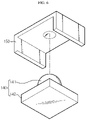
- FIG. 4 is an exploded perspective view showing the pressure measuring element 140 and the pressing member 150, in the battery swelling inspection apparatus 100 according to an embodiment of the present disclosure.
- FIG. 5 is an assembled perspective view showing the pressure measuring element 140 and the pressing member 150, in the battery swelling inspection apparatus 100 according to an embodiment of the present disclosure.
- the plurality of pressing members 150 may be attached to the corresponding pressure measuring elements 140. That is, the plurality of pressing members 150 and the plurality of pressure measuring elements 140 may correspond to each other in one-to-one relationship.
- the center portion of the lower surface (a surface in -z direction) of the pressing member 150 may be attached to the upper end (the upper end in the +z direction) of the head 141.
- the pressing member 150 may be attached to the head 141 of the pressure measuring element 140 such that the upper surface (a surface in +z direction) thereof is parallel to the lower plate 110.
- the plurality of pressing members 150 may be spaced apart from each other by a predetermined distance.
- a first pressing member 150 corresponds to a first pressure measuring element 140a and a second pressing member 150 corresponds to a second pressure measuring element 140b. If the swelling pressure of the battery is applied to the first pressing member 150, the first pressing member 150 may transmit the swelling pressure to the head 141 of the first pressure measuring element 140a. That is, pressure in a lower direction (-z direction) is applied to the first pressing member 150 by the swelling pressure, and the swelling pressure may be transmitted to the head 141 of the first pressure measuring element 140a through the first pressing member 150. Since the first pressing member 150 and the second pressing member 150 are separated by a predetermined distance and do not contact each other, the swelling pressure applied to the first pressing member 150 may not have a direct effect on the second pressing member 150.
- the pressure measuring element 140 may be configured such that at least a portion of the head 141 is inclined.
- the pressing member 150 may be pressed by the applied swelling pressure.
- the pressing member 150 may be inclined to correspond to the location where the swelling pressure is applied.
- the pressing member 150 may be inclined based on the upper end of the head 141. That is, the center portion of the lower surface of the pressing member 150 (the portion attached to the upper end of the head 141) may act as a supporting point.
- the body 142 of the pressure measuring element 140 is fixedly coupled to the lower plate 110, and the head 141 of the pressure measuring element 140 is movable in a vertical direction.
- the head 141 may move in an upper direction (+z direction) and a lower direction (-z direction). Therefore, as in the previous example, a portion of the upper end of the head 141 (the upper end in the +z direction) of the pressure measuring element 140 to which the pressing member 150 is attached may be configured in an inclined shape so that the force applied to the pressing member 150 may be transmitted to the head 141 of the pressure measuring element 140 in a better way while the pressing member 150 is being inclined.
- At least a portion of the head 141 of the pressure measuring element 140 may have an angular shape or a curved shape.
- at least a portion of the head 141 may be configured to have a curved surface.
- the pressing member 150 when the pressing member 150 is inclined as the swelling pressure is applied to the pressing member 150, it is possible to minimize that the movement of the pressing member 150 is restricted by the shape of the head 141 of the pressure measuring element 140. That is, since the head 141 of the pressure measuring element 140 is configured such that the pressing member 150 may be easily inclined, the pressing member 150 may be easily inclined in response to the applied pressure.
- the pressing member 150 may be configured to easily return to its original shape after being inclined.
- FIG. 6 is a diagram showing another embodiment of the pressing member 150, in the battery swelling inspection apparatus 100 according to an embodiment of the present disclosure.
- a groove corresponding to the head 141 of the pressure measuring element 140 may be provided in the center portion of the lower surface of the pressing member 150.
- the curvature of the groove in the lower surface of the pressing member 150 may be less than or equal to the curvature of the upper end of the head 141 of the pressure measuring element 140.
- the groove of the lower surface of the pressing member 150 and the upper end of the head 141 of the pressure measuring element 140 may be magnetically attached to each other.
- the swelling pressure is applied to the pressing member 150, the pressing member 150 may be easily inclined along the head 141 of the pressure measuring element 140.
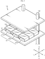
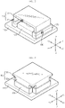
- FIG. 7 is a diagram schematically showing the battery swelling inspection apparatus according 100 to an embodiment of the present disclosure.
- the pressing member 150 may be configured such that the upper surface thereof faces the upper plate 120 at a predetermined interval.
- the fixing frame 130 may be configured to adjust the interval between the upper surface of the pressing member and the upper plate 120.
- the fixing frame 130 may be configured to adjust a location where the lower plate 110 and the upper plate 120 are coupled.
- the location in the fixing frame 130 at which the lower plate 110 and the upper plate 120 are fixedly coupled may be adjusted so that the battery cell 10 may be fixed between the pressing member 150 and the upper plate 120. Accordingly, the interval between the upper surface of the pressing member 150 and the lower surface of the upper plate 120 may be adjusted.
- the fixing frame 130 may be configured to adjust the position where which the lower plate 110 and the upper plate 120 are fixed in a vertical direction (z direction).
- the battery swelling inspection apparatus 100 since the battery swelling inspection apparatus 100 according to an embodiment of the present disclosure includes the fixing frame 130 configured to adjust the interval between the lower plate 110 and the upper plate 120, and there is an advantage in that swelling of battery cells 10 having various thicknesses (for example, z-direction length of the battery cell 10 in FIG. 7 ) may be inspected.
- FIG. 8 is a diagram showing another embodiment of the pressing member 150, in the battery swelling inspection apparatus 100 according to an embodiment of the present disclosure.
- the pressing member 150 may include a body portion 151 and a leg portion 152.
- the body portion 151 may be configured in a plate shape having the upper surface and the lower surface.
- the leg portion 152 may be configured to protrude in a lower direction from at least a portion of the body portion 151.
- the body portion 151 may be configured in a plate shape having an upper surface (a surface in +z direction) and a lower surface (a surface in -z direction).
- the leg portion 152 may protrude in a lower direction (-z direction) from a portion of the body portion 151.
- the swelling pressure of the battery cell 10 may not be accurately transmitted to the pressure measuring element 140 corresponding to the inclined pressing member 150.
- the accuracy of the swelling distribution of the battery cell 10 inspected by the plurality of pressure measuring elements 140 may be lowered.
- the plurality of pressure measuring elements 140 may be disposed on the lower plate 110 with a predetermined interval therebetween so that any one pressing member 150 does not contact the adjacent pressing member 150 even though rotating.
- the pressing member 150 may be configured such that an angle between the body portion 151 and the leg portion 152 is changeable.
- FIG. 9 is a diagram more specifically showing the pressing member 150, in the battery swelling inspection apparatus 100 according to an embodiment of the present disclosure.
- FIG. 10 is a diagram showing an embodiment in which the pressing member 150 is inclined, in the battery swelling inspection apparatus 100 according to an embodiment of the present disclosure.
- FIG. 9 is an embodiment in which the pressing member 150 is not inclined
- FIG. 10 is an embodiment in which the pressing member 150 is inclined by the swelling pressure F.
- the angles between the body portion 151 and the leg portions 152 may be A1° and B1°.
- the swelling pressure F is applied to the pressing member 150 so that the pressing member 150 is rotated, the angles between the body portion 151 and the leg portions 152 may be changed to A2° and B2°.
- leg portion 152 may be coupled to at least a portion of the body portion 151 and configured to enable hinge rotation at the coupled point.
- leg portion 152 and the body portion 151 may be coupled to each other through a hinge pin 153.
- the leg portion 152 and the body portion 151 may be rotatably coupled based on the hinge pin 153 as an axis.
- the leg portion 152 may face the lower direction (-z direction).
- leg portion 152 and the body portion 151 are configured to enable hinge rotation, even if the body portions 151 of some of the plurality of pressing members 150 are inclined, the leg portions 152 of the plurality of pressing members 150 may not contact each other. That is, since the leg portion 152 of the pressing member 150 may always face the lower direction (-z direction), the intervals of the plurality of pressing members disposed on the lower plate 110 may be set narrower.
- the battery swelling inspection apparatus 100 may more accurately inspect the swelling distribution and/or the swelling degree of the battery cell 10 by arranging a larger number of pressurizing members on the lower plate 110.
- FIG. 11 is a diagram schematically showing an embodiment where an elastic member 160 is further included in the battery swelling inspection apparatus 100 according to an embodiment of the present disclosure. Specifically, FIG. 11 is a diagram schematically showing only one pressure measuring element 140, one pressing member 150 and one elastic member 160 in the battery swelling inspection apparatus 100. However, it should be noted that the structure of FIG. 11 may also be applied to the embodiment of FIG. 7 .
- the battery swelling inspection apparatus 100 may further include an elastic member 160.
- the elastic member 160 may be configured to have one end attached to the lower plate 110 and the other end attached to the leg portion 152.
- the body portion 151 may be configured to be inclined based on the head 141 to correspond to a location where the pressure is applied. That is, the body portion 151 may be rotated based on the head 141 so as to correspond to a location where the pressure is applied.
- leg portion 152 is configured to be movable in the upper direction (+z direction) or the lower direction (-z direction) by the elastic member 160 that contracts or expands depending on the degree of inclination of the body portion 151.
- the swelling pressure applied thereafter may not be accurately transmitted to the pressure measuring element 140 through the pressing member 150.
- the elastic member 160 may contract or expand accordingly.
- the swelling pressure disappears, the pressing member 150 inclined by the elastic force of the elastic member 160 may be easily returned to its original position.
- the battery swelling inspection apparatus 100 further includes the elastic member 160 that connects the lower plate 110 and the pressing member 150, when the swelling pressure applied to the pressing member 150 disappears, the pressing member 150 may be easily returned to its original state. Through this, during the swelling inspection process in which the battery cell 10 is charged and discharged several times, the swelling distribution and/or the swelling degree of the battery cell 10 may be more accurately inspected.
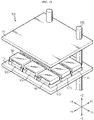
- FIGS. 12 to 14 are diagrams schematically showing an embodiment where a support member 170 is further included in the battery swelling inspection apparatus according to an embodiment of the present disclosure.
- FIGS. 12 and 13 are diagrams schematically showing only one pressure measuring element 140, one pressing member 150, the elastic member 160 and support member 170 in the battery swelling inspection apparatus 100.
- FIG. 12 shows an embodiment in which two leg portions 152 are provided in the pressing member 150 and two support members 170 are provided.
- FIG. 13 shows an embodiment in which four leg portions 152 are provided in the pressing member 150 and four support members 170 are provided.
- FIG. 14 is a diagram showing an embodiment of the battery swelling inspection apparatus 100 in which two leg portions 152 are provided in each of the plurality of pressing members 150 and each leg portion 152 is inserted into the support member 170.
- the battery swelling inspection apparatus 100 may further include a support member 170.
- One end of the support member 170 may be attached to the lower plate 110, and a hollow or a groove may be formed in the support member 170 so that the leg portion 152 is inserted therein.
- leg portion 152 Since the leg portion 152 is inserted into the support member 170 and the leg portion 152 may only move inside the support member 170, even if the body portion 151 of the pressing member 150 rotates, it is possible to prevent the adjacent leg portions 152 from contacting each other.
- the battery swelling inspection apparatus 100 further includes the support member 170, the interval of the plurality of pressure measuring elements 140 disposed on the lower plate 110 (specifically, the interval between the plurality of pressing members 150) may be set narrower. Accordingly, the number of pressure measuring elements 140 that may be disposed on the lower plate 110 may be increased, and thus the swelling distribution and/or the swelling degree of the battery cell 10 may be more accurately inspected.
- the elastic member 160 may be configured to be located inside the hollow or the groove.
- the hollow may be formed inside the support member 170.
- the elastic member 160 may be provided inside the hollow of the support member 170 so that one end thereof is attached to the upper surface (a surface in +z direction) of the lower plate 110 and the other end thereof is attached to the lower surface (a surface in -z direction) of the leg portion 152 inserted into the hollow.
- the groove may be formed inside the support member 170.
- the elastic member 160 may be seated in the groove of the support member 170 so that one end thereof is attached to the upper surface (a surface in +z direction) of the groove of the support member 170 and the other end thereof is attached to the lower surface (a surface in -z direction) of the leg portion 152 inserted into the groove.
- the battery swelling inspection apparatus 100 since the battery swelling inspection apparatus 100 according to an embodiment of the present disclosure further includes the support member 170 for preventing the adjacent pressing members 150 from contacting, it is possible to improve the accuracy of the swelling pressure measured by each of the plurality of pressure measuring elements 140.
- the battery swelling inspection apparatus 100 includes the elastic member 160 inside the support member 170, the body portion 151 of the pressing member 150 may be more easily returned to its original position after being rotated.
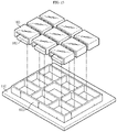
- FIGS. 15 and 16 are diagrams schematically showing an embodiment where a guide member 180 is further included in the battery swelling inspection apparatus 100 according to an embodiment of the present disclosure.
- the battery swelling inspection apparatus 100 may further include a guide member 180.
- the guide member 180 may be configured to protrude in an upper direction (+z direction) from the upper surface of the lower plate 110 so as to divide the upper surface (the surface in +z direction) of the lower plate 110 into a plurality of sections.
- the guide member 180 may be configured integrally with the lower plate 110 or may be configured separately from the lower plate 110 and attached to the lower plate 110.
- FIGS. 15 and 16 show an embodiment in which the guide member 180 and the lower plate 110 may be configured individually and the guide member 180 may be attached to the lower plate 110.
- the upper surface of the lower plate 110 may be divided into a plurality of sections by the guide member 180.
- the pressure measuring element 140 and the pressing member 150 may be provided in each section.
- at least one of the elastic member 160 and the support member 170 may be further provided in each section.
- the battery swelling inspection apparatus 100 further includes the guide member 180, it is possible to prevent the plurality of pressing members 150 from contacting in advance.
- the deformation force of the elastic member 160 may exceed an elastic limit. That is, if the body portion 151 of the pressing member 150 is excessively rotated, some of the elastic members 160 may expand to exceed the elastic limit. In this case, the elastic member 160 expanded to exceed the elastic limit may undergo plastic deformation. Therefore, there is a problem in that the swelling distribution and/or the swelling degree of the battery cell 10 may no longer be accurately measured using the elastic member 160.
- the upper surface of the pressing member 150 may protrude by a predetermined length L2 from the upper surface of the guide member 180.
- the volume of the battery cell 10 may increase to press the pressing member 150.
- a swelling pressure may be applied to the pressing member 150 as much as the increased volume of the battery cell 10.
- the height L1 of the guide member 180 may be determined in consideration of the elastic limit of the elastic member 160.
- the guide member 180 prevents the volume of the battery cell 10 from increasing above a certain level, it is possible to prevent the pressing member 150 from being excessively rotated in one direction and expanding the elastic member 160 to exceed the elastic limit.
- the height of the guide member 180 may be determined in consideration of the elastic limit of the elastic member 160 and the height (L1 + L2) from the upper surface of the lower plate 110 to the upper surface of the pressing member 150.
- the height of the guide member 180 may be determined in comprehensive consideration of the elastic limit of the elastic member 160, the height (L1 + L2) from the upper surface of the lower plate 110 to the upper surface of the pressing member 150, and the maximum degree of expansion of the battery cell 10.
- the battery swelling inspection apparatus 100 has an advantage of preventing damage to the elastic member 160, thereby reducing maintenance and repair costs of the inspection apparatus.
- the battery swelling inspection apparatus 100 has an advantage of more accurately inspecting the swelling distribution and/or the swelling degree of the battery cell 10, since the possibility of damage to the elastic member 160 may be dramatically reduced.
- the battery swelling inspection apparatus 100 may further include a control unit 190.
- control unit 190 may selectively include processors known in the art, application-specific integrated circuit (ASIC), other chipsets, logic circuits, registers, communication modems, data processing devices, and the like to execute various control logic performed in the present disclosure.
- ASIC application-specific integrated circuit
- the control unit 190 may be implemented as a set of program modules.
- the program module may be stored in a memory and executed by the control unit 190.
- the memory may be located inside or out of the control unit 190 and may be connected to the control unit 190 by various well-known means.
- the control unit 190 is connected to the plurality of pressure measuring elements 140 and may be configured to receive a measured pressure value from each of the plurality of pressure measuring elements 140.
- control unit 190 may be communicatively connected to the plurality of pressure measuring elements 140 through wired communication.
- control unit 190 may receive the measured pressure value from the plurality of pressure measuring elements 140. That is, the control unit 190 may receive the swelling pressure value of the battery cell 10 measured by each of the plurality of pressure measuring elements 140.
- control unit 190 may be configured to determine at least one of the swelling distribution of the battery cell 10 and the swelling degree of each region of the battery cell 10 based on the plurality of received pressure values.
- the first pressure measuring element 140a may measure the pressure value of the first region of the battery cell 10.
- the second pressure measuring element 140b may measure the pressure value of the second region of the battery cell 10
- the third pressure measuring element 140c may measure the pressure value of the third region of the battery cell 10.
- the control unit 190 may receive a first pressure value from the first pressure measuring element 140a. In addition, the control unit 190 may receive a second pressure value from the second pressure measuring element 140b and receive a third pressure value from the third pressure measuring element 140c.
- the control unit 190 may determine a swelling distribution for the first region, the second region and the third region of the battery cell 10 based on the first pressure value, the second pressure value and the third pressure value, respectively.
- control unit 190 may calculate a first pressure difference value between the first pressure value and a reference pressure value, calculate a second pressure difference value between the second pressure value and the reference pressure value, and calculate a third pressure difference value between the third pressure value and the reference pressure value.
- the control unit 190 may determine the swelling degree for each of the first region, the second region and the third region of the battery cell 10 by matching the first pressure difference value, the second pressure difference value and the third pressure difference value with a plurality of preset pressure sections.
- the plurality of pressure sections may be set in advance as a normal section, a warning section and a danger section.
- the plurality of pressure sections may be stored in an internal memory of the control unit 190 or an external memory.
- the control unit 190 may determine that the swelling degree of the first region of the battery cell 10 is the danger level, the swelling degree of the second region is the warning level, and the swelling degree of the third region is the normal level.
- control unit 190 may be configured to determine the swelling distribution of each region of the battery cell 10 first and then determine the swelling degree of only the region of the battery cell 10 that is determined to have swelling.
- control unit 190 determines that swelling occurs in the first region and the second region of the battery cell 10.
- the control unit 190 may determine the swelling degree for the first region by matching the first pressure difference value for the first region of the battery cell 10 with the plurality of preset pressure sections.
- control unit 190 may determine the swelling degree for the second region of the battery cell 10 by matching the second pressure difference value for the second region of the battery cell 10 with the plurality of preset pressure sections.
- the control unit 190 may compare the sizes of the plurality of received pressure values and the reference pressure value, and determine that swelling occurs if the received pressure value is greater than or equal to the reference pressure value.
- the battery swelling inspection apparatus 100 may determine the swelling distribution of the battery cell 10 and/or the swelling degree of each region of the battery cell 10. Accordingly, a region in which swelling occurs in the battery cell 10 may be specifically specified.
- the battery swelling inspection apparatus 100 may specifically determine the swelling degree of each region of the battery cell 10, there is an advantage of providing information for analyzing the cause of the swelling of the battery cell 10.
- the swelling distribution of the battery cell 10 and the swelling degree of each region obtained from the battery swelling inspection apparatus 100 it is possible to distinguish whether the swelling is caused by an increase in pressure due to gas generation or an increase in pressure due to inflow of foreign substances.
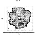
- FIG. 17 is a diagram schematically showing a swelling inspection result of a battery cell 10 using the battery swelling inspection apparatus 100 according to an embodiment of the present disclosure.
- the degree of swelling is most severe in a region in the -y direction among regions (A to I) of the battery cell 10 divided into nine. That is, in the embodiment of FIG. 7 , it may be seen that swelling occurs most severely in the region H of the battery cell 10 corresponding to the second pressure measuring element 140b among three pressure measuring elements 140 located in the -y direction.
- the battery swelling inspection apparatus 100 may check a region of the battery cell 10 where swelling occurs most severely by using the swelling distribution of each region of the battery cell 10.
- the embodiments of the present disclosure described above may not be implemented only through an apparatus and a method, but may be implemented through a program that realizes a function corresponding to the configuration of the embodiments of the present disclosure or a recording medium on which the program is recorded.
- the program or recording medium may be easily implemented by those skilled in the art from the above description of the embodiments.
Landscapes
- Chemical & Material Sciences (AREA)
- Chemical Kinetics & Catalysis (AREA)
- Electrochemistry (AREA)
- General Chemical & Material Sciences (AREA)
- Engineering & Computer Science (AREA)
- Manufacturing & Machinery (AREA)
- Physics & Mathematics (AREA)
- General Physics & Mathematics (AREA)
- Battery Mounting, Suspending (AREA)
- Secondary Cells (AREA)
Abstract
Description
- The present application claims priority to
Korean Patent Application No. 10-2020-0034628 filed on March 20, 2020 - The present disclosure relates to a battery swelling inspection apparatus, and more particularly, to a battery swelling inspection apparatus capable of inspecting swelling of a battery cell.
- Recently, the demand for portable electronic products such as notebook computers, video cameras and portable telephones has increased sharply, and electric vehicles, energy storage batteries, robots, satellites and the like have been developed in earnest. Accordingly, high-performance batteries allowing repeated charging and discharging are being actively studied.
- Batteries commercially available at present include nickel-cadmium batteries, nickel hydrogen batteries, nickel-zinc batteries, lithium batteries and the like. Among them, the lithium batteries are in the limelight since they have almost no memory effect compared to nickel-based batteries and also have very low self-charging rate and high energy density.
- Such a battery may cause swelling in which gas is generated in the battery during charging and discharging or in a high temperature state to inflate the battery. Since there is a risk of fire or explosion due to battery swelling, it is important to accurately inspect the swelling behavior of the battery.
- Conventionally, a device for inspecting swelling of a battery using a plurality of load cells has been disclosed (Patent Document 1). Referring to Patent Document 1, a first plate, a plurality of load cells, a second plate, a measurement target (a battery cell) and a third plate are stacked, and the first plate, the second plate and the third plate are fixed using a plurality of fastening members. In particular, since the second plate provided between the battery cell and the plurality of load cells is fixed by the fastening member, the swelling pressure of each region of the battery cell transmitted to the plurality of load cells is inevitably lost seriously. That is, in Patent Document 1, since the movement of the second plate caused by the swelling pressure is restricted by the fastening member, there is a limitation in that the swelling of the battery cell may not be accurately inspected.
- In addition, referring to
FIG. 9 of Patent Document 1, a structure in which the second plate is composed of a plurality of partial flat plates and the partial flat plates are connected to each other by a connection unit is disclosed. Since the partial flat plates are connected to each other, there is a problem that the swelling pressure applied to one of the partial flat plates may affect the other partial flat plates. - In addition, the plurality of partial flat plates of Patent Document 1 are restricted to each other by the connecting unit made of a material having elasticity or ductility. That is, if a swelling pressure is applied to any one partial flat plate, the swelling pressure is not transmitted only to the load cell located in a lower direction, but is distributed through the connection unit.
- Considering the above, there is a problem that the pressure of the battery cell measured by the battery cell pressure measuring device disclosed in Patent Document 1 may be inaccurate.
- (Patent Document 1)
KR 10-2017-0042082 A - The present disclosure is designed to solve the problems of the related art, and therefore the present disclosure is directed to providing a battery swelling inspection apparatus capable of independently measuring the pressure of each region of a battery cell corresponding to each of a plurality of pressure measuring elements.
- These and other objects and advantages of the present disclosure may be understood from the following detailed description and will become more fully apparent from the exemplary embodiments of the present disclosure. Also, it will be easily understood that the objects and advantages of the present disclosure may be realized by the means shown in the appended claims and combinations thereof.
- In one aspect of the present disclosure, there is provided a battery swelling inspection apparatus, comprising: a lower plate configured in a plate shape; an upper plate configured in a plate shape and located to face the lower plate; a fixing frame configured such that a portion of the lower plate and a portion of the upper plate are fixedly coupled thereto; a plurality of pressure measuring elements fixedly coupled to the lower plate, having a head located to face the upper plate, and configured to measure a pressure applied to the head, respectively; and a plurality of pressing members configured to have an upper surface in a flat shape so that the upper surface faces the upper plate and have a lower surface that is at least partially attached to the head of each of the plurality of pressure measuring elements.
- The pressure measuring element may be configured such that at least a portion of the head is inclined.
- The pressure measuring element may be configured such that at least a portion of the head has a curved surface.
- The pressing member may be configured such that a center portion of the lower surface thereof is attached to the head.
- The pressing member may be configured such that the upper surface thereof faces the upper plate at a predetermined interval.
- The fixing frame may be configured such that the interval between the upper surface of the pressing member and the upper plate is adjustable.
- The pressing member may include: a body portion configured in a plate shape having the upper surface and the lower surface; and a leg portion configured to protrude in a lower direction from at least a portion of the body portion.
- The pressing member may be configured such that an angle between the body portion and the leg portion is changeable.
- The leg portion may be coupled with at least a portion of the body portion and configured to enable hinge rotation thereat.
- A battery swelling inspection apparatus according to another aspect of the present disclosure may further comprise an elastic member configured to have one end attached to the lower plate and the other end attached to the leg portion.
- The body portion may be configured to be inclinable based on the head to correspond to a location where a pressure is applied.
- The leg portion may be configured to be movable in an upper direction or in a lower direction by the elastic member that contracts or expands depending on the degree of inclination of the body portion.
- A battery swelling inspection apparatus according to still another aspect of the present disclosure may further comprise a support member configured to have one end attached to the lower plate and have a hollow or a groove so that the leg portion is inserted therein.
- The elastic member may be configured to be located in the hollow or the groove.
- A battery swelling inspection apparatus according to still another aspect of the present disclosure may further comprise a guide member configured to protrude in an upper direction from an upper surface of the lower plate so that the upper surface of the lower plate is divided into a plurality of sections.
- A battery swelling inspection apparatus according to still another aspect of the present disclosure may further comprise a control unit connected to the plurality of pressure measuring elements and configured to receive a measured pressure value from each of the plurality of pressure measuring elements and, when a battery cell is interposed between the upper plate and the pressing member, determine at least one of a swelling distribution of the battery cell and a swelling degree of each region of the battery cell based on the plurality of received pressure values.
- According to an aspect of the present disclosure, there is an advantage that the swelling distribution of the battery cell and/or the swelling degree of each region of the battery cell may be more accurately measured.
- The effects of the present disclosure are not limited to the effects mentioned above, and other effects not mentioned will be clearly understood by those skilled in the art from the description of the claims.
- The accompanying drawings illustrate a preferred embodiment of the present disclosure and together with the foregoing disclosure, serve to provide further understanding of the technical features of the present disclosure, and thus, the present disclosure is not construed as being limited to the drawing.
-
FIG. 1 is a block diagram schematically showing a battery swelling inspection apparatus according to an embodiment of the present disclosure.FIG. 2 is a diagram schematically showing the battery swelling inspection apparatus according to an embodiment of the present disclosure. -
FIG. 3 is a diagram showing a pressure measuring element of the battery swelling inspection apparatus according to an embodiment of the present disclosure. -
FIG. 4 is an exploded perspective view showing a pressure measuring element and a pressing member, in the battery swelling inspection apparatus according to an embodiment of the present disclosure. -
FIG. 5 is an assembled perspective view showing the pressure measuring element and the pressing member, in the battery swelling inspection apparatus according to an embodiment of the present disclosure. -
FIG. 6 is a diagram showing another embodiment of the pressing member, in the battery swelling inspection apparatus according to an embodiment of the present disclosure. -
FIG. 7 is a diagram schematically showing the battery swelling inspection apparatus according to an embodiment of the present disclosure. -
FIG. 8 is a diagram showing another embodiment of the pressing member, in the battery swelling inspection apparatus according to an embodiment of the present disclosure. -
FIG. 9 is a diagram more specifically showing the pressing member, in the battery swelling inspection apparatus according to an embodiment of the present disclosure. -
FIG. 10 is a diagram showing an embodiment in which the pressing member is inclined, in the battery swelling inspection apparatus according to an embodiment of the present disclosure. -
FIG. 11 is a diagram schematically showing an embodiment where an elastic member is further included in the battery swelling inspection apparatus according to an embodiment of the present disclosure. -
FIGS. 12 to 14 are diagrams schematically showing an embodiment where a support member is further included in the battery swelling inspection apparatus according to an embodiment of the present disclosure. -
FIGS. 15 and16 are diagrams schematically showing an embodiment where a guide member is further included in the battery swelling inspection apparatus according to an embodiment of the present disclosure. -
FIG. 17 is a diagram schematically showing a swelling inspection result of a battery cell using the battery swelling inspection apparatus according to an embodiment of the present disclosure. - It should be understood that the terms used in the specification and the appended claims should not be construed as limited to general and dictionary meanings, but interpreted based on the meanings and concepts corresponding to technical aspects of the present disclosure on the basis of the principle that the inventor is allowed to define terms appropriately for the best explanation.
- Therefore, the description proposed herein is just a preferable example for the purpose of illustrations only, not intended to limit the scope of the disclosure, so it should be understood that other equivalents and modifications could be made thereto without departing from the scope of the disclosure.
- Additionally, in describing the present disclosure, when it is deemed that a detailed description of relevant known elements or functions renders the key subject matter of the present disclosure ambiguous, the detailed description is omitted herein.
- The terms including the ordinal number such as "first", "second" and the like, may be used to distinguish one element from another among various elements, but not intended to limit the elements by the terms.
- Throughout the specification, when a portion is referred to as "comprising" or "including" any element, it means that the portion may include other elements further, without excluding other elements, unless specifically stated otherwise.
- Furthermore, the term "control unit" described in the specification refers to a unit that processes at least one function or operation, and may be implemented by hardware, software, or a combination of hardware and software.
- In addition, throughout the specification, when a portion is referred to as being "connected" to another portion, it is not limited to the case that they are "directly connected", but it also includes the case where they are "indirectly connected" with another element being interposed between them.
- Hereinafter, preferred embodiments of the present disclosure will be described in detail with reference to the accompanying drawings.
-
FIG. 1 is a block diagram schematically showing a batteryswelling inspection apparatus 100 according to an embodiment of the present disclosure.FIG. 2 is a diagram schematically showing the batteryswelling inspection apparatus 100 according to an embodiment of the present disclosure. - The battery
swelling inspection apparatus 100 according to an embodiment of the present disclosure is a device for inspecting swelling of abattery cell 10, and may inspect a swelling distribution and/or a swelling degree. - Here, the
battery cell 10 refers to one independent cell that has a negative electrode terminal and a positive electrode terminal and is physically separable. For example, one pouch-type lithium polymer cell may be regarded as a battery cell. - In general, battery swelling, in which the
battery cell 10 is inflated, may occur not only at a center portion of thebattery cell 10 but also at a peripheral portion thereof. Here, the peripheral portion refers to an area excluding the center portion. Accordingly, the batteryswelling inspection apparatus 100 may inspect a pressure distribution (a swelling distribution) of thebattery cell 10 caused by swelling and/or a pressure level (a swelling degree) of each region of thebattery cell 10 caused by swelling. - Referring to
FIGS. 1 and 2 , the batteryswelling inspection apparatus 100 according to an embodiment of the present disclosure may include alower plate 110, anupper plate 120, a fixingframe 130, apressure measuring element 140, and apressing member 150. - The
lower plate 110 may be configured in a plate shape. - Specifically, the
lower plate 110 may be configured in a plate shape so that a plurality ofpressure measuring elements 140 may be attached thereto. For example, in the embodiment ofFIG. 2 , thelower plate 110 may be configured in a flat plate shape. - The
upper plate 120 may be configured in a plate shape and located to face thelower plate 110. - Specifically, the
upper plate 120 may be configured in a flat plate shape so that a lower surface of theupper plate 120 contacts an upper surface of thebattery cell 10. - Preferably, the
upper plate 120 and thebattery cell 10 may be attached and detached. For example, when swelling of thebattery cell 10 is inspected, the upper surface of thebattery cell 10 may be attached to the lower surface ofupper plate 120. In addition, if the inspection of swelling of thebattery cell 10 is finished, thebattery cell 10 may be detached from theupper plate 120. - In addition, since the
battery cell 10 is interposed between theupper plate 120 and thelower plate 110, theupper plate 120 and thelower plate 110 may be located to face each other. - For example, in the embodiment of
FIG. 2 , theupper plate 120 and thelower plate 110 are located to face each other, and thebattery cell 10 may be provided between theupper plate 120 and thelower plate 110. - The fixing
frame 130 may be configured such that a portion of thelower plate 110 and a portion of theupper plate 120 are fixedly coupled thereto. - Specifically, the fixing
frame 130 may fix theupper plate 120 and thelower plate 110 so that theupper plate 120 and thelower plate 110 are not shaken or rotated. - The
pressure measuring element 140 may be provided in plural. In addition, the plurality ofpressure measuring elements 140 may be fixedly coupled to thelower plate 110. - Here, the number of the
pressure measuring elements 140 included in the batteryswelling inspection apparatus 100 is not limited. However, if a larger number ofpressure measuring elements 140 are provided, the accuracy of the swelling inspection may be improved. Hereinafter, for convenience of description, it will be described that ninepressure measuring elements 140 are provided. - In addition, the plurality of
pressure measuring elements 140 may be fixedly coupled to thelower plate 110 to be spaced apart from each other at a constant interval. - For example, if the plurality of
pressure measuring elements 140 are biased and fixedly coupled to a portion of thelower plate 110, the swelling distribution of thebattery cell 10 may not be accurately measured. Accordingly, the plurality ofpressure measuring elements 140 may be disposed on thelower plate 110 at predetermined intervals. - The
pressure measuring element 140 may be located so that ahead 141 thereof faces theupper plate 120 and may be configured to measure a pressure applied to thehead 141, respectively. -
FIG. 3 is a diagram showing thepressure measuring element 140 of the batteryswelling inspection apparatus 100 according to an embodiment of the present disclosure. - Referring to
FIG. 3 , thepressure measuring element 140 may include ahead 141 and abody 142. In addition, thepressure measuring element 140 may be configured to measure a pressure applied to thehead 141. For example, a load cell may be applied as thepressure measuring element 140. - Specifically, if swelling occurs in the
battery cell 10, a swelling pressure may be applied to thehead 141 of each of the plurality ofpressure measuring elements 140. Each of the plurality ofpressure measuring elements 140 may measure the swelling pressure applied to thehead 141. In this case, since the plurality ofpressure measuring elements 140 do not affect each other during the process of measuring pressure, the swelling pressures measured by the plurality ofpressure measuring elements 140 differs from each other according to locations where swelling occurs in thebattery cell 10. - The pressing
member 150 may be provided in plural. Preferably, the number of thepressing members 150 may correspond to the number of the plurality ofpressure measuring elements 140. - The pressing
member 150 may be configured such that an upper surface thereof is formed in a flat shape and the upper surface thereof faces theupper plate 120. - Specifically, the
battery cell 10 may be interposed between thepressing member 150 and theupper plate 120. The upper surface of thepressing member 150 may be formed in a flat shape so that the swelling pressure of thebattery cell 10 may be applied to thepressing member 150 when the upper surface of thepressing member 150 contacts thebattery cell 10. - For example, in the embodiment of
FIG. 2 , thebattery cell 10 may be interposed and fixed between the upper surface of thepressing member 150 and theupper plate 120. - The pressing
member 150 may be configured such that at least a portion of the lower surface thereof is attached to thehead 141 of each of the plurality ofpressure measuring elements 140. - For example, the
head 141 of thepressure measuring element 140 and thepressing member 150 may be made of magnetic materials that may be attached to each other. More preferably, an upper end of thehead 141 of thepressure measuring element 140 and a center portion of the lower surface of thepressing member 150 may be made of magnetic materials. Accordingly, by magnetism, the center portion of the lower surface of thepressing member 150 may be attached to the upper end of thehead 141 of thepressure measuring element 140. In addition, the pressingmember 150 may be attached to and detached from thehead 141 of thepressure measuring element 140. -
FIG. 4 is an exploded perspective view showing thepressure measuring element 140 and thepressing member 150, in the batteryswelling inspection apparatus 100 according to an embodiment of the present disclosure.FIG. 5 is an assembled perspective view showing thepressure measuring element 140 and thepressing member 150, in the batteryswelling inspection apparatus 100 according to an embodiment of the present disclosure. - Referring to
FIGS. 4 and5 , the plurality of pressingmembers 150 may be attached to the correspondingpressure measuring elements 140. That is, the plurality of pressingmembers 150 and the plurality ofpressure measuring elements 140 may correspond to each other in one-to-one relationship. - For example, the center portion of the lower surface (a surface in -z direction) of the
pressing member 150 may be attached to the upper end (the upper end in the +z direction) of thehead 141. Preferably, the pressingmember 150 may be attached to thehead 141 of thepressure measuring element 140 such that the upper surface (a surface in +z direction) thereof is parallel to thelower plate 110. - In addition, referring to
FIG. 5 , the plurality of pressingmembers 150 may be spaced apart from each other by a predetermined distance. - For example, it is assumed that a first pressing
member 150 corresponds to a firstpressure measuring element 140a and a secondpressing member 150 corresponds to a secondpressure measuring element 140b. If the swelling pressure of the battery is applied to the first pressingmember 150, the first pressingmember 150 may transmit the swelling pressure to thehead 141 of the firstpressure measuring element 140a. That is, pressure in a lower direction (-z direction) is applied to the first pressingmember 150 by the swelling pressure, and the swelling pressure may be transmitted to thehead 141 of the firstpressure measuring element 140a through the first pressingmember 150. Since the first pressingmember 150 and the second pressingmember 150 are separated by a predetermined distance and do not contact each other, the swelling pressure applied to the first pressingmember 150 may not have a direct effect on the second pressingmember 150. - The
pressure measuring element 140 may be configured such that at least a portion of thehead 141 is inclined. - Specifically, if a swelling pressure is applied to the
pressing member 150, the pressingmember 150 may be pressed by the applied swelling pressure. In addition, the pressingmember 150 may be inclined to correspond to the location where the swelling pressure is applied. - For example, if the swelling pressure is applied at a location outside the center portion of the
pressing member 150, the pressingmember 150 may be inclined based on the upper end of thehead 141. That is, the center portion of the lower surface of the pressing member 150 (the portion attached to the upper end of the head 141) may act as a supporting point. - Referring to
FIG. 5 , thebody 142 of thepressure measuring element 140 is fixedly coupled to thelower plate 110, and thehead 141 of thepressure measuring element 140 is movable in a vertical direction. For example, inFIG. 5 , thehead 141 may move in an upper direction (+z direction) and a lower direction (-z direction). Therefore, as in the previous example, a portion of the upper end of the head 141 (the upper end in the +z direction) of thepressure measuring element 140 to which thepressing member 150 is attached may be configured in an inclined shape so that the force applied to thepressing member 150 may be transmitted to thehead 141 of thepressure measuring element 140 in a better way while thepressing member 150 is being inclined. - For example, at least a portion of the
head 141 of thepressure measuring element 140 may have an angular shape or a curved shape. Preferably, in thepressure measuring element 140, at least a portion of thehead 141 may be configured to have a curved surface. - Therefore, when the
pressing member 150 is inclined as the swelling pressure is applied to thepressing member 150, it is possible to minimize that the movement of thepressing member 150 is restricted by the shape of thehead 141 of thepressure measuring element 140. That is, since thehead 141 of thepressure measuring element 140 is configured such that thepressing member 150 may be easily inclined, the pressingmember 150 may be easily inclined in response to the applied pressure. - In addition, since the
body portion 151 of thepressing member 150 and the upper end of thehead 141 of thepressure measuring element 140 are made of magnetic materials, the pressingmember 150 may be configured to easily return to its original shape after being inclined. -
FIG. 6 is a diagram showing another embodiment of thepressing member 150, in the batteryswelling inspection apparatus 100 according to an embodiment of the present disclosure. - Referring to
FIG. 6 , a groove corresponding to thehead 141 of thepressure measuring element 140 may be provided in the center portion of the lower surface of thepressing member 150. Preferably, the curvature of the groove in the lower surface of thepressing member 150 may be less than or equal to the curvature of the upper end of thehead 141 of thepressure measuring element 140. - For example, the groove of the lower surface of the
pressing member 150 and the upper end of thehead 141 of thepressure measuring element 140 may be magnetically attached to each other. In addition, if the swelling pressure is applied to thepressing member 150, the pressingmember 150 may be easily inclined along thehead 141 of thepressure measuring element 140. -
FIG. 7 is a diagram schematically showing the battery swelling inspection apparatus according 100 to an embodiment of the present disclosure. - Referring to
FIG. 7 , the pressingmember 150 may be configured such that the upper surface thereof faces theupper plate 120 at a predetermined interval. - To this end, the fixing
frame 130 may be configured to adjust the interval between the upper surface of the pressing member and theupper plate 120. - Specifically, the fixing
frame 130 may be configured to adjust a location where thelower plate 110 and theupper plate 120 are coupled. Preferably, the location in the fixingframe 130 at which thelower plate 110 and theupper plate 120 are fixedly coupled may be adjusted so that thebattery cell 10 may be fixed between thepressing member 150 and theupper plate 120. Accordingly, the interval between the upper surface of thepressing member 150 and the lower surface of theupper plate 120 may be adjusted. - For example, in the embodiment of
FIG. 7 , the fixingframe 130 may be configured to adjust the position where which thelower plate 110 and theupper plate 120 are fixed in a vertical direction (z direction). - If the interval between the upper surface of the
pressing member 150 and the lower surface of theupper plate 120 is not adjustable, there is a problem that the type of thebattery cell 10 to be inspected is limited. - Therefore, since the battery
swelling inspection apparatus 100 according to an embodiment of the present disclosure includes the fixingframe 130 configured to adjust the interval between thelower plate 110 and theupper plate 120, and there is an advantage in that swelling ofbattery cells 10 having various thicknesses (for example, z-direction length of thebattery cell 10 inFIG. 7 ) may be inspected. -
FIG. 8 is a diagram showing another embodiment of thepressing member 150, in the batteryswelling inspection apparatus 100 according to an embodiment of the present disclosure. - The pressing
member 150 may include abody portion 151 and aleg portion 152. - The
body portion 151 may be configured in a plate shape having the upper surface and the lower surface. In addition, theleg portion 152 may be configured to protrude in a lower direction from at least a portion of thebody portion 151. - For example, in the embodiment of
FIG. 8 , thebody portion 151 may be configured in a plate shape having an upper surface (a surface in +z direction) and a lower surface (a surface in -z direction). In addition, theleg portion 152 may protrude in a lower direction (-z direction) from a portion of thebody portion 151. - For example, if the inclined pressing
member 150 and thepressing member 150 adjacent thereto contact each other, the swelling pressure of thebattery cell 10 may not be accurately transmitted to thepressure measuring element 140 corresponding to the inclined pressingmember 150. In this case, the accuracy of the swelling distribution of thebattery cell 10 inspected by the plurality ofpressure measuring elements 140 may be lowered. Accordingly, the plurality ofpressure measuring elements 140 may be disposed on thelower plate 110 with a predetermined interval therebetween so that anyone pressing member 150 does not contact the adjacent pressingmember 150 even though rotating. - Preferably, the pressing
member 150 may be configured such that an angle between thebody portion 151 and theleg portion 152 is changeable. -
FIG. 9 is a diagram more specifically showing thepressing member 150, in the batteryswelling inspection apparatus 100 according to an embodiment of the present disclosure.FIG. 10 is a diagram showing an embodiment in which thepressing member 150 is inclined, in the batteryswelling inspection apparatus 100 according to an embodiment of the present disclosure. - Specifically,
FIG. 9 is an embodiment in which thepressing member 150 is not inclined, andFIG. 10 is an embodiment in which thepressing member 150 is inclined by the swelling pressure F. - Referring to
FIG. 9 , before thepressing member 150 is inclined, the angles between thebody portion 151 and theleg portions 152 may be A1° and B1°. In addition, referring toFIG. 10 , if the swelling pressure F is applied to thepressing member 150 so that thepressing member 150 is rotated, the angles between thebody portion 151 and theleg portions 152 may be changed to A2° and B2°. - Specifically, the
leg portion 152 may be coupled to at least a portion of thebody portion 151 and configured to enable hinge rotation at the coupled point. - That is, the
leg portion 152 and thebody portion 151 may be coupled to each other through ahinge pin 153. In addition, theleg portion 152 and thebody portion 151 may be rotatably coupled based on thehinge pin 153 as an axis. Thus, even if thebody portion 151 of thepressing member 150 is inclined, theleg portion 152 may face the lower direction (-z direction). - Referring to
FIG. 7 again, since theleg portion 152 and thebody portion 151 are configured to enable hinge rotation, even if thebody portions 151 of some of the plurality of pressingmembers 150 are inclined, theleg portions 152 of the plurality of pressingmembers 150 may not contact each other. That is, since theleg portion 152 of thepressing member 150 may always face the lower direction (-z direction), the intervals of the plurality of pressing members disposed on thelower plate 110 may be set narrower. - Therefore, the battery
swelling inspection apparatus 100 according to an embodiment of the present disclosure may more accurately inspect the swelling distribution and/or the swelling degree of thebattery cell 10 by arranging a larger number of pressurizing members on thelower plate 110. -
FIG. 11 is a diagram schematically showing an embodiment where anelastic member 160 is further included in the batteryswelling inspection apparatus 100 according to an embodiment of the present disclosure. Specifically,FIG. 11 is a diagram schematically showing only onepressure measuring element 140, one pressingmember 150 and oneelastic member 160 in the batteryswelling inspection apparatus 100. However, it should be noted that the structure ofFIG. 11 may also be applied to the embodiment ofFIG. 7 . - Referring to
FIG. 11 , the batteryswelling inspection apparatus 100 according to an embodiment of the present disclosure may further include anelastic member 160. - The
elastic member 160 may be configured to have one end attached to thelower plate 110 and the other end attached to theleg portion 152. - More specifically, the
body portion 151 may be configured to be inclined based on thehead 141 to correspond to a location where the pressure is applied. That is, thebody portion 151 may be rotated based on thehead 141 so as to correspond to a location where the pressure is applied. - In addition, the
leg portion 152 is configured to be movable in the upper direction (+z direction) or the lower direction (-z direction) by theelastic member 160 that contracts or expands depending on the degree of inclination of thebody portion 151. - For example, if the
pressing member 150 remains inclined as in the embodiment ofFIG. 10 even after the swelling pressure is temporarily applied, the swelling pressure applied thereafter may not be accurately transmitted to thepressure measuring element 140 through thepressing member 150. - Meanwhile, referring to
FIG. 11 , if the swelling pressure is applied to thepressing member 150 so that thebody portion 151 is inclined, theelastic member 160 may contract or expand accordingly. In addition, if the swelling pressure disappears, the pressingmember 150 inclined by the elastic force of theelastic member 160 may be easily returned to its original position. - Therefore, since the battery
swelling inspection apparatus 100 further includes theelastic member 160 that connects thelower plate 110 and thepressing member 150, when the swelling pressure applied to thepressing member 150 disappears, the pressingmember 150 may be easily returned to its original state. Through this, during the swelling inspection process in which thebattery cell 10 is charged and discharged several times, the swelling distribution and/or the swelling degree of thebattery cell 10 may be more accurately inspected. -
FIGS. 12 to 14 are diagrams schematically showing an embodiment where asupport member 170 is further included in the battery swelling inspection apparatus according to an embodiment of the present disclosure. - Specifically,
FIGS. 12 and 13 are diagrams schematically showing only onepressure measuring element 140, one pressingmember 150, theelastic member 160 andsupport member 170 in the batteryswelling inspection apparatus 100. - More specifically,
FIG. 12 shows an embodiment in which twoleg portions 152 are provided in thepressing member 150 and twosupport members 170 are provided.FIG. 13 shows an embodiment in which fourleg portions 152 are provided in thepressing member 150 and foursupport members 170 are provided. - In addition,
FIG. 14 is a diagram showing an embodiment of the batteryswelling inspection apparatus 100 in which twoleg portions 152 are provided in each of the plurality of pressingmembers 150 and eachleg portion 152 is inserted into thesupport member 170. - Referring to
FIGS. 12 to 14 , the batteryswelling inspection apparatus 100 according to an embodiment of the present disclosure may further include asupport member 170. - One end of the
support member 170 may be attached to thelower plate 110, and a hollow or a groove may be formed in thesupport member 170 so that theleg portion 152 is inserted therein. - Since the
leg portion 152 is inserted into thesupport member 170 and theleg portion 152 may only move inside thesupport member 170, even if thebody portion 151 of thepressing member 150 rotates, it is possible to prevent theadjacent leg portions 152 from contacting each other. - Since the battery
swelling inspection apparatus 100 according to an embodiment of the present disclosure further includes thesupport member 170, the interval of the plurality ofpressure measuring elements 140 disposed on the lower plate 110 (specifically, the interval between the plurality of pressing members 150) may be set narrower. Accordingly, the number ofpressure measuring elements 140 that may be disposed on thelower plate 110 may be increased, and thus the swelling distribution and/or the swelling degree of thebattery cell 10 may be more accurately inspected. - Preferably, the
elastic member 160 may be configured to be located inside the hollow or the groove. - For example, in the embodiment of
FIG. 12 , the hollow may be formed inside thesupport member 170. In addition, theelastic member 160 may be provided inside the hollow of thesupport member 170 so that one end thereof is attached to the upper surface (a surface in +z direction) of thelower plate 110 and the other end thereof is attached to the lower surface (a surface in -z direction) of theleg portion 152 inserted into the hollow. - As another example, the groove may be formed inside the
support member 170. In this case, theelastic member 160 may be seated in the groove of thesupport member 170 so that one end thereof is attached to the upper surface (a surface in +z direction) of the groove of thesupport member 170 and the other end thereof is attached to the lower surface (a surface in -z direction) of theleg portion 152 inserted into the groove. - That is, since the battery
swelling inspection apparatus 100 according to an embodiment of the present disclosure further includes thesupport member 170 for preventing the adjacent pressingmembers 150 from contacting, it is possible to improve the accuracy of the swelling pressure measured by each of the plurality ofpressure measuring elements 140. - In addition, since the battery
swelling inspection apparatus 100 includes theelastic member 160 inside thesupport member 170, thebody portion 151 of thepressing member 150 may be more easily returned to its original position after being rotated. -
FIGS. 15 and16 are diagrams schematically showing an embodiment where aguide member 180 is further included in the batteryswelling inspection apparatus 100 according to an embodiment of the present disclosure. - Referring to
FIGS. 15 and16 , the batteryswelling inspection apparatus 100 according to an embodiment of the present disclosure may further include aguide member 180. - The
guide member 180 may be configured to protrude in an upper direction (+z direction) from the upper surface of thelower plate 110 so as to divide the upper surface (the surface in +z direction) of thelower plate 110 into a plurality of sections. - The
guide member 180 may be configured integrally with thelower plate 110 or may be configured separately from thelower plate 110 and attached to thelower plate 110. For example,FIGS. 15 and16 show an embodiment in which theguide member 180 and thelower plate 110 may be configured individually and theguide member 180 may be attached to thelower plate 110. - Referring to
FIGS. 15 and16 , the upper surface of thelower plate 110 may be divided into a plurality of sections by theguide member 180. In addition, thepressure measuring element 140 and thepressing member 150 may be provided in each section. In addition, referring to various embodiments above, at least one of theelastic member 160 and thesupport member 170 may be further provided in each section. - Since the battery
swelling inspection apparatus 100 according to an embodiment of the present disclosure further includes theguide member 180, it is possible to prevent the plurality of pressingmembers 150 from contacting in advance. - Meanwhile, if the swelling degree of the
battery cell 10 is so severe to change the volume change of thebattery cell 10 greatly, the deformation force of theelastic member 160 may exceed an elastic limit. That is, if thebody portion 151 of thepressing member 150 is excessively rotated, some of theelastic members 160 may expand to exceed the elastic limit. In this case, theelastic member 160 expanded to exceed the elastic limit may undergo plastic deformation. Therefore, there is a problem in that the swelling distribution and/or the swelling degree of thebattery cell 10 may no longer be accurately measured using theelastic member 160. - For example, in the embodiment of
FIG. 16 , the upper surface of thepressing member 150 may protrude by a predetermined length L2 from the upper surface of theguide member 180. In addition, if swelling occurs in thebattery cell 10, the volume of thebattery cell 10 may increase to press the pressingmember 150. Here, since theupper plate 120 and thelower plate 110 are fixed not to be shaken or rotated by the fixingframe 130, a swelling pressure may be applied to thepressing member 150 as much as the increased volume of thebattery cell 10. - In order to prevent this problem in advance, the height L1 of the
guide member 180 may be determined in consideration of the elastic limit of theelastic member 160. - That is, since the
guide member 180 prevents the volume of thebattery cell 10 from increasing above a certain level, it is possible to prevent thepressing member 150 from being excessively rotated in one direction and expanding theelastic member 160 to exceed the elastic limit. - Preferably, the height of the
guide member 180 may be determined in consideration of the elastic limit of theelastic member 160 and the height (L1 + L2) from the upper surface of thelower plate 110 to the upper surface of thepressing member 150. - More preferably, the height of the
guide member 180 may be determined in comprehensive consideration of the elastic limit of theelastic member 160, the height (L1 + L2) from the upper surface of thelower plate 110 to the upper surface of thepressing member 150, and the maximum degree of expansion of thebattery cell 10. - Therefore, the battery
swelling inspection apparatus 100 according to an embodiment of the present disclosure has an advantage of preventing damage to theelastic member 160, thereby reducing maintenance and repair costs of the inspection apparatus. - In addition, the battery
swelling inspection apparatus 100 has an advantage of more accurately inspecting the swelling distribution and/or the swelling degree of thebattery cell 10, since the possibility of damage to theelastic member 160 may be dramatically reduced. - Referring to
FIG. 1 , the batteryswelling inspection apparatus 100 according to an embodiment of the present disclosure may further include acontrol unit 190. - Here, the
control unit 190 may selectively include processors known in the art, application-specific integrated circuit (ASIC), other chipsets, logic circuits, registers, communication modems, data processing devices, and the like to execute various control logic performed in the present disclosure. Also, when the control logic is implemented in software, thecontrol unit 190 may be implemented as a set of program modules. At this time, the program module may be stored in a memory and executed by thecontrol unit 190. The memory may be located inside or out of thecontrol unit 190 and may be connected to thecontrol unit 190 by various well-known means. - The
control unit 190 is connected to the plurality ofpressure measuring elements 140 and may be configured to receive a measured pressure value from each of the plurality ofpressure measuring elements 140. - For example, the
control unit 190 may be communicatively connected to the plurality ofpressure measuring elements 140 through wired communication. In addition, thecontrol unit 190 may receive the measured pressure value from the plurality ofpressure measuring elements 140. That is, thecontrol unit 190 may receive the swelling pressure value of thebattery cell 10 measured by each of the plurality ofpressure measuring elements 140. - In addition, if the
battery cell 10 is interposed between theupper plate 120 and thepressing member 150, thecontrol unit 190 may be configured to determine at least one of the swelling distribution of thebattery cell 10 and the swelling degree of each region of thebattery cell 10 based on the plurality of received pressure values. - For example, in the embodiment of
FIG. 7 , the firstpressure measuring element 140a may measure the pressure value of the first region of thebattery cell 10. In addition, the secondpressure measuring element 140b may measure the pressure value of the second region of thebattery cell 10, and the thirdpressure measuring element 140c may measure the pressure value of the third region of thebattery cell 10. Hereinafter, the present disclosure will be described based on the embodiment ofFIG. 7 , but it should be noted that the following feature may be applied identically to the embodiments ofFIGS. 14 and16 . - The
control unit 190 may receive a first pressure value from the firstpressure measuring element 140a. In addition, thecontrol unit 190 may receive a second pressure value from the secondpressure measuring element 140b and receive a third pressure value from the thirdpressure measuring element 140c. - The
control unit 190 may determine a swelling distribution for the first region, the second region and the third region of thebattery cell 10 based on the first pressure value, the second pressure value and the third pressure value, respectively. - In addition, the
control unit 190 may calculate a first pressure difference value between the first pressure value and a reference pressure value, calculate a second pressure difference value between the second pressure value and the reference pressure value, and calculate a third pressure difference value between the third pressure value and the reference pressure value. - The
control unit 190 may determine the swelling degree for each of the first region, the second region and the third region of thebattery cell 10 by matching the first pressure difference value, the second pressure difference value and the third pressure difference value with a plurality of preset pressure sections. - Here, the plurality of pressure sections may be set in advance as a normal section, a warning section and a danger section. In addition, the plurality of pressure sections may be stored in an internal memory of the
control unit 190 or an external memory. - For example, it is assumed that among the plurality of pressure sections, the first pressure difference value belongs to the danger section, the second pressure difference value belongs to the warning section, and the third pressure difference value belongs to the normal section. The
control unit 190 may determine that the swelling degree of the first region of thebattery cell 10 is the danger level, the swelling degree of the second region is the warning level, and the swelling degree of the third region is the normal level. - More preferably, the
control unit 190 may be configured to determine the swelling distribution of each region of thebattery cell 10 first and then determine the swelling degree of only the region of thebattery cell 10 that is determined to have swelling. - In the former embodiment, it is assumed that the
control unit 190 determines that swelling occurs in the first region and the second region of thebattery cell 10. Thecontrol unit 190 may determine the swelling degree for the first region by matching the first pressure difference value for the first region of thebattery cell 10 with the plurality of preset pressure sections. In addition, thecontrol unit 190 may determine the swelling degree for the second region of thebattery cell 10 by matching the second pressure difference value for the second region of thebattery cell 10 with the plurality of preset pressure sections. Here, thecontrol unit 190 may compare the sizes of the plurality of received pressure values and the reference pressure value, and determine that swelling occurs if the received pressure value is greater than or equal to the reference pressure value. - That is, the battery
swelling inspection apparatus 100 according to another embodiment of the present disclosure may determine the swelling distribution of thebattery cell 10 and/or the swelling degree of each region of thebattery cell 10. Accordingly, a region in which swelling occurs in thebattery cell 10 may be specifically specified. - In addition, since the battery
swelling inspection apparatus 100 may specifically determine the swelling degree of each region of thebattery cell 10, there is an advantage of providing information for analyzing the cause of the swelling of thebattery cell 10. - For example, based on the swelling distribution of the
battery cell 10 and the swelling degree of each region obtained from the batteryswelling inspection apparatus 100, it is possible to distinguish whether the swelling is caused by an increase in pressure due to gas generation or an increase in pressure due to inflow of foreign substances. -
FIG. 17 is a diagram schematically showing a swelling inspection result of abattery cell 10 using the batteryswelling inspection apparatus 100 according to an embodiment of the present disclosure. - Referring to the swelling distribution of the
battery cell 10 illustrated inFIG. 17 , it may be determined that the degree of swelling is most severe in a region in the -y direction among regions (A to I) of thebattery cell 10 divided into nine. That is, in the embodiment ofFIG. 7 , it may be seen that swelling occurs most severely in the region H of thebattery cell 10 corresponding to the secondpressure measuring element 140b among threepressure measuring elements 140 located in the -y direction. - As described above, the battery
swelling inspection apparatus 100 according to an embodiment of the present disclosure may check a region of thebattery cell 10 where swelling occurs most severely by using the swelling distribution of each region of thebattery cell 10. - The embodiments of the present disclosure described above may not be implemented only through an apparatus and a method, but may be implemented through a program that realizes a function corresponding to the configuration of the embodiments of the present disclosure or a recording medium on which the program is recorded. The program or recording medium may be easily implemented by those skilled in the art from the above description of the embodiments.
- The present disclosure has been described in detail. However, it should be understood that the detailed description and specific examples, while indicating preferred embodiments of the disclosure, are given by way of illustration only, since various changes and modifications within the scope of the disclosure will become apparent to those skilled in the art from this detailed description.
- Additionally, many substitutions, modifications and changes may be made to the present disclosure described hereinabove by those skilled in the art without departing from the technical aspects of the present disclosure, and the present disclosure is not limited to the above-described embodiments and the accompanying drawings, and each embodiment may be selectively combined in part or in whole to allow various modifications.
-
- 10: battery cell
- 100: battery swelling inspection apparatus
- 110: lower plate
- 120: upper plate
- 130: fixing frame
- 140: pressure measuring element
- 140a: first pressure measuring element
- 140b: second pressure measuring element
- 140c: third pressure measuring element
- 141: head
- 142: body
- 150: pressing member
- 151: body portion
- 152: leg portion
- 153: hinge pin
- 160: elastic member
- 170: support member
- 180: guide member
- 190: control unit
Claims (15)
- A battery swelling inspection apparatus, comprising:a lower plate configured in a plate shape;an upper plate configured in a plate shape and located to face the lower plate;a fixing frame configured such that a portion of the lower plate and a portion of the upper plate are fixedly coupled thereto;a plurality of pressure measuring elements fixedly coupled to the lower plate, having a head located to face the upper plate, and configured to measure a pressure applied to the head, respectively; anda plurality of pressing members configured to have an upper surface in a flat shape so that the upper surface faces the upper plate and have a lower surface that is at least partially attached to the head of each of the plurality of pressure measuring elements.
- The battery swelling inspection apparatus according to claim 1,
wherein the pressure measuring element is configured such that at least a portion of the head is inclined. - The battery swelling inspection apparatus according to claim 2,
wherein the pressure measuring element is configured such that at least a portion of the head has a curved surface. - The battery swelling inspection apparatus according to claim 2,
wherein the pressing member is configured such that a center portion of the lower surface thereof is attached to the head. - The battery swelling inspection apparatus according to claim 1, wherein the pressing member is configured such that the upper surface thereof faces the upper plate at a predetermined interval.
- The battery swelling inspection apparatus according to claim 5, wherein the fixing frame is configured such that the interval between the upper surface of the pressing member and the upper plate is adjustable.
- The battery swelling inspection apparatus according to claim 1, wherein the pressing member includes:a body portion configured in a plate shape having the upper surface and the lower surface; anda leg portion configured to protrude in a lower direction from at least a portion of the body portion.
- The battery swelling inspection apparatus according to claim 7, wherein the pressing member is configured such that an angle between the body portion and the leg portion is changeable.
- The battery swelling inspection apparatus according to claim 7,
wherein the leg portion is coupled with at least a portion of the body portion and configured to enable hinge rotation thereat. - The battery swelling inspection apparatus according to claim 7, further comprising:
an elastic member configured to have one end attached to the lower plate and the other end attached to the leg portion. - The battery swelling inspection apparatus according to claim 10,wherein the body portion is configured to be inclinable based on the head to correspond to a location where a pressure is applied, andwherein the leg portion is configured to be movable in an upper direction or in a lower direction by the elastic member that contracts or expands depending on the degree of inclination of the body portion.
- The battery swelling inspection apparatus according to claim 10, further comprising:
a support member configured to have one end attached to the lower plate and have a hollow or a groove so that the leg portion is inserted therein. - The battery swelling inspection apparatus according to claim 12,
wherein the elastic member is configured to be located in the hollow or the groove. - The battery swelling inspection apparatus according to claim 1, further comprising:
a guide member configured to protrude in an upper direction from an upper surface of the lower plate so that the upper surface of the lower plate is divided into a plurality of sections. - The battery swelling inspection apparatus according to claim 1, further comprising:
a control unit connected to the plurality of pressure measuring elements and configured to receive a measured pressure value from each of the plurality of pressure measuring elements and, when a battery cell is interposed between the upper plate and the pressing member, determine at least one of a swelling distribution of the battery cell and a swelling degree of each region of the battery cell based on the plurality of received pressure values.
Applications Claiming Priority (2)
| Application Number | Priority Date | Filing Date | Title |
|---|---|---|---|
| KR1020200034628A KR102782961B1 (en) | 2020-03-20 | 2020-03-20 | Apparatus for examining battery swelling |
| PCT/KR2021/002633 WO2021187777A1 (en) | 2020-03-20 | 2021-03-03 | Battery swelling test device |
Publications (3)
| Publication Number | Publication Date |
|---|---|
| EP4053963A1 true EP4053963A1 (en) | 2022-09-07 |
| EP4053963A4 EP4053963A4 (en) | 2024-10-30 |
| EP4053963B1 EP4053963B1 (en) | 2025-11-26 |
Family
ID=77768435
Family Applications (1)
| Application Number | Title | Priority Date | Filing Date |
|---|---|---|---|
| EP21771862.6A Active EP4053963B1 (en) | 2020-03-20 | 2021-03-03 | Battery swelling inspection apparatus |
Country Status (7)
| Country | Link |
|---|---|
| US (1) | US12158336B2 (en) |
| EP (1) | EP4053963B1 (en) |
| JP (1) | JP7322291B2 (en) |
| KR (1) | KR102782961B1 (en) |
| CN (1) | CN114556667B (en) |
| ES (1) | ES3058064T3 (en) |
| WO (1) | WO2021187777A1 (en) |
Cited By (1)
| Publication number | Priority date | Publication date | Assignee | Title |
|---|---|---|---|---|
| DE102022128689A1 (en) * | 2022-10-28 | 2024-05-08 | Bayerische Motoren Werke Aktiengesellschaft | Battery cell arrangement, battery and means of transport |
Families Citing this family (3)
| Publication number | Priority date | Publication date | Assignee | Title |
|---|---|---|---|---|
| KR20230085008A (en) * | 2021-12-06 | 2023-06-13 | 주식회사 엘지에너지솔루션 | Battery pressure measuring sensor and apparatus for measuring pressure of battery including the same |
| CN114734874B (en) * | 2022-05-05 | 2025-11-28 | 钛深科技(深圳)有限公司 | Method for acquiring key detection area of battery cell, intelligent battery safety detection method, device and system and vehicle |
| US20250183387A1 (en) | 2023-12-04 | 2025-06-05 | National Chung Shan Institute Of Science And Technology | Automatic pressure adjustment device for measuring pressurization demand of battery cells |
Family Cites Families (18)
| Publication number | Priority date | Publication date | Assignee | Title |
|---|---|---|---|---|
| JP5444762B2 (en) | 2008-07-02 | 2014-03-19 | トヨタ自動車株式会社 | Pressure measuring device and thickness measuring device |
| KR101931937B1 (en) | 2011-06-30 | 2018-12-24 | 엘지전자 주식회사 | Control sensor system |
| CN204255553U (en) * | 2014-12-08 | 2015-04-08 | 宁德新能源科技有限公司 | The cell expansion force test device of battery modules |
| KR102476002B1 (en) * | 2015-10-07 | 2022-12-09 | 에스케이온 주식회사 | Apparatus for measuring thickness of bettery cell |
| KR102476001B1 (en) | 2015-10-08 | 2022-12-09 | 에스케이온 주식회사 | Apparatus for measuring pressure of bettery cell |
| KR102595114B1 (en) * | 2015-11-19 | 2023-10-26 | 더 리젠츠 오브 더 유니버시티 오브 미시건 | Battery health status estimation based on swelling characteristics |
| CN106532156A (en) | 2016-12-29 | 2017-03-22 | 北京海博思创科技有限公司 | Expansion measurement apparatus for power battery |
| KR102070684B1 (en) | 2017-01-24 | 2020-01-29 | 주식회사 엘지화학 | Secondary battery evaluation apparatus |
| KR102192676B1 (en) | 2017-01-24 | 2020-12-17 | 주식회사 엘지화학 | Apparatus for predicting deformation of battery module |
| KR102321418B1 (en) * | 2017-03-10 | 2021-11-03 | 삼성전자 주식회사 | Method for detecting swelling of battery using pressure sensor and electronic device using the same |
| CN108878698B (en) * | 2017-05-09 | 2021-08-13 | 华为技术有限公司 | Battery packs, battery energy storage systems and electric vehicles |
| KR102357026B1 (en) | 2017-06-14 | 2022-01-28 | 에스케이온 주식회사 | Test Device for Battery Cell |
| KR20190090291A (en) * | 2018-01-24 | 2019-08-01 | 삼성에스디아이 주식회사 | Test device for battery |
| KR102284163B1 (en) | 2018-09-21 | 2021-07-30 | 주식회사 옵티코어 | Multiplexer and Demultiplexer For Dense Wavelength Division Multiplex |
| US20200203783A1 (en) * | 2018-12-21 | 2020-06-25 | Lenovo (Singapore) Pte. Ltd. | Battery swelling detection |
| KR101983849B1 (en) | 2019-03-11 | 2019-09-03 | 주식회사 나노하이테크 | The testing and measuring system for battery cell |
| KR102933142B1 (en) * | 2020-06-03 | 2026-02-27 | 주식회사 엘지에너지솔루션 | Apparatus and method for inspecting battery swelling |
| US11867668B2 (en) * | 2020-06-29 | 2024-01-09 | Illinois Tool Works Inc. | Thickness correction for video extensometer systems and methods |
-
2020
- 2020-03-20 KR KR1020200034628A patent/KR102782961B1/en active Active
-
2021
- 2021-03-03 US US17/789,108 patent/US12158336B2/en active Active
- 2021-03-03 JP JP2022520755A patent/JP7322291B2/en active Active
- 2021-03-03 ES ES21771862T patent/ES3058064T3/en active Active
- 2021-03-03 CN CN202180005986.XA patent/CN114556667B/en active Active
- 2021-03-03 WO PCT/KR2021/002633 patent/WO2021187777A1/en not_active Ceased
- 2021-03-03 EP EP21771862.6A patent/EP4053963B1/en active Active
Cited By (1)
| Publication number | Priority date | Publication date | Assignee | Title |
|---|---|---|---|---|
| DE102022128689A1 (en) * | 2022-10-28 | 2024-05-08 | Bayerische Motoren Werke Aktiengesellschaft | Battery cell arrangement, battery and means of transport |
Also Published As
| Publication number | Publication date |
|---|---|
| WO2021187777A1 (en) | 2021-09-23 |
| EP4053963A4 (en) | 2024-10-30 |
| CN114556667B (en) | 2024-02-13 |
| KR102782961B1 (en) | 2025-03-14 |
| ES3058064T3 (en) | 2026-03-06 |
| CN114556667A (en) | 2022-05-27 |
| JP7322291B2 (en) | 2023-08-07 |
| KR20210117829A (en) | 2021-09-29 |
| US20230033916A1 (en) | 2023-02-02 |
| JP2022551283A (en) | 2022-12-08 |
| EP4053963B1 (en) | 2025-11-26 |
| US12158336B2 (en) | 2024-12-03 |
Similar Documents
| Publication | Publication Date | Title |
|---|---|---|
| EP4053963B1 (en) | Battery swelling inspection apparatus | |
| US12326476B2 (en) | Battery swelling inspection apparatus and method | |
| US12298125B2 (en) | Apparatus for inspecting swelling of battery cell | |
| ES3027835T3 (en) | Secondary battery diagnosis apparatus and method | |
| US12379269B2 (en) | Pressure measuring unit and battery inspection device | |
| US11264650B2 (en) | Apparatus and method for testing end plate | |
| KR102368711B1 (en) | Apparatus for diagnosings battery cell | |
| EP4468003A1 (en) | Battery diagnostic device and method | |
| CN119786776A (en) | All-solid-state battery components |
Legal Events
| Date | Code | Title | Description |
|---|---|---|---|
| STAA | Information on the status of an ep patent application or granted ep patent |
Free format text: STATUS: THE INTERNATIONAL PUBLICATION HAS BEEN MADE |
|
| PUAI | Public reference made under article 153(3) epc to a published international application that has entered the european phase |
Free format text: ORIGINAL CODE: 0009012 |
|
| STAA | Information on the status of an ep patent application or granted ep patent |
Free format text: STATUS: REQUEST FOR EXAMINATION WAS MADE |
|
| 17P | Request for examination filed |
Effective date: 20220601 |
|
| AK | Designated contracting states |
Kind code of ref document: A1 Designated state(s): AL AT BE BG CH CY CZ DE DK EE ES FI FR GB GR HR HU IE IS IT LI LT LU LV MC MK MT NL NO PL PT RO RS SE SI SK SM TR |
|
| DAV | Request for validation of the european patent (deleted) | ||
| DAX | Request for extension of the european patent (deleted) | ||
| A4 | Supplementary search report drawn up and despatched |
Effective date: 20241001 |
|
| RIC1 | Information provided on ipc code assigned before grant |
Ipc: H01M 50/242 20210101ALI20240925BHEP Ipc: H01M 10/052 20100101ALI20240925BHEP Ipc: G01B 21/32 20060101ALI20240925BHEP Ipc: H01M 10/42 20060101AFI20240925BHEP |
|
| GRAP | Despatch of communication of intention to grant a patent |
Free format text: ORIGINAL CODE: EPIDOSNIGR1 |
|
| STAA | Information on the status of an ep patent application or granted ep patent |
Free format text: STATUS: GRANT OF PATENT IS INTENDED |
|
| INTG | Intention to grant announced |
Effective date: 20250620 |
|
| P01 | Opt-out of the competence of the unified patent court (upc) registered |
Free format text: CASE NUMBER: APP_31552/2025 Effective date: 20250701 |
|
| GRAS | Grant fee paid |
Free format text: ORIGINAL CODE: EPIDOSNIGR3 |
|
| GRAA | (expected) grant |
Free format text: ORIGINAL CODE: 0009210 |
|
| STAA | Information on the status of an ep patent application or granted ep patent |
Free format text: STATUS: THE PATENT HAS BEEN GRANTED |
|
| AK | Designated contracting states |
Kind code of ref document: B1 Designated state(s): AL AT BE BG CH CY CZ DE DK EE ES FI FR GB GR HR HU IE IS IT LI LT LU LV MC MK MT NL NO PL PT RO RS SE SI SK SM TR |
|
| REG | Reference to a national code |
Ref country code: CH Ref legal event code: F10 Free format text: ST27 STATUS EVENT CODE: U-0-0-F10-F00 (AS PROVIDED BY THE NATIONAL OFFICE) Effective date: 20251126 Ref country code: GB Ref legal event code: FG4D |
|
| REG | Reference to a national code |
Ref country code: IE Ref legal event code: FG4D |
|
| REG | Reference to a national code |
Ref country code: DE Ref legal event code: R096 Ref document number: 602021043130 Country of ref document: DE |
|
| REG | Reference to a national code |
Ref country code: ES Ref legal event code: FG2A Ref document number: 3058064 Country of ref document: ES Kind code of ref document: T3 Effective date: 20260306 |
|
| REG | Reference to a national code |
Ref country code: NL Ref legal event code: MP Effective date: 20251126 |
|
| PGFP | Annual fee paid to national office [announced via postgrant information from national office to epo] |
Ref country code: GB Payment date: 20260224 Year of fee payment: 6 |
|
| REG | Reference to a national code |
Ref country code: LT Ref legal event code: MG9D |
|
| PG25 | Lapsed in a contracting state [announced via postgrant information from national office to epo] |
Ref country code: NO Free format text: LAPSE BECAUSE OF FAILURE TO SUBMIT A TRANSLATION OF THE DESCRIPTION OR TO PAY THE FEE WITHIN THE PRESCRIBED TIME-LIMIT Effective date: 20260226 |
|
| PGFP | Annual fee paid to national office [announced via postgrant information from national office to epo] |
Ref country code: DE Payment date: 20260220 Year of fee payment: 6 |
|
| PG25 | Lapsed in a contracting state [announced via postgrant information from national office to epo] |
Ref country code: AT Free format text: LAPSE BECAUSE OF FAILURE TO SUBMIT A TRANSLATION OF THE DESCRIPTION OR TO PAY THE FEE WITHIN THE PRESCRIBED TIME-LIMIT Effective date: 20251126 Ref country code: HR Free format text: LAPSE BECAUSE OF FAILURE TO SUBMIT A TRANSLATION OF THE DESCRIPTION OR TO PAY THE FEE WITHIN THE PRESCRIBED TIME-LIMIT Effective date: 20251126 Ref country code: FI Free format text: LAPSE BECAUSE OF FAILURE TO SUBMIT A TRANSLATION OF THE DESCRIPTION OR TO PAY THE FEE WITHIN THE PRESCRIBED TIME-LIMIT Effective date: 20251126 |
|
| PGFP | Annual fee paid to national office [announced via postgrant information from national office to epo] |
Ref country code: BE Payment date: 20260220 Year of fee payment: 6 |
|
| REG | Reference to a national code |
Ref country code: AT Ref legal event code: MK05 Ref document number: 1862021 Country of ref document: AT Kind code of ref document: T Effective date: 20251126 |
|
| PG25 | Lapsed in a contracting state [announced via postgrant information from national office to epo] |
Ref country code: NL Free format text: LAPSE BECAUSE OF FAILURE TO SUBMIT A TRANSLATION OF THE DESCRIPTION OR TO PAY THE FEE WITHIN THE PRESCRIBED TIME-LIMIT Effective date: 20251126 |
|
| PGFP | Annual fee paid to national office [announced via postgrant information from national office to epo] |
Ref country code: HU Payment date: 20260310 Year of fee payment: 6 |
|
| PG25 | Lapsed in a contracting state [announced via postgrant information from national office to epo] |
Ref country code: RS Free format text: LAPSE BECAUSE OF FAILURE TO SUBMIT A TRANSLATION OF THE DESCRIPTION OR TO PAY THE FEE WITHIN THE PRESCRIBED TIME-LIMIT Effective date: 20260226 |
|
| PG25 | Lapsed in a contracting state [announced via postgrant information from national office to epo] |
Ref country code: IS Free format text: LAPSE BECAUSE OF FAILURE TO SUBMIT A TRANSLATION OF THE DESCRIPTION OR TO PAY THE FEE WITHIN THE PRESCRIBED TIME-LIMIT Effective date: 20260326 |
|
| PGFP | Annual fee paid to national office [announced via postgrant information from national office to epo] |
Ref country code: FR Payment date: 20260224 Year of fee payment: 6 |