EP4053873A1 - Insulating nozzle for circuit breaker with improved inner configuration - Google Patents
Insulating nozzle for circuit breaker with improved inner configuration Download PDFInfo
- Publication number
- EP4053873A1 EP4053873A1 EP21160769.2A EP21160769A EP4053873A1 EP 4053873 A1 EP4053873 A1 EP 4053873A1 EP 21160769 A EP21160769 A EP 21160769A EP 4053873 A1 EP4053873 A1 EP 4053873A1
- Authority
- EP
- European Patent Office
- Prior art keywords
- region
- nozzle
- volume
- arc
- contact
- Prior art date
- Legal status (The legal status is an assumption and is not a legal conclusion. Google has not performed a legal analysis and makes no representation as to the accuracy of the status listed.)
- Withdrawn
Links
Images
Classifications
-
- H—ELECTRICITY
- H01—ELECTRIC ELEMENTS
- H01H—ELECTRIC SWITCHES; RELAYS; SELECTORS; EMERGENCY PROTECTIVE DEVICES
- H01H33/00—High-tension or heavy-current switches with arc-extinguishing or arc-preventing means
- H01H33/70—Switches with separate means for directing, obtaining, or increasing flow of arc-extinguishing fluid
- H01H33/7015—Switches with separate means for directing, obtaining, or increasing flow of arc-extinguishing fluid characterised by flow directing elements associated with contacts
- H01H33/7023—Switches with separate means for directing, obtaining, or increasing flow of arc-extinguishing fluid characterised by flow directing elements associated with contacts characterised by an insulating tubular gas flow enhancing nozzle
-
- H—ELECTRICITY
- H01—ELECTRIC ELEMENTS
- H01H—ELECTRIC SWITCHES; RELAYS; SELECTORS; EMERGENCY PROTECTIVE DEVICES
- H01H33/00—High-tension or heavy-current switches with arc-extinguishing or arc-preventing means
- H01H33/70—Switches with separate means for directing, obtaining, or increasing flow of arc-extinguishing fluid
- H01H33/7015—Switches with separate means for directing, obtaining, or increasing flow of arc-extinguishing fluid characterised by flow directing elements associated with contacts
- H01H33/7023—Switches with separate means for directing, obtaining, or increasing flow of arc-extinguishing fluid characterised by flow directing elements associated with contacts characterised by an insulating tubular gas flow enhancing nozzle
- H01H33/703—Switches with separate means for directing, obtaining, or increasing flow of arc-extinguishing fluid characterised by flow directing elements associated with contacts characterised by an insulating tubular gas flow enhancing nozzle having special gas flow directing elements, e.g. grooves, extensions
-
- H—ELECTRICITY
- H01—ELECTRIC ELEMENTS
- H01H—ELECTRIC SWITCHES; RELAYS; SELECTORS; EMERGENCY PROTECTIVE DEVICES
- H01H33/00—High-tension or heavy-current switches with arc-extinguishing or arc-preventing means
- H01H33/70—Switches with separate means for directing, obtaining, or increasing flow of arc-extinguishing fluid
- H01H33/76—Switches with separate means for directing, obtaining, or increasing flow of arc-extinguishing fluid wherein arc-extinguishing gas is evolved from stationary parts; Selection of material therefor
Definitions
- the present invention relates to an improved nozzle intended to be included in a medium- or high- or very high-voltage circuit breaker and also to a medium- or high- or very high-voltage circuit breaker including such a nozzle.
- a circuit breaker is an automatically operated electrical switch designed to protect an electrical circuit from damage caused by excess current, typically resulting from an overload or a short circuit. Once a fault is detected, the circuit breaker contacts open and separate to interrupt the circuit.
- a high voltage circuit breaker generally comprises at least one female arc contact 2, also called “tulip contact” that is typically made of contact fingers in a shape of tulip, and at least one male arc contact 4 that may be in a shape of a pin and called “pin contact”.
- Such a device further includes an insulating nozzle 10 that is mechanically attached to the female contact 2.
- a moving contact typically the male contact 4
- the contacts 2, 4 are separated and an arc is formed.
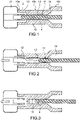
- a conventional nozzle 10 is shown in figures 1 to 4 . It comprises the following parts:
- the first internal volume 12 of the nozzle 10 is configured to accommodate the female contact 2. During the various phases of operations, the female contact 2 typically remains in the first volume 12. The male contact 4 is caused to move between various phases of operations in the axial passage 13.
- the axial passage 13 is configured to accommodate the moving contact 4 and has typically a section narrowed compared to the first and second volumes 12, 14 of the nozzle 10.
- the male contact 4 When the circuit breaker is in closed position ( figure 1 ), the male contact 4 extends into the second volume 14, into the axial passage 13 and into the first volume 12. To cut the current, the male contact 4 and the female contact 2 are moved away from each other ( figures 2 and 3 ), so that the male contact 4 leaves the first volume 12 and moves in the axial passage 13 towards the second volume 14. During the "opening", the male contact 4 must be well aligned with the nozzle axial passage 13 in order to avoid mechanical high speed impact and damage of the circuit-breaker. In that purpose, the gap between the male contact 4 and the inner wall of the axial passage 13 is rarely lower than 1 mm.
- the electrical field on the male contact 4 and female contact 2 increases until arc ignition between them.
- the nozzle axial passage 13 may be provided rather long. Due to vibration or a wrong alignment there is a risk of mechanical contact between the male contact 4 tip and the nozzle 10 inner wall 11 in the axial passage 13 ( figure 3 ). This may induce the arc ignition along the nozzle neck earlier in the closing process, or the arc uncontrolled re-ignition in the opening process. This phenomenon is accentuated by a high tangential electrical field on the nozzle neck surface 11 and leads to a higher risk of damaging the nozzle by the arc.
- the axial passage 13 usually have a constant diameter D and the gap between the male contact 4 and the inner wall 11 of the nozzle neck is rarely lower than 1 mm.
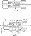
- the gas pressure rise is one of the most important parameter for current breaking. But as described above, the space between the male contact 4 and the nozzle neck inner wall is provided in order to prevent mechanical impact of the pin on the nozzle. Consequently, the pressure rise is not optimized for current breaking. There is also a risk of contact of the pin inside the nozzle neck when opening and closing at high travel speed, leading to uncontrolled arc ignition and a risk of nozzle damage ( figures 3 and 4 ).
- an embodiment of the present invention provides a nozzle for a circuit breaker comprising:
- Such a configuration enables better guidance of a moving contact in the axial passage and reduces the risk of pin impact in a high electrical field area. It further participates to obtain higher pressure blast.
- the axial passage may comprise a narrowing between the first region and the second region.
- the narrowing may have a linearly decreasing section from the first region to the second region.
- the first region has a first length L 1 and the second region has a second length L 2 , said second length L 2 being lower than said first length L 1 .
- the axial passage is defined by a wall made of dielectric material such as a fluoropolymer or a ceramic material.
- the invention further provides a medium-, high-, or very high-voltage circuit breaker comprising an electric arc-blast nozzle such as defined above.
- the circuit breaker typically further provides two arc contacts that can be axially moved in relation to each other, between a circuit breaker opening position in which the arc contacts and are separated from each other and a circuit breaker closing position in which the arc contacts and are in contact with each other, said two arc contacts comprising a female arc contact arranged in said first volume and a male contact.
- Figures 5-8 show a part of a circuit breaker provided with an electric arc-blast nozzle 100 according to an embodiment of the present invention.
- the male contact 40 is not shown in order to facilitate reading.
- the nozzle 100 comprises a first end 100a part extending on a first side and defining internally a first volume 120, a second end 100c part extending on a second side opposite said first side, and defining internally a second volume 140 that is situated opposite the first volume.
- the nozzle 100 further comprises a median 100b neck-forming part between said end parts 100a, 100c and defining internally an axial passage 130 that is situated between the first volume 120 and the second volume 140 and communicates with the first volume 120 and the second volume 140.
- These parts 100a, 100b, 100c may have a symmetrical revolution around axis A'A (i.e. an axis parallel to the x-axis of an orthogonal marker [O; x; y; z] given in the figures.
- the end parts 100a and 100c respectively receive and surround arc contacts 20 and 40.
- the first end part 100a may be disposed upstream and the second end part 100b disposed downstream in the direction of the flow of an electric arc cut-off gas.
- a pressurized gas is accumulated inside an expansion volume 121 located outside the nozzle 100 and communicating with the first volume 120 of the nozzle. After, passing though the axial passage 130, the pressurized gas is expelled of the nozzle 10 via the second volume 140.
- the axial passage 130 has a smaller cross-section than that of the first volume 120 since the latter accommodates a first arc contact 20, which is typically a female contact 20 e.g. in the form of a tulip contact. This female contact 20 is attached to the nozzle 100.
- the axial passage 130 is configured to accommodate only a second arc contact (not represented in figure 5 ) which is a male contact 40 e.g. in the form of a pin contact.
- the axial passage 130 has the particularity of not having a constant section and is, in the present case, provided with regions 131, 132 of different sections.
- the axial passage 130 comprises, in the extension of the first volume 120, a first region 131 communicating with the first volume 120 and with a first cross section.
- the axial passage 130 further comprises a second region 132 of section narrowed relative to the first region 131.
- the second region 132 of the axial passage 130 is thus provided with a second cross section smaller than the first cross section.
- cross section it is here meant a section taken orthogonally to a longitudinal direction defined parallel to the x-axis of the reference system [O; x; y; z].
- the axial passage 130 is provided with a narrowing.
- Such a configuration of the axial passage 130 located in the median part 100b of the nozzle 100 is provided, in order to limit a contact between a moving arc male contact 40 and the internal wall 135 of the nozzle 100 in a critical region of the nozzle 100, that is to say in the vicinity of the female contact 20. It further allows a lower leak between the male contact 40 and the nozzle 100 internal wall and enables higher pressure blast. A better guidance of the moving contact 40 is also obtained. It reduces the risk of pin impact in high electrical field area on the nozzle 100 neck 100b. With such a configuration, the formation of triple points, the metallization of the insulator inner wall in the first region 131 are avoided and thus the unexpected formation of arcs at this surface is avoided.
- the second diameter D2 may correspond substantially to the diameter of an axial passage of a conventional nozzle.
- the first diameter D 1 may be for example between 19 and 21 mm whereas the second diameter D2 may be for example 18mm.
- the first region 131 of larger cross-section is preferably provided with a first length L 1 greater than the second length L 2 of the second region 132 (L 1 and L 2 being dimensions measured parallel to the longitudinal axis of the nozzle parallel to an x-axis of the orthogonal mark [O;°x;°y;°z]).
- L 1 and L 2 being dimensions measured parallel to the longitudinal axis of the nozzle parallel to an x-axis of the orthogonal mark [O;°x;°y;°z]).
- the second length L 2 may be comprised between 50% and 70% of the total L axial passage length.
- the first length L 1 may be for example between 50 and 70mm whereas the second length L2 may be for example between 50 and 30 mm.
- inner wall of the axial passage 130 is such that the change of section between the first region 131 and the second region 132 of the axial passage 130 is done gradually.
- An intermediate region 133 of decreasing cross section is thus advantageously provided between said first region 131 and said second region 132 of the axial passage 130.
- the intermediate region 133 can in particular be delimited by means of a frustoconical part 133a between the first region 131 and the second region 132.
- the intermediate region 133 may have thus a linearly decreasing section from the first region 131 to the second region 132.
- the nozzle 100 is typically made of at least a dielectric material.
- the axial passage 130 is delimited by wall(s) 131a, 132a, 133a that is/are typically formed of at least a dielectric or insulating material.
- This material can be e.g a composition comprising a fluorocarbon polymer matrix, such as polytetrafluoroethylene (PTFE), or a ceramic material.
- PTFE polytetrafluoroethylene
- the circuit breaker is shown in a closed position wherein arc contacts 20, 40 are in contact with one other such that a current can flow.
- the male arc contact 40 closes the axial passage 130 of the nozzle partially and extends up to the first volume 120.
- Figure 8 shows a closing operation in a particular case due to the effect of a potential vibration or to a misalignment of the male contact 40 in the axial passage 130. Due to the configuration of the axial passage 130, the pin is better guided. Possible metallic traces left on the nozzle inner surface 131a near the tulip contact is avoided, which is particularly important during closing operation under high voltage condition. The pin cannot impact the nozzle neck in the critical area of high electric field close to tulip contact during closing under high voltage condition.
- An arrangement as described above is situated in an arc-control chamber of the circuit breaker.
- the arc-control chamber is typically arranged inside a casing.
- the arc-control chamber is thus placed in a space that is internally defined by this casing. This space is usually filled with an insulating gas, such as SF6 or dry air or nitrogen or carbon dioxide CO 2 or a gaseous mix comprising mainly CO 2 .
- the chamber includes another set of electrical contacts (not shown) comprising a first main contact cooperating with a second main contact.
- a nozzle as described above can be adapted to various circuit breakers from medium-voltage to high-voltage circuit breakers, i.e. operating at voltages typically ranging between 52 kV and 1200 kV.
- the invention is not limited to a circuit breaker as described above with one fixed and one moving contact.
- the invention may in particular be applied to double-motion circuit breakers.
Landscapes
- Circuit Breakers (AREA)
Abstract
Description
- The present invention relates to an improved nozzle intended to be included in a medium- or high- or very high-voltage circuit breaker and also to a medium- or high- or very high-voltage circuit breaker including such a nozzle.
- A circuit breaker is an automatically operated electrical switch designed to protect an electrical circuit from damage caused by excess current, typically resulting from an overload or a short circuit. Once a fault is detected, the circuit breaker contacts open and separate to interrupt the circuit. A high voltage circuit breaker generally comprises at least one
female arc contact 2, also called "tulip contact" that is typically made of contact fingers in a shape of tulip, and at least onemale arc contact 4 that may be in a shape of a pin and called "pin contact". Such a device further includes aninsulating nozzle 10 that is mechanically attached to thefemale contact 2. - During an opening operation of the circuit breaker that is conducted to interrupt current, a moving contact, typically the
male contact 4, is traveling inside a nozzle internal passage while thecontacts - Thus, when a high current or voltage is interrupted, an electrical arc is generated between the contacts and such arc must be terminated. The strong radiations generated by this arc inside the nozzle passage evaporate the nozzle material and generate locally high pressure and heat. A part of pressurized gas is accumulated inside an
expansion volume 21 and will help to extinguish the arc by blowing on it at the end of the interruption process. Thenozzle 10 is thus configured to participate to the blow out the arc. - A
conventional nozzle 10 is shown infigures 1 to 4 . It comprises the following parts: - a
median part 10b also called "neck" internally defining anaxial passage 13, - a
first end 10a part extending on a first side of the median part and defining internally afirst volume 12 communicating with theaxial passage 13, - a
second end 10c part extending on a second side of the median part opposite said first side, said second end part defining internally asecond volume 14 communicating with theaxial passage 13 and situated opposite the first volume. - The first
internal volume 12 of thenozzle 10 is configured to accommodate thefemale contact 2. During the various phases of operations, thefemale contact 2 typically remains in thefirst volume 12. Themale contact 4 is caused to move between various phases of operations in theaxial passage 13. Thus, theaxial passage 13 is configured to accommodate the movingcontact 4 and has typically a section narrowed compared to the first andsecond volumes nozzle 10. - When the circuit breaker is in closed position (
figure 1 ), themale contact 4 extends into thesecond volume 14, into theaxial passage 13 and into thefirst volume 12. To cut the current, themale contact 4 and thefemale contact 2 are moved away from each other (figures 2 and 3 ), so that themale contact 4 leaves thefirst volume 12 and moves in theaxial passage 13 towards thesecond volume 14. During the "opening", themale contact 4 must be well aligned with the nozzleaxial passage 13 in order to avoid mechanical high speed impact and damage of the circuit-breaker. In that purpose, the gap between themale contact 4 and the inner wall of theaxial passage 13 is rarely lower than 1 mm. - While approaching the
contacts male contact 4 andfemale contact 2 increases until arc ignition between them. In the case of very high voltage, the nozzleaxial passage 13 may be provided rather long. Due to vibration or a wrong alignment there is a risk of mechanical contact between themale contact 4 tip and thenozzle 10inner wall 11 in the axial passage 13 (figure 3 ). This may induce the arc ignition along the nozzle neck earlier in the closing process, or the arc uncontrolled re-ignition in the opening process. This phenomenon is accentuated by a high tangential electrical field on thenozzle neck surface 11 and leads to a higher risk of damaging the nozzle by the arc. - In order to respond to the requirements listed above, the
axial passage 13 usually have a constant diameter D and the gap between themale contact 4 and theinner wall 11 of the nozzle neck is rarely lower than 1 mm. - However, the gas pressure rise is one of the most important parameter for current breaking. But as described above, the space between the
male contact 4 and the nozzle neck inner wall is provided in order to prevent mechanical impact of the pin on the nozzle. Consequently, the pressure rise is not optimized for current breaking. There is also a risk of contact of the pin inside the nozzle neck when opening and closing at high travel speed, leading to uncontrolled arc ignition and a risk of nozzle damage (figures 3 and4 ). - There is therefore a need to find a new circuit breaker structure that is improved with respect to at least one of the disadvantages listed above.
- According to a particular aspect, an embodiment of the present invention provides a nozzle for a circuit breaker comprising:
- a median part internally defining an axial passage for a male arc contact,
- a first end part extending on a first side of the median part, said first end part defining internally a first volume for a female arc contact, said first volume communicating with said axial passage and being configured to receive a female arc contact,
- a second end part extending on a second side of the median part opposite said first side, said second end part defining internally a second volume for said male arc contact, the axial passage having, in a direction going from the first volume towards the second volume, a first region communicating with the first volume and provided with a first cross section, in the extension of the first region, a second region communicating with the second volume, the second region having a narrowed cross section relative to the first cross section.
- Such a configuration enables better guidance of a moving contact in the axial passage and reduces the risk of pin impact in a high electrical field area. It further participates to obtain higher pressure blast.
- Advantageously, the axial passage may comprise a narrowing between the first region and the second region.
- According to an embodiment, the narrowing may have a linearly decreasing section from the first region to the second region.
- Advantageously, the first region has a first length L1 and the second region has a second length L2, said second length L2 being lower than said first length L1.
- According to a particular embodiment, the axial passage is defined by a wall made of dielectric material such as a fluoropolymer or a ceramic material.
- The invention further provides a medium-, high-, or very high-voltage circuit breaker comprising an electric arc-blast nozzle such as defined above.
- The circuit breaker typically further provides two arc contacts that can be axially moved in relation to each other, between a circuit breaker opening position in which the arc contacts and are separated from each other and a circuit breaker closing position in which the arc contacts and are in contact with each other, said two arc contacts comprising a female arc contact arranged in said first volume and a male contact.
- The present invention will be better understood on reading the description of exemplary embodiments given, purely as an indication and in no way limiting, with reference to the appended drawings in which:
-
Figure 1 shows a partial schematic longitudinal section of a circuit breaker comprising an electric art blast nozzle according to the prior art, the circuit breaker being shown in a closed position"; -
Figure 2 shows the same circuit breaker during an opening operation"; -
Figure 3 shows the same circuit breaker shown during opening operation, when a male contact is misaligned°; -
Figure 4 shows the same circuit breaker during closing operation, also with a misaligned position of the male contact in the axial passage of the nozzle neck"; -
Figure 5 shows a partial schematic longitudinal section of a circuit breaker comprising a nozzle implemented according to an embodiment of the present invention"; -
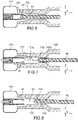
Figure 6 shows a partial schematic longitudinal section of a circuit breaker comprising a nozzle implemented according to an embodiment of the present invention, in a closed position of the circuit breaker wherein the arc contacts are in contact with one other"; -
Figure 7 shows a partial schematic longitudinal section of a circuit breaker comprising a nozzle implemented according to an embodiment of the present invention, during opening operation of the circuit breaker"; -
Figure 8 shows a partial schematic longitudinal section of a circuit breaker comprising a nozzle implemented according to an embodiment of the present invention, during opening or closing operation in case a male arc contact is subject to vibrations"; -
Figures 5-8 show a part of a circuit breaker provided with an electric arc-blast nozzle 100 according to an embodiment of the present invention. - In the partial view given in
figure 5 , themale contact 40 is not shown in order to facilitate reading. - The
nozzle 100 comprises afirst end 100a part extending on a first side and defining internally afirst volume 120, asecond end 100c part extending on a second side opposite said first side, and defining internally asecond volume 140 that is situated opposite the first volume. Thenozzle 100 further comprises a median 100b neck-forming part between saidend parts axial passage 130 that is situated between thefirst volume 120 and thesecond volume 140 and communicates with thefirst volume 120 and thesecond volume 140. - These
parts end parts arc contacts - The
first end part 100a, may be disposed upstream and thesecond end part 100b disposed downstream in the direction of the flow of an electric arc cut-off gas. - In the extension of the first end of the
nozzle 100, a pressurized gas is accumulated inside anexpansion volume 121 located outside thenozzle 100 and communicating with thefirst volume 120 of the nozzle. After, passing though theaxial passage 130, the pressurized gas is expelled of thenozzle 10 via thesecond volume 140. - The
axial passage 130 has a smaller cross-section than that of thefirst volume 120 since the latter accommodates afirst arc contact 20, which is typically afemale contact 20 e.g. in the form of a tulip contact. Thisfemale contact 20 is attached to thenozzle 100. Theaxial passage 130 is configured to accommodate only a second arc contact (not represented infigure 5 ) which is amale contact 40 e.g. in the form of a pin contact. - An improved profile of the insulating
nozzle 100inner wall 135 is here proposed. Theaxial passage 130 has the particularity of not having a constant section and is, in the present case, provided withregions axial passage 130 comprises, in the extension of thefirst volume 120, afirst region 131 communicating with thefirst volume 120 and with a first cross section. In the extension of thefirst region 131 of thepassage 130, theaxial passage 130 further comprises asecond region 132 of section narrowed relative to thefirst region 131. Thesecond region 132 of theaxial passage 130 is thus provided with a second cross section smaller than the first cross section. By "cross section" it is here meant a section taken orthogonally to a longitudinal direction defined parallel to the x-axis of the reference system [O; x; y; z]. - Hence, in a direction taken from the
first end 100a of thenozzle 100 on the side of afemale contact 20 to thesecond end 100b of the nozzle opposite to thefirst end 100a, theaxial passage 130 is provided with a narrowing. - Such a configuration of the
axial passage 130 located in themedian part 100b of thenozzle 100 is provided, in order to limit a contact between a moving arcmale contact 40 and theinternal wall 135 of thenozzle 100 in a critical region of thenozzle 100, that is to say in the vicinity of thefemale contact 20. It further allows a lower leak between themale contact 40 and thenozzle 100 internal wall and enables higher pressure blast. A better guidance of the movingcontact 40 is also obtained. It reduces the risk of pin impact in high electrical field area on thenozzle 100neck 100b. With such a configuration, the formation of triple points, the metallization of the insulator inner wall in thefirst region 131 are avoided and thus the unexpected formation of arcs at this surface is avoided. - In the median part of the
nozzle 100, instead of having anaxial passage 130 with an inner diameter that is constant or increasing in the direction of themale contact 40, here is provided anaxial passage 130 with asecond region 132 having a diameter D2 that is reduced compared to that D1 of the first region 131 (D1, D2 being dimensions measured parallel to γ-axis of an orthogonal mark [O;°x;°y;°z] given in the Figures), thereby reducing the gas flow out of thenozzle 100. The second diameter D2 may correspond substantially to the diameter of an axial passage of a conventional nozzle. - According to a particular example, the first diameter D1 may be for example between 19 and 21 mm whereas the second diameter D2 may be for example 18mm.
- In the
axial passage 130, thefirst region 131 of larger cross-section is preferably provided with a first length L1 greater than the second length L2 of the second region 132 (L1 and L2 being dimensions measured parallel to the longitudinal axis of the nozzle parallel to an x-axis of the orthogonal mark [O;°x;°y;°z]). Thus, in combination with the narrowing, this helps to minimize potential metallization of the inner wall of thenozzle 100 when themale arc contact 40 moves. - The second length L2 may be comprised between 50% and 70% of the total L axial passage length.
- According to a particular example, the first length L1 may be for example between 50 and 70mm whereas the second length L2 may be for example between 50 and 30 mm.
- To promote the circulation and ejection of gas out of the
nozzle 100, inner wall of theaxial passage 130 is such that the change of section between thefirst region 131 and thesecond region 132 of theaxial passage 130 is done gradually. Anintermediate region 133 of decreasing cross section is thus advantageously provided between saidfirst region 131 and saidsecond region 132 of theaxial passage 130. Theintermediate region 133 can in particular be delimited by means of a frustoconical part 133a between thefirst region 131 and thesecond region 132. Theintermediate region 133 may have thus a linearly decreasing section from thefirst region 131 to thesecond region 132. - The
nozzle 100 is typically made of at least a dielectric material. Theaxial passage 130 is delimited by wall(s) 131a, 132a, 133a that is/are typically formed of at least a dielectric or insulating material. This material can be e.g a composition comprising a fluorocarbon polymer matrix, such as polytetrafluoroethylene (PTFE), or a ceramic material. - In
Figure 6 , the circuit breaker is shown in a closed position whereinarc contacts arc contacts male arc contact 40 closes theaxial passage 130 of the nozzle partially and extends up to thefirst volume 120. - In
Figure 7 , the circuit breaker is then shown during opening, thefirst region 131 of theaxial passage 130 with increased diameter being provided with an inner surface SV ofvaporization 131a that is larger. Therefore the pressure increase during arc extinction is higher. There is an electric arc cut-off gas routing channel between themale arc contact 40 and thewall 132a of thesecond region 132, which allows the circulation of gas in theaxial passage 130, from its inlet to its outlet, to cut an electric arc that is likely to be formed during the movement ofarc contacts male contact 40 is lower in thesecond region 132, so the pneumatic and self-blast effect for arc extinction during opening is not reduced. -
Figure 8 shows a closing operation in a particular case due to the effect of a potential vibration or to a misalignment of themale contact 40 in theaxial passage 130. Due to the configuration of theaxial passage 130, the pin is better guided. Possible metallic traces left on the nozzleinner surface 131a near the tulip contact is avoided, which is particularly important during closing operation under high voltage condition. The pin cannot impact the nozzle neck in the critical area of high electric field close to tulip contact during closing under high voltage condition. - An arrangement as described above is situated in an arc-control chamber of the circuit breaker. The arc-control chamber is typically arranged inside a casing. The arc-control chamber is thus placed in a space that is internally defined by this casing. This space is usually filled with an insulating gas, such as SF6 or dry air or nitrogen or carbon dioxide CO2 or a gaseous mix comprising mainly CO2.
- Besides the above mentioned arcing contacts, the chamber includes another set of electrical contacts (not shown) comprising a first main contact cooperating with a second main contact.
- A nozzle as described above can be adapted to various circuit breakers from medium-voltage to high-voltage circuit breakers, i.e. operating at voltages typically ranging between 52 kV and 1200 kV.
- The invention is not limited to a circuit breaker as described above with one fixed and one moving contact. The invention may in particular be applied to double-motion circuit breakers.
Claims (6)
- An electric arc-blast nozzle (100) for a circuit breaker comprising:- a median part (100b) internally defining an axial passage (130) for a male arc contact,- a first end part (100a) extending on a first side of the median part, said first end part defining internally a first volume (120) for a female arc contact, said first volume (120) communicating with said axial passage (130),- a second end part (100c) extending on a second side of the median part opposite said first side, said second end part defining internally a second volume (140) for said male arc contact, the axial passage having, in a direction going from the first volume towards the second volume, a first region (131) communicating with the first volume (120) and provided with a first cross section, and in the extension of the first region, a second region (132) communicating with the second volume (140), the second region (132) having a narrowed cross section relative to said first cross section.
- A nozzle (100) according to claim 1, wherein the axial passage (130) comprises an intermediate region (133) with a narrowing section between the first region (131) and the second region (132).
- A nozzle (100) according to claim 1 or 2, said intermediate region (133) having a linearly decreasing section from the first region (131) to the second region (132).
- A nozzle (100) according to any of the claims 1 to 3, wherein the first region (131) has a first length L1 and wherein the second region (132) has a second length L2, said second length L2 being lower than said first length L1.
- A nozzle (100) according to any of the claims 1 to 4, wherein the axial passage (130) is defined by a wall made of dielectric material such as a fluoropolymer or a ceramic material.
- A medium-, high-, or very high-voltage circuit breaker comprising:- an electric arc-blast nozzle (100) such as defined according to any one of the claims 1 to 4,- at least two arc contacts that can be axially moved in relation to each other, between a circuit breaker opening position in which the arc contacts (20) and (40) are separated from each other and a circuit breaker closing position in which the arc contacts (20) and (40) are in contact with each other, said two arc contacts comprising a female arc contact (20) arranged in said first volume and a male contact.
Priority Applications (2)
| Application Number | Priority Date | Filing Date | Title |
|---|---|---|---|
| EP21160769.2A EP4053873A1 (en) | 2021-03-04 | 2021-03-04 | Insulating nozzle for circuit breaker with improved inner configuration |
| PCT/EP2022/055382 WO2022184818A1 (en) | 2021-03-04 | 2022-03-03 | Insulating nozzle for circuit breaker with improved inner configuration |
Applications Claiming Priority (1)
| Application Number | Priority Date | Filing Date | Title |
|---|---|---|---|
| EP21160769.2A EP4053873A1 (en) | 2021-03-04 | 2021-03-04 | Insulating nozzle for circuit breaker with improved inner configuration |
Publications (1)
| Publication Number | Publication Date |
|---|---|
| EP4053873A1 true EP4053873A1 (en) | 2022-09-07 |
Family
ID=74858367
Family Applications (1)
| Application Number | Title | Priority Date | Filing Date |
|---|---|---|---|
| EP21160769.2A Withdrawn EP4053873A1 (en) | 2021-03-04 | 2021-03-04 | Insulating nozzle for circuit breaker with improved inner configuration |
Country Status (2)
| Country | Link |
|---|---|
| EP (1) | EP4053873A1 (en) |
| WO (1) | WO2022184818A1 (en) |
Citations (2)
| Publication number | Priority date | Publication date | Assignee | Title |
|---|---|---|---|---|
| DE102015205388A1 (en) * | 2015-03-25 | 2016-09-29 | Siemens Aktiengesellschaft | Insulating nozzle and electrical switching device with the insulating nozzle |
| WO2018024435A1 (en) * | 2016-08-02 | 2018-02-08 | Siemens Aktiengesellschaft | Interrupter unit for a circuit breaker |
-
2021
- 2021-03-04 EP EP21160769.2A patent/EP4053873A1/en not_active Withdrawn
-
2022
- 2022-03-03 WO PCT/EP2022/055382 patent/WO2022184818A1/en not_active Ceased
Patent Citations (2)
| Publication number | Priority date | Publication date | Assignee | Title |
|---|---|---|---|---|
| DE102015205388A1 (en) * | 2015-03-25 | 2016-09-29 | Siemens Aktiengesellschaft | Insulating nozzle and electrical switching device with the insulating nozzle |
| WO2018024435A1 (en) * | 2016-08-02 | 2018-02-08 | Siemens Aktiengesellschaft | Interrupter unit for a circuit breaker |
Also Published As
| Publication number | Publication date |
|---|---|
| WO2022184818A1 (en) | 2022-09-09 |
Similar Documents
| Publication | Publication Date | Title |
|---|---|---|
| US9058947B2 (en) | Puffer-type gas circuit-breaker | |
| KR20020069090A (en) | Gas circuit breaker | |
| US10964498B2 (en) | Gas-insulated low- or medium-voltage load break switch | |
| US20150014279A1 (en) | Device For Protection Against Particles Generated By An Electric Switching Arc | |
| CN1065069C (en) | Puffer type gas circuit breaker | |
| AU2018217779A1 (en) | Arc splitter plate | |
| WO2022184818A1 (en) | Insulating nozzle for circuit breaker with improved inner configuration | |
| US5159164A (en) | Gas circuit breaker | |
| JPH05190064A (en) | Electric contactor | |
| EP4246548A1 (en) | Interrupter unit for gas-insulated high or medium voltage device and gas-insulated high or medium voltage device | |
| KR0158695B1 (en) | Puffer type gas circuit interrupter | |
| EP3611745B1 (en) | Gas-insulated low- or medium-voltage load break switch | |
| EP2827353A1 (en) | Electrical switching device | |
| US20250149276A1 (en) | Switching device with an isolating or earthing function | |
| JPH0114652B2 (en) | ||
| KR101508442B1 (en) | Circuit breaker of gas insulation switchgear | |
| JP7822532B1 (en) | earthing switch | |
| KR20240151011A (en) | Gas insulated circuit breaker | |
| RU2207648C1 (en) | Arc-control device for gas-filled high-voltage pufferbreaker | |
| US20260120967A1 (en) | Disconnector contact system with controlled discharge | |
| JP2512502Y2 (en) | Gas insulated disconnector | |
| RU2153205C1 (en) | Arc-control device of gas-filled self-compression high-voltage circuit breaker | |
| EP4672291A3 (en) | Gas-insulated high or medium voltage circuit breaker | |
| RU2148281C1 (en) | Arc-control device of self-compression gas-filled high-voltage switch | |
| SU1709411A1 (en) | Load high-voltage gas-blast circuit breaker |
Legal Events
| Date | Code | Title | Description |
|---|---|---|---|
| PUAI | Public reference made under article 153(3) epc to a published international application that has entered the european phase |
Free format text: ORIGINAL CODE: 0009012 |
|
| STAA | Information on the status of an ep patent application or granted ep patent |
Free format text: STATUS: THE APPLICATION HAS BEEN PUBLISHED |
|
| AK | Designated contracting states |
Kind code of ref document: A1 Designated state(s): AL AT BE BG CH CY CZ DE DK EE ES FI FR GB GR HR HU IE IS IT LI LT LU LV MC MK MT NL NO PL PT RO RS SE SI SK SM TR |
|
| STAA | Information on the status of an ep patent application or granted ep patent |
Free format text: STATUS: REQUEST FOR EXAMINATION WAS MADE |
|
| 17P | Request for examination filed |
Effective date: 20230209 |
|
| RBV | Designated contracting states (corrected) |
Designated state(s): AL AT BE BG CH CY CZ DE DK EE ES FI FR GB GR HR HU IE IS IT LI LT LU LV MC MK MT NL NO PL PT RO RS SE SI SK SM TR |
|
| P01 | Opt-out of the competence of the unified patent court (upc) registered |
Effective date: 20230522 |
|
| STAA | Information on the status of an ep patent application or granted ep patent |
Free format text: STATUS: THE APPLICATION IS DEEMED TO BE WITHDRAWN |
|
| 18D | Application deemed to be withdrawn |
Effective date: 20241001 |