EP4053795A1 - Procédé et système pour capture 3d en temps réel et rétroaction en direct avec des caméras monoculaires - Google Patents
Procédé et système pour capture 3d en temps réel et rétroaction en direct avec des caméras monoculaires Download PDFInfo
- Publication number
- EP4053795A1 EP4053795A1 EP22167743.8A EP22167743A EP4053795A1 EP 4053795 A1 EP4053795 A1 EP 4053795A1 EP 22167743 A EP22167743 A EP 22167743A EP 4053795 A1 EP4053795 A1 EP 4053795A1
- Authority
- EP
- European Patent Office
- Prior art keywords
- information
- image
- electronic device
- camera
- portable electronic
- Prior art date
- Legal status (The legal status is an assumption and is not a legal conclusion. Google has not performed a legal analysis and makes no representation as to the accuracy of the status listed.)
- Pending
Links
Images


Classifications
-
- G—PHYSICS
- G06—COMPUTING; CALCULATING OR COUNTING
- G06T—IMAGE DATA PROCESSING OR GENERATION, IN GENERAL
- G06T15/00—3D [Three Dimensional] image rendering
- G06T15/10—Geometric effects
- G06T15/20—Perspective computation
- G06T15/205—Image-based rendering
-
- G—PHYSICS
- G06—COMPUTING; CALCULATING OR COUNTING
- G06T—IMAGE DATA PROCESSING OR GENERATION, IN GENERAL
- G06T17/00—Three dimensional [3D] modelling, e.g. data description of 3D objects
- G06T17/20—Finite element generation, e.g. wire-frame surface description, tesselation
-
- G—PHYSICS
- G06—COMPUTING; CALCULATING OR COUNTING
- G06T—IMAGE DATA PROCESSING OR GENERATION, IN GENERAL
- G06T7/00—Image analysis
- G06T7/50—Depth or shape recovery
- G06T7/55—Depth or shape recovery from multiple images
-
- G—PHYSICS
- G06—COMPUTING; CALCULATING OR COUNTING
- G06T—IMAGE DATA PROCESSING OR GENERATION, IN GENERAL
- G06T2200/00—Indexing scheme for image data processing or generation, in general
- G06T2200/24—Indexing scheme for image data processing or generation, in general involving graphical user interfaces [GUIs]
-
- G—PHYSICS
- G06—COMPUTING; CALCULATING OR COUNTING
- G06T—IMAGE DATA PROCESSING OR GENERATION, IN GENERAL
- G06T2207/00—Indexing scheme for image analysis or image enhancement
- G06T2207/10—Image acquisition modality
- G06T2207/10016—Video; Image sequence
-
- G—PHYSICS
- G06—COMPUTING; CALCULATING OR COUNTING
- G06T—IMAGE DATA PROCESSING OR GENERATION, IN GENERAL
- G06T2207/00—Indexing scheme for image analysis or image enhancement
- G06T2207/30—Subject of image; Context of image processing
- G06T2207/30196—Human being; Person
-
- G—PHYSICS
- G06—COMPUTING; CALCULATING OR COUNTING
- G06T—IMAGE DATA PROCESSING OR GENERATION, IN GENERAL
- G06T2207/00—Indexing scheme for image analysis or image enhancement
- G06T2207/30—Subject of image; Context of image processing
- G06T2207/30196—Human being; Person
- G06T2207/30201—Face
Definitions
- Embodiments may be implemented in a portable electronic device with a camera.
- a smartphone is used as an example of such a portable electronic device.
- Processing techniques as described herein can assemble image frames depicting an object into a 3D map of the object using a relatively small amount of processing power, such that a processor of a portable electronic device may perform the processing fast enough that a 3D image may be constructed in real-time with sufficient image information to allow a user to see which portions of the object have been adequately scanned and which portions require additional image information to be acquired.
- key frames may be processed in about 300-600 ms, while frames between the key frames may be processed in about 10-50 ms.
- key frames may be processed in about 500 ms and other frames in about 20ms using a commercially available smartphone processor. Processing at this speed enables a visualization of the object to be presented in real time as it is being scanned with the portable electronic device.
- the present application describes a software 3D camera approach (i.e. emulating the output properties of a hardware 3D camera) yielding in a real-time What-You-See-Is-What-You-Get experience for creating 3D printable models that is so efficient and robust that it can run on regular smartphones.
- the processing described herein may be implemented by computer-executable instructions executing on a processor in the smartphone. That processing may produce a depth map of an object, which may be rendered on a display of the smartphone using smartphone hardware, such as a GPU.
- the described processing techniques build on proven principles of real-time robotics [see for example references 4, 5, 6, 10, 11 for suitable techniques] and applies them to a real-time feedback system for 3D scanning, which may be used where a human is in control of moving a camera and exposed to a live 3D reconstruction as feedback.
- techniques as described herein may be used for capturing images.
- the techniques may be used to implement a 3D camera, using software. That software may execute on a portable electronic device (such as a smartphone) with a camera supplying images, a processor to process those images and a display to visually display the images and/or visual representations of a model constructed from the images and/or other information.
- a portable electronic device such as a smartphone
- a processor to process those images
- a display to visually display the images and/or visual representations of a model constructed from the images and/or other information.
- some or all of the image processing may be performed on a computing device coupled to an electronic device with a camera to capture images.
- techniques as described herein may be used to simulate a hardware 3D camera by processing image frames acquired with a monocular camera on a portable electronic device that is being moved to capture image frames from different perspectives.
- a system and method for a real-time, monocular depth camera based on multiple image frames and probabilistic depth-measurements is presented.
- the system uses a frequency-triggered key frame approach to provide depth maps at constant rate similar to a hardware 3D camera (stereo camera with or without additional time-of-flight or structured light measurements).
- a frequency-triggered key frame approach may be implemented by designating captured frames as "key frames" at a specific frequency.
- These key frames may be analyzed to determine image characteristics, including a dense depth map representing depth between numerous points on surfaces of objects depicted in the key frame and a point representing the point of view of the 3D image being formed.
- Frames between key frames in a sequence of images being captured may be processed to produce a sparse depth map.
- the sparse depth map may have depths computed for fewer points than the dense depth map.
- the sparse depth map may have 60-80% as many points as the dense depth map, or between 40-60%, or 20-40% or fewer.
- the number of points in the sparse depth map may be dynamically selected based on factors such as processor speed, frame capture rate and/or speed at which the portable electronic device is being moved while the sequence of images is being captured. The processing of the intervening images may be performed on lower resolution versions of the image.
- the system uses a motion-based key frame triggering strategy to provide depth information based on movement of the device.
- the system uses a user-facing camera of a smartphone to capture the sequence of image frames.
- the system uses a world-facing camera of a smartphone to capture the sequence of image frames.
- the system is used to complement a hardware 3D camera as a fail-over in certain light conditions (e.g. in bright sunlight the Infrared projection of ToF/Structured doesn't work) or distances (the IR projection of hardware 3D cameras has issues operating at very short distances such as smaller than three feet or larger than ten feet).
- certain light conditions e.g. in bright sunlight the Infrared projection of ToF/Structured doesn't work
- distances the IR projection of hardware 3D cameras has issues operating at very short distances such as smaller than three feet or larger than ten feet.
- App-based 3D Scanning and real-time feedback i.e. creating a live view of a reconstructed & textured 3D mesh, "What you see is what you get"
- a system and method for a real-time 3D model reconstruction with a monocular camera is presented.
- Such a system may be implemented as computer-executable instructions encoded for execution on a processor of a smartphone, in a format considered an "app," which may execute entirely on the smart phone or through interaction with a server or other computing device where some or all of the processing described herein may be performed.
- Embodiments of such a system use local and global optimization based on probabilistic depth-maps to improve the quality of the mesh in real-time with the user's help.
- the system uses live meshing and texturing to visualize which areas have been captured in enough quality and to guide the user.
- a depth map created as a composite of the dense depth maps created from key frames and sparse depth maps created from other frames may be used to create a mesh representing surfaces of objects in the image.
- Other image information selected based on position of the surfaces as indicated by the mesh, may be used to determine visual characteristics of these surfaces.
- the system uses live meshing and simple coloring to visualize the capture progress.
- the system uses a feedback based on a priors (i.e. we know what we scan) or basic polygons with simple coloring of already scanned areas.
- the system automatically performs checks for 3D printability and thus guides the user towards areas that require more attention during capturing.
- FIG. 1 illustrates an exemplary work flow in a system in which a camera of a smartphone is used to capture a sequence of image frames of an object.
- the user of the smartphone moves the smartphone so as to capture image frames of the object from multiple points of view. Processing of these image frames may allow points or other features on external surfaces of the object to be identified in the images and correlated.
- Motion information about the smartphone between frames allows a computation of a relative position of the smartphone when different image frames were acquired (using an IMU of the smart phone, for example), allowing the perspective from which features in different image frames were acquired. These differences in perspective provide stereoscopic information from which can be computed a distance between those features and a point of view of a 3D image being formed. This depth information may be used as a 3D model of the object being scanned.
- Motion information may be obtained from sensors on the smartphone, such as may be included in an IMU of the smartphone. Alternatively or additionally, motion information may be computed from information in the image frames.
- this 3D modeling may be performed on image frames as they are acquired such that the 3D model may be depicted to the user as the image frames are being acquired and processed.
- This 3D model may serve as feedback to the user, indicating portions of the object that have been adequately imaged or portions for which additional image frames are required to produce an adequate model.
- this real-time display of information may be based in whole or in part on information that does not provide the desired level of detail of a completed 3D image. All or portions of the real-time feedback image, for example, may have less resolution than a final image.
- the real-time feedback image may be based on a subset of the information that would be depicted in a final image, displaying a mesh representing locations of surfaces while omitting color, texture or other surface characteristics. Using a subset of information to be presented in the final image to display the feedback image may allow the feedback image to be displayed in real-time. Additional information may be stored, as part of the captured image frames or otherwise, and used to complete the final image after scanning of the object is completed.
- the 3D image may be used in any of a number of ways.
- the 3D image optionally may be configured in one or more ways before being used. That configuration, for example, may be performed interactively based on user inputs entered through an interface of the smartphone or in any other suitable way. That configuration may include processing to select the size or other characteristics of the 3D image and may include merging the image with templates representing an object of the type being imaged.
- the configured image may then be passed to an output device or another system.
- the image for example, may be sent to a 3D printer for printing a 3D model of the object that was imaged.
- the 3D image may be provided to a gaming system programmed to accept 3D models of objects (including avatars of people that can be displayed as part of the game. More generally the 3D image may be stored as a 3D model file (in a standardized or custom format) or provided to any other system configured to operate on such a 3D model.
- FIG. 2 illustrates a method of processing a sequence of image frames, which may be taken by a camera on a portable electronic device such that a user may move the device to acquire image frames from different perspectives, thus capturing 3D information. Some or all of the acts depicted in FIG. 2 may be performed while the sequence of images frames is being captured, with processing performed on frames earlier in the sequence while frames later in the sequence are being captured.
- FIG. 2 is described from the perspective of a user operating a smartphone, this hardware is illustrative only.
- the camera may be located within any suitable portable electronic device and/or may be a standalone camera.
- the processing may be performed by programming a processor that receives the captured image frames from the camera hardware. That processor may be physically within the portable electronic device, in a server to which the portable electronic device is connected via a network or in any other suitable processor.
- FIG. 2 An example of processing is shown in FIG. 2 .
- At act 1200 The user starts the capture process by pointing at a desired object with a live viewfinder and invoking the capture button, which may be, in the case of a smartphone, a soft button programmed to appear on a touch screen.
- the algorithm runs in the video mode and works as follows:
- a frame may be identified by: 1) fixed framerate: triggers a key frame for every N incoming frames or 2) motion based: triggers a key frame only if there is significant movement since the last frame. In some embodiments, one strategy for selecting key frames may be used.
- programming on the portable electronic device may support either strategy and user configuration may determine the strategy or the strategy may be selected dynamically based on available processing, frame rate speed at which the user is moving the camera or other factors.
- Speed of motion may be determined, for example, by degree of overlap between successive frames in the sequence. For example, frames in a sequence may be designated as key frames at a rate that provides for greater than 25% overlap between a key frame and a successive image frame in the sequence. In some embodiments, that rate may be greater than 50% or greater than 75% overlap or any other suitable degree of overlap.
- a key frame and other frames may both be processed to produce a depth map.
- the processing on a key frame may produce a denser depth map and/or additional information about visual characteristics of an object being imaged.
- processing on the key frame may take longer than on other frames.
- At act 1208 Performs a basic quality image check (i.e. motion blur detection) and sends the data to the pipeline. It also synchronizes the timestamps of the IMU sensors information with the image.
- a basic quality image check i.e. motion blur detection
- Navigation data may be derived from the outputs of the IMU sensors, indicating relative position of the portable electronic device at the time the image frame was captured. This position may be relative to an origin which may serve as a point of view of the 3D image being captured or represented in any other suitable coordinate system.
- Pose of the camera when the image was acquired may serve as an indication of the orientation of the image frame within the 3D image being constructed. For example, two image frames may have different poses if taken of different portions of the object being imaged or even of the same portion of the object, but with the camera rotated or tilted.
- This pose also serves as an estimate for basic feedback to the user in case block [1212] has lost track, and also serve as an initial estimate for relocalization.
- the user may be instructed, such as by arrows or other indications on a display screen, to return the camera to a pose from which additional image frames can be collected to complete a 3D image.
- Combined tracking and sparse reconstruction Determines a refined pose by using minimizing the photogrammetric error between the current and the previous frame.
- the implementation uses a maximum likelihood estimate for the rigid body transformation to determine the new camera pose based on the camera pose associated with the previous image and a minimization of the photogrammetric error.
- the photogrammetric error is determined based on patches of the size of 8x8 pixels. The patches are placed at interest points based on corners and edgelets (potentially also other feature descriptors). Because a semi-direct approach is chosen, features are extracted only on a key frame. For every subsequent incoming image, the patches themselves track the feature implicit by minimizing the photogrammetric error and therefore the need for a computationally expensive full search operation is omitted. As a result, a sparse depth-map is created and the camera position retrieved.
- the process described in our co-pending application WO2015/173173 may be used. A formal description for this principle can be found in [30]:
- SVO computes an initial guess of the relative camera motion and the feature correspondences using direct methods and concludes with a feature-based nonlinear reprojection-error refinement. Each step is detailed in the following sections and illustrated in Figures 2 to 4 .
- T k,k -1 arg min T ⁇ R ⁇ ⁇ ⁇ I T u d u .
- R is the image region for which the depth d u is known at time k - 1 and for which the back-projected points are visible in the current image domain:
- R ⁇ u
- the frame is sent to the display for retaining a live camera feed. It is sent after pose estimation in block [1212] to ensure that user real-time feedback can be augmented into the frame, but before the dense depth-map calculations in [1222] to keep the latency of the user feedback below 20ms.
- Whether an image is a key frame is defined in block [1204]. At that point, a key frame does not have any depth information available yet.
- the branch illustrated at clock 1218 may be performed only once such that, in the first iteration on a key frame, processing in block 1220 may be performed and in subsequent iterations, processing may proceed to block 1222, regardless of whether the frame is a key frame.
- a current frame was declared as key frame, all per pixel depth estimates of this frame are initialized with a default probability and default depth.
- the default probability can be based on some prior knowledge to significantly increase the convergence rate. For example, focus information from camera hardware may provide an initial depth estimate, but such an initial estimate may be obtained in any suitable way. However, any "prior" information, including the depth determined for a prior frame, the depth determined from a prior frame offset by projected motion information of the camera or information determined from the content of the image frame, may be used. In cases in which successive image frames overlap, the depth information from the prior frame may be used to initialize the overlapping portions and other information, such as the average depth in the overlapping portions, may be used as an initial estimate for the rest of the frame. This technique may be applied using as the prior frame the immediately preceding key frame in the sequence of image frames. If no priors are available, the mean depth of all pixel depths is initialized with a uniform distribution with the known mean assumed from the focus distance.
- the depth can be initialized with depth information extracted from the previous key frame, if overlap is available. It simply uses the forward motion estimation to displace the per-pixel information as a fast initialization.
- the depth map could be a generic face with the face being placed at the distance of an arm length.
- this is implemented with a simple face detector and tracker for fiducial points of the face to load a mean model of a face as initialization.
- the model of the face is the "prior" -- as it is based, at least in part, on information available prior to collecting the image data (i.e. the general shape of a face).
- Dense reconstruction If a current frame is not a key frame, the probabilities and the depth estimate for each pixel in the latest key frame is refined. An example of computations suitable for this computation may be found in [11].
- the depth model is computed based on the assumption that the measured depth is normally distributed around the true depth and an outlier measurement (uniform distribution within a minimum and maximum depth). For that, the depth of every pixel is represented with a Beta distribution for the inlier ratio and a Gaussian distribution for the depth.
- the depth computation is done by triangulation from the view of the image and the view from the key frame.
- smoothness on the resulting depth-map may be enforced by minimizing a regularized energy function.
- the regularization follows a weighted Huber norm and uses depth uncertainty for the smoothing and convex formulations for a highly parallel implementation. This ensures that depth information with high confidence is kept unmodified, and depth information with low confidence is adapted more towards the depth information of the neighboring pixels.
- the sparse depth information coming from the pose calculations in block [1212] are reused.
- the refinement of the depth information in a key frame can be placed into a queue and processed in parallel. If the queue grows, multiple processors can process multiple key frames in parallel. In another embodiment, multiple processors can execute the refinement on different pixels in parallel.
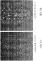
- FIG. 4 illustrates "pyramid levels," implemented by processing image frames with greater or lesser resolution.
- FIGs. 5A and 5B illustrate graphically, a depth map made by processing at pyramid level 2 versus level 1. In both cases, the depth map provides useful information, sufficient to enable a user to recognize an object being imaged. On recent smartphone generations, a pyramid level 1 is performing well to ensure a real-time operation.
- pyramid levels may be used depending on data rate, available processing and other factors.
- the pyramid level used may be predetermined, while in other embodiments, the pyramid level may be dynamically selected. For example, the pyramid level may be selected in some embodiments in proportion to the size of a queue of image frames waiting processing.
- Another alternative is that a certain minimum baseline needs to be available if comparing the angle of the latest image with the angle of the key frame.
- the data is integrated into a global map structure consisting of probabilistic point cloud data and camera poses.
- the data is added by an initial rigid alignment with the data from the previous key frame in the map.
- a loop-detection algorithm determines whether a loop-closing situation exists and triggers a global optimization that reduces the inconsistencies by spreading out the error. For this, first a global loop closing is performed on all the key frames with their corresponding relative pose. Then a global non-rigid registration is performed on all the depth data from all key frames which are residing in the global map. A non-rigid registration is performed to re-distribute the alignment error uniformly over the global map. By this, the depth data is deformed, by keeping the depth data of the key frames as rigid as possible.
- At act 1230 Based on the current view-point, a simple Poisson-based meshing is applied on the point cloud.
- the convex hull of the point cloud can be generated as a visualization strategy for feedback progress to the user.
- the projected texture of the mesh can be either simple uniform color, taken from the current viewpoint or done as a global texture map by using a Poisson-blending approach
- the rendered and textured mesh is superimposed on the viewfinder image and visualized to guide the user - areas with low/no depth confidence due to occlusions remain uncovered until a user moves the phone into a different position. Accordingly, it should be understood that confidence may be determined based on completeness of data, with a higher confidence being assigned to regions of an object for which there is adequate image data to compute a 3D model and a lower confidence being assigned to regions of an object for which the image data is not sufficient to compute a 3D model.
- confidence values may be determined such that higher confidence values are assigned when there are a sufficient number of image frames depicting a region to allow multiple independent calculations of the 3D model of a region and a confidence value may be assigned in proportion to the number of independent computations and/or percentage of such computations that yield consistent 3D models.
- confidence may be a metric computed quantitatively having a range of values, or may be a binary value, indicating that there is or is not sufficient data to compute a 3D depth map for a region of an object, or may have any other suitable form.
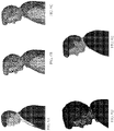
- FIGs. 6A-6E illustrate an exemplary process in which feedback is provided based on confidence of a 3D model.
- FIG. 6A represents a photograph of an object, here a person.
- Figure 6B represents an image that may be displayed through the viewfinder to guide the user early in the scanning process. This image may be displayed without color information. Also, as shown in figure 6B , portions of the image are shown as blotches, representing portions of the object for which there is inadequate depth information to render that portion of the image.
- Figure 6C represents a refined image that may be displayed at a later stage of the scanning process. The image of figure 6C may still be displayed without color information, reducing the amount of processing required to achieve that image. Figure 6C , however, has the blotchy portions of figure 6B replaced by depth information.
- Figure 6D represents the same object being imaged, with additional information, such as color, added to portions of the image.
- Figure 6E represents the finished image, including depth and other image information such as color, rendered from a 3-D model, which may then be used for other purposes.
- Key frames are stored with their associated probabilistic depth map information and camera information.
- JPEG EXIF headers may be used to store per view information.
- the depth map resolution can be equal or smaller than the resolution of the key frame.
- the following information can be stored in the EXIF header:
- This data allows for later post-processing operations and reconstruction with different algorithms in a portable and synchronized way.
- the final modeling is a post-processing step to the capturing which can be run in the background or on another processor.
- Post-processing may be used to attain higher resolution results by performing more computationally intensive meshing algorithms, 3D print-compatible meshing and texturing approaches. In contrast to the live-feedback, this not only takes the relevant views from a view-point into account, but performs a global mesh and texture.
- the following acts may be performed as part of this post-processing. These acts may be performed in the order listed or in any other suitable order:
- a merge of scan with a high-resolution template model can be conducted.
- FIGs. 7A-7C illustrate an example of such processing.
- FIG. 7A depicts a template model - in this case a model of a human.
- This model may be used to add information to a three-dimensional model developed by scanning a person to acquire three-dimensional information using image frames in a sequence.
- the template model may include features of the human, such as arms, hands, fingers, legs, a face, eyes, and a mouth. These features of the human may be used to attach additional information to the 3-D model being developed. For example, surfaces in the 3D model that, according to the template model, represent skin may be colored with flesh tones. Likewise, portions that correspond to clothes may be depicted with texture of cloth or even overlaid with image information depicting clothes.
- FIG. 7C illustrates an example of how image information may be overlaid on the model.
- the template model has been used to identify a portion of the 3D model representing the face of the person being imaged. An image of the person's face is then overlaid on that portion of the 3D model, producing a more realistic model of the actual portion whose image was 3D image was captured using techniques as described above.
- Configuration might include the following options:
- the result can be also used in video games as 3D playable avatars due to the rigged model.
- a smart phone or other portable electronic device may sensors such as a global positioning system (GPS) to sense location.
- GPS global positioning system
- Processing as described herein may be implemented as an application executing on an operating system.
- the operating system may include utilities to control the camera, sensors and other hardware to capture data from them and make it available to the application executing on the computing device.
- interactions with the hardware elements may be controlled by custom software loaded on the device.
- a computing device may include a network interface to implement a personal area network or to connect to a LAN or WAN such that data, and in some embodiments processing load, may be shared with other devices.
- a network interface may operate in accordance with any suitable technology, including a Bluetooth, Zigbee or an 802.11 ad hoc mode, for example.
- the system may use fast features and edgelets for feature and patch extraction in block [1212].
- the system may use, in addition to fast features and edgelets, stronger features for places with a small density of feature distribution in block [1212].
- the system captures an image frame and inertia information associated with movement of the portable electronic device correlated in time.
- This information may be provided for processing as a package with timestamps which are synchronized such that they can be associated to each other using a shared clock.
- the system uses the image sequence from prior to the key frame for refinement of the probabilistic depth information.
- the system is using every image frame as a key frame and therefore providing a continuous stream of probabilistic depth maps, by reusing computational expensive operations and by reusing intermediate results from the previous calculations.
- the system is determining whether relocalization is required and in that case tries to recover from this state by searching the full map to find the current pose.
- techniques as described herein may be used for tracking and 3D sensing for Virtual Reality headsets.
- a smartphone is used as an example of a portable electronic device that may be used to capture and/or process image frames, other electronic devices may be used for either or both of these functions.
- the system is mounted on a virtual reality or augmented reality headset and can use several independent cameras to cover a full 360 view.
- techniques as described herein may be applied in any application in which it is desirable to merge and configuring image information.
- the techniques may be used to create photorealistic 3D printable avatars based on partial scan data on smartphones.
- a system and method for creating and configuring 3D printable figurines of people is presented. Such a system may merge a scan of a user or other person's face, head or body with a specifically annotated high resolution and 3D print-ready mesh of a person. The scan of the user might be done with a user or world-facing camera of a smartphone.
- the whole process can run locally on a mobile handheld device due to space efficient and annotated template models and smart merging algorithms.
- the merging template uses a graph-cut approach to ensure seamless texture and geometry synthesis.
- the merging template uses defined & fixed merging regions.
- the merging template contains a fully rigged motion skeleton to which also the scan data is attached thus enabling to easily generate new poses, facial expressions, or animation of the final avatar.
- the generated 3D character becomes instantly playable in video games.
- a video game processor for example, in which the output of a processor processing image frames as described herein is supplied to the video game processor.
- the video game processor may be programmed to use the output of the image frame processing to render an avatar within the game - allowing a user to place themselves or any other person in the game by scanning themselves.
- the merging template contains defined docking points for configuring clothing or accessories.
- the merging template contains annotations for aligning the newly created avatar with a second figurine and changing text or textures on both figurines.
- the configurator includes custom floor plates, backdrops, regions for custom text.
- the 3D printability (e.g. too thin areas, not stable enough, bad center of gravity, etc) is visualized immediately with color flags while changing configuration options.
- the embodiments can be implemented in any of numerous ways.
- the embodiments may be implemented using hardware, software or a combination thereof.
- the software code can be executed on any suitable processor or collection of processors, whether provided in a single computer or distributed among multiple computers.
- processors may be implemented as integrated circuits, with one or more processors in an integrated circuit component, including commercially available integrated circuit components known in the art by names such as CPU chips, GPU chips, microprocessor, microcontroller, or co-processor.
- a processor may be implemented in custom circuitry, such as an ASIC, or semicustom circuitry resulting from configuring a programmable logic device.
- a processor may be a portion of a larger circuit or semiconductor device, whether commercially available, semi-custom or custom.
- some commercially available microprocessors have multiple cores such that one or a subset of those cores may constitute a processor.
- a processor may be implemented using circuitry in any suitable format.
- a computer may be embodied in any of a number of forms, such as a rack-mounted computer, a desktop computer, a laptop computer, or a tablet computer. Additionally, a computer may be embedded in a device not generally regarded as a computer but with suitable processing capabilities, including a Personal Digital Assistant (PDA), a smart phone or any other suitable portable or fixed electronic device.
- PDA Personal Digital Assistant
- a computer may have one or more input and output devices. These devices can be used, among other things, to present a user interface. Examples of output devices that can be used to provide a user interface include printers or display screens for visual presentation of output and speakers or other sound generating devices for audible presentation of output. Examples of input devices that can be used for a user interface include keyboards, and pointing devices, such as mice, touch pads, and digitizing tablets. As another example, a computer may receive input information through speech recognition or in other audible format. In the embodiment illustrated, the input/output devices are illustrated as physically separate from the computing device. In some embodiments, however, the input and/or output devices may be physically integrated into the same unit as the processor or other elements of the computing device. For example, a keyboard might be implemented as a soft keyboard on a touch screen. Alternatively, the input/output devices may be entirely disconnected from the computing device, and functionally integrated through a wireless connection.
- Such computers may be interconnected by one or more networks in any suitable form, including as a local area network or a wide area network, such as an enterprise network or the Internet.
- networks may be based on any suitable technology and may operate according to any suitable protocol and may include wireless networks, wired networks or fiber optic networks.
- the various methods or processes outlined herein may be coded as software that is executable on one or more processors that employ any one of a variety of operating systems or platforms. Additionally, such software may be written using any of a number of suitable programming languages and/or programming or scripting tools, and also may be compiled as executable machine language code or intermediate code that is executed on a framework or virtual machine.
- the invention may be embodied as a computer readable storage medium (or multiple computer readable media) (e.g., a computer memory, one or more floppy discs, compact discs (CD), optical discs, digital video disks (DVD), magnetic tapes, flash memories, circuit configurations in Field Programmable Gate Arrays or other semiconductor devices, or other tangible computer storage medium) encoded with one or more programs that, when executed on one or more computers or other processors, perform methods that implement the various embodiments of the invention discussed above.
- a computer readable storage medium may retain information for a sufficient time to provide computer-executable instructions in a non-transitory form.
- Such a computer readable storage medium or media can be transportable, such that the program or programs stored thereon can be loaded onto one or more different computers or other processors to implement various aspects of the present invention as discussed above.
- the term "computer-readable storage medium” encompasses only a computer-readable medium that can be considered to be a manufacture (i.e., article of manufacture) or a machine.
- the invention may be embodied as a computer readable medium other than a computer-readable storage medium, such as a propagating signal.
- program or “software” are used herein in a generic sense to refer to any type of computer code or set of computer-executable instructions that can be employed to program a computer or other processor to implement various aspects of the present invention as discussed above. Additionally, it should be appreciated that according to one aspect of this embodiment, one or more computer programs that when executed perform methods of the present invention need not reside on a single computer or processor, but may be distributed in a modular fashion amongst a number of different computers or processors to implement various aspects of the present invention.
- Computer-executable instructions may be in many forms, such as program modules, executed by one or more computers or other devices.
- program modules include routines, programs, objects, components, data structures, etc. that perform particular tasks or implement particular abstract data types.
- functionality of the program modules may be combined or distributed as desired in various embodiments.
- data structures may be stored in computer-readable media in any suitable form.
- data structures may be shown to have fields that are related through location in the data structure. Such relationships may likewise be achieved by assigning storage for the fields with locations in a computer-readable medium that conveys relationship between the fields.
- any suitable mechanism may be used to establish a relationship between information in fields of a data structure, including through the use of pointers, tags or other mechanisms that establish relationship between data elements.
- the invention may be embodied as a method, of which an example has been provided.
- the acts performed as part of the method may be ordered in any suitable way. Accordingly, embodiments may be constructed in which acts are performed in an order different than illustrated, which may include performing some acts simultaneously, even though shown as sequential acts in illustrative embodiments.
- the invention may relate to one or more of the following items:
Landscapes
- Engineering & Computer Science (AREA)
- Physics & Mathematics (AREA)
- Theoretical Computer Science (AREA)
- General Physics & Mathematics (AREA)
- Geometry (AREA)
- Computer Graphics (AREA)
- Computer Vision & Pattern Recognition (AREA)
- Software Systems (AREA)
- Computing Systems (AREA)
- Processing Or Creating Images (AREA)
- Studio Devices (AREA)
- Image Analysis (AREA)
- Image Generation (AREA)
Applications Claiming Priority (3)
| Application Number | Priority Date | Filing Date | Title |
|---|---|---|---|
| US201562273821P | 2015-12-31 | 2015-12-31 | |
| EP16847598.6A EP3398168B1 (fr) | 2015-12-31 | 2016-12-30 | Procédé et dispositif pour capture 3d en temps réel et rétroaction en direct avec des caméras monoculaires |
| PCT/IB2016/001985 WO2017115149A1 (fr) | 2015-12-31 | 2016-12-30 | Procédé et système pour capture 3d en temps réel et rétroaction en direct avec des caméras monoculaires |
Related Parent Applications (1)
| Application Number | Title | Priority Date | Filing Date |
|---|---|---|---|
| EP16847598.6A Division EP3398168B1 (fr) | 2015-12-31 | 2016-12-30 | Procédé et dispositif pour capture 3d en temps réel et rétroaction en direct avec des caméras monoculaires |
Publications (1)
| Publication Number | Publication Date |
|---|---|
| EP4053795A1 true EP4053795A1 (fr) | 2022-09-07 |
Family
ID=58358751
Family Applications (2)
| Application Number | Title | Priority Date | Filing Date |
|---|---|---|---|
| EP16847598.6A Active EP3398168B1 (fr) | 2015-12-31 | 2016-12-30 | Procédé et dispositif pour capture 3d en temps réel et rétroaction en direct avec des caméras monoculaires |
| EP22167743.8A Pending EP4053795A1 (fr) | 2015-12-31 | 2016-12-30 | Procédé et système pour capture 3d en temps réel et rétroaction en direct avec des caméras monoculaires |
Family Applications Before (1)
| Application Number | Title | Priority Date | Filing Date |
|---|---|---|---|
| EP16847598.6A Active EP3398168B1 (fr) | 2015-12-31 | 2016-12-30 | Procédé et dispositif pour capture 3d en temps réel et rétroaction en direct avec des caméras monoculaires |
Country Status (6)
| Country | Link |
|---|---|
| US (1) | US11631213B2 (fr) |
| EP (2) | EP3398168B1 (fr) |
| JP (2) | JP6934887B2 (fr) |
| KR (1) | KR20180121494A (fr) |
| CN (2) | CN109074660B (fr) |
| WO (1) | WO2017115149A1 (fr) |
Families Citing this family (25)
| Publication number | Priority date | Publication date | Assignee | Title |
|---|---|---|---|---|
| WO2019164500A1 (fr) * | 2018-02-23 | 2019-08-29 | Sony Mobile Communications Inc. | Procédés de modélisation d'un objet 3d, et dispositifs et produits programmes d'ordinateur associés |
| WO2019164502A1 (fr) * | 2018-02-23 | 2019-08-29 | Sony Mobile Communications Inc. | Procédés, dispositifs et produits programme informatique permettant de générer des modèles 3d |
| US10510178B2 (en) * | 2018-02-27 | 2019-12-17 | Verizon Patent And Licensing Inc. | Methods and systems for volumetric reconstruction based on a confidence field |
| JP6511681B1 (ja) * | 2018-10-15 | 2019-05-15 | 株式会社Mujin | 形状情報生成装置、制御装置、積み降ろし装置、物流システム、プログラム、及び、制御方法 |
| CN109697733A (zh) * | 2018-12-26 | 2019-04-30 | 广州文远知行科技有限公司 | 点云空间寻点方法、装置、计算机设备和存储介质 |
| CN109675315B (zh) * | 2018-12-27 | 2021-01-26 | 网易(杭州)网络有限公司 | 游戏角色模型的生成方法、装置、处理器及终端 |
| KR20200086815A (ko) | 2019-01-10 | 2020-07-20 | 삼성전기주식회사 | 카메라 모듈 |
| US20220084286A1 (en) * | 2019-01-11 | 2022-03-17 | Hewlett-Packard Development Company, L.P. | Optimized mesh representations |
| US11783443B2 (en) | 2019-01-22 | 2023-10-10 | Fyusion, Inc. | Extraction of standardized images from a single view or multi-view capture |
| US10887582B2 (en) | 2019-01-22 | 2021-01-05 | Fyusion, Inc. | Object damage aggregation |
| US11176704B2 (en) * | 2019-01-22 | 2021-11-16 | Fyusion, Inc. | Object pose estimation in visual data |
| WO2020161316A1 (fr) * | 2019-02-09 | 2020-08-13 | Naked Labs Austria Gmbh | Balayage corporel passif |
| CN111696144B (zh) * | 2019-03-11 | 2024-06-25 | 北京地平线机器人技术研发有限公司 | 深度信息确定方法、深度信息确定装置及电子设备 |
| US11004230B2 (en) | 2019-03-22 | 2021-05-11 | Microsoft Technology Licensing, Llc | Predicting three-dimensional articulated and target object pose |
| WO2020250726A1 (fr) * | 2019-06-14 | 2020-12-17 | ソニー株式会社 | Dispositif de traitement d'image et procédé de traitement d'image |
| CN110490222B (zh) * | 2019-07-05 | 2022-11-04 | 广东工业大学 | 一种基于低性能处理器设备的半直接视觉定位方法 |
| CN110544294B (zh) * | 2019-07-16 | 2023-09-01 | 深圳进化动力数码科技有限公司 | 一种基于全景视频的稠密三维重构方法 |
| US11620779B2 (en) * | 2020-01-03 | 2023-04-04 | Vangogh Imaging, Inc. | Remote visualization of real-time three-dimensional (3D) facial animation with synchronized voice |
| US11776142B2 (en) | 2020-01-16 | 2023-10-03 | Fyusion, Inc. | Structuring visual data |
| US11562474B2 (en) | 2020-01-16 | 2023-01-24 | Fyusion, Inc. | Mobile multi-camera multi-view capture |
| US11341719B2 (en) | 2020-05-07 | 2022-05-24 | Toyota Research Institute, Inc. | System and method for estimating depth uncertainty for self-supervised 3D reconstruction |
| US11361495B1 (en) * | 2021-01-27 | 2022-06-14 | Beijing Wodong Tianjun Information Technology Co., Ltd. | System and method for texture mapping based on guidance prior |
| US11605151B2 (en) | 2021-03-02 | 2023-03-14 | Fyusion, Inc. | Vehicle undercarriage imaging |
| WO2022194939A1 (fr) * | 2021-03-16 | 2022-09-22 | forty2 Technologies GmbH | Détection de défauts de fabrication dans l'impression 3d |
| EP4318390A1 (fr) | 2021-03-23 | 2024-02-07 | NEC Corporation | Système de gestion d'entrée/sortie, procédé de gestion d'entrée/sortie et support d'enregistrement |
Citations (15)
| Publication number | Priority date | Publication date | Assignee | Title |
|---|---|---|---|---|
| US20040041804A1 (en) | 2000-03-08 | 2004-03-04 | Ives John D. | Apparatus and method for generating a three-dimensional representation from a two-dimensional image |
| US20060003111A1 (en) | 2004-07-01 | 2006-01-05 | Tan Tseng | System and method for creating a 3D figurine using 2D and 3D image capture |
| US7103211B1 (en) | 2001-09-04 | 2006-09-05 | Geometrix, Inc. | Method and apparatus for generating 3D face models from one camera |
| WO2007084589A2 (fr) * | 2006-01-20 | 2007-07-26 | 3M Innovative Properties Company | Récupération de données par balayage en trois dimensions |
| US20090066693A1 (en) | 2007-09-06 | 2009-03-12 | Roc Carson | Encoding A Depth Map Into An Image Using Analysis Of Two Consecutive Captured Frames |
| US8243123B1 (en) | 2005-02-02 | 2012-08-14 | Geshwind David M | Three-dimensional camera adjunct |
| US20130307848A1 (en) | 2012-05-17 | 2013-11-21 | Disney Enterprises, Inc. | Techniques for processing reconstructed three-dimensional image data |
| US20130329020A1 (en) * | 2011-02-22 | 2013-12-12 | 3M Innovative Properties Company | Hybrid stitching |
| US8655094B2 (en) | 2011-05-11 | 2014-02-18 | The United States Of America As Represented By The Administrator Of The National Aeronautics And Space Administration | Photogrammetry system and method for determining relative motion between two bodies |
| US8659596B2 (en) | 2008-11-24 | 2014-02-25 | Mixamo, Inc. | Real time generation of animation-ready 3D character models |
| WO2014092740A1 (fr) | 2012-12-15 | 2014-06-19 | Daniel Lauer | Système et procédés de capture à utiliser pour créer des modèles 3d d'objets |
| WO2014191055A1 (fr) * | 2013-05-31 | 2014-12-04 | Longsand Limited | Modélisation d'objets tridimensionnels |
| US8982122B2 (en) | 2008-11-24 | 2015-03-17 | Mixamo, Inc. | Real time concurrent design of shape, texture, and motion for 3D character animation |
| EP2851868A1 (fr) * | 2013-09-20 | 2015-03-25 | ETH Zurich | Reconstruction 3D |
| WO2015173173A1 (fr) | 2014-05-12 | 2015-11-19 | Dacuda Ag | Procédé et appareil pour balayer et imprimer un objet tridimensionnel (3d) |
Family Cites Families (24)
| Publication number | Priority date | Publication date | Assignee | Title |
|---|---|---|---|---|
| US6333749B1 (en) * | 1998-04-17 | 2001-12-25 | Adobe Systems, Inc. | Method and apparatus for image assisted modeling of three-dimensional scenes |
| US6269175B1 (en) * | 1998-08-28 | 2001-07-31 | Sarnoff Corporation | Method and apparatus for enhancing regions of aligned images using flow estimation |
| EP1418766A3 (fr) * | 1998-08-28 | 2010-03-24 | Imax Corporation | Verfahren und Gerät zur Verarbeitung von Bildern |
| US9286941B2 (en) * | 2001-05-04 | 2016-03-15 | Legend3D, Inc. | Image sequence enhancement and motion picture project management system |
| US8401336B2 (en) * | 2001-05-04 | 2013-03-19 | Legend3D, Inc. | System and method for rapid image sequence depth enhancement with augmented computer-generated elements |
| JP2004077221A (ja) | 2002-08-13 | 2004-03-11 | Fujitsu Ltd | 画像計測プログラム |
| US9300834B2 (en) | 2009-05-20 | 2016-03-29 | Dacuda Ag | Image processing for handheld scanner |
| US8582182B2 (en) | 2009-05-20 | 2013-11-12 | Dacuda Ag | Automatic sizing of images acquired by a handheld scanner |
| US8339467B2 (en) | 2010-03-25 | 2012-12-25 | Dacuda Ag | Synchronization of navigation and image information for handheld scanner |
| JP5182229B2 (ja) | 2009-06-02 | 2013-04-17 | ソニー株式会社 | 画像処理装置、画像処理方法及びプログラム |
| US9019349B2 (en) * | 2009-07-31 | 2015-04-28 | Naturalpoint, Inc. | Automated collective camera calibration for motion capture |
| JP4978941B2 (ja) | 2009-10-16 | 2012-07-18 | エリヤ株式会社 | 三次元モデリング装置及び方法並びにプログラム |
| US8570320B2 (en) | 2011-01-31 | 2013-10-29 | Microsoft Corporation | Using a three-dimensional environment model in gameplay |
| WO2013054240A1 (fr) | 2011-10-10 | 2013-04-18 | Koninklijke Philips Electronics N.V. | Traitement d'une carte de profondeur |
| US9117267B2 (en) * | 2012-10-18 | 2015-08-25 | Google Inc. | Systems and methods for marking images for three-dimensional image generation |
| US9269012B2 (en) | 2013-08-22 | 2016-02-23 | Amazon Technologies, Inc. | Multi-tracker object tracking |
| EP3039617B1 (fr) | 2013-08-31 | 2020-05-20 | ML Netherlands C.V. | Réaction envoyée à un utilisateur pour un contrôle et une amélioration en temps réel de la qualité d'une image numérisée |
| WO2015082572A2 (fr) | 2013-12-03 | 2015-06-11 | Dacuda Ag | Réaction d'un utilisateur pour un contrôle et une amélioration en temps réel de la qualité d'une image analysée |
| EP3092790B1 (fr) | 2014-01-07 | 2020-07-29 | ML Netherlands C.V. | Commande adaptative de caméra pour réduire le flou de mouvement pendant une capture d'images en temps réel |
| US10410321B2 (en) | 2014-01-07 | 2019-09-10 | MN Netherlands C.V. | Dynamic updating of a composite image |
| US10055876B2 (en) * | 2014-06-06 | 2018-08-21 | Matterport, Inc. | Optimal texture memory allocation |
| US10574974B2 (en) * | 2014-06-27 | 2020-02-25 | A9.Com, Inc. | 3-D model generation using multiple cameras |
| US9607388B2 (en) | 2014-09-19 | 2017-03-28 | Qualcomm Incorporated | System and method of pose estimation |
| CN104599284B (zh) * | 2015-02-15 | 2017-06-13 | 四川川大智胜软件股份有限公司 | 基于多视角手机自拍图像的三维人脸重建方法 |
-
2016
- 2016-12-30 EP EP16847598.6A patent/EP3398168B1/fr active Active
- 2016-12-30 JP JP2018553329A patent/JP6934887B2/ja active Active
- 2016-12-30 CN CN201680082863.5A patent/CN109074660B/zh active Active
- 2016-12-30 US US16/067,210 patent/US11631213B2/en active Active
- 2016-12-30 CN CN202210305542.4A patent/CN115359207A/zh active Pending
- 2016-12-30 EP EP22167743.8A patent/EP4053795A1/fr active Pending
- 2016-12-30 KR KR1020187021986A patent/KR20180121494A/ko not_active Application Discontinuation
- 2016-12-30 WO PCT/IB2016/001985 patent/WO2017115149A1/fr active Application Filing
-
2021
- 2021-08-24 JP JP2021136196A patent/JP7249390B2/ja active Active
Patent Citations (15)
| Publication number | Priority date | Publication date | Assignee | Title |
|---|---|---|---|---|
| US20040041804A1 (en) | 2000-03-08 | 2004-03-04 | Ives John D. | Apparatus and method for generating a three-dimensional representation from a two-dimensional image |
| US7103211B1 (en) | 2001-09-04 | 2006-09-05 | Geometrix, Inc. | Method and apparatus for generating 3D face models from one camera |
| US20060003111A1 (en) | 2004-07-01 | 2006-01-05 | Tan Tseng | System and method for creating a 3D figurine using 2D and 3D image capture |
| US8243123B1 (en) | 2005-02-02 | 2012-08-14 | Geshwind David M | Three-dimensional camera adjunct |
| WO2007084589A2 (fr) * | 2006-01-20 | 2007-07-26 | 3M Innovative Properties Company | Récupération de données par balayage en trois dimensions |
| US20090066693A1 (en) | 2007-09-06 | 2009-03-12 | Roc Carson | Encoding A Depth Map Into An Image Using Analysis Of Two Consecutive Captured Frames |
| US8659596B2 (en) | 2008-11-24 | 2014-02-25 | Mixamo, Inc. | Real time generation of animation-ready 3D character models |
| US8982122B2 (en) | 2008-11-24 | 2015-03-17 | Mixamo, Inc. | Real time concurrent design of shape, texture, and motion for 3D character animation |
| US20130329020A1 (en) * | 2011-02-22 | 2013-12-12 | 3M Innovative Properties Company | Hybrid stitching |
| US8655094B2 (en) | 2011-05-11 | 2014-02-18 | The United States Of America As Represented By The Administrator Of The National Aeronautics And Space Administration | Photogrammetry system and method for determining relative motion between two bodies |
| US20130307848A1 (en) | 2012-05-17 | 2013-11-21 | Disney Enterprises, Inc. | Techniques for processing reconstructed three-dimensional image data |
| WO2014092740A1 (fr) | 2012-12-15 | 2014-06-19 | Daniel Lauer | Système et procédés de capture à utiliser pour créer des modèles 3d d'objets |
| WO2014191055A1 (fr) * | 2013-05-31 | 2014-12-04 | Longsand Limited | Modélisation d'objets tridimensionnels |
| EP2851868A1 (fr) * | 2013-09-20 | 2015-03-25 | ETH Zurich | Reconstruction 3D |
| WO2015173173A1 (fr) | 2014-05-12 | 2015-11-19 | Dacuda Ag | Procédé et appareil pour balayer et imprimer un objet tridimensionnel (3d) |
Non-Patent Citations (20)
| Title |
|---|
| BARAN, I.POPOVIC, J.: "Automatic rigging and animation of 3D characters", ACM TOG, vol. 26, 2007, pages 1 - 8 |
| BLANZ, V.VETTER, T.: "A morphable model for the synthesis of 3D faces", PROCEEDINGS OF THE 26TH ANNUAL CONFERENCE ON COMPUTER GRAPHICS AND INTERACTIVE TECHNIQUES - SIGGRAPH '99, 1999, pages 187 - 194, XP001032901, DOI: 10.1145/311535.311556 |
| CURLESS, B.: "From range scans to 3D models", ACM SIGGRAPH COMPUTER GRAPHICS, vol. 33, no. 4, 1999, pages 38 - 41, XP000908617, DOI: 10.1145/345370.345399 |
| FAESSLER, M.FONTANA, F.FORSTER, C.MUEGGLER, E.PIZZOLI, M.SCARAMUZZA, D.: "Autonomous, Vision-based Flight and Live Dense 3D Mapping with a Quadrotor Micro Aerial Vehicle", JOURNAL OF FIELD ROBOTICS, 2015 |
| FORSTER, C. ET AL.: "Collaborative monocular SLAM with multiple Micro Aerial Vehicles", IEEE INTERNATIONAL CONFERENCE ON INTELLIGENT ROBOTS AND SYSTEMS, vol. 143607, no. 200021, 2013, pages 3963 - 3970 |
| FORSTER, C. ET AL.: "Continuous On-Board Monocular-Vision - based Elevation Mapping Applied to Autonomous Landing of Micro Aerial Vehicles", IEEE INTERNATIONAL CONFERENCE ON ROBOTICS AND AUTOMATION (ICRA), 2015 |
| FORSTER, C.CARLONE, L.: "IMU Preintegration on Manifold for Efficient Visual-Inertial Maximum-a-Posteriori Estimation", ROBOTICS, 2015 |
| FORSTER, C.PIZZOLI, M.SCARAMUZZA, D., SVO: FAST SEMI-DIRECT MONOCULAR VISUAL ODOMETRY, 2014 |
| HIRSHBERG, D. ET AL.: "Coregistration: Simultaneous alignment and modeling of articulated 3D shape", LECTURE NOTES IN COMPUTER SCIENCE (INCLUDING SUBSERIES LECTURE NOTES IN ARTIFICIAL INTELLIGENCE AND LECTURE NOTES IN BIOINFORMATICS), 7577 LNCS(PART 6, 2012, pages 242 - 255, XP047019085, DOI: 10.1007/978-3-642-33783-3_18 |
| LANMAN, D.TAUBIN, G.: "Build Your Own 3D Scanner : 3D Photography for Beginners", ACM SIGGRAPH 2009 COURSES, 2009, pages 94 |
| LI, H. ET AL.: "3D self-portraits", ACM TRANSACTIONS ON GRAPHICS, vol. 32, 2013, pages 1 - 9, XP058033902, DOI: 10.1145/2508363.2508407 |
| MAJDIK, A.L. ET AL.: "Micro air vehicle localization and position tracking from textured 3D cadastral models", 2014 IEEE INTERNATIONAL CONFERENCE ON ROBOTICS AND AUTOMATION (ICRA), 2014, pages 920 - 927, XP032650685, DOI: 10.1109/ICRA.2014.6906964 |
| PIZZOLI, M.FORSTER, C.SCARAMUZZA, D.: "REMODE : Probabilistic , Monocular Dense Reconstruction in Real Time", PROC. IEEE INTERNATIONAL CONFERENCE ON ROBOTICS AND AUTOMATION (ICRA), 2014, pages 2609 - 2616, XP032650817, DOI: 10.1109/ICRA.2014.6907233 |
| SAURER, 0.POLLEFEYS, M.LEE, G.H., A MINIMAL SOLUTION TO THE ROLLING SHUTTER POSE ESTIMATION PROBLEM |
| TANSKANEN, P. ET AL., SEMI-DIRECT EKF-BASED MONOCULAR VISUAL-INERTIAL ODOMETRY |
| TANSKANEN, P. ET AL.: "Live Metric 3D Reconstruction on Mobile Phones", 2013 IEEE INTERNATIONAL CONFERENCE ON COMPUTER VISION, 2013, pages 65 - 72, XP032572748, DOI: 10.1109/ICCV.2013.15 |
| VLASIC, D. ET AL.: "Dynamic shape capture using multi-view photometric stereo", ACM TRANSACTIONS ON GRAPHICS, vol. 28, 2009, pages l |
| WEISE, T. ET AL.: "Online loop closure for real-time interactive 3D scanning", COMPUTER VISION AND IMAGE UNDERSTANDING, vol. 115, no. 5, 2011, pages 635 - 648, XP055120146, DOI: 10.1016/j.cviu.2010.11.023 |
| WEISE, T.LI, H. ET AL.: "Face/Off", PROCEEDINGS OF THE 2009 ACM SIGGRAPH/EUROGRAPHICS SYMPOSIUM ON COMPUTER ANIMATION - SCA '09, 2009, pages 7, XP058174994, DOI: 10.1145/1599470.1599472 |
| WEISE, T.WISMER, T. ET AL.: "In-hand scanning with online loop closure", 2009 IEEE 12TH INTERNATIONAL CONFERENCE ON COMPUTER VISION WORKSHOPS, ICCV WORKSHOPS 2009, 2009, pages 1630 - 1637, XP031664509 |
Also Published As
| Publication number | Publication date |
|---|---|
| JP2021192250A (ja) | 2021-12-16 |
| CN115359207A (zh) | 2022-11-18 |
| WO2017115149A1 (fr) | 2017-07-06 |
| JP6934887B2 (ja) | 2021-09-15 |
| EP3398168A1 (fr) | 2018-11-07 |
| JP7249390B2 (ja) | 2023-03-30 |
| EP3398168B1 (fr) | 2022-04-13 |
| CN109074660B (zh) | 2022-04-12 |
| KR20180121494A (ko) | 2018-11-07 |
| US11631213B2 (en) | 2023-04-18 |
| JP2019501473A (ja) | 2019-01-17 |
| US20210209835A1 (en) | 2021-07-08 |
| CN109074660A (zh) | 2018-12-21 |
Similar Documents
| Publication | Publication Date | Title |
|---|---|---|
| EP3398168B1 (fr) | Procédé et dispositif pour capture 3d en temps réel et rétroaction en direct avec des caméras monoculaires | |
| US11948376B2 (en) | Method, system, and device of generating a reduced-size volumetric dataset | |
| US10529137B1 (en) | Machine learning systems and methods for augmenting images | |
| CN109636831B (zh) | 一种估计三维人体姿态及手部信息的方法 | |
| EP2880633B1 (fr) | Animation d'objets utilisant le corps humain | |
| Muratov et al. | 3DCapture: 3D Reconstruction for a Smartphone | |
| Li et al. | 3D human pose and shape estimation through collaborative learning and multi-view model-fitting | |
| US11688136B2 (en) | 3D object model reconstruction from 2D images | |
| Ye et al. | Free-viewpoint video of human actors using multiple handheld kinects | |
| US10885708B2 (en) | Automated costume augmentation using shape estimation | |
| US20230267687A1 (en) | 3d object model reconstruction from 2d images | |
| WO2022143390A1 (fr) | Système et procédé d'essayage 3d basé sur une pose humaine et une estimation de la forme du corps | |
| Ravikumar | Lightweight markerless monocular face capture with 3d spatial priors | |
| US20240020901A1 (en) | Method and application for animating computer generated images | |
| Zhou et al. | Tracking of Deformable Human Avatars through Fusion of Low-Dimensional 2D and 3D Kinematic Models | |
| Pilet | Augmented reality for non-rigid surfaces. | |
| Magnor | Reconstructing 3D Human Avatars from Monocular Images | |
| Xiong | Automatic 3D human modeling: an initial stage towards 2-way inside interaction in mixed reality | |
| Nasir | Fast 3D Reconstruction of Human Figures in Motion | |
| Wu | Inverse rendering for scene reconstruction in general environments |
Legal Events
| Date | Code | Title | Description |
|---|---|---|---|
| PUAI | Public reference made under article 153(3) epc to a published international application that has entered the european phase |
Free format text: ORIGINAL CODE: 0009012 |
|
| STAA | Information on the status of an ep patent application or granted ep patent |
Free format text: STATUS: THE APPLICATION HAS BEEN PUBLISHED |
|
| AC | Divisional application: reference to earlier application |
Ref document number: 3398168 Country of ref document: EP Kind code of ref document: P |
|
| AK | Designated contracting states |
Kind code of ref document: A1 Designated state(s): AL AT BE BG CH CY CZ DE DK EE ES FI FR GB GR HR HU IE IS IT LI LT LU LV MC MK MT NL NO PL PT RO RS SE SI SK SM TR |
|
| STAA | Information on the status of an ep patent application or granted ep patent |
Free format text: STATUS: REQUEST FOR EXAMINATION WAS MADE |
|
| 17P | Request for examination filed |
Effective date: 20230303 |
|
| RBV | Designated contracting states (corrected) |
Designated state(s): AL AT BE BG CH CY CZ DE DK EE ES FI FR GB GR HR HU IE IS IT LI LT LU LV MC MK MT NL NO PL PT RO RS SE SI SK SM TR |