EP4053589A1 - Electro-optical distance meter and method for calculating optical noise signal - Google Patents
Electro-optical distance meter and method for calculating optical noise signal Download PDFInfo
- Publication number
- EP4053589A1 EP4053589A1 EP22159785.9A EP22159785A EP4053589A1 EP 4053589 A1 EP4053589 A1 EP 4053589A1 EP 22159785 A EP22159785 A EP 22159785A EP 4053589 A1 EP4053589 A1 EP 4053589A1
- Authority
- EP
- European Patent Office
- Prior art keywords
- measuring
- light
- noise signal
- distance
- adjusting means
- Prior art date
- Legal status (The legal status is an assumption and is not a legal conclusion. Google has not performed a legal analysis and makes no representation as to the accuracy of the status listed.)
- Granted
Links
Images







Classifications
-
- G—PHYSICS
- G01—MEASURING; TESTING
- G01S—RADIO DIRECTION-FINDING; RADIO NAVIGATION; DETERMINING DISTANCE OR VELOCITY BY USE OF RADIO WAVES; LOCATING OR PRESENCE-DETECTING BY USE OF THE REFLECTION OR RERADIATION OF RADIO WAVES; ANALOGOUS ARRANGEMENTS USING OTHER WAVES
- G01S7/00—Details of systems according to groups G01S13/00, G01S15/00, G01S17/00
- G01S7/48—Details of systems according to groups G01S13/00, G01S15/00, G01S17/00 of systems according to group G01S17/00
- G01S7/497—Means for monitoring or calibrating
-
- G—PHYSICS
- G01—MEASURING; TESTING
- G01S—RADIO DIRECTION-FINDING; RADIO NAVIGATION; DETERMINING DISTANCE OR VELOCITY BY USE OF RADIO WAVES; LOCATING OR PRESENCE-DETECTING BY USE OF THE REFLECTION OR RERADIATION OF RADIO WAVES; ANALOGOUS ARRANGEMENTS USING OTHER WAVES
- G01S7/00—Details of systems according to groups G01S13/00, G01S15/00, G01S17/00
- G01S7/48—Details of systems according to groups G01S13/00, G01S15/00, G01S17/00 of systems according to group G01S17/00
- G01S7/491—Details of non-pulse systems
- G01S7/4912—Receivers
- G01S7/4917—Receivers superposing optical signals in a photodetector, e.g. optical heterodyne detection
-
- G—PHYSICS
- G01—MEASURING; TESTING
- G01S—RADIO DIRECTION-FINDING; RADIO NAVIGATION; DETERMINING DISTANCE OR VELOCITY BY USE OF RADIO WAVES; LOCATING OR PRESENCE-DETECTING BY USE OF THE REFLECTION OR RERADIATION OF RADIO WAVES; ANALOGOUS ARRANGEMENTS USING OTHER WAVES
- G01S17/00—Systems using the reflection or reradiation of electromagnetic waves other than radio waves, e.g. lidar systems
- G01S17/02—Systems using the reflection of electromagnetic waves other than radio waves
- G01S17/06—Systems determining position data of a target
- G01S17/08—Systems determining position data of a target for measuring distance only
- G01S17/32—Systems determining position data of a target for measuring distance only using transmission of continuous waves, whether amplitude-, frequency-, or phase-modulated, or unmodulated
- G01S17/34—Systems determining position data of a target for measuring distance only using transmission of continuous waves, whether amplitude-, frequency-, or phase-modulated, or unmodulated using transmission of continuous, frequency-modulated waves while heterodyning the received signal, or a signal derived therefrom, with a locally-generated signal related to the contemporaneously transmitted signal
-
- G—PHYSICS
- G01—MEASURING; TESTING
- G01S—RADIO DIRECTION-FINDING; RADIO NAVIGATION; DETERMINING DISTANCE OR VELOCITY BY USE OF RADIO WAVES; LOCATING OR PRESENCE-DETECTING BY USE OF THE REFLECTION OR RERADIATION OF RADIO WAVES; ANALOGOUS ARRANGEMENTS USING OTHER WAVES
- G01S7/00—Details of systems according to groups G01S13/00, G01S15/00, G01S17/00
- G01S7/48—Details of systems according to groups G01S13/00, G01S15/00, G01S17/00 of systems according to group G01S17/00
- G01S7/481—Constructional features, e.g. arrangements of optical elements
- G01S7/4811—Constructional features, e.g. arrangements of optical elements common to transmitter and receiver
- G01S7/4813—Housing arrangements
Definitions
- the present invention relates to an electro-optical distance meter, and more specifically, to an electro-optical distance meter that measures a distance to a target by emitting distance-measuring light to the target and receiving the distance-measuring light reflected by the target, and a method for calculating an optical noise signal of the electro-optical distance meter.
- Patent Literature 1 An electro-optical distance meter that measures a distance to a target by emitting distance-measuring light to the target and receiving the distance-measuring light reflected by the target, as disclosed in Patent Literature 1 has been known.
- a reference signal and noise generated from various electronic circuits enter a circuit of a light receiving unit side due to electrostatic coupling, electromagnetic coupling, and electromagnetic radiation, etc., without reciprocating to a target, and cause electrical noise, and as a result, an error occurs in a distance value.
- noise that causes an error in a distance value in an electro-optical distance meter includes not only electrical noise but also optical noise caused by the distance-measuring light being reflected by the inside of the electro-optical distance meter to enter into the light receiving element.
- optical noise reduction is not considered.
- the present invention has been made in view of these circumstances, and an object thereof is to provide an electro-optical distance meter in which an error in a distance value caused by noise is further reduced without specially devising components and wirings.
- an electro-optical distance meter includes a first light source configured to emit distance-measuring light toward a measuring object, a first light receiving unit including a first light receiving element configured to receive the distance-measuring light reflected by the measuring object and convert the distance-measuring light into a distance-measuring signal, and a first received light amount adjusting means configured to adjust a light amount entering the first light receiving element, a first objective lens configured to condense the reflected distance-measuring light to the first light receiving unit, a first arithmetic control unit configured to calculate a distance to the measuring object from an initial phase of the distance-measuring signal, and a first storage unit configured to store the distance-measuring signal, distance value data, and an optical noise signal, and configured to measure an electrical noise signal by putting the first received light amount adjusting means into a state where the first received light amount adjusting means completely blocks light and causing the first light source to emit
- the jig-derived noise signal is obtained by, by using a second electro-optical distance meter including a second light source configured to emit distance-measuring light toward a measuring object, a second light receiving unit including a second light receiving element configured to receive the distance-measuring light reflected by the measuring object and convert the distance-measuring light into a distance-measuring signal, and a second received light amount adjusting means configured to adjust a light amount entering the second light receiving element, a second objective lens configured to condense the reflected distance-measuring light to the second light receiving unit, a second arithmetic control unit configured to calculate a distance to the measuring object based on the distance-measuring signal, and a second storage unit, in a state where collimation to a night sky is performed, measuring a third noise signal by putting the second received light amount adjusting means into a state where the second received light amount adjusting means completely blocks light and causing the second
- the noise measuring jig includes a bottomed cylindrical housing, a glass filter configured to absorb light of a wavelength of the distance-measuring light, and a laser light absorber configured to absorb the distance-measuring light reflected by the glass filter, and the glass filter is installed so that distance-measuring light emitted through the first or second objective lens in an attached state of the noise measuring jig enters the glass filter at a Brewster's angle.
- a method for calculating an optical noise uses an electro-optical distance meter including a light source configured to emit distance-measuring light toward a measuring object, a light receiving unit including a light receiving element configured to receive the distance-measuring light reflected by the measuring object and convert the distance-measuring light into a distance-measuring signal, and a received light amount adjusting means configured to adjust a light amount entering the light receiving element, a storage unit configured to store an optical noise signal, and an arithmetic control unit configured to calculate a distance to the measuring object based on the distance-measuring signal, and a noise measuring jig having a unique jig-derived noise signal, attachable to and detachable from the electro-optical distance meter, and configured to remove reflected distance-measuring light entering the light receiving unit when attached, and includes measuring a first noise signal by putting the received light amount adjusting means into a state where the received light amount adjusting means completely blocks light
- true distance-measuring signal refers to the signal component obtained by removing noise signals from measured distance-measuring signal.
- an electro-optical distance meter in which an error in a distance value caused by noise is further reduced without specially devising components and wirings can be provided.
- An electro-optical distance meter 100 is a so-called phase difference system electro-optical distance meter.
- the electro-optical distance meter includes a light transmitting unit 10, a light receiving unit 20, an A/D (Analog/Digital) converter 30, an arithmetic control unit 40, a storage unit 50, and an objective lens 60, and these are housed in a housing configured like a telescope.
- A/D Analog/Digital
- the light transmitting unit 10 includes a light source 11, a light transmitting optical system (not illustrated), a modulator 12, and a reference signal oscillator 13.
- the light source 11 is, for example, a light emitting element such as a laser diode, and emits distance-measuring light L along a collimation axis toward a target 70 such as a prism placed on a survey point through the light transmitting optical system and an objective lens.
- the light source 11 is connected to the modulator 12, and the modulator 12 is connected to the reference signal oscillator 13.
- the reference signal oscillator 13 generates a reference signal K with a constant frequency.
- the modulator 12 modulates the reference signal K to a modulated signal K 1 .
- the light receiving unit 20 includes a light receiving optical system (not illustrated), received light amount adjusting means 21, 21A, a light receiving element 22, a high frequency amplifier 23, a bandpass filter 24, a frequency converter 25, and a low-pass filter 26.
- the received light amount adjusting means 21 is arranged just before the light receiving element 22 and adjusts an amount of light entering the light receiving element.
- the received light amount adjusting means 21 is, for example, a variable density filter composed of a thin discoid film as illustrated in FIG. 2 .
- the received light amount adjusting means 21 in FIG. 2 has a central hole 21a at a central portion, and has an opening 21b around the central hole 21a, and is formed so that a filter density continuously increases from 0% to 100% in terms of light intensity decay rate in the circumferential direction represented by arrow X in FIG. 2 from the opening 21b toward the other end portion region 21c in the circumferential direction.
- the received light amount adjusting means 21 is rotated by a rotary shaft (not illustrated) of a motor inserted through the central hole 21a.
- the received light amount adjusting means 21 is configured so that the light intensity decay rate is 0% (a state where light is transmitted most) when the opening 21b is at a position matching the light receiving element 22, and the light intensity decay rate reaches 100% (a state where light is blocked most) when the other end portion region 21c reaches a position matching the light receiving element 22. Opening and closing of the received light amount adjusting means 21 (filter) are controlled by controlling motor rotation by the arithmetic control unit 40.
- the received light amount adjusting means 21 is not limited to the above-described variable density filter, and a publicly known diaphragm to be used for an electro-optical distance meter can be used.
- the light receiving element 22 is, for example, an avalanche photodiode (APD), etc.
- a bias voltage to be applied to the light receiving element 22 can be controlled by a reverse voltage control unit not illustrated.
- the reverse voltage control unit changes the bias voltage according to a command from the arithmetic control unit 40 to control the light receiving element 22 to a proper multiplication factor according to a surrounding brightness.
- the light receiving element 22 receives distance-measuring light L reflected by the target 70 through the light receiving optical system and the received light amount adjusting means 21, and converts the received distance-measuring light into a distance-measuring signal as an electric signal.
- This electric signal is amplified by the high-frequency amplifier 23, and then, noise is removed from the signal by the bandpass filter 24.
- the frequency converter 25 includes a mixer and a local oscillator. By inputting a local oscillation signal generated by the local oscillator and the distance-measuring signal from which noise has been removed into the mixer and multiplying these, the frequency converter generates a frequency component as a difference in frequency between the signals and a frequency component as a sum of the frequencies of the signals.
- the frequency converter generates a frequency component as a difference in frequency between the signals and a frequency component as a sum of the frequencies of the signals.
- only the distance-measuring signal converted into an intermediate frequency IF as a difference in frequency between the signals is sorted out by the low-pass filter 26.
- the distance-measuring signal converted into the intermediate frequency IF is amplified by an intermediate frequency amplifier 27.
- the amplified distance-measuring signal is converted into a digital signal by the A/D converter 30, and stored in the storage unit 50 through the arithmetic control unit 40.
- a distance-measuring signal that has been converted into an intermediate frequency IF and converted into a digital signal is referred to as a distance-measuring signal M.
- the arithmetic control unit 40 is a processing device that realizes processing to calculate a distance based on a distance-measuring signal M obtained by performing a distance measurement by controlling the light transmitting unit 10 and the light receiving unit 20.
- the arithmetic control unit 40 for example, at least one processor, such as a CPU (Central Processing Unit), etc., can be applied.
- the function of the arithmetic control unit 40 described hereinafter can be realized by a program or a circuit, or a combination of these. When the function is realized by a program, the function is realized by reading out the program stored in the storage unit 50 into a main memory and executing the program.
- the arithmetic control unit 40 obtains a true distance-measuring signal M T by removing an optical noise signal IR and an electrical noise signal EL described later from the measured distance-measuring signal M, and calculates a distance value based on an initial phase ⁇ T of the true distance-measuring signal M T .
- the storage unit 50 is composed of a recording medium that stores, saves, and transmits information in a computer-processable format, and includes a so-called main memory and auxiliary storage device.
- the storage unit 50 stores sampling data and calculated distance value data.
- the storage unit 50 stores an average amplitude a IR and an initial phase ⁇ IR of the optical noise signal IR.
- the storage unit 50 stores programs for realizing functions of the arithmetic control unit 40 and the electro-optical distance meter 100.
- a nonvolatile memory such as a flash memory or a ROM (Read Only Memory), a volatile memory such as a RAM (Random Access Memory), etc.
- RAM Random Access Memory
- the electro-optical distance meter 100 includes, as user interfaces, an input unit such as button keys and a display unit such as a liquid crystal display.
- the electro-optical distance meter 100 includes an external interface, for example, a communication unit, a USB port, etc., that enables external input and output of data stored in the storage unit 50 and data to be arithmetically processed in the arithmetic control unit 40.
- the reference signal oscillator 13 transmits a synchronization signal P to the arithmetic control unit 40 and the A/D converter 30, and transmits a reference signal K to the modulator.
- the A/D converter performs sampling synchronized with the reference signal K.
- a light amount to be transmitted through the received light amount adjusting means 21 is fixed.
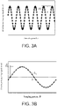
- FIG. 3A illustrates sampling of a digitized distance-measuring signal M by the electro-optical distance meter 100.
- a sampling timing of the A/D converter 30 is determined so that one period of the distance-measuring signal M is always sampled at constant phase angle positions, for example, one period is divided equally into a (a ⁇ 3).
- the distance-measuring signal M is successively sampled over multiple periods of thousands of periods or more.
- sampling data of the distance-measuring signal M exceeding an input range of the A/D converter 30 or much smaller than the input range is discarded.
- a storage area of the storage unit 50 corresponding to N data of one period of the distance-measuring signal M is prepared, and N sampling data at the same phase position are synchronously added and stored.
- synthetic data S of the distance-measuring signal M of one period with a large amplitude obtained by synchronously adding sampling data at the same phase positions is created.
- This synthetic data S is applied to a synthetic sine wave S 1 by the method of least squares, and an initial phase ⁇ of this synthetic sine wave S 1 is obtained.
- This synthetic sine wave S 1 can also be expressed by the following expression: Nasin ⁇ ⁇ ⁇ + Nb (Here, N is the number of distance-measuring signals M added, a is an average amplitude of the distance-measuring signal M, b is a bias level, ⁇ is coordinates regulating an angle corresponding to a sampling position, and ⁇ is an initial phase.)
- the distance-measuring light L is used as reference light R and caused to pass through the received light amount adjusting means 21A having the same configuration as that of the received light amount adjusting means 21 through the inside of the electro-optical distance meter 100, and guided to the light receiving element 22.
- a measurement value is corrected by a publicly known method based on a result of measurement using the reference light R.
- an actually measured distance-measuring signal includes noise.
- Noise occurring during a distance measurement includes a reference signal, an electrical noise signal EL generated from various electronic circuits, and an optical noise signal IR generated when a distance-measuring light L emitted from the light source 11 is reflected by the inside of the instrument such as an objective lens and unintentionally enters the light receiving element 22.
- FIG. 4 is a diagram illustrating a relationship among a true distance-measuring signal M T , an actually measured distance-measuring signal M, an optical noise signal IR, and an electrical noise signal EL.
- the true distance-measuring signal M T can be obtained by subtracting the optical noise signal IR and the electrical noise signal EL from the actually measured distance-measuring signal M.
- M T ⁇ M ⁇ ⁇ IR ⁇ + EL ⁇ So, a method for measuring these optical noise signal IR and electrical noise signal EL will be described.
- An electrical noise signal EL can be measured by activating the electro-optical distance meter 100 under, for example, the following condition I.
- FIG. 5A schematically illustrates a method for measuring electrical noise.
- the distance-measuring light L is emitted under the condition I
- the distance-measuring light L is emitted through the light transmitting optical system and the objective lens 60.
- the received light amount adjusting means 21 are blocked by the received light amount adjusting means 21 and do not enter the light receiving element 22, and no signal of incident light is generated.
- the reference signal generated by the reference signal oscillator and other noise generated from various electronic circuits enter circuits after the light receiving element 22 and generate an electrical noise signal EL. Therefore, a measurement noise signal N I measured under the condition I is an electrical noise signal EL.
- an optical noise signal IR can be measured, for example, as follows.
- a condition (0) is met.
- the Condition (0) is that a collimation direction of the electro-optical distance meter 100 is set toward the night sky without obstacles, that is, reflected light of the distance-measuring light L does not enter the objective lens 60. Then, under the condition II, the electro-optical distance meter 100 is activated to measure the signal.
- FIG. 5B schematically illustrates a method for measuring an optical noise signal IR.
- the distance-measuring light L emitted from the light source 11 in the condition II is output toward the night sky without obstacles through the objective lens 60.
- no obstacle that reflects the distance-measuring light L is present, so that the distance-measuring light L is not reflected, and no reflected distance-measuring light enters the objective lens 60.
- a part La of the distance-measuring light L is reflected by the inside of the instrument such as the back surface of the objective lens 60 and advances through the light receiving optical system, and is transmitted through the received light amount adjusting means 21to enter the light receiving element 22. Due to the incident light La, an optical noise signal IR is generated. At this time, in the light receiving element 22, an electrical noise signal EL generated from electronic circuits, etc., is also detected.
- a measurement noise signal N II measured under the condition II has a synthetic vector of the optical noise signal IR and the electrical noise signal EL generated simultaneously. Therefore, the optical noise signal IR is obtained by vectorially subtracting, from the measurement noise signal N II measured under the condition II, the measurement noise signal N I , that is, the electrical noise signal EL, measured in the condition I under the same condition (0).
- Measurement noise signals N I and N II measured under the condition I and the condition II exhibit the same behavior as the distance-measuring signal M illustrated in FIG. 3A . Therefore, when synthetic data and synthetic sine wave of the measurement noise signals N I and N II are obtained in the same manner as in the case where synthetic data S and synthetic sine wave S 1 of the distance-measuring signal M illustrated in FIG.
- a synthetic sine wave of the noise signals is expressed by the general expression of Expression 4: Na ⁇ sin ⁇ ⁇ ⁇ + Nb (Here, N is the number of noise waves added, a is an average amplitude of noise, b is a bias level, ⁇ is an initial phase, and ⁇ is coordinates regulating an angle corresponding to a sampling position.)
- one wave of the measurement noise signal N I measured by activating the electro-optical distance meter 100 under the condition I is expressed by the following Expression 5: a I ⁇ sin ⁇ ⁇ ⁇ I + b I (Here, a I is an average amplitude of the measurement noise signal N I , ⁇ I is an initial phase of the measurement noise signal, and b I is a bias level.)
- One wave of a measurement noise signal N II measured by activating the electro-optical distance meter 100 under the condition II can be expressed by the following expression 6: a II . sin ⁇ ⁇ ⁇ II + b II (Here, a II is an average amplitude of the measurement noise signal N II , ⁇ II is an initial phase of the measurement noise signal, and b II is a bias level.)
- the measurement noise signal N II measured under the condition II is a synthetic noise signal of an electrical noise signal EL and an optical noise signal IR, and is expressed vectorially as illustrated in FIG. 6 .
- an average amplitude a IR and an initial phase ⁇ IR of an optical noise signal IR can be respectively expressed by the following Expression 7 and Expression 8.
- a II is an average amplitude of the measurement noise signal N II and ⁇ II is an initial phase of the measurement noise signal N II
- a I is an average amplitude of the measurement noise signal N I and ⁇ I is an initial phase of the measurement noise signal N I .
- ⁇ IR tan ⁇ 1 a II sin ⁇ II ⁇ a I sin ⁇ I / a II cos ⁇ II ⁇ a I cos ⁇ I ⁇
- a II is an average amplitude of the measurement noise signal N II and ⁇ II is an initial phase of the measurement noise signal N II
- a I is an average amplitude of the measurement noise signal N I and ⁇ I is an initial phase of the measurement noise signal N I .
- the distance-measuring signal M obtained at the time of a distance measurement is expressed by Expression 1.
- this Expression 1 includes noise signals (optical noise signal IR and electrical noise signal EL). Accordingly, an initial phase ⁇ T of a true distance-measuring signal M T from which the noises have been removed from Expression 1 can be obtained from the following Expression 9.
- ⁇ T tan ⁇ 1 Asin ⁇ ⁇ a EL sin ⁇ EL ⁇ a IR sin ⁇ IR / Acos ⁇ ⁇ a EL cos ⁇ EL ⁇ a IR cos ⁇ IR ⁇
- A is an average amplitude of the distance-measuring signal M
- ⁇ is an initial phase of the distance-measuring signal M
- a EL is an average amplitude of the electrical noise signal
- ⁇ EL is an initial phase of the electrical noise signal
- a IR is an average amplitude of the optical noise signal IR
- ⁇ IR is an initial phase of the optical noise signal IR.
- the initial phase ⁇ T of the true distance-measuring signal M T in which noises have been removed can be calculated by using the average amplitude a EL and the initial phase ⁇ EL of the electrical noise signal EL, and the average amplitude a IR and the initial phase ⁇ IR of the optical noise signal IR, included in the distance-measuring signal M.
- a noise measuring jig 80 is attached to the electro-optical distance meter 100 and used to perform a measurement.
- the noise measuring jig 80 is detachably attached to a telescope 100a of the electro-optical distance meter 100 so as to close the objective lens 60, and has optical characteristics to remove reflected light by absorbing the distance-measuring light when attached.
- a telescope 100a of the electro-optical distance meter 100 so as to close the objective lens 60, and has optical characteristics to remove reflected light by absorbing the distance-measuring light when attached.
- Patent Literature 2 one disclosed in Patent Literature 2 can be used.
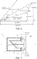
- FIG. 7 illustrates the noise measuring jig 80 similar to one disclosed in Patent Literature 2.
- the noise measuring jig 80 includes a cylindrical housing 81 opened at one side, and a donut-disc-shaped lid body 82 that has an opening at a center and closes the opening of the housing 81.
- the housing 81 is made of a non-translucent metal or resin.
- a glass filter 83 that absorbs light of a wavelength of the distance-measuring light L, and a laser light absorber 84 such as black flocked paper are provided.
- the noise measuring jig 80 is attached to the electro-optical distance meter 100 so that an axial line C of the housing 81 matches an optical axis B of the distance-measuring light L.
- the glass filter 83 is disposed so that the distance-measuring light L enters at a Brewster's angle ⁇ .
- the laser light absorber 84 is disposed so that light reflected by the glass filter 83 enters the laser light absorber 84.
- the noise measuring jig 80 is configured so that a polarization plane of the distance-measuring light L as linearly polarized light becomes a plane of incidence on the glass filter 83.
- the distance-measuring light L becomes P-wave and is refracted to enter the inside of the glass filter 83, and is absorbed by the glass filter 83.
- the distance-measuring light L is not perfect linearly polarized light, however, S-wave is reflected by the glass filter 83 and absorbed by the laser light absorber 84.
- FIG. 8A illustrates noise measured under the condition I in a state where the noise measuring jig 80 is attached.
- the distance-measuring light L enters the noise measuring jig 80 through the objective lens 60. At this time, a part of the distance-measuring light L advances as internal reflected light La toward the light receiving element 22. In addition, while most of the distance-measuring light L that has entered the noise measuring jig 80 is absorbed by the noise measuring jig 80, a part of the distance-measuring light L advances as returning light Lb toward the light receiving element 22. However, the received light amount adjusting means 21 blocks the internal reflected light La and the returning light Lb, and in the light receiving element 22, as a measurement noise signal N Ia , only an electrical noise signal EL is detected.
- FIG. 8B illustrates noise measured under the condition II in a state where the noise measuring jig 80 is attached.
- the internal reflected light La and the returning light Lb advance toward the light receiving element 22.
- the internal reflected light La and the returning light Lb are transmitted through the received light amount adjusting means 21 and detected by the light receiving element 22.
- a measurement noise signal N IIa in addition to an electrical noise signal EL and an optical noise signal IR derived from the internal reflected light La, a jig-derived noise signal IR j derived from the returning light Lb is detected.
- FIG. 9 is a view vectorially illustrating relationships of the measurement noise signal N IIa with the optical noise signal IR, the jig-derived noise signal IR j , and the electrical noise signal EL, measured with the noise measuring jig attached under the condition IIa.
- the measurement noise signal N IIa is a synthetic vector of the electrical noise signal EL, the optical noise signal IR, and the jig-derived noise signal IR j .
- the optical noise signal IR can be obtained.
- the electrical noise signal EL can be measured as a measurement noise signal N Ia by measurement under the condition Ia.
- the jig-derived noise signal IR j cannot be directly measured.
- the electrical noise signal EL greatly fluctuates due to environmental changes such as changes in surrounding temperature and power supply (battery) voltage, and mechanical deterioration caused by aging.
- the optical noise signal IR and the jig-derived noise signal IR j are values that do not fluctuate due to measurement conditions, environmental changes and changes caused by aging and are unique to the instrument (electro-optical distance meter 100) or the jig.
- the optical noise signal IR is known in advance by subtracting the measurement noise signal N I (that is, the electrical noise signal EL) measured under the condition I in a state where collimation to a night sky is performed from the measurement noise signal N II measured under the condition I in a state where collimation to a night sky is performed.
- the jig-derived noise signal IR j is a value unique to the jig.
- the jig-derived noise signal IR j is the same value even when a measurement is performed with another electro-optical distance meter as long as the conditions of the distance-measuring light L such as a laser light wavelength and energy, and a light receiving signal reading method, are the same, that is, as long as the electro-optical distance meter has the same configuration as that of the electro-optical distance meter 100.
- the average amplitude a IR and the initial phase ⁇ IR of the optical noise signal IR can be expressed as functions of the average amplitudes a Ia , a IIa , and a IRj and initial phases ⁇ Ia , ⁇ IIa , and ⁇ IRj .
- FIG. 10 is a flowchart at the time of adjustment before factory shipment or at an agency.
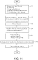
- FIG. 11 is a flowchart when a measurement is performed.
- a noise measuring jig 80 whose jig-derived noise signal IR j is known is used.
- values of an average amplitude a j and an initial phase ⁇ j of the jig-derived noise signal IR j are indicated.
- Step S01 the average amplitude a j and initial phase ⁇ j of the jig-derived noise signal IR j are input into the arithmetic control unit 40.
- the arithmetic control unit 40 displays an input screen for the average amplitude a j and initial phase ⁇ j of the jig-derived noise signal IR j on the display unit, and from the input unit, a worker inputs the average amplitude a j and initial phase ⁇ j of the jig-derived noise signal IR j visually read from the noise measuring jig 80.
- a program for performing a jig-derived noise measurement is called from a general-purpose computer connected by an external interface, and the values can be input from the computer terminal.
- This general-purpose computer terminal is configured by, for example, a CPU, a RAM, a ROM, a hard disk, an external storage device, and a network interface, etc.
- Step S02 under the condition Ia, the arithmetic control unit 40 activates the electro-optical distance meter 100 and measures a measurement noise signal N Ia as a first measurement noise signal.
- Step S03 the arithmetic control unit 40 calculates an average amplitude a Ia and an initial phase ⁇ Ia of the measurement noise signal N Ia , and stores these in the storage unit 50.
- Step S04 under the condition IIa, the arithmetic control unit 40 activates the electro-optical distance meter 100 and measures a measurement noise signal N IIa as a second measurement noise signal.
- Step S05 the arithmetic control unit 40 calculates an average amplitude a IIa and an initial phase ⁇ IIa of the measurement noise signal N IIa , and stores these in the storage unit 50.
- Step S06 by using the average amplitudes a Ia , a IIa , and a IRj and initial phases ⁇ Ia , ⁇ IIa , and ⁇ IRj , the arithmetic control unit 40 calculates an average amplitude a IR and an initial phase ⁇ IR of the optical noise signal IR by subtracting the measurement noise signal N Ia and the jig-derived noise signal IR j from the measurement noise signal N IIa , and stores these as an optical noise signal IR in the storage unit 50.
- the average amplitude a Ia and the initial phase ⁇ Ia in Step S02 and the average amplitude a IIa and the initial phase ⁇ IIa in Step S04 may be discarded or held after being used for calculation of the average amplitude a IR and the initial phase ⁇ IR in Step S05.
- measurement is performed by collimation to a measuring object (for example, a target).
- Step S11 under the condition I, the arithmetic control unit 40 activates the electro-optical distance meter 100 and measures a measurement noise signal N I .
- Step S12 the arithmetic control unit 40 calculates, an average amplitude a I and an initial phase ⁇ I of the measurement noise signal N I , and stores these as an average amplitude a EL and an initial phase ⁇ EL of the electrical noise signal EL in the storage unit 50.
- Step S13 the arithmetic control unit 40 activates the electro-optical distance meter 100 and adjusts the received light amount adjusting means 21 so that the received light amount becomes proper (proper condition), emits distance-measuring light to measure a distance-measuring signal M based on reflected distance-measuring light L by setting a multiplication factor of the light receiving element to an optimum value.
- Step S14 the arithmetic control unit 40 obtains an average amplitude A and an initial phase ⁇ of the measured distance-measuring signal M.
- Step S15 the arithmetic control unit 40 reads the average amplitude a IR and the initial phase ⁇ IR of the optical noise signal IR from the storage unit 50.
- Step S16 based on the average amplitudes a IR , a EL , and A and initial phases ⁇ IR , ⁇ EL , and ⁇ , an initial phase ⁇ T of a true distance-measuring signal M T in which noise has been removed by subtracting the optical noise signal IR and the electrical noise signal EL from the distance-measuring signal M is calculated.
- Step S17 the arithmetic control unit 40 calculates a distance D T in which an error caused by noise has been removed based on the calculated initial phase ⁇ T , and ends the processing.
- FIG. 12 is a flowchart of measuring a jig-derived noise signal IR j .
- an electro-optical distance meter 100 ⁇ having the same mechanical configuration as that of the electro-optical distance meter 100 is used.
- the components of the electro-optical distance meter 100 ⁇ are represented by adding x to the same reference signs as in the electro-optical distance meter 100. The same applies to noise caused by the electro-optical distance meter 100 ⁇ .
- Step S21 in a state where collimation to a night sky is performed, under the condition I, the arithmetic control unit 40x activates the electro-optical distance meter 100 ⁇ and measures a noise signal N Ix as a third noise signal.
- Step S22 the arithmetic control unit 40x calculates an average amplitude a Ix and an initial phase ⁇ Ix of the noise signal N Ix , and stores these in the storage unit 50x.
- Step S23 in a state where collimation to a night sky is performed, under the condition II, the arithmetic control unit 40x activates the electro-optical distance meter 100 ⁇ , and measures a noise signal N IIx as a fourth noise signal.
- Step S24 the arithmetic control unit 40x calculates an average amplitude a IIx and an initial phase ⁇ IIx of the noise signal N IIx , and stores these in the storage unit 50x.
- Step S25 by using the average amplitudes a Ix and a IIx and the initial phases ⁇ Ix and ⁇ IIx , the arithmetic control unit 40x calculates an average amplitude a IRx and an initial phase ⁇ IRx of the optical noise signal IR x obtained by subtracting the noise signal N Ix from the noise signal N IIX , and stores these as an optical noise signal IR x in the storage unit 50x.
- Step S26 under the condition Ia, the arithmetic control unit 40x activates the electro-optical distance meter 100 ⁇ , and measures a noise signal N Iax as a fifth measurement noise signal.
- Step S27 the arithmetic control unit 40x calculates an average amplitude a Iax and an initial phase ⁇ Iax of the measurement noise signal N Iax , and stores these in the storage unit 50x.
- Step S28 under the condition IIa, the arithmetic control unit 40x activates the electro-optical distance meter 100 ⁇ and measures a measurement noise signal N IIax as a sixth measurement noise signal.
- Step S29 the arithmetic control unit 40x calculates an average amplitude a IIax and an initial phase ⁇ IIax of the noise signal N IIax , and stores these in the storage unit 50x.
- Step S30 by using the average amplitudes a Iax , a IIax , and a IRx and initial phases ⁇ Iax , ⁇ IIax , and ⁇ IRx , the arithmetic control unit 40 calculates an average amplitude a IRj and an initial phase ⁇ IRj of a jig-derived noise signal IR j obtained by subtracting the measurement noise signal N Iax and the optical noise signal IR x from the measurement noise signal N IIax , and stores these in the storage unit 50x.
- Step S31 the arithmetic control unit 40x outputs the calculated average amplitude a IRj and initial phase ⁇ IRj of the jig-derived noise signal N IRj .
- the values may be displayed on the display unit.
- the values may be output to a data collector, an external terminal, a USB memory, or the like through an external interface.
- the optical noise signal IRx of the electro-optical distance meter 100 ⁇ can be known through the steps as illustrated in FIG. 13 and stored in the storage unit 50x.
- the electro-optical distance meter 100 configured to execute the operation described above is configured so as to calculate a distance value from a true distance-measuring signal M T obtained by subtracting an optical noise signal IR stored in advance in the storage unit and an electrical noise signal EL measured before a distance measurement from a distance-measuring signal M, so that an error in a distance value caused by noise can be reduced without specially devising components and wirings.
- an accurate optical noise signal IR can be obtained by using the noise measuring jig 80.
- the accuracy in distance calculation is improved.
- the optical noise signal IR is normally small, and takes time to measure.
- it is not necessary to measure an optical noise signal IR at the time of a distance measurement so that the time to be taken from the distance measurement to calculation can be shortened.
- the electrical noise signal EL can be removed, and in this regard, more accurate distance calculation can be performed.
- a measurement of an optical noise signal IR is enabled by attaching the noise measuring jig 80, so that each measurement of an optical noise signal IR does not need to be performed outdoors at night, and the work load can be reduced.
- the noise measuring jig 80 can be used any number of times to measure optical noise signals IR of other electro-optical distance meters 100.
- the noise measuring jig 80 the noise measuring jig 80 disclosed in Patent Literature 2 is used.
- the noise measuring jig 80 is configured to absorb light entering the jig so that the light hardly returns to the electro-optical distance meter 100.
- the noise measuring jig 80 is not limited to this, and only has to have a unique j ig-derived noise signal IR j .
- a deflecting mirror is disposed at 45° with respect to an optical axis of distance-measuring light, and a laser absorber is disposed at a position where reflected light enters.
- an absolute value of the jig-derived noise signal IR j becomes small.
- the jig-derived noise signal IR j is a unique value and rarely fluctuates. But, in actuality, the jig-derived noise signal IR j may slightly fluctuate due to the temperature and changes caused by aging. However, as the absolute value of the j ig-derived noise signal becomes small, a fluctuation value is also small, so that more accurate optical noise measurement is possible.
- the jig-derived noise signal IR j is small.
- the jig-derived noise signal is approximately 0.1 to 1.
- an optical noise signal IR derived from internal reflection can be accurately calculated, so that a minimum signal can also be used, and measurement accuracy is improved.
- a jig-derived noise signal IR j is a smaller value than an optical noise signal IR, so that it takes a longer time to measure.
- a jig-derived noise signal IR j is known in advance, and an optical noise signal IR is calculated, and accordingly, the amount of time-consuming work can be reduced, and the work efficiency can be improved.
Landscapes
- Engineering & Computer Science (AREA)
- Physics & Mathematics (AREA)
- Computer Networks & Wireless Communication (AREA)
- General Physics & Mathematics (AREA)
- Radar, Positioning & Navigation (AREA)
- Remote Sensing (AREA)
- Electromagnetism (AREA)
- Optical Radar Systems And Details Thereof (AREA)
- Measurement Of Optical Distance (AREA)
Abstract
Description
- The present invention relates to an electro-optical distance meter, and more specifically, to an electro-optical distance meter that measures a distance to a target by emitting distance-measuring light to the target and receiving the distance-measuring light reflected by the target, and a method for calculating an optical noise signal of the electro-optical distance meter.
- An electro-optical distance meter that measures a distance to a target by emitting distance-measuring light to the target and receiving the distance-measuring light reflected by the target, as disclosed in
Patent Literature 1 has been known. - In the electro-optical distance meter, in some cases, a reference signal and noise generated from various electronic circuits enter a circuit of a light receiving unit side due to electrostatic coupling, electromagnetic coupling, and electromagnetic radiation, etc., without reciprocating to a target, and cause electrical noise, and as a result, an error occurs in a distance value. In the electro-optical distance meter of
Patent Literature 1, before a distance measurement, (1) in a state where a diaphragm just before a light receiving element is narrowed most, (2) a light source is caused to emit light, and (3) a multiplication factor of the light receiving element is controlled to a proper value, noise is measured, and an amplitude and an initial phase of the noise are obtained and stored in a storage unit, and at the time of the distance measurement, based on these amplitude and initial phase, a distance from which an error caused by the noise has been removed is calculated (refer to Paragraph [0045]). This can reduce errors without devising components and wirings. -
-
Patent Literature 1JP2009-258006A -
Patent Literature 2JP2010-032421A - However, noise that causes an error in a distance value in an electro-optical distance meter includes not only electrical noise but also optical noise caused by the distance-measuring light being reflected by the inside of the electro-optical distance meter to enter into the light receiving element. In the electro-optical distance meter disclosed in
Patent Literature 1, optical noise reduction is not considered. - The present invention has been made in view of these circumstances, and an object thereof is to provide an electro-optical distance meter in which an error in a distance value caused by noise is further reduced without specially devising components and wirings.
- In order to achieve the object described above, an electro-optical distance meter according to an aspect of the present invention includes a first light source configured to emit distance-measuring light toward a measuring object, a first light receiving unit including a first light receiving element configured to receive the distance-measuring light reflected by the measuring object and convert the distance-measuring light into a distance-measuring signal, and a first received light amount adjusting means configured to adjust a light amount entering the first light receiving element, a first objective lens configured to condense the reflected distance-measuring light to the first light receiving unit, a first arithmetic control unit configured to calculate a distance to the measuring object from an initial phase of the distance-measuring signal, and a first storage unit configured to store the distance-measuring signal, distance value data, and an optical noise signal, and configured to measure an electrical noise signal by putting the first received light amount adjusting means into a state where the first received light amount adjusting means completely blocks light and causing the first light source to emit light, measure a distance-measuring signal of the measuring object by putting the first received light amount adjusting means into a proper state, and calculate a distance by subtracting the electrical noise signal and the optical noise signal from the distance-measuring signal, wherein the first arithmetic control unit measures a first noise signal by putting the first received light amount adjusting means into a state where the first received light amount adjusting means completely blocks light and causing the first light source to emit light with a noise measuring jig having a unique jig-derived noise signal attached, the noise measuring jig being attachable to and detachable from the electro-optical distance meter and configured to remove reflected distance-measuring light entering the first light receiving unit when attached, measures a second noise signal by putting the first received light amount adjusting means into a state where the first received light amount adjusting means transmits light most and causing the first light source to emit light in a state where the noise measuring jig is attached, and calculates the optical noise signal by subtracting the first noise signal and the jig-derived noise stores the optical noise signal from the second noise signal, and in the storage unit.
- In the aspect described above, it is also preferable that, the jig-derived noise signal is obtained by, by using a second electro-optical distance meter including a second light source configured to emit distance-measuring light toward a measuring object, a second light receiving unit including a second light receiving element configured to receive the distance-measuring light reflected by the measuring object and convert the distance-measuring light into a distance-measuring signal, and a second received light amount adjusting means configured to adjust a light amount entering the second light receiving element, a second objective lens configured to condense the reflected distance-measuring light to the second light receiving unit, a second arithmetic control unit configured to calculate a distance to the measuring object based on the distance-measuring signal, and a second storage unit, in a state where collimation to a night sky is performed, measuring a third noise signal by putting the second received light amount adjusting means into a state where the second received light amount adjusting means completely blocks light and causing the second light source to emit light, measuring a fourth noise signal by putting the second received light amount adjusting means into a state where the second received light amount adjusting means transmits light most and causing the second light source to emit light, and calculating an optical noise signal unique to the second electro-optical distance meter by subtracting the third noise signal from the fourth noise signal, measuring a fifth measurement noise signal by putting the second received light amount adjusting means into a state where the second received light amount adjusting means completely blocks light and causing the second light source to emit light in a state where the noise measuring jig is attached, measuring a sixth measurement noise signal by putting the second received light amount adjusting means into a state where the second received light amount adjusting means transmits light most in a state where the noise measuring jig is attached, and subtracting the fifth measurement noise signal and the unique optical noise signal from the sixth measurement noise signal.
- In the aspect described above, it is also preferable that the noise measuring jig includes a bottomed cylindrical housing, a glass filter configured to absorb light of a wavelength of the distance-measuring light, and a laser light absorber configured to absorb the distance-measuring light reflected by the glass filter, and the glass filter is installed so that distance-measuring light emitted through the first or second objective lens in an attached state of the noise measuring jig enters the glass filter at a Brewster's angle.
- A method for calculating an optical noise according to another aspect of the present invention, uses an electro-optical distance meter including a light source configured to emit distance-measuring light toward a measuring object, a light receiving unit including a light receiving element configured to receive the distance-measuring light reflected by the measuring object and convert the distance-measuring light into a distance-measuring signal, and a received light amount adjusting means configured to adjust a light amount entering the light receiving element, a storage unit configured to store an optical noise signal, and an arithmetic control unit configured to calculate a distance to the measuring object based on the distance-measuring signal, and a noise measuring jig having a unique jig-derived noise signal, attachable to and detachable from the electro-optical distance meter, and configured to remove reflected distance-measuring light entering the light receiving unit when attached, and includes measuring a first noise signal by putting the received light amount adjusting means into a state where the received light amount adjusting means completely blocks light and causing the light source to emit light with the noise measuring jig attached, measuring a second noise signal by putting the received light amount adjusting means into a state where the received light amount adjusting means transmits light most and causing the light source to emit light with the noise measuring jig attached, calculating the optical noise signal by subtracting the first noise signal and the jig-derived noise signal from the second noise signal, measuring an electrical noise signal by putting the received light amount adjusting means into a state where the received light amount adjusting means completely blocks light and causing the light source to emit light, and calculating the distance by subtracting the electrical noise signal and the optical noise signal from the distance-measuring signal of the measuring object measured by putting the received light amount adjusting means into a proper state.
- Herein, " true distance-measuring signal " refers to the signal component obtained by removing noise signals from measured distance-measuring signal.
- According to the aspects described above, an electro-optical distance meter in which an error in a distance value caused by noise is further reduced without specially devising components and wirings can be provided.
-
-
FIG. 1 is a block diagram of an electro-optical distance meter according to an embodiment of the present invention. -
FIG. 2 is a view illustrating an example of a received light amount adjusting means of the electro-optical distance meter. -
FIG. 3A is a diagram illustrating sampling data of a distance-measuring signal of the electro-optical distance meter, andFIG. 3B is a diagram illustrating synchronous addition data of the distance-measuring signal. -
FIG. 4 is a diagram illustrating a relationship among distance signal vectors and noise signal vectors in the electro-optical distance meter. -
FIGS. 5A and 5B are views describing examples of noise measurement methods in the electro-optical distance meter,FIG. 5A describes a method for measuring an electrical noise signal, andFIG. 5B describes a method for measuring an optical noise signal. -
FIG. 6 is a diagram describing a method for calculating an average amplitude and an initial phase of an optical noise signal, and an initial phase of a true distance-measuring signal in the electro-optical distance meter. -
FIG. 7 is a longitudinal sectional view of an example of a noise measuring jig to be used by being attached to the electro-optical distance meter. -
FIGS. 8A and 8B are views describing noise measuring methods using the noise measuring jig in the electro-optical distance meter. -
FIG. 9 is a view illustrating relationships of a noise signal measured by using the noise measuring jig with an optical noise signal and an electrical noise signal. -
FIG. 10 is a flowchart when measuring an optical noise signal in the electro-optical distance meter. -
FIG. 11 is a flowchart of processing when measuring a distance in the electro-optical distance meter. -
FIG. 12 is a flowchart of steps for measuring a jig-derived noise of a noise measuring jig by using another electro-optical distance meter. - Hereinafter, preferred embodiments of the present invention will be described with reference to the drawings, however, the present invention is not limited to these. In each embodiment, the same components are provided with the same reference sign, and overlapping description will be omitted.
- An electro-
optical distance meter 100 according to the present embodiment is a so-called phase difference system electro-optical distance meter. As illustrated inFIG. 1 , generally, the electro-optical distance meter includes alight transmitting unit 10, alight receiving unit 20, an A/D (Analog/Digital)converter 30, anarithmetic control unit 40, astorage unit 50, and anobjective lens 60, and these are housed in a housing configured like a telescope. - The
light transmitting unit 10 includes alight source 11, a light transmitting optical system (not illustrated), amodulator 12, and areference signal oscillator 13. Thelight source 11 is, for example, a light emitting element such as a laser diode, and emits distance-measuring light L along a collimation axis toward atarget 70 such as a prism placed on a survey point through the light transmitting optical system and an objective lens. Thelight source 11 is connected to themodulator 12, and themodulator 12 is connected to thereference signal oscillator 13. Thereference signal oscillator 13 generates a reference signal K with a constant frequency. Themodulator 12 modulates the reference signal K to a modulated signal K1. - The
light receiving unit 20 includes a light receiving optical system (not illustrated), received light amount adjusting means 21, 21A, alight receiving element 22, ahigh frequency amplifier 23, abandpass filter 24, afrequency converter 25, and a low-pass filter 26. - The received light amount adjusting means 21 is arranged just before the
light receiving element 22 and adjusts an amount of light entering the light receiving element. The received light amount adjusting means 21 is, for example, a variable density filter composed of a thin discoid film as illustrated inFIG. 2 . - The received light amount adjusting means 21 in
FIG. 2 has acentral hole 21a at a central portion, and has an opening 21b around thecentral hole 21a, and is formed so that a filter density continuously increases from 0% to 100% in terms of light intensity decay rate in the circumferential direction represented by arrow X inFIG. 2 from the opening 21b toward the otherend portion region 21c in the circumferential direction. The received light amount adjusting means 21 is rotated by a rotary shaft (not illustrated) of a motor inserted through thecentral hole 21a. - The received light amount adjusting means 21 is configured so that the light intensity decay rate is 0% (a state where light is transmitted most) when the opening 21b is at a position matching the
light receiving element 22, and the light intensity decay rate reaches 100% (a state where light is blocked most) when the otherend portion region 21c reaches a position matching thelight receiving element 22. Opening and closing of the received light amount adjusting means 21 (filter) are controlled by controlling motor rotation by thearithmetic control unit 40. - The received light amount adjusting means 21 is not limited to the above-described variable density filter, and a publicly known diaphragm to be used for an electro-optical distance meter can be used.
- The
light receiving element 22 is, for example, an avalanche photodiode (APD), etc. A bias voltage to be applied to thelight receiving element 22 can be controlled by a reverse voltage control unit not illustrated. The reverse voltage control unit changes the bias voltage according to a command from thearithmetic control unit 40 to control thelight receiving element 22 to a proper multiplication factor according to a surrounding brightness. Thelight receiving element 22 receives distance-measuring light L reflected by thetarget 70 through the light receiving optical system and the received light amount adjusting means 21, and converts the received distance-measuring light into a distance-measuring signal as an electric signal. - This electric signal is amplified by the high-
frequency amplifier 23, and then, noise is removed from the signal by thebandpass filter 24. - The
frequency converter 25 includes a mixer and a local oscillator. By inputting a local oscillation signal generated by the local oscillator and the distance-measuring signal from which noise has been removed into the mixer and multiplying these, the frequency converter generates a frequency component as a difference in frequency between the signals and a frequency component as a sum of the frequencies of the signals. Here, only the distance-measuring signal converted into an intermediate frequency IF as a difference in frequency between the signals is sorted out by the low-pass filter 26. - The distance-measuring signal converted into the intermediate frequency IF is amplified by an
intermediate frequency amplifier 27. The amplified distance-measuring signal is converted into a digital signal by the A/D converter 30, and stored in thestorage unit 50 through thearithmetic control unit 40. In the following description, a distance-measuring signal that has been converted into an intermediate frequency IF and converted into a digital signal is referred to as a distance-measuring signal M. - The
arithmetic control unit 40 is a processing device that realizes processing to calculate a distance based on a distance-measuring signal M obtained by performing a distance measurement by controlling thelight transmitting unit 10 and thelight receiving unit 20. As thearithmetic control unit 40, for example, at least one processor, such as a CPU (Central Processing Unit), etc., can be applied. The function of thearithmetic control unit 40 described hereinafter can be realized by a program or a circuit, or a combination of these. When the function is realized by a program, the function is realized by reading out the program stored in thestorage unit 50 into a main memory and executing the program. - In addition, the
arithmetic control unit 40 obtains a true distance-measuring signal MT by removing an optical noise signal IR and an electrical noise signal EL described later from the measured distance-measuring signal M, and calculates a distance value based on an initial phase βT of the true distance-measuring signal MT. - The
storage unit 50 is composed of a recording medium that stores, saves, and transmits information in a computer-processable format, and includes a so-called main memory and auxiliary storage device. Thestorage unit 50 stores sampling data and calculated distance value data. In addition, thestorage unit 50 stores an average amplitude aIR and an initial phase ηIR of the optical noise signal IR. Also, thestorage unit 50 stores programs for realizing functions of thearithmetic control unit 40 and the electro-optical distance meter 100. As thestorage unit 50, for example, a nonvolatile memory such as a flash memory or a ROM (Read Only Memory), a volatile memory such as a RAM (Random Access Memory), etc., can be applied. - Although not illustrated in the drawings, the electro-
optical distance meter 100 includes, as user interfaces, an input unit such as button keys and a display unit such as a liquid crystal display. In addition, although not illustrated in the drawings, the electro-optical distance meter 100 includes an external interface, for example, a communication unit, a USB port, etc., that enables external input and output of data stored in thestorage unit 50 and data to be arithmetically processed in thearithmetic control unit 40. - First, measurement of a theoretical distance by the electro-
optical distance meter 100 will be described. When the electro-optical distance meter 100 performs a distance measurement, thereference signal oscillator 13 transmits a synchronization signal P to thearithmetic control unit 40 and the A/D converter 30, and transmits a reference signal K to the modulator. The A/D converter performs sampling synchronized with the reference signal K. During the distance measurement, a light amount to be transmitted through the received light amount adjusting means 21 is fixed. -
FIG. 3A illustrates sampling of a digitized distance-measuring signal M by the electro-optical distance meter 100. A sampling timing of the A/D converter 30 is determined so that one period of the distance-measuring signal M is always sampled at constant phase angle positions, for example, one period is divided equally into a (a ≥ 3). At these sampling timings, the distance-measuring signal M is successively sampled over multiple periods of thousands of periods or more. At this time, sampling data of the distance-measuring signal M exceeding an input range of the A/D converter 30 or much smaller than the input range is discarded. - In order to store the sampling data in the
storage unit 50, a storage area of thestorage unit 50 corresponding to N data of one period of the distance-measuring signal M is prepared, and N sampling data at the same phase position are synchronously added and stored. In this way, as illustrated inFIG. 3B , synthetic data S of the distance-measuring signal M of one period with a large amplitude obtained by synchronously adding sampling data at the same phase positions is created. This synthetic data S is applied to a synthetic sine wave S1 by the method of least squares, and an initial phase β of this synthetic sine wave S1 is obtained. This synthetic sine wave S1 can also be expressed by the following expression:
- The initial phase β is equal to a phase difference between a signal obtained by dividing the frequency of the reference signal K to the same frequency as that of the intermediate frequency signal and the distance-measuring signal M. Based on this initial phase β, a distance D to the
target 70 is calculated according toExpression 2.
- It is also possible that, from the
light source 11, the distance-measuring light L is used as reference light R and caused to pass through the received light amount adjusting means 21A having the same configuration as that of the received light amount adjusting means 21 through the inside of the electro-optical distance meter 100, and guided to thelight receiving element 22. At the time of a distance measurement, a measurement value is corrected by a publicly known method based on a result of measurement using the reference light R. - However, an actually measured distance-measuring signal includes noise. Noise occurring during a distance measurement includes a reference signal, an electrical noise signal EL generated from various electronic circuits, and an optical noise signal IR generated when a distance-measuring light L emitted from the
light source 11 is reflected by the inside of the instrument such as an objective lens and unintentionally enters thelight receiving element 22. -
FIG. 4 is a diagram illustrating a relationship among a true distance-measuring signal MT, an actually measured distance-measuring signal M, an optical noise signal IR, and an electrical noise signal EL. As shown inExpression 3, the true distance-measuring signal MT can be obtained by subtracting the optical noise signal IR and the electrical noise signal EL from the actually measured distance-measuring signal M.
[Numerical Formula 1]
- An electrical noise signal EL can be measured by activating the electro-
optical distance meter 100 under, for example, the following condition I. -
- (1) The received light amount adjusting means 21 is put into a state where it completely blocks light (transmittance: 0%),
- (2) the
light source 11 is caused to emit light, and - (3) the bias voltage to be applied to the light receiving element is controlled to an optimum value (that is, a multiplication factor is set to an optimum value).
-
FIG. 5A schematically illustrates a method for measuring electrical noise. When the distance-measuring light L is emitted under the condition I, the distance-measuring light L is emitted through the light transmitting optical system and theobjective lens 60. At this time, even when there is reflected distance-measuring light that enters through theobjective lens 60 or light La reflected by the inside of the instrument such as the back surface of theobjective lens 60, these are blocked by the received light amount adjusting means 21 and do not enter thelight receiving element 22, and no signal of incident light is generated. However, the reference signal generated by the reference signal oscillator and other noise generated from various electronic circuits enter circuits after thelight receiving element 22 and generate an electrical noise signal EL. Therefore, a measurement noise signal NI measured under the condition I is an electrical noise signal EL. - On the other hand, an optical noise signal IR can be measured, for example, as follows. For example, a condition (0) is met. The Condition (0) is that a collimation direction of the electro-
optical distance meter 100 is set toward the night sky without obstacles, that is, reflected light of the distance-measuring light L does not enter theobjective lens 60. Then, under the condition II, the electro-optical distance meter 100 is activated to measure the signal. -
- (1a) The received light amount adjusting means 21 is put into a state where it transmits light most (transmittance: 100%),
- (2) the
light source 11 is caused to emit light, and - (3) the bias voltage to be applied to the
light receiving element 22 is set to an optimum value (that is, a multiplication factor is set to an optimum value). -
FIG. 5B schematically illustrates a method for measuring an optical noise signal IR. Under the condition (0), the distance-measuring light L emitted from thelight source 11 in the condition II is output toward the night sky without obstacles through theobjective lens 60. In the direction toward the night sky, no obstacle that reflects the distance-measuring light L is present, so that the distance-measuring light L is not reflected, and no reflected distance-measuring light enters theobjective lens 60. However, a part La of the distance-measuring light L is reflected by the inside of the instrument such as the back surface of theobjective lens 60 and advances through the light receiving optical system, and is transmitted through the received light amount adjusting means 21to enter thelight receiving element 22. Due to the incident light La, an optical noise signal IR is generated. At this time, in thelight receiving element 22, an electrical noise signal EL generated from electronic circuits, etc., is also detected. - As illustrated in
FIG. 4 , a measurement noise signal NII measured under the condition II has a synthetic vector of the optical noise signal IR and the electrical noise signal EL generated simultaneously. Therefore, the optical noise signal IR is obtained by vectorially subtracting, from the measurement noise signal NII measured under the condition II, the measurement noise signal NI, that is, the electrical noise signal EL, measured in the condition I under the same condition (0). - Hereinafter, a method for calculating a distance value according to the present embodiment will be described. Measurement noise signals NI and NII measured under the condition I and the condition II exhibit the same behavior as the distance-measuring signal M illustrated in
FIG. 3A . Therefore, when synthetic data and synthetic sine wave of the measurement noise signals NI and NII are obtained in the same manner as in the case where synthetic data S and synthetic sine wave S1 of the distance-measuring signal M illustrated inFIG. 3B are obtained, a synthetic sine wave of the noise signals is expressed by the general expression of Expression 4:
- Therefore, one wave of the measurement noise signal NI measured by activating the electro-
optical distance meter 100 under the condition I is expressed by the following Expression 5:
- One wave of a measurement noise signal NII measured by activating the electro-
optical distance meter 100 under the condition II can be expressed by the following expression 6:
- The measurement noise signal NII measured under the condition II is a synthetic noise signal of an electrical noise signal EL and an optical noise signal IR, and is expressed vectorially as illustrated in
FIG. 6 . - The noise signal NI measured under the condition I is an electrical noise signal EL. Therefore, an average amplitude aEL and an initial phase ηEL of the electrical noise signal EL are respectively obtained as aEL = aI and ηEL = ηI.
- Therefore, from
FIG. 6 , an average amplitude aIR and an initial phase ηIR of an optical noise signal IR can be respectively expressed by the following Expression 7 and Expression 8.
[Numerical Formula 2]
[Numerical Formula 3]
- The distance-measuring signal M obtained at the time of a distance measurement is expressed by
Expression 1. However, thisExpression 1 includes noise signals (optical noise signal IR and electrical noise signal EL). Accordingly, an initial phase βT of a true distance-measuring signal MT from which the noises have been removed fromExpression 1 can be obtained from the following Expression 9.
[Numerical Formula 4]
- Therefore, by
Expression 10 obtained by replacing β inExpression 2 with βT in Expression 9, a distance DT in which an error caused by noises has been removed can be obtained.
- In this way, the initial phase βT of the true distance-measuring signal MT in which noises have been removed can be calculated by using the average amplitude aEL and the initial phase ηEL of the electrical noise signal EL, and the average amplitude aIR and the initial phase ηIR of the optical noise signal IR, included in the distance-measuring signal M.
- For measurement under the condition that the reflected distance-measuring light does not enter the
light receiving unit 20, it is necessary on an instrument-to-instrument basis to install the electro-optical distance meter 100 at an outdoor location without obstacles at night. However, this work is very time-consuming. Therefore, anoise measuring jig 80 is attached to the electro-optical distance meter 100 and used to perform a measurement. - The
noise measuring jig 80 is detachably attached to atelescope 100a of the electro-optical distance meter 100 so as to close theobjective lens 60, and has optical characteristics to remove reflected light by absorbing the distance-measuring light when attached. As an example, one disclosed inPatent Literature 2 can be used. -
FIG. 7 illustrates thenoise measuring jig 80 similar to one disclosed inPatent Literature 2. Thenoise measuring jig 80 includes acylindrical housing 81 opened at one side, and a donut-disc-shapedlid body 82 that has an opening at a center and closes the opening of thehousing 81. Thehousing 81 is made of a non-translucent metal or resin. Inside thehousing 81, aglass filter 83 that absorbs light of a wavelength of the distance-measuring light L, and alaser light absorber 84 such as black flocked paper are provided. - The
noise measuring jig 80 is attached to the electro-optical distance meter 100 so that an axial line C of thehousing 81 matches an optical axis B of the distance-measuring light L. Theglass filter 83 is disposed so that the distance-measuring light L enters at a Brewster's angle α. In addition, thelaser light absorber 84 is disposed so that light reflected by theglass filter 83 enters thelaser light absorber 84. Thenoise measuring jig 80 is configured so that a polarization plane of the distance-measuring light L as linearly polarized light becomes a plane of incidence on theglass filter 83. - With the configuration described above, most of the distance-measuring light L becomes P-wave and is refracted to enter the inside of the
glass filter 83, and is absorbed by theglass filter 83. The distance-measuring light L is not perfect linearly polarized light, however, S-wave is reflected by theglass filter 83 and absorbed by thelaser light absorber 84. - In this way, it was estimated that, when the
noise measuring jig 80 was attached, the distance-measuring light L was almost completely absorbed and light returning to the electro-optical distance meter 100 was removed. However, in actuality, due to diffuse reflection, etc., on a boundary surface of theglass filter 83, a slight amount of returning light that enters the electro-optical distance meter 100 through theobjective lens 60 is generated. -
FIG. 8A illustrates noise measured under the condition I in a state where thenoise measuring jig 80 is attached. -
- (1) The received light amount adjusting means 21 is put into a state where it completely blocks light (transmittance: 0%),
- (2) the
light source 11 is caused to emit light, and - (3) a bias voltage to be applied to the light receiving element is controlled to an optimum value (that is, a multiplication factor is set to an optimum value).
- Hereinafter, this condition (with noise measuring jig + condition I) is referred to as [Condition Ia].
- When the
light source 11 is caused to emit light, the distance-measuring light L enters thenoise measuring jig 80 through theobjective lens 60. At this time, a part of the distance-measuring light L advances as internal reflected light La toward thelight receiving element 22. In addition, while most of the distance-measuring light L that has entered thenoise measuring jig 80 is absorbed by thenoise measuring jig 80, a part of the distance-measuring light L advances as returning light Lb toward thelight receiving element 22. However, the received light amount adjusting means 21 blocks the internal reflected light La and the returning light Lb, and in thelight receiving element 22, as a measurement noise signal NIa, only an electrical noise signal EL is detected. -
FIG. 8B illustrates noise measured under the condition II in a state where thenoise measuring jig 80 is attached. -
- (1a) The received light amount adjusting means 21 is put into a state where it transmits light most (transmittance: 100%),
- (2) the
light source 11 is caused to emit light, and - (3) the bias voltage to be applied to the
light receiving element 22 is set to an optimum value (that is, a multiplication factor is set to an optimum value). - Hereinafter, this condition is referred to as [Condition IIa].
- When the
light source 11 is caused to emit light, as inFIG. 8A , the internal reflected light La and the returning light Lb advance toward thelight receiving element 22. The internal reflected light La and the returning light Lb are transmitted through the received light amount adjusting means 21 and detected by thelight receiving element 22. In thelight receiving element 22, as a measurement noise signal NIIa, in addition to an electrical noise signal EL and an optical noise signal IR derived from the internal reflected light La, a jig-derived noise signal IRj derived from the returning light Lb is detected. -
FIG. 9 is a view vectorially illustrating relationships of the measurement noise signal NIIa with the optical noise signal IR, the jig-derived noise signal IRj, and the electrical noise signal EL, measured with the noise measuring jig attached under the condition IIa. As described above, the measurement noise signal NIIa is a synthetic vector of the electrical noise signal EL, the optical noise signal IR, and the jig-derived noise signal IRj. - Therefore, by subtracting the jig-derived noise signal IRj and the electrical noise signal EL from the measurement noise signal NIIa, the optical noise signal IR can be obtained.
- Here, the electrical noise signal EL can be measured as a measurement noise signal NIa by measurement under the condition Ia. On the other hand, the jig-derived noise signal IRj cannot be directly measured.
- The electrical noise signal EL greatly fluctuates due to environmental changes such as changes in surrounding temperature and power supply (battery) voltage, and mechanical deterioration caused by aging. On the other hand, the optical noise signal IR and the jig-derived noise signal IRj are values that do not fluctuate due to measurement conditions, environmental changes and changes caused by aging and are unique to the instrument (electro-optical distance meter 100) or the jig.
- Therefore, by using the electro-
optical distance meter 100, the optical noise signal IR is known in advance by subtracting the measurement noise signal NI (that is, the electrical noise signal EL) measured under the condition I in a state where collimation to a night sky is performed from the measurement noise signal NII measured under the condition I in a state where collimation to a night sky is performed. - Next, by using the optical noise signal IR obtained in advance by measuring the measurement noise signal NIIa and the measurement noise signal NIa (electrical noise signal EL) by using the same electro-
optical distance meter 100, the jig-derived noise signal IRj is obtained fromExpression 11.
[Numerical Formula 5]
- The jig-derived noise signal IRj is a value unique to the jig. The jig-derived noise signal IRj is the same value even when a measurement is performed with another electro-optical distance meter as long as the conditions of the distance-measuring light L such as a laser light wavelength and energy, and a light receiving signal reading method, are the same, that is, as long as the electro-optical distance meter has the same configuration as that of the electro-
optical distance meter 100. Therefore, once the value of the jig-derived noise signal is known, by measuring the measurement noise signal NIIa and the measurement noise signal NIa with thenoise measuring jig 80 attached to an arbitrary electro-optical distance meter 100, an optical noise signal IR unique to the electro-optical distance meter 100 used for the measurement can be obtained fromExpression 12.
[Numerical Formula 6]
- All of the noise signals described above exhibit the simular behavior as that of the distance-measuring signal M, and a synthetic sine wave obtained by applying a result of synchronous addition of N data of one period of the noise signals to a sine wave is expressed by a general expression of Expression 4. Therefore, by obtaining average amplitudes aIa, aIIa, and aIRj and initial phases ηIa, ηIIa, and ηIRj of the respective noise signals and performing vector addition and subtraction, the average amplitude aIR and the initial phase ηIR of the optical noise signal IR can be expressed as functions of the average amplitudes aIa, aIIa, and aIRj and initial phases ηIa, ηIIa, and ηIRj.
- By applying this result to Expression 9, an initial phase βT of a true distance-measuring signal MT is obtained. In addition, by using the obtained initial phase βT, a distance DT from which an error caused by noise has been removed is obtained.
- An example of operation of the electro-
optical distance meter 100 according to the present embodiment will be described with reference to the flowcharts ofFIGS. 10 to 12 .FIG. 10 is a flowchart at the time of adjustment before factory shipment or at an agency.FIG. 11 is a flowchart when a measurement is performed. - For noise measurement before factory shipment, a
noise measuring jig 80 whose jig-derived noise signal IRj is known is used. On a surface of thehousing 81 of thenoise measuring jig 80, values of an average amplitude aj and an initial phase ηj of the jig-derived noise signal IRj are indicated. - First, in Step S01, the average amplitude aj and initial phase ηj of the jig-derived noise signal IRj are input into the
arithmetic control unit 40. For example, thearithmetic control unit 40 displays an input screen for the average amplitude aj and initial phase ηj of the jig-derived noise signal IRj on the display unit, and from the input unit, a worker inputs the average amplitude aj and initial phase ηj of the jig-derived noise signal IRj visually read from thenoise measuring jig 80. Alternatively, it is also possible that a program for performing a jig-derived noise measurement is called from a general-purpose computer connected by an external interface, and the values can be input from the computer terminal. This general-purpose computer terminal is configured by, for example, a CPU, a RAM, a ROM, a hard disk, an external storage device, and a network interface, etc. - Next, in Step S02, under the condition Ia, the
arithmetic control unit 40 activates the electro-optical distance meter 100 and measures a measurement noise signal NIa as a first measurement noise signal. - Next, in Step S03, the
arithmetic control unit 40 calculates an average amplitude aIa and an initial phase ηIa of the measurement noise signal NIa, and stores these in thestorage unit 50. - Next, in Step S04, under the condition IIa, the
arithmetic control unit 40 activates the electro-optical distance meter 100 and measures a measurement noise signal NIIa as a second measurement noise signal. - Next, in Step S05, the
arithmetic control unit 40 calculates an average amplitude aIIa and an initial phase ηIIa of the measurement noise signal NIIa, and stores these in thestorage unit 50. - Next, in Step S06, by using the average amplitudes aIa, aIIa, and aIRj and initial phases ηIa, ηIIa, and ηIRj, the
arithmetic control unit 40 calculates an average amplitude aIR and an initial phase ηIR of the optical noise signal IR by subtracting the measurement noise signal NIa and the jig-derived noise signal IRj from the measurement noise signal NIIa, and stores these as an optical noise signal IR in thestorage unit 50. - The average amplitude aIa and the initial phase ηIa in Step S02 and the average amplitude aIIa and the initial phase ηIIa in Step S04 may be discarded or held after being used for calculation of the average amplitude aIR and the initial phase ηIR in Step S05.
- Next, when performing a measurement, measurement is performed by collimation to a measuring object (for example, a target).
- First, in Step S11, under the condition I, the
arithmetic control unit 40 activates the electro-optical distance meter 100 and measures a measurement noise signal NI. - Next, in Step S12, the
arithmetic control unit 40 calculates, an average amplitude aI and an initial phase ηI of the measurement noise signal NI, and stores these as an average amplitude aEL and an initial phase ηEL of the electrical noise signal EL in thestorage unit 50. - Next, in Step S13, the
arithmetic control unit 40 activates the electro-optical distance meter 100 and adjusts the received light amount adjusting means 21 so that the received light amount becomes proper (proper condition), emits distance-measuring light to measure a distance-measuring signal M based on reflected distance-measuring light L by setting a multiplication factor of the light receiving element to an optimum value. - Next, in Step S14, the
arithmetic control unit 40 obtains an average amplitude A and an initial phase β of the measured distance-measuring signal M. - Next, in Step S15, the
arithmetic control unit 40 reads the average amplitude aIR and the initial phase ηIR of the optical noise signal IR from thestorage unit 50. - Next, in Step S16, based on the average amplitudes aIR, aEL, and A and initial phases ηIR, ηEL, and β, an initial phase βT of a true distance-measuring signal MT in which noise has been removed by subtracting the optical noise signal IR and the electrical noise signal EL from the distance-measuring signal M is calculated.
- Next, in Step S17, the
arithmetic control unit 40 calculates a distance DT in which an error caused by noise has been removed based on the calculated initial phase βT, and ends the processing. -
FIG. 12 is a flowchart of measuring a jig-derived noise signal IRj. For measurement of the jig-derived noise signal IRj, an electro-optical distance meter 100× having the same mechanical configuration as that of the electro-optical distance meter 100 is used. To avoid confusion, the components of the electro-optical distance meter 100× are represented by adding x to the same reference signs as in the electro-optical distance meter 100. The same applies to noise caused by the electro-optical distance meter 100×. - First, in Step S21, in a state where collimation to a night sky is performed, under the condition I, the arithmetic control unit 40x activates the electro-
optical distance meter 100× and measures a noise signal NIx as a third noise signal. - Next, in Step S22, the arithmetic control unit 40x calculates an average amplitude aIx and an initial phase ηIx of the noise signal NIx, and stores these in the storage unit 50x.
- Next, in Step S23, in a state where collimation to a night sky is performed, under the condition II, the arithmetic control unit 40x activates the electro-
optical distance meter 100×, and measures a noise signal NIIx as a fourth noise signal. - Next, in Step S24, the arithmetic control unit 40x calculates an average amplitude aIIx and an initial phase ηIIx of the noise signal NIIx, and stores these in the storage unit 50x.
- Next, in Step S25, by using the average amplitudes aIx and aIIx and the initial phases ηIx and ηIIx, the arithmetic control unit 40x calculates an average amplitude aIRx and an initial phase ηIRx of the optical noise signal IRx obtained by subtracting the noise signal NIx from the noise signal NIIX, and stores these as an optical noise signal IRx in the storage unit 50x.
- In Step S26, under the condition Ia, the arithmetic control unit 40x activates the electro-
optical distance meter 100×, and measures a noise signal NIax as a fifth measurement noise signal. - Next, in Step S27, the arithmetic control unit 40x calculates an average amplitude aIax and an initial phase ηIax of the measurement noise signal NIax, and stores these in the storage unit 50x.
- Next, in Step S28, under the condition IIa, the arithmetic control unit 40x activates the electro-
optical distance meter 100× and measures a measurement noise signal NIIax as a sixth measurement noise signal. - Next, in Step S29, the arithmetic control unit 40x calculates an average amplitude aIIax and an initial phase ηIIax of the noise signal NIIax, and stores these in the storage unit 50x.
- Next, in Step S30, by using the average amplitudes aIax, aIIax, and aIRx and initial phases ηIax, ηIIax, and ηIRx, the
arithmetic control unit 40 calculates an average amplitude aIRj and an initial phase ηIRj of a jig-derived noise signal IRj obtained by subtracting the measurement noise signal NIax and the optical noise signal IRx from the measurement noise signal NIIax, and stores these in the storage unit 50x. - Next, in Step S31, the arithmetic control unit 40x outputs the calculated average amplitude aIRj and initial phase ηIRj of the jig-derived noise signal NIRj. As the output, for example, the values may be displayed on the display unit. Alternatively, the values may be output to a data collector, an external terminal, a USB memory, or the like through an external interface.
- The optical noise signal IRx of the electro-
optical distance meter 100× can be known through the steps as illustrated in FIG. 13 and stored in the storage unit 50x. - The electro-
optical distance meter 100 configured to execute the operation described above is configured so as to calculate a distance value from a true distance-measuring signal MT obtained by subtracting an optical noise signal IR stored in advance in the storage unit and an electrical noise signal EL measured before a distance measurement from a distance-measuring signal M, so that an error in a distance value caused by noise can be reduced without specially devising components and wirings. - According to the electro-
optical distance meter 100 described above, an accurate optical noise signal IR can be obtained by using thenoise measuring jig 80. The accuracy in distance calculation is improved. The optical noise signal IR is normally small, and takes time to measure. In the electro-optical distance meter 100, it is not necessary to measure an optical noise signal IR at the time of a distance measurement, so that the time to be taken from the distance measurement to calculation can be shortened. Further, in response to fluctuation of the electrical noise signal EL, the electrical noise signal EL can be removed, and in this regard, more accurate distance calculation can be performed. - In particular, in the electro-
optical distance meter 100, a measurement of an optical noise signal IR is enabled by attaching thenoise measuring jig 80, so that each measurement of an optical noise signal IR does not need to be performed outdoors at night, and the work load can be reduced. - In addition, after a jig-derived noise signal IRj of the
noise measuring jig 80 is known by using the electro-optical distance meter 100× whose optical noise IRx has been known, thenoise measuring jig 80 can be used any number of times to measure optical noise signals IR of other electro-optical distance meters 100. - In the present embodiment, as the
noise measuring jig 80, thenoise measuring jig 80 disclosed inPatent Literature 2 is used. Thenoise measuring jig 80 is configured to absorb light entering the jig so that the light hardly returns to the electro-optical distance meter 100. Thenoise measuring jig 80 is not limited to this, and only has to have a unique j ig-derived noise signal IRj. For example, it is also possible that, inside a similar cylindrical housing, a deflecting mirror is disposed at 45° with respect to an optical axis of distance-measuring light, and a laser absorber is disposed at a position where reflected light enters. However, with a configuration in which light hardly returns as with thenoise measuring jig 80, an absolute value of the jig-derived noise signal IRj becomes small. The jig-derived noise signal IRj is a unique value and rarely fluctuates. But, in actuality, the jig-derived noise signal IRj may slightly fluctuate due to the temperature and changes caused by aging. However, as the absolute value of the j ig-derived noise signal becomes small, a fluctuation value is also small, so that more accurate optical noise measurement is possible. - As compared with an optical noise signal IR derived from internal reflection, the jig-derived noise signal IRj is small. For example, when the optical noise signal IR is 4, the jig-derived noise signal is approximately 0.1 to 1. However, under the condition that a distance-measuring signal to be received is small as in a case of non-prism distance measurement and a case where the measuring object is distant, even such a small noise signal is not negligible. In the present embodiment, an optical noise signal IR derived from internal reflection can be accurately calculated, so that a minimum signal can also be used, and measurement accuracy is improved.
- A jig-derived noise signal IRj is a smaller value than an optical noise signal IR, so that it takes a longer time to measure. In the present embodiment, a jig-derived noise signal IRj is known in advance, and an optical noise signal IR is calculated, and accordingly, the amount of time-consuming work can be reduced, and the work efficiency can be improved.
- Preferred embodiments of the present invention have been described above, and the embodiments described above are examples of the present invention, and these can be combined based on knowledge of those skilled in the art, and such a combined embodiment is also included in the scope of the present invention.
-
- 10:
- Light transmitting unit
- 11:
- Light source
- 20:
- Light receiving unit
- 21:
- Received light amount adjusting means
- 22:
- Light receiving element
- 40:
- Arithmetic control unit
- 50:
- Storage unit
- 52:
- Electrical noise
- 53:
- Optical noise
- 60:
- Objective lens
- 70:
- Target
- 100:
- Electro-optical distance meter
Claims (4)
- An electro-optical distance meter comprising:a first light source configured to emit distance-measuring light toward a measuring object;a first light receiving unit including a first light receiving element configured to receive the distance-measuring light reflected by the measuring object and convert the distance-measuring light into a distance-measuring signal, and a first received light amount adjusting means configured to adjust a light amount entering the first light receiving element;a first objective lens configured to condense the reflected distance-measuring light to the first light receiving unit;a first arithmetic control unit configured to calculate a distance to the measuring object from an initial phase of the distance-measuring signal; anda first storage unit configured to store the distance-measuring signal, distance value data, and an optical noise signal, andconfigured to measure an electrical noise signal by putting the first received light amount adjusting means into a state where the first received light amount adjusting means completely blocks light and causing the first light source to emit light, measure a distance-measuring signal of the measuring object by putting the first received light amount adjusting means into a proper state, and calculate a distance by subtracting the electrical noise signal and the optical noise signal from the distance-measuring signal, whereinthe first arithmetic control unitmeasures a first noise signal by putting the first received light amount adjusting means into a state where the first received light amount adjusting means completely blocks light and causing the first light source to emit light with a noise measuring jig having a unique jig-derived noise signal attached, the noise measuring jig being attachable to and detachable from the electro-optical distance meter and configured to remove reflected distance-measuring light entering the first light receiving unit when attached,measures a second noise signal by putting the first received light amount adjusting means into a state where the first received light amount adjusting means transmits light most and causing the first light source to emit light in a state where the noise measuring jig is attached, andcalculates the optical noise signal by subtracting the first noise signal and the jig-derived noise signal from the second noise signal, and stores the optical noise signal in the first storage unit.
- The electro-optical distance meter according to Claim 1, wherein
the jig-derived noise signal is obtained by:by using a second electro-optical distance meter including a second light source configured to emit distance-measuring light toward a measuring object, a second light receiving unit including a second light receiving element configured to receive the distance-measuring light reflected by the measuring object and convert the distance-measuring light into a distance-measuring signal, and a second received light amount adjusting means configured to adjust a light amount entering the second light receiving element, a second objective lens configured to condense the reflected distance-measuring light to the second light receiving unit, a second arithmetic control unit configured to calculate a distance to the measuring object based on the distance-measuring signal, and a second storage unit,in a state where collimation to a night sky is performed, measuring a third noise signal by putting the second received light amount adjusting means into a state where the second received light amount adjusting means completely blocks light and causing the second light source to emit light, measuring a fourth noise signal by putting the second received light amount adjusting means into a state where the second received light amount adjusting means transmits light most and causing the second light source to emit light, and calculating an optical noise signal unique to the second electro-optical distance meter by subtracting the third noise signal from the fourth noise signal,measuring a fifth measurement noise signal by putting the second received light amount adjusting means into a state where the second received light amount adjusting means completely blocks light and causing the second light source to emit light in a state where the noise measuring jig is attached, and measuring a sixth measurement noise signal by putting the second received light amount adjusting means into a state where the second received light amount adjusting means transmits light most in a state where the noise measuring jig is attached, andsubtracting the fifth measurement noise signal and the unique optical noise signal from the sixth measurement noise signal. - The electro-optical distance meter according to Claim 1 or 2, whereinthe noise measuring jig includes a bottomed cylindrical housing, a glass filter configured to absorb light of a wavelength of the distance-measuring light, and a laser light absorber configured to absorb the distance-measuring light reflected by the glass filter, andthe glass filter is installed so that distance-measuring light emitted through the first or second objective lens enters the glass filter at a Brewster's angle in an attached state of the noise measuring jig.
- A method for calculating an optical noise signal, using an electro-optical distance meter including a light source configured to emit distance-measuring light toward a measuring object, a light receiving unit including a light receiving element configured to receive the distance-measuring light reflected by the measuring object to convert the distance-measuring light into a distance-measuring signal and a received light amount adjusting means configured to adjust a light amount entering the light receiving element, a storage unit configured to store an optical noise signal, and an arithmetic control unit configured to measure an electrical noise signal by putting the received light amount adjusting means into a state where the received light amount adjusting means completely blocks light and causing the light source to emit light to calculate a distance to the measuring object by subtracting the electrical noise signal and the optical noise signal from the distance-measuring signal of the measuring object based on the distance-measuring signal, the method comprising:measuring a first noise signal by putting the received light amount adjusting means into a state where the received light amount adjusting means completely blocks light and causes the light source to emit light with a noise measuring jig attached, the jig having a unique jig-derived noise signal, attachable to and detachable from the electro-optical distance meter;measuring a second noise signal by putting the received light amount adjusting means into a state where the received light amount adjusting means transmits light most and causing the light source to emit light with the noise measuring jig attached; andcalculating the optical noise signal by subtracting the first noise signal and the jig-derived noise signal from the second noise signal.
Applications Claiming Priority (1)
| Application Number | Priority Date | Filing Date | Title |
|---|---|---|---|
| JP2021035056A JP7609660B2 (en) | 2021-03-05 | 2021-03-05 | Optical distance meter and method for calculating optical noise signal |
Publications (2)
| Publication Number | Publication Date |
|---|---|
| EP4053589A1 true EP4053589A1 (en) | 2022-09-07 |
| EP4053589B1 EP4053589B1 (en) | 2023-06-28 |
Family
ID=81346540
Family Applications (1)
| Application Number | Title | Priority Date | Filing Date |
|---|---|---|---|
| EP22159785.9A Active EP4053589B1 (en) | 2021-03-05 | 2022-03-02 | Electro-optical distance meter and method for calculating optical noise signal |
Country Status (3)
| Country | Link |
|---|---|
| US (1) | US20220283277A1 (en) |
| EP (1) | EP4053589B1 (en) |
| JP (1) | JP7609660B2 (en) |
Citations (6)
| Publication number | Priority date | Publication date | Assignee | Title |
|---|---|---|---|---|
| JP2009258006A (en) | 2008-04-18 | 2009-11-05 | Sokkia Topcon Co Ltd | Light wave range finder |
| JP2010032421A (en) | 2008-07-30 | 2010-02-12 | Sokkia Topcon Co Ltd | Non reflective tool |
| JP2014149171A (en) * | 2013-01-31 | 2014-08-21 | Topcon Corp | Light-wave range finder |
| US20180226773A1 (en) * | 2003-10-27 | 2018-08-09 | The General Hospital Corporation | Method and apparatus for performing optical imaging using frequency-domain interferometry |
| US20190113606A1 (en) * | 2017-10-15 | 2019-04-18 | Analog Devices, Inc. | Time-of-flight depth image processing systems and methods |
| US20190120944A1 (en) * | 2017-10-19 | 2019-04-25 | Topcon Corporation | Electronic Distance Meter And Modulated Frequency Determination Method Of Feedback Signal |
Family Cites Families (4)
| Publication number | Priority date | Publication date | Assignee | Title |
|---|---|---|---|---|
| JP2001074842A (en) | 1999-09-07 | 2001-03-23 | Minolta Co Ltd | Range finder |
| US12038535B2 (en) | 2017-01-27 | 2024-07-16 | Pioneer Corporation | Detection device, method of detecting distance to object, program, and storage medium |
| JP7252783B2 (en) * | 2019-02-25 | 2023-04-05 | 株式会社トプコン | distance measuring device |
| JP2022117173A (en) | 2021-01-29 | 2022-08-10 | 株式会社トプコン | Optical rangefinder and distance calculation method |
-
2021
- 2021-03-05 JP JP2021035056A patent/JP7609660B2/en active Active
-
2022
- 2022-03-02 EP EP22159785.9A patent/EP4053589B1/en active Active
- 2022-03-03 US US17/685,526 patent/US20220283277A1/en not_active Abandoned
Patent Citations (6)
| Publication number | Priority date | Publication date | Assignee | Title |
|---|---|---|---|---|
| US20180226773A1 (en) * | 2003-10-27 | 2018-08-09 | The General Hospital Corporation | Method and apparatus for performing optical imaging using frequency-domain interferometry |
| JP2009258006A (en) | 2008-04-18 | 2009-11-05 | Sokkia Topcon Co Ltd | Light wave range finder |
| JP2010032421A (en) | 2008-07-30 | 2010-02-12 | Sokkia Topcon Co Ltd | Non reflective tool |
| JP2014149171A (en) * | 2013-01-31 | 2014-08-21 | Topcon Corp | Light-wave range finder |
| US20190113606A1 (en) * | 2017-10-15 | 2019-04-18 | Analog Devices, Inc. | Time-of-flight depth image processing systems and methods |
| US20190120944A1 (en) * | 2017-10-19 | 2019-04-25 | Topcon Corporation | Electronic Distance Meter And Modulated Frequency Determination Method Of Feedback Signal |
Also Published As
| Publication number | Publication date |
|---|---|
| JP2022135319A (en) | 2022-09-15 |
| JP7609660B2 (en) | 2025-01-07 |
| EP4053589B1 (en) | 2023-06-28 |
| US20220283277A1 (en) | 2022-09-08 |
Similar Documents
| Publication | Publication Date | Title |
|---|---|---|
| KR100484345B1 (en) | Device for calibrating distance-measuring apparatus | |
| EP0091665B1 (en) | Optical distance-measuring method and apparatus therefor | |
| US12276761B2 (en) | Phase anti-aliasing using spread-spectrum techniques in an optical distance measurement system | |
| CN112444818B (en) | A laser radar | |
| JP3911575B2 (en) | Pulse-type optical rangefinder | |
| US20230037235A1 (en) | Lidar apparatus and process | |
| RU2554279C2 (en) | Laser distance meter | |
| CN102636151A (en) | Laser range finder and range finding method thereof | |
| CN113390467B (en) | Vibration and temperature measurement device and signal processing method thereof | |
| EP4053589B1 (en) | Electro-optical distance meter and method for calculating optical noise signal | |
| EP4036603A1 (en) | Electro-optical distance meter and distance calculation method | |
| US3759616A (en) | Electro-optical distance measuring instrument | |
| JP2009258006A (en) | Light wave range finder | |
| US4183671A (en) | Interferometer for the measurement of plasma density | |
| US20240319348A1 (en) | Time-of-flight camera system | |
| JP2004264116A (en) | Lightwave rangefinder | |
| RU2670245C1 (en) | Method of reading and control oscillations of wave solid-state gyroscope | |
| RU2269795C1 (en) | Method for one-positional measurement of laser emission source coordinates and device for realization of said method | |
| CN114459457A (en) | Resonant fiber-optic gyroscope system and method based on reciprocal modulation secondary demodulation | |
| RU2282211C2 (en) | Radar pulse re-circulation radio altimeter | |
| RU2610514C2 (en) | Laser phased range finder | |
| RU2165628C1 (en) | Phase direction finder | |
| JPH05323029A (en) | Distance measuring method by light wave range finder | |
| US20240319369A1 (en) | Time-of-flight camera system | |
| CN104515997A (en) | Calibration method and range finding apparatus based on single liquid crystal light valve phase measuring |
Legal Events
| Date | Code | Title | Description |
|---|---|---|---|
| PUAI | Public reference made under article 153(3) epc to a published international application that has entered the european phase |
Free format text: ORIGINAL CODE: 0009012 |
|
| STAA | Information on the status of an ep patent application or granted ep patent |
Free format text: STATUS: THE APPLICATION HAS BEEN PUBLISHED |
|
| AK | Designated contracting states |
Kind code of ref document: A1 Designated state(s): AL AT BE BG CH CY CZ DE DK EE ES FI FR GB GR HR HU IE IS IT LI LT LU LV MC MK MT NL NO PL PT RO RS SE SI SK SM TR |
|
| STAA | Information on the status of an ep patent application or granted ep patent |
Free format text: STATUS: REQUEST FOR EXAMINATION WAS MADE |
|
| 17P | Request for examination filed |
Effective date: 20221017 |
|
| RBV | Designated contracting states (corrected) |
Designated state(s): AL AT BE BG CH CY CZ DE DK EE ES FI FR GB GR HR HU IE IS IT LI LT LU LV MC MK MT NL NO PL PT RO RS SE SI SK SM TR |
|
| GRAP | Despatch of communication of intention to grant a patent |
Free format text: ORIGINAL CODE: EPIDOSNIGR1 |
|
| STAA | Information on the status of an ep patent application or granted ep patent |
Free format text: STATUS: GRANT OF PATENT IS INTENDED |
|
| INTG | Intention to grant announced |
Effective date: 20230210 |
|
| GRAS | Grant fee paid |
Free format text: ORIGINAL CODE: EPIDOSNIGR3 |
|
| GRAA | (expected) grant |
Free format text: ORIGINAL CODE: 0009210 |
|
| STAA | Information on the status of an ep patent application or granted ep patent |
Free format text: STATUS: THE PATENT HAS BEEN GRANTED |
|
| P01 | Opt-out of the competence of the unified patent court (upc) registered |
Effective date: 20230510 |
|
| AK | Designated contracting states |
Kind code of ref document: B1 Designated state(s): AL AT BE BG CH CY CZ DE DK EE ES FI FR GB GR HR HU IE IS IT LI LT LU LV MC MK MT NL NO PL PT RO RS SE SI SK SM TR |
|
| REG | Reference to a national code |
Ref country code: CH Ref legal event code: EP |
|
| P02 | Opt-out of the competence of the unified patent court (upc) changed |
Effective date: 20230526 |
|
| REG | Reference to a national code |
Ref country code: AT Ref legal event code: REF Ref document number: 1583178 Country of ref document: AT Kind code of ref document: T Effective date: 20230715 |
|
| REG | Reference to a national code |
Ref country code: IE Ref legal event code: FG4D |
|
| REG | Reference to a national code |
Ref country code: DE Ref legal event code: R096 Ref document number: 602022000152 Country of ref document: DE |
|
| P04 | Withdrawal of opt-out of the competence of the unified patent court (upc) registered |
Effective date: 20230802 |
|
| P05 | Withdrawal of opt-out of the competence of the unified patent court (upc) changed |
Effective date: 20230803 |
|
| REG | Reference to a national code |
Ref country code: LT Ref legal event code: MG9D |
|
| PG25 | Lapsed in a contracting state [announced via postgrant information from national office to epo] |
Ref country code: SE Free format text: LAPSE BECAUSE OF FAILURE TO SUBMIT A TRANSLATION OF THE DESCRIPTION OR TO PAY THE FEE WITHIN THE PRESCRIBED TIME-LIMIT Effective date: 20230628 Ref country code: NO Free format text: LAPSE BECAUSE OF FAILURE TO SUBMIT A TRANSLATION OF THE DESCRIPTION OR TO PAY THE FEE WITHIN THE PRESCRIBED TIME-LIMIT Effective date: 20230928 |
|
| REG | Reference to a national code |
Ref country code: NL Ref legal event code: MP Effective date: 20230628 |
|
| REG | Reference to a national code |
Ref country code: AT Ref legal event code: MK05 Ref document number: 1583178 Country of ref document: AT Kind code of ref document: T Effective date: 20230628 |
|
| PG25 | Lapsed in a contracting state [announced via postgrant information from national office to epo] |
Ref country code: RS Free format text: LAPSE BECAUSE OF FAILURE TO SUBMIT A TRANSLATION OF THE DESCRIPTION OR TO PAY THE FEE WITHIN THE PRESCRIBED TIME-LIMIT Effective date: 20230628 Ref country code: NL Free format text: LAPSE BECAUSE OF FAILURE TO SUBMIT A TRANSLATION OF THE DESCRIPTION OR TO PAY THE FEE WITHIN THE PRESCRIBED TIME-LIMIT Effective date: 20230628 Ref country code: LV Free format text: LAPSE BECAUSE OF FAILURE TO SUBMIT A TRANSLATION OF THE DESCRIPTION OR TO PAY THE FEE WITHIN THE PRESCRIBED TIME-LIMIT Effective date: 20230628 Ref country code: LT Free format text: LAPSE BECAUSE OF FAILURE TO SUBMIT A TRANSLATION OF THE DESCRIPTION OR TO PAY THE FEE WITHIN THE PRESCRIBED TIME-LIMIT Effective date: 20230628 Ref country code: HR Free format text: LAPSE BECAUSE OF FAILURE TO SUBMIT A TRANSLATION OF THE DESCRIPTION OR TO PAY THE FEE WITHIN THE PRESCRIBED TIME-LIMIT Effective date: 20230628 Ref country code: GR Free format text: LAPSE BECAUSE OF FAILURE TO SUBMIT A TRANSLATION OF THE DESCRIPTION OR TO PAY THE FEE WITHIN THE PRESCRIBED TIME-LIMIT Effective date: 20230929 |
|
| PG25 | Lapsed in a contracting state [announced via postgrant information from national office to epo] |
Ref country code: FI Free format text: LAPSE BECAUSE OF FAILURE TO SUBMIT A TRANSLATION OF THE DESCRIPTION OR TO PAY THE FEE WITHIN THE PRESCRIBED TIME-LIMIT Effective date: 20230628 |
|
| PG25 | Lapsed in a contracting state [announced via postgrant information from national office to epo] |
Ref country code: SK Free format text: LAPSE BECAUSE OF FAILURE TO SUBMIT A TRANSLATION OF THE DESCRIPTION OR TO PAY THE FEE WITHIN THE PRESCRIBED TIME-LIMIT Effective date: 20230628 |
|
| PG25 | Lapsed in a contracting state [announced via postgrant information from national office to epo] |
Ref country code: ES Free format text: LAPSE BECAUSE OF FAILURE TO SUBMIT A TRANSLATION OF THE DESCRIPTION OR TO PAY THE FEE WITHIN THE PRESCRIBED TIME-LIMIT Effective date: 20230628 |
|
| PG25 | Lapsed in a contracting state [announced via postgrant information from national office to epo] |
Ref country code: IS Free format text: LAPSE BECAUSE OF FAILURE TO SUBMIT A TRANSLATION OF THE DESCRIPTION OR TO PAY THE FEE WITHIN THE PRESCRIBED TIME-LIMIT Effective date: 20231028 |
|
| PG25 | Lapsed in a contracting state [announced via postgrant information from national office to epo] |
Ref country code: SM Free format text: LAPSE BECAUSE OF FAILURE TO SUBMIT A TRANSLATION OF THE DESCRIPTION OR TO PAY THE FEE WITHIN THE PRESCRIBED TIME-LIMIT Effective date: 20230628 Ref country code: SK Free format text: LAPSE BECAUSE OF FAILURE TO SUBMIT A TRANSLATION OF THE DESCRIPTION OR TO PAY THE FEE WITHIN THE PRESCRIBED TIME-LIMIT Effective date: 20230628 Ref country code: RO Free format text: LAPSE BECAUSE OF FAILURE TO SUBMIT A TRANSLATION OF THE DESCRIPTION OR TO PAY THE FEE WITHIN THE PRESCRIBED TIME-LIMIT Effective date: 20230628 Ref country code: PT Free format text: LAPSE BECAUSE OF FAILURE TO SUBMIT A TRANSLATION OF THE DESCRIPTION OR TO PAY THE FEE WITHIN THE PRESCRIBED TIME-LIMIT Effective date: 20231030 Ref country code: IS Free format text: LAPSE BECAUSE OF FAILURE TO SUBMIT A TRANSLATION OF THE DESCRIPTION OR TO PAY THE FEE WITHIN THE PRESCRIBED TIME-LIMIT Effective date: 20231028 Ref country code: ES Free format text: LAPSE BECAUSE OF FAILURE TO SUBMIT A TRANSLATION OF THE DESCRIPTION OR TO PAY THE FEE WITHIN THE PRESCRIBED TIME-LIMIT Effective date: 20230628 Ref country code: EE Free format text: LAPSE BECAUSE OF FAILURE TO SUBMIT A TRANSLATION OF THE DESCRIPTION OR TO PAY THE FEE WITHIN THE PRESCRIBED TIME-LIMIT Effective date: 20230628 Ref country code: CZ Free format text: LAPSE BECAUSE OF FAILURE TO SUBMIT A TRANSLATION OF THE DESCRIPTION OR TO PAY THE FEE WITHIN THE PRESCRIBED TIME-LIMIT Effective date: 20230628 Ref country code: AT Free format text: LAPSE BECAUSE OF FAILURE TO SUBMIT A TRANSLATION OF THE DESCRIPTION OR TO PAY THE FEE WITHIN THE PRESCRIBED TIME-LIMIT Effective date: 20230628 |
|
| PG25 | Lapsed in a contracting state [announced via postgrant information from national office to epo] |
Ref country code: PL Free format text: LAPSE BECAUSE OF FAILURE TO SUBMIT A TRANSLATION OF THE DESCRIPTION OR TO PAY THE FEE WITHIN THE PRESCRIBED TIME-LIMIT Effective date: 20230628 |
|
| REG | Reference to a national code |
Ref country code: DE Ref legal event code: R097 Ref document number: 602022000152 Country of ref document: DE |
|
| PG25 | Lapsed in a contracting state [announced via postgrant information from national office to epo] |
Ref country code: DK Free format text: LAPSE BECAUSE OF FAILURE TO SUBMIT A TRANSLATION OF THE DESCRIPTION OR TO PAY THE FEE WITHIN THE PRESCRIBED TIME-LIMIT Effective date: 20230628 |
|
| PLBE | No opposition filed within time limit |
Free format text: ORIGINAL CODE: 0009261 |
|
| STAA | Information on the status of an ep patent application or granted ep patent |
Free format text: STATUS: NO OPPOSITION FILED WITHIN TIME LIMIT |
|
| PG25 | Lapsed in a contracting state [announced via postgrant information from national office to epo] |
Ref country code: IT Free format text: LAPSE BECAUSE OF FAILURE TO SUBMIT A TRANSLATION OF THE DESCRIPTION OR TO PAY THE FEE WITHIN THE PRESCRIBED TIME-LIMIT Effective date: 20230628 |
|
| 26N | No opposition filed |
Effective date: 20240402 |
|
| PG25 | Lapsed in a contracting state [announced via postgrant information from national office to epo] |
Ref country code: SI Free format text: LAPSE BECAUSE OF FAILURE TO SUBMIT A TRANSLATION OF THE DESCRIPTION OR TO PAY THE FEE WITHIN THE PRESCRIBED TIME-LIMIT Effective date: 20230628 |
|
| PG25 | Lapsed in a contracting state [announced via postgrant information from national office to epo] |
Ref country code: BG Free format text: LAPSE BECAUSE OF FAILURE TO SUBMIT A TRANSLATION OF THE DESCRIPTION OR TO PAY THE FEE WITHIN THE PRESCRIBED TIME-LIMIT Effective date: 20230628 |
|
| PG25 | Lapsed in a contracting state [announced via postgrant information from national office to epo] |
Ref country code: LU Free format text: LAPSE BECAUSE OF NON-PAYMENT OF DUE FEES Effective date: 20240302 |
|
| PG25 | Lapsed in a contracting state [announced via postgrant information from national office to epo] |
Ref country code: MC Free format text: LAPSE BECAUSE OF FAILURE TO SUBMIT A TRANSLATION OF THE DESCRIPTION OR TO PAY THE FEE WITHIN THE PRESCRIBED TIME-LIMIT Effective date: 20230628 |
|
| PG25 | Lapsed in a contracting state [announced via postgrant information from national office to epo] |
Ref country code: MC Free format text: LAPSE BECAUSE OF FAILURE TO SUBMIT A TRANSLATION OF THE DESCRIPTION OR TO PAY THE FEE WITHIN THE PRESCRIBED TIME-LIMIT Effective date: 20230628 Ref country code: BG Free format text: LAPSE BECAUSE OF FAILURE TO SUBMIT A TRANSLATION OF THE DESCRIPTION OR TO PAY THE FEE WITHIN THE PRESCRIBED TIME-LIMIT Effective date: 20230628 Ref country code: LU Free format text: LAPSE BECAUSE OF NON-PAYMENT OF DUE FEES Effective date: 20240302 |
|
| REG | Reference to a national code |
Ref country code: BE Ref legal event code: MM Effective date: 20240331 |
|
| PG25 | Lapsed in a contracting state [announced via postgrant information from national office to epo] |
Ref country code: BE Free format text: LAPSE BECAUSE OF NON-PAYMENT OF DUE FEES Effective date: 20240331 |
|
| PG25 | Lapsed in a contracting state [announced via postgrant information from national office to epo] |
Ref country code: FR Free format text: LAPSE BECAUSE OF NON-PAYMENT OF DUE FEES Effective date: 20240331 |
|
| PG25 | Lapsed in a contracting state [announced via postgrant information from national office to epo] |
Ref country code: IE Free format text: LAPSE BECAUSE OF NON-PAYMENT OF DUE FEES Effective date: 20240302 |
|
| PG25 | Lapsed in a contracting state [announced via postgrant information from national office to epo] |
Ref country code: IE Free format text: LAPSE BECAUSE OF NON-PAYMENT OF DUE FEES Effective date: 20240302 Ref country code: FR Free format text: LAPSE BECAUSE OF NON-PAYMENT OF DUE FEES Effective date: 20240331 Ref country code: BE Free format text: LAPSE BECAUSE OF NON-PAYMENT OF DUE FEES Effective date: 20240331 |
|
| PGFP | Annual fee paid to national office [announced via postgrant information from national office to epo] |
Ref country code: CH Payment date: 20250401 Year of fee payment: 4 |
|
| PG25 | Lapsed in a contracting state [announced via postgrant information from national office to epo] |
Ref country code: CY Free format text: LAPSE BECAUSE OF FAILURE TO SUBMIT A TRANSLATION OF THE DESCRIPTION OR TO PAY THE FEE WITHIN THE PRESCRIBED TIME-LIMIT; INVALID AB INITIO Effective date: 20220302 |
|
| PG25 | Lapsed in a contracting state [announced via postgrant information from national office to epo] |
Ref country code: TR Free format text: LAPSE BECAUSE OF FAILURE TO SUBMIT A TRANSLATION OF THE DESCRIPTION OR TO PAY THE FEE WITHIN THE PRESCRIBED TIME-LIMIT Effective date: 20230628 |
|
| REG | Reference to a national code |
Ref country code: CH Ref legal event code: U11 Free format text: ST27 STATUS EVENT CODE: U-0-0-U10-U11 (AS PROVIDED BY THE NATIONAL OFFICE) Effective date: 20260401 |
|
| PGFP | Annual fee paid to national office [announced via postgrant information from national office to epo] |
Ref country code: DE Payment date: 20260128 Year of fee payment: 5 |