EP4053434A1 - Shift device - Google Patents
Shift device Download PDFInfo
- Publication number
- EP4053434A1 EP4053434A1 EP22158172.1A EP22158172A EP4053434A1 EP 4053434 A1 EP4053434 A1 EP 4053434A1 EP 22158172 A EP22158172 A EP 22158172A EP 4053434 A1 EP4053434 A1 EP 4053434A1
- Authority
- EP
- European Patent Office
- Prior art keywords
- shift
- sensor
- rod
- shaft
- lever
- Prior art date
- Legal status (The legal status is an assumption and is not a legal conclusion. Google has not performed a legal analysis and makes no representation as to the accuracy of the status listed.)
- Granted
Links
Images




Classifications
-
- B—PERFORMING OPERATIONS; TRANSPORTING
- B62—LAND VEHICLES FOR TRAVELLING OTHERWISE THAN ON RAILS
- B62M—RIDER PROPULSION OF WHEELED VEHICLES OR SLEDGES; POWERED PROPULSION OF SLEDGES OR SINGLE-TRACK CYCLES; TRANSMISSIONS SPECIALLY ADAPTED FOR SUCH VEHICLES
- B62M25/00—Actuators for gearing speed-change mechanisms specially adapted for cycles
- B62M25/02—Actuators for gearing speed-change mechanisms specially adapted for cycles with mechanical transmitting systems, e.g. cables, levers
- B62M25/06—Actuators for gearing speed-change mechanisms specially adapted for cycles with mechanical transmitting systems, e.g. cables, levers foot actuated
-
- B—PERFORMING OPERATIONS; TRANSPORTING
- B62—LAND VEHICLES FOR TRAVELLING OTHERWISE THAN ON RAILS
- B62M—RIDER PROPULSION OF WHEELED VEHICLES OR SLEDGES; POWERED PROPULSION OF SLEDGES OR SINGLE-TRACK CYCLES; TRANSMISSIONS SPECIALLY ADAPTED FOR SUCH VEHICLES
- B62M25/00—Actuators for gearing speed-change mechanisms specially adapted for cycles
- B62M25/08—Actuators for gearing speed-change mechanisms specially adapted for cycles with electrical or fluid transmitting systems
-
- F—MECHANICAL ENGINEERING; LIGHTING; HEATING; WEAPONS; BLASTING
- F16—ENGINEERING ELEMENTS AND UNITS; GENERAL MEASURES FOR PRODUCING AND MAINTAINING EFFECTIVE FUNCTIONING OF MACHINES OR INSTALLATIONS; THERMAL INSULATION IN GENERAL
- F16H—GEARING
- F16H59/00—Control inputs to control units of change-speed- or reversing-gearings for conveying rotary motion
- F16H59/02—Selector apparatus
-
- F—MECHANICAL ENGINEERING; LIGHTING; HEATING; WEAPONS; BLASTING
- F16—ENGINEERING ELEMENTS AND UNITS; GENERAL MEASURES FOR PRODUCING AND MAINTAINING EFFECTIVE FUNCTIONING OF MACHINES OR INSTALLATIONS; THERMAL INSULATION IN GENERAL
- F16H—GEARING
- F16H59/00—Control inputs to control units of change-speed- or reversing-gearings for conveying rotary motion
- F16H59/02—Selector apparatus
- F16H59/04—Ratio selector apparatus
- F16H59/044—Ratio selector apparatus consisting of electrical switches or sensors
-
- F—MECHANICAL ENGINEERING; LIGHTING; HEATING; WEAPONS; BLASTING
- F16—ENGINEERING ELEMENTS AND UNITS; GENERAL MEASURES FOR PRODUCING AND MAINTAINING EFFECTIVE FUNCTIONING OF MACHINES OR INSTALLATIONS; THERMAL INSULATION IN GENERAL
- F16H—GEARING
- F16H59/00—Control inputs to control units of change-speed- or reversing-gearings for conveying rotary motion
- F16H59/68—Inputs being a function of gearing status
- F16H59/70—Inputs being a function of gearing status dependent on the ratio established
-
- B—PERFORMING OPERATIONS; TRANSPORTING
- B60—VEHICLES IN GENERAL
- B60Y—INDEXING SCHEME RELATING TO ASPECTS CROSS-CUTTING VEHICLE TECHNOLOGY
- B60Y2200/00—Type of vehicle
- B60Y2200/10—Road Vehicles
- B60Y2200/12—Motorcycles, Trikes; Quads; Scooters
-
- F—MECHANICAL ENGINEERING; LIGHTING; HEATING; WEAPONS; BLASTING
- F16—ENGINEERING ELEMENTS AND UNITS; GENERAL MEASURES FOR PRODUCING AND MAINTAINING EFFECTIVE FUNCTIONING OF MACHINES OR INSTALLATIONS; THERMAL INSULATION IN GENERAL
- F16H—GEARING
- F16H59/00—Control inputs to control units of change-speed- or reversing-gearings for conveying rotary motion
- F16H59/02—Selector apparatus
- F16H2059/0234—Selectors for gearings using foot control
Definitions
- the present invention relates to a shift device.
- a shift device for a straddle-type vehicle there is known a shift device employing a quick shift that can detect a shift operation by a driver and perform a shift change without performing a clutch operation (for example, see Patent Literature 1).
- one end of a shift shaft protrudes from an upper side surface of a crankcase, and a shift lever extends rearward from a lower side surface of the crankcase.
- An upper end of a shift rod is coupled to one end of the shift shaft via a link arm, and a lower end of the shift rod is coupled to an intermediate position of the shift lever.
- a shift sensor is integrally provided on the shift rod that is long in an upper-lower direction, and a shift operation in accordance with an operation load applying to the shift rod is detected.
- Patent Literature 1 Japanese Patent No. 6107621
- the present invention has been made in view of the above circumstances, and an object of the present invention is to provide a compact shift device in which a shift sensor can be disposed even in a layout in which a sufficient length of a shift rod cannot be ensured.
- a shift device for a straddle-type vehicle that is configured to cause a transmission device to perform a shift change in accordance with rotation of a shift shaft.
- the shift device includes: a shift lever provided with an operation portion that is configured to receive a shift operation; a shift sensor provided on the shift shaft so as to be integrally rotatable with the shift shaft; and a shift rod that couples the shift lever and the shift sensor.
- the shift sensor is configured to detect the shift operation on the shift lever in accordance with a movement of the shift rod.
- the operation portion and the shift sensor are positioned at the same side in a manner of sandwiching the shift rod in a vehicle side view.
- the shift sensor has a function of detecting the shift operation, and the shift sensor functions as a link arm that couples the shift shaft and the shift rod. Even in a layout in which a sufficient length of the shift rod cannot be ensured, the shift sensor can be provided in the shift device. Since the shift sensor and the operation portion are positioned at the same side in a manner of sandwiching the shift rod, the shift lever and the shift rod are disposed in a compact manner in the same space, and the shift device is reduced in size. In addition, since the shift sensor is provided instead of a link arm, the number of components is suppressed from increasing, and the shift sensor is easily attached.
- a shift device causes a transmission device to perform a shift change in accordance with rotation of a shift shaft of a straddle-type vehicle.
- the shift lever is provided with an operation portion that receives a shift operation
- a shift sensor is provided on the shift shaft so as to be integrally rotatable with the shift shaft, and the shift lever and the shift sensor are coupled to each other via a shift rod.
- the shift sensor detects a shift operation on the shift lever in accordance with a movement of the shift rod.
- the shift sensor has a function of detecting the shift operation, and the shift sensor functions as a link arm that couples the shift shaft and the shift rod.
- the shift sensor can be provided in the shift device. Since the operation portion and the shift sensor are positioned at the same side in a manner of sandwiching the shift rod in a vehicle side view, the shift lever and the shift rod are disposed in a compact manner in the same space, and the shift device is reduced in size. In addition, since the shift sensor is provided instead of a link arm, the number of components is suppressed from increasing, and the shift sensor is easily attached.
- FIG. 1 is a left side view showing a straddle-type vehicle according to the present embodiment.
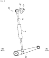
- FIG. 2 is a left side view showing a shift device according to a comparative example.
- an arrow FR indicates a vehicle front side
- an arrow RE indicates a vehicle rear side
- an arrow L indicates a vehicle left side
- an arrow R indicates a vehicle right side.
- a straddle-type vehicle 1 is configured by mounting various components such as an engine 30 and an electrical system on a twin spar type vehicle body frame 10 formed by aluminum casting.
- the vehicle body frame 10 includes a pair of main frames 12 that are branched off from a head pipe 11 to the left and right and extend rearward, and a pair of down frames 13 that are branched off from the head pipe 11 to the left and right and extend downward.
- a rear portion of the engine 30 is supported by the pair of main frames 12, and a front portion of the engine 30 is supported by the pair of down frames 13. Since the engine 30 is supported by the vehicle body frame 10, rigidity of the entire vehicle is ensured.
- a front portion of the main frame 12 serves as a tank rail 14 located above the engine 30, and a fuel tank 16 is supported by the tank rail 14.
- a rear portion of the main frame 12 serves as a body frame 15 located at a rear side of the engine 30, and a swing arm 17 is swingably supported at a substantially intermediate position in an upper-lower direction of the body frame 15.
- the swing arm 17 is coupled to an upper portion of the body frame 15 via a link plate 18 and a rear suspension 19.
- a seat rail 21 and a back stay 22 extend rearward from the upper portion of the body frame 15, and a rider seat 23 is supported on the seat rail 21.
- a pair of front forks 24 are supported by the head pipe 11, and a front wheel 25 is rotatably supported by lower ends of the front forks 24.
- the swing arm 17 extends rearward from the body frame 15, and a rear wheel 26 is rotatably supported by a rear end of the swing arm 17.
- the engine 30 is coupled to the rear wheel 26 via a chain drive type transmission mechanism, and power of the engine 30 is transmitted to the rear wheel 26 via the transmission mechanism.
- Footrests 28 are provided on the body frame 15 via footrest brackets 27.
- a shift device 50 is provided between a lower portion of the engine 30 and the left footrest 28.
- a shift sensor 92 can be attached to a shift rod 91 by ensuring a length of the shift rod 91 of the shift device 90 in a vertical direction.
- a shift lever 93 is coupled to a lower end of the shift rod 91, and a shift shaft 95 is coupled to an upper end of the shift rod 91 via a link arm 94.
- a shift operation of the shift lever 93 is transmitted to the shift shaft 95, and the shift shaft 95 is rotated to cause the transmission mechanism to perform a shift change.
- a shift rod 57 of the shift device 50 cannot be directed vertically, and a sufficient length cannot be ensured (see FIG. 3 ).
- the body frame 15 is positioned at a rear side of the engine 30, and the shift rod 57 needs to extend rearward in order to attach a shift sensor on the shift rod 57.
- the shift rod 57 is extended, the entire shift device 50 is increased in size, and it is difficult to ensure a minimum ground clearance, a bank angle, and the like. Therefore, the shift rod 57 is shortened by using a shift sensor 60 having a link arm shape in the present embodiment, and miniaturization is achieved by a concentrated arrangement of respective members of the shift device 50.
- FIG. 3 is a left side view showing a periphery of the engine according to the present embodiment.
- FIG. 4 is a bottom view showing a periphery of the engine according to the present embodiment.
- FIGS. 3 and 4 show a state where a sprocket cover is removed from the engine.
- the engine 30 includes a crankcase 31 having an upper-lower divided structure that includes an upper case 32 and a lower case 33.
- the upper case 32 is integrated with a cylinder, and a cylinder head 34 and a cylinder head cover (not shown) are attached to an upper portion of the upper case 32.
- a valve gear (not shown) for operating intake and exhaust valves is accommodated inside the cylinder head 34 and the cylinder head cover.
- An oil pan 35 that stores oil for lubrication and cooling is attached to a lower portion of the lower case 33.
- a magneto cover 36 that covers a magneto (not shown) from a side is attached to a left side surface of the crankcase 31.
- a crankshaft 41 is disposed inside the magneto cover 36, and a counter shaft 42 and a drive shaft 43 are disposed in parallel with the crankshaft 41 at a rear side of the crankshaft 41. In this manner, the crankshaft 41, the counter shaft 42, and the drive shaft 43 are arranged side by side in the front-rear direction.
- a water pump 44 is disposed below the counter shaft 42, and a shift cam 45 is disposed below the drive shaft 43 in parallel with the drive shaft 43.
- a shift shaft 51 is disposed at a rear side of the shift cam 45 in parallel with the shift cam 45, and the shift sensor 60 is attached to one end of a shift shaft 51 protruding from a left side surface of the lower case 33 so as to be integrally rotatable with the shift shaft 51.
- the shift sensor 60 is disposed below the drive shaft 43 and is disposed between the water pump 44 and the body frame 15.
- the shift sensor 60 is positioned above a lower end of the water pump 44 and is positioned inside the magneto cover 36 in a vehicle width direction (particularly, see FIG. 4 ). Since the water pump 44 is disposed in a manner of covering the shift sensor 60 from the front side, the shift sensor 60 is effectively protected by the water pump 44 from flying objects such as flying stones from the front side.
- a lead wire 74 extends obliquely upward from a front surface of the shift sensor 60, and the lead wire 74 is not entangled with an operation portion 56 of a shift lever 52 at a rear side of the shift sensor 60.
- the footrest bracket 27 is attached to a rear edge of the body frame 15, and the shift lever 52 is attached to the footrest bracket 27 in a manner of being coaxial with the footrest 28.
- the shift lever 52 is formed with a long arm 53 and a short arm 54 so as to be a substantially L shape in a side view.
- An attachment portion 55 (see FIG. 5 ) that is swingably supported by the footrest bracket 27 is formed at a bent portion of the shift lever 52.
- the long arm 53 extends obliquely downward toward a front side from the attachment portion 55, and the operation portion 56 that receives a shift operation is provided at a tip end of the long arm 53.
- a tip end side of the long arm 53 overlaps with the body frame 15 in a vehicle side view.
- the short arm 54 extends substantially downward from the attachment portion 55, and a rear end of the shift rod 57 is coupled to a tip end of the short arm 54 via a joint 58.
- the shift rod 57 extends obliquely upward toward the front side from the joint 58 and crosses an outer side of the body frame 15 in the vehicle width direction.
- An upper portion of the shift sensor 60 is coupled to a front end of the shift rod 57 via a joint 59.
- the shift sensor 60, the shift lever 52, and the shift rod 57 are positioned below the drive shaft 43 and the swing arm 17 and above the lower end of the water pump 44. In this manner, respective members of the shift device 50 are disposed in a compact manner at a vehicle lower side.
- the shift shaft 51 when the shift lever 52 is operated by a driver, the shift shaft 51 is integrally rotated by a predetermined angle with the shift sensor 60 via the shift rod 57.
- the rotation of the shift shaft 51 is transmitted to the shift cam 45, and the shift cam 45 is rotated by a predetermined angle, so that a shift fork (not shown) changes a combination of transmission gears of the counter shaft 42 and the drive shaft 43 so as to perform a shift change.
- a shift operation on the shift lever 52 in accordance with a movement of the shift rod 57 is detected by the shift sensor 60, and the shift change can be performed without performing a clutch operation.
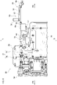
- FIG. 5 is a left side view showing the shift device according to the present embodiment.
- FIG. 6 is a right side view showing the shift device according to the present embodiment.
- FIG. 7 is a front view showing the shift shaft according to the present embodiment.
- the shift device 50 includes the shift sensor 60 that detects a shift operation on the shift lever 52.
- a sensor main body 61 of the shift sensor 60 is formed into a triangular shape with rounded corners in a side view.
- a Hall integrated circuit (IC) 63 serving as a detection portion is provided on an outer side surface 62 at an outer side in the vehicle width direction of the sensor main body 61, and a pair of protection portions 64 and 65 are provided in a manner of sandwiching the Hall IC 63 from above and below.
- the Hall IC 63 detects a movement of the shift rod 57 in accordance with the shift operation on the shift lever 52.
- the lead wire 74 extends from a front end of the Hall IC 63 toward a control device (not shown).
- the pair of protection portions 64 and 65 protect the Hall IC 63 from external forces from above and below.
- the Hall IC 63 protrudes outward in the vehicle width direction from the outer side surface 62 of the sensor main body 61, and the pair of protection portions 64 and 65 are increased in protruding amounts from an upper portion and a lower portion of the sensor main body 61 toward an outer side in the vehicle width direction as coming close to the Hall IC 63. That is, an outer surface of the upper protection portion 64 is inclined downward toward the outer side in the vehicle width direction, and an outer surface of the lower protection portion 65 is inclined upward toward the outer side in the vehicle width direction. Even when an external force is applied to the protection portions 64 and 65 from above or below by a foot of a driver, the external force is deflected outward in the vehicle width direction, and the Hall IC 63 is effectively protected.
- a holding portion 67 that holds the shift shaft 51 and a fastening boss 68 that is continuous with a front side of the holding portion 67 are provided at an inner side of the sensor main body 61 in the vehicle width direction in an inner side surface view.
- An opening is formed in the holding portion 67 at a substantially central position of the sensor main body 61 in a vehicle side view, and a female serration 69 is attached to the opening.
- a slit 71 is formed so as to divide the fastening boss 68 from a fitting hole of the female serration 69 toward an outer side in a radial direction.
- lower portion of the holding portion 67 and the fastening boss 68 is coupled to an inner side surface 66 of the sensor main body 61, and upper portion of the holding portion 67 and the fastening boss 68 is separated from the inner side surface 66 of the sensor main body 61.
- a male serration of the shift shaft 51 is inserted into the female serration 69, and a tip end of the shift shaft 51 is brought into contact with a contact surface 72 of the sensor main body 61 so as to position the shift shaft 51.
- the contact surface 72 of the sensor main body 61 is one step higher than the inner side surface 66 of the sensor main body 61.
- the fastening boss 68 extends to a lower end of the sensor main body 61, and a bolt 73 is fastened to the fastening boss 68 from a lower side of the fastening boss 68.
- the bolt 73 is fastened to the fastening boss 68, a slit width is narrowed, and the shift shaft 51 is held by the female serration 69 of the holding portion 67. Accordingly, the shift sensor 60 is attached to the shift shaft 51 so as to be integrally rotatable with the shift shaft 51.
- the shift sensor 60 is inclined such that a front side of a lower end of the shift sensor 60 is positioned above a rear side thereof. That is, the shift sensor 60 is slightly inclined rearward about the shift shaft 51.
- the fastening boss 68 is formed at a front side of the shift sensor 60, it is easy to see a head portion of the bolt 73 from the front side, and the bolt 73 is easily fastened to the fastening boss 68.
- the front end of the shift rod 57 is coupled to the upper portion of the sensor main body 61 via the joint 59.
- the shift shaft 51 is held at a substantially central portion of the sensor main body 61, and the shift rod 57 is coupled to the upper portion of the sensor main body 61, so that the sensor main body 61 functions as a link arm that couples the shift shaft 51 and the shift rod 57.
- the shift sensor 60 is not provided on the shift rod 57, it is not necessary to ensure a long shift rod 57 in order to attach the shift sensor 60. Since the shift sensor 60 is used instead of a link arm, the number of components is suppressed from increasing, and the shift sensor 60 is easily attached.
- the long arm 53 extends obliquely downward toward a front side from the attachment portion 55 serving as a swing fulcrum, and the short arm 54 extends substantially downward from the attachment portion 55.
- the long arm 53 extends toward a lower end of the shift sensor 60, and the operation portion 56 at a tip end of the long arm 53 is positioned at a rear side of the shift sensor 60.
- the shift rod 57 extends from the joint 58 at a tip end of the short arm 54 to the joint 59 at an upper portion of the shift sensor 60.
- the long arm 53 crosses an outer side of the shift rod 57 in the vehicle width direction, and the long arm 53 and the shift rod 57 obliquely intersect with each other.
- inclination of the short arm 54 substantially coincides with inclination of the shift sensor 60.
- the shift rod 57 extends in a direction orthogonal to the inclination of the short arm 54 and the shift sensor 60, and a distance L1 from a front end of the shift sensor 60 to a front end of the operation portion 56 in an extending direction of the shift rod 57 is equal to or less than half of a length L2 of the shift rod 57. Accordingly, the operation portion 56 is brought close to the shift sensor 60, and a front-rear length of the shift device 50 is reduced. Since the front-rear length of the shift device 50 is reduced, a step position is not biased in the front-rear direction, and a riding position of the driver is not impaired.
- the operation portion 56 and the shift sensor 60 are provided below the shift rod 57, and the operation portion 56 and a lower portion of the shift sensor 60 are positioned at the same height. As a result, the operating portion 56 is not positioned too low, and a bank angle can be easily ensured. Since the shift sensor 60 is disposed below the shift rod 57, the shift shaft 51 that rotates integrally with the shift sensor 60 is separated from the drive shaft 43 (see FIG. 3 ) of the transmission device. Therefore, the degree of freedom of a shaft arrangement of the transmission device is improved, the shift device 50 is separated from a drive chain, and it is easy to arrange the sprocket cover 29 (see FIG. 1 ).
- the attachment portion 55 of the shift lever 52 is provided above the shift rod 57, and the attachment portion 55 and an upper portion of the shift sensor 60 are positioned at the same height.
- a rear end of the shift rod 57 is positioned below a front end of the shift rod 57, and the joint 58 at the rear end of the shift rod 57 is positioned at the same height as a lower portion of the shift sensor 60 and the operation portion 56. Since the shift lever 52 and the shift rod 57 are accommodated in a range from the upper portion to the lower portion of the shift sensor 60, a height of the shift device 50 is reduced.
- the long arm 53 extends obliquely from the attachment portion 55 toward the operation portion 56, and a sufficient length of the shift lever 52 is ensured.
- the shift lever 52 and the shift rod 57 are disposed in a compact manner so as to intersect with each other, so that a front-rear length and a height of the shift device 50 are reduced, and the shift device 50 is reduced in size.
- the operation portion 56, the lower portion of the shift sensor 60, and the joint 58 at the rear end of the shift rod 57 do not need to be positioned at completely the same height. A slight deviation may be generated to such an extent that these heights are considered to be the same height.
- the attachment portion 55 and the upper portion of the shift sensor 60 do not need to be positioned at completely the same height. A slight deviation may be generated to such an extent that these heights are considered to be the same height.
- the shift sensor 60 has a function of detecting a shift operation, and the shift sensor 60 functions as a link arm that couples the shift shaft 51 and the shift rod 57. Even in a layout in which a sufficient length of the shift rod 57 cannot be ensured, the shift sensor 60 can be provided in the shift device 50. Since the shift sensor 60 and the operation portion 56 are positioned below the shift rod 57, the shift lever 52 and the shift rod 57 are disposed in a compact manner in the same space, and the shift device 50 is reduced in size. In addition, since the shift sensor 60 is provided instead of a link arm, the number of components is suppressed from increasing, and the shift sensor 60 is easily attached.
- the operation portion and the shift sensor are positioned below the shift rod in the present embodiment, the operation portion and the shift sensor may be positioned at the same side in a manner of sandwiching the shift rod.
- the operation portion and the shift sensor may be positioned above the shift rod.
- the Hall IC is used as a sensor portion in the present embodiment, the sensor portion is not limited to the Hall IC.
- the sensor portion may be, for example, an anisotropic magneto resistive (AMR) sensor as long as the sensor portion can detect a movement of the shift rod.
- AMR anisotropic magneto resistive
- the shift sensor is provided with a pair of protection portions that protect the sensor portion from external forces from above and below in the present embodiment, the shift sensor may be provided with one protection portion so as to protect the sensor portion from external forces at least one of from above and from below. Further, the shift sensor may not be provided with a protection portion.
- the shift sensor is inclined rearward such that the front side of the lower end of the shift sensor is positioned above the rear side thereof in the present embodiment, the shift sensor may not be inclined, and the shift sensor may be inclined forward.
- a positional relationship among the operation portion, the lower portion of the shift sensor, and the rear end of the shift rod is not particularly limited.
- a positional relationship between the attachment portion of the shift lever and the upper portion of the shift sensor is not particularly limited.
- the distance from the front end of the shift sensor to the front end of the operation portion in the extending direction of the shift rod is equal to or less than half of the length of the shift rod in the present embodiment
- the distance from the front end of the shift sensor to the front end of the operation portion is not particularly limited. As long as the length of the shift lever can be ensured, the distance from the front end of the shift sensor to the front end of the operation portion may be larger than half of the length of the shift rod.
- the integrally rotatable configuration is not limited to a configuration in which rotation is transmitted from the shift shaft to the shift sensor without a play.
- the integrally rotatable configuration may be a configuration in which rotation is transmitted from the shift shaft to the shift sensor with a play of a predetermined rotation amount.
- the shift device may be applied not only to the straddle-type vehicle shown in the drawings but also to a straddle-type vehicle of other types.
- the straddle-type vehicle is not limited to general vehicles on which a rider rides in a posture of straddling a seat, and also includes a small-sized scooter-type vehicle on which a rider rides without straddling a seat.
- the shift device (50) is a shift device for a straddle-type vehicle (1) that is configured to cause a transmission device to perform a shift change in accordance with rotation of a shift shaft (51).
- the shift device (50) includes a shift lever (52) provided with an operation portion (56) that is configured to receive a shift operation, a shift sensor (60) provided on the shift shaft so as to be integrally rotatable with the shift shaft, and a shift rod (57) that couples the shift lever and the shift sensor.
- the shift sensor is configured to detect the shift operation on the shift lever in accordance with a movement of the shift rod, and the operation portion and the shift sensor are positioned at the same side in a manner of sandwiching the shift rod in a vehicle side view.
- the shift sensor has a function of detecting the shift operation, and the shift sensor functions as a link arm that couples the shift shaft and the shift rod. Even in a layout in which a sufficient length of the shift rod cannot be ensured, the shift sensor can be provided in the shift device. Since the shift sensor and the operation portion are positioned at the same side in a manner of sandwiching the shift rod, the shift lever and the shift rod are disposed in a compact manner in the same space, and the shift device is reduced in size. In addition, since the shift sensor is provided instead of a link arm, the number of components is suppressed from increasing, and the shift sensor is easily attached.
- the operation portion is positioned at a rear side of the shift sensor in the vehicle side view, and a distance from a front end of the shift sensor to a front end of the operation portion in an extending direction of the shift rod is equal to or less than half of a length of the shift rod. According to this configuration, since the operation portion is brought close to the shift sensor, a front-rear length of the shift device can be reduced. Since the front-rear length of the shift device is reduced, a step position is not biased in the front-rear direction, and a riding position of a driver is not impaired.
- the shift rod extends in a front-rear direction, and the operation portion and the shift sensor are positioned below the shift rod. According to this configuration, a height of the shift device can be reduced. Since the shift sensor is disposed below the shift rod, the shift shaft that rotates integrally with the shift sensor is separated from a drive shaft (43) of the transmission device. Therefore, the degree of freedom of a shaft arrangement of the transmission device is improved, the shift device is separated from a drive chain, and it is easy to arrange a sprocket cover (29).
- the operation portion and a lower portion of the shift sensor are positioned at the same height. According to this configuration, a height of the shift device can be reduced. The shift device is not positioned too low, and a bank angle can be easily ensured.
- an attachment portion (55) of the shift lever to a vehicle is positioned above the shift rod, and the attachment portion of the shift lever and an upper portion of the shift sensor are positioned at the same height. According to this configuration, a height of the shift device can be reduced.
- the shift lever extends obliquely downward from the attachment portion toward the operation portion, and a sufficient length of the shift lever is ensured.
- one end of the shift rod is coupled to an upper portion of the shift sensor, the other end of the shift rod is positioned below the one end of the shift rod, and a lower portion of the shift sensor and the other end of the shift rod are positioned at the same height.
- the shift rod is accommodated in a range from the upper portion to the lower portion of the shift sensor, and the height of the shift device can be reduced.
- a water pump (44) is disposed in a manner of covering the shift sensor from a front side. According to this configuration, the shift sensor can be protected from flying objects such as flying stones from the front side.
Landscapes
- Engineering & Computer Science (AREA)
- General Engineering & Computer Science (AREA)
- Mechanical Engineering (AREA)
- Chemical & Material Sciences (AREA)
- Combustion & Propulsion (AREA)
- Transportation (AREA)
- Arrangement Or Mounting Of Control Devices For Change-Speed Gearing (AREA)
- Gear-Shifting Mechanisms (AREA)
Abstract
Description
- The present invention relates to a shift device.
- As a shift device for a straddle-type vehicle, there is known a shift device employing a quick shift that can detect a shift operation by a driver and perform a shift change without performing a clutch operation (for example, see Patent Literature 1). In the shift device described in
Patent Literature 1, one end of a shift shaft protrudes from an upper side surface of a crankcase, and a shift lever extends rearward from a lower side surface of the crankcase. An upper end of a shift rod is coupled to one end of the shift shaft via a link arm, and a lower end of the shift rod is coupled to an intermediate position of the shift lever. A shift sensor is integrally provided on the shift rod that is long in an upper-lower direction, and a shift operation in accordance with an operation load applying to the shift rod is detected. - Patent Literature 1:
Japanese Patent No. 6107621 - In order to provide the shift sensor integrally with the shift rod, it is necessary to ensure a sufficient length of the shift rod. Therefore, it is difficult to provide the shift sensor depending on a layout of the straddle-type vehicle.
- The present invention has been made in view of the above circumstances, and an object of the present invention is to provide a compact shift device in which a shift sensor can be disposed even in a layout in which a sufficient length of a shift rod cannot be ensured.
- There is provided a shift device for a straddle-type vehicle that is configured to cause a transmission device to perform a shift change in accordance with rotation of a shift shaft. The shift device includes: a shift lever provided with an operation portion that is configured to receive a shift operation; a shift sensor provided on the shift shaft so as to be integrally rotatable with the shift shaft; and a shift rod that couples the shift lever and the shift sensor. The shift sensor is configured to detect the shift operation on the shift lever in accordance with a movement of the shift rod. The operation portion and the shift sensor are positioned at the same side in a manner of sandwiching the shift rod in a vehicle side view.
- In the shift device according to an aspect of the present invention, the shift sensor has a function of detecting the shift operation, and the shift sensor functions as a link arm that couples the shift shaft and the shift rod. Even in a layout in which a sufficient length of the shift rod cannot be ensured, the shift sensor can be provided in the shift device. Since the shift sensor and the operation portion are positioned at the same side in a manner of sandwiching the shift rod, the shift lever and the shift rod are disposed in a compact manner in the same space, and the shift device is reduced in size. In addition, since the shift sensor is provided instead of a link arm, the number of components is suppressed from increasing, and the shift sensor is easily attached.
-
-
FIG. 1 is a left side view showing a straddle-type vehicle according to the present embodiment. -
FIG. 2 is a left side view showing a shift device according to a comparative example. -
FIG. 3 is a left side view showing a periphery of an engine according to the present embodiment. -
FIG. 4 is a bottom view showing the periphery of the engine according to the present embodiment. -
FIG. 5 is a left side view showing a shift device according to the present embodiment. -
FIG. 6 is a right side view showing the shift device according to the present embodiment. -
FIG. 7 is a front view showing a shift shaft according to the present embodiment. - A shift device according to an aspect of the present invention causes a transmission device to perform a shift change in accordance with rotation of a shift shaft of a straddle-type vehicle. The shift lever is provided with an operation portion that receives a shift operation, a shift sensor is provided on the shift shaft so as to be integrally rotatable with the shift shaft, and the shift lever and the shift sensor are coupled to each other via a shift rod. The shift sensor detects a shift operation on the shift lever in accordance with a movement of the shift rod. The shift sensor has a function of detecting the shift operation, and the shift sensor functions as a link arm that couples the shift shaft and the shift rod. Even in a layout in which a sufficient length of the shift rod cannot be ensured, the shift sensor can be provided in the shift device. Since the operation portion and the shift sensor are positioned at the same side in a manner of sandwiching the shift rod in a vehicle side view, the shift lever and the shift rod are disposed in a compact manner in the same space, and the shift device is reduced in size. In addition, since the shift sensor is provided instead of a link arm, the number of components is suppressed from increasing, and the shift sensor is easily attached.
- Hereinafter, a present embodiment will be described in detail with reference to the accompanying drawings.
FIG. 1 is a left side view showing a straddle-type vehicle according to the present embodiment.FIG. 2 is a left side view showing a shift device according to a comparative example. In the following drawings, an arrow FR indicates a vehicle front side, an arrow RE indicates a vehicle rear side, an arrow L indicates a vehicle left side, and an arrow R indicates a vehicle right side. - As shown in
FIG. 1 , a straddle-type vehicle 1 is configured by mounting various components such as anengine 30 and an electrical system on a twin spar typevehicle body frame 10 formed by aluminum casting. Thevehicle body frame 10 includes a pair ofmain frames 12 that are branched off from ahead pipe 11 to the left and right and extend rearward, and a pair ofdown frames 13 that are branched off from thehead pipe 11 to the left and right and extend downward. A rear portion of theengine 30 is supported by the pair ofmain frames 12, and a front portion of theengine 30 is supported by the pair ofdown frames 13. Since theengine 30 is supported by thevehicle body frame 10, rigidity of the entire vehicle is ensured. - A front portion of the
main frame 12 serves as atank rail 14 located above theengine 30, and afuel tank 16 is supported by thetank rail 14. A rear portion of themain frame 12 serves as abody frame 15 located at a rear side of theengine 30, and aswing arm 17 is swingably supported at a substantially intermediate position in an upper-lower direction of thebody frame 15. Theswing arm 17 is coupled to an upper portion of thebody frame 15 via alink plate 18 and arear suspension 19. Aseat rail 21 and aback stay 22 extend rearward from the upper portion of thebody frame 15, and arider seat 23 is supported on theseat rail 21. - A pair of
front forks 24 are supported by thehead pipe 11, and afront wheel 25 is rotatably supported by lower ends of thefront forks 24. Theswing arm 17 extends rearward from thebody frame 15, and arear wheel 26 is rotatably supported by a rear end of theswing arm 17. Theengine 30 is coupled to therear wheel 26 via a chain drive type transmission mechanism, and power of theengine 30 is transmitted to therear wheel 26 via the transmission mechanism.Footrests 28 are provided on thebody frame 15 viafootrest brackets 27. Ashift device 50 is provided between a lower portion of theengine 30 and theleft footrest 28. - As shown in the comparative example in
FIG. 2 , when three major axes of the engine are arranged in a triangular shape, an arrangement space of ashift device 90 can be ensured in a height direction. In such an engine, ashift sensor 92 can be attached to ashift rod 91 by ensuring a length of theshift rod 91 of theshift device 90 in a vertical direction. Ashift lever 93 is coupled to a lower end of theshift rod 91, and ashift shaft 95 is coupled to an upper end of theshift rod 91 via alink arm 94. A shift operation of theshift lever 93 is transmitted to theshift shaft 95, and theshift shaft 95 is rotated to cause the transmission mechanism to perform a shift change. - In the
engine 30 according to the present embodiment, since the three major axes are arranged in a front-rear direction, ashift rod 57 of theshift device 50 cannot be directed vertically, and a sufficient length cannot be ensured (seeFIG. 3 ). Thebody frame 15 is positioned at a rear side of theengine 30, and theshift rod 57 needs to extend rearward in order to attach a shift sensor on theshift rod 57. When theshift rod 57 is extended, theentire shift device 50 is increased in size, and it is difficult to ensure a minimum ground clearance, a bank angle, and the like. Therefore, theshift rod 57 is shortened by using ashift sensor 60 having a link arm shape in the present embodiment, and miniaturization is achieved by a concentrated arrangement of respective members of theshift device 50. - An arrangement configuration of the shift device will be described with reference to
FIGS. 3 and4 .FIG. 3 is a left side view showing a periphery of the engine according to the present embodiment.FIG. 4 is a bottom view showing a periphery of the engine according to the present embodiment.FIGS. 3 and4 show a state where a sprocket cover is removed from the engine. - As shown in
FIGS. 3 and4 , theengine 30 includes acrankcase 31 having an upper-lower divided structure that includes anupper case 32 and alower case 33. Theupper case 32 is integrated with a cylinder, and acylinder head 34 and a cylinder head cover (not shown) are attached to an upper portion of theupper case 32. A valve gear (not shown) for operating intake and exhaust valves is accommodated inside thecylinder head 34 and the cylinder head cover. Anoil pan 35 that stores oil for lubrication and cooling is attached to a lower portion of thelower case 33. Amagneto cover 36 that covers a magneto (not shown) from a side is attached to a left side surface of thecrankcase 31. - A
crankshaft 41 is disposed inside themagneto cover 36, and acounter shaft 42 and adrive shaft 43 are disposed in parallel with thecrankshaft 41 at a rear side of thecrankshaft 41. In this manner, thecrankshaft 41, thecounter shaft 42, and thedrive shaft 43 are arranged side by side in the front-rear direction. Awater pump 44 is disposed below thecounter shaft 42, and ashift cam 45 is disposed below thedrive shaft 43 in parallel with thedrive shaft 43. Further, ashift shaft 51 is disposed at a rear side of theshift cam 45 in parallel with theshift cam 45, and theshift sensor 60 is attached to one end of ashift shaft 51 protruding from a left side surface of thelower case 33 so as to be integrally rotatable with theshift shaft 51. - The
shift sensor 60 is disposed below thedrive shaft 43 and is disposed between thewater pump 44 and thebody frame 15. Theshift sensor 60 is positioned above a lower end of thewater pump 44 and is positioned inside themagneto cover 36 in a vehicle width direction (particularly, seeFIG. 4 ). Since thewater pump 44 is disposed in a manner of covering theshift sensor 60 from the front side, theshift sensor 60 is effectively protected by thewater pump 44 from flying objects such as flying stones from the front side. Alead wire 74 extends obliquely upward from a front surface of theshift sensor 60, and thelead wire 74 is not entangled with anoperation portion 56 of ashift lever 52 at a rear side of theshift sensor 60. - The
footrest bracket 27 is attached to a rear edge of thebody frame 15, and theshift lever 52 is attached to thefootrest bracket 27 in a manner of being coaxial with thefootrest 28. Theshift lever 52 is formed with along arm 53 and ashort arm 54 so as to be a substantially L shape in a side view. An attachment portion 55 (seeFIG. 5 ) that is swingably supported by thefootrest bracket 27 is formed at a bent portion of theshift lever 52. Thelong arm 53 extends obliquely downward toward a front side from theattachment portion 55, and theoperation portion 56 that receives a shift operation is provided at a tip end of thelong arm 53. A tip end side of thelong arm 53 overlaps with thebody frame 15 in a vehicle side view. - The
short arm 54 extends substantially downward from theattachment portion 55, and a rear end of theshift rod 57 is coupled to a tip end of theshort arm 54 via a joint 58. Theshift rod 57 extends obliquely upward toward the front side from the joint 58 and crosses an outer side of thebody frame 15 in the vehicle width direction. An upper portion of theshift sensor 60 is coupled to a front end of theshift rod 57 via a joint 59. Theshift sensor 60, theshift lever 52, and theshift rod 57 are positioned below thedrive shaft 43 and theswing arm 17 and above the lower end of thewater pump 44. In this manner, respective members of theshift device 50 are disposed in a compact manner at a vehicle lower side. - In the
shift device 50, when theshift lever 52 is operated by a driver, theshift shaft 51 is integrally rotated by a predetermined angle with theshift sensor 60 via theshift rod 57. The rotation of theshift shaft 51 is transmitted to theshift cam 45, and theshift cam 45 is rotated by a predetermined angle, so that a shift fork (not shown) changes a combination of transmission gears of thecounter shaft 42 and thedrive shaft 43 so as to perform a shift change. At this time, a shift operation on theshift lever 52 in accordance with a movement of theshift rod 57 is detected by theshift sensor 60, and the shift change can be performed without performing a clutch operation. - A detailed configuration of the shift device will be described with reference to
FIGS. 5 to 7 .FIG. 5 is a left side view showing the shift device according to the present embodiment.FIG. 6 is a right side view showing the shift device according to the present embodiment.FIG. 7 is a front view showing the shift shaft according to the present embodiment. - As shown in
FIGS. 5 and6 , theshift device 50 includes theshift sensor 60 that detects a shift operation on theshift lever 52. A sensormain body 61 of theshift sensor 60 is formed into a triangular shape with rounded corners in a side view. A Hall integrated circuit (IC) 63 serving as a detection portion is provided on anouter side surface 62 at an outer side in the vehicle width direction of the sensormain body 61, and a pair ofprotection portions Hall IC 63 from above and below. TheHall IC 63 detects a movement of theshift rod 57 in accordance with the shift operation on theshift lever 52. Thelead wire 74 extends from a front end of theHall IC 63 toward a control device (not shown). - The pair of
protection portions Hall IC 63 from external forces from above and below. TheHall IC 63 protrudes outward in the vehicle width direction from theouter side surface 62 of the sensormain body 61, and the pair ofprotection portions main body 61 toward an outer side in the vehicle width direction as coming close to theHall IC 63. That is, an outer surface of theupper protection portion 64 is inclined downward toward the outer side in the vehicle width direction, and an outer surface of thelower protection portion 65 is inclined upward toward the outer side in the vehicle width direction. Even when an external force is applied to theprotection portions Hall IC 63 is effectively protected. - As shown in
FIGS. 6 and7 , a holdingportion 67 that holds theshift shaft 51 and afastening boss 68 that is continuous with a front side of the holdingportion 67 are provided at an inner side of the sensormain body 61 in the vehicle width direction in an inner side surface view. An opening is formed in the holdingportion 67 at a substantially central position of the sensormain body 61 in a vehicle side view, and afemale serration 69 is attached to the opening. Aslit 71 is formed so as to divide thefastening boss 68 from a fitting hole of thefemale serration 69 toward an outer side in a radial direction. With a straight line S on theslit 71 interposed therebetween, lower portion of the holdingportion 67 and thefastening boss 68 is coupled to aninner side surface 66 of the sensormain body 61, and upper portion of the holdingportion 67 and thefastening boss 68 is separated from theinner side surface 66 of the sensormain body 61. - A male serration of the
shift shaft 51 is inserted into thefemale serration 69, and a tip end of theshift shaft 51 is brought into contact with acontact surface 72 of the sensormain body 61 so as to position theshift shaft 51. Thecontact surface 72 of the sensormain body 61 is one step higher than theinner side surface 66 of the sensormain body 61. Thefastening boss 68 extends to a lower end of the sensormain body 61, and abolt 73 is fastened to thefastening boss 68 from a lower side of thefastening boss 68. When thebolt 73 is fastened to thefastening boss 68, a slit width is narrowed, and theshift shaft 51 is held by thefemale serration 69 of the holdingportion 67. Accordingly, theshift sensor 60 is attached to theshift shaft 51 so as to be integrally rotatable with theshift shaft 51. - Since the
bolt 73 is fastened from a lower side of the vehicle by a tool, a tool line is ensured without affecting a layout of other components such as thewater pump 44. In a non-operated state of the shift device 50 (the shift lever 52), theshift sensor 60 is inclined such that a front side of a lower end of theshift sensor 60 is positioned above a rear side thereof. That is, theshift sensor 60 is slightly inclined rearward about theshift shaft 51. As described above, since thefastening boss 68 is formed at a front side of theshift sensor 60, it is easy to see a head portion of thebolt 73 from the front side, and thebolt 73 is easily fastened to thefastening boss 68. - The front end of the
shift rod 57 is coupled to the upper portion of the sensormain body 61 via the joint 59. In this manner, theshift shaft 51 is held at a substantially central portion of the sensormain body 61, and theshift rod 57 is coupled to the upper portion of the sensormain body 61, so that the sensormain body 61 functions as a link arm that couples theshift shaft 51 and theshift rod 57. Since theshift sensor 60 is not provided on theshift rod 57, it is not necessary to ensure along shift rod 57 in order to attach theshift sensor 60. Since theshift sensor 60 is used instead of a link arm, the number of components is suppressed from increasing, and theshift sensor 60 is easily attached. - As shown in
FIGS. 5 and6 , in theshift lever 52, thelong arm 53 extends obliquely downward toward a front side from theattachment portion 55 serving as a swing fulcrum, and theshort arm 54 extends substantially downward from theattachment portion 55. Thelong arm 53 extends toward a lower end of theshift sensor 60, and theoperation portion 56 at a tip end of thelong arm 53 is positioned at a rear side of theshift sensor 60. Theshift rod 57 extends from the joint 58 at a tip end of theshort arm 54 to the joint 59 at an upper portion of theshift sensor 60. Thelong arm 53 crosses an outer side of theshift rod 57 in the vehicle width direction, and thelong arm 53 and theshift rod 57 obliquely intersect with each other. - In a non-operated state of the
shift lever 52, inclination of theshort arm 54 substantially coincides with inclination of theshift sensor 60. Theshift rod 57 extends in a direction orthogonal to the inclination of theshort arm 54 and theshift sensor 60, and a distance L1 from a front end of theshift sensor 60 to a front end of theoperation portion 56 in an extending direction of theshift rod 57 is equal to or less than half of a length L2 of theshift rod 57. Accordingly, theoperation portion 56 is brought close to theshift sensor 60, and a front-rear length of theshift device 50 is reduced. Since the front-rear length of theshift device 50 is reduced, a step position is not biased in the front-rear direction, and a riding position of the driver is not impaired. - In a vehicle side view, the
operation portion 56 and theshift sensor 60 are provided below theshift rod 57, and theoperation portion 56 and a lower portion of theshift sensor 60 are positioned at the same height. As a result, the operatingportion 56 is not positioned too low, and a bank angle can be easily ensured. Since theshift sensor 60 is disposed below theshift rod 57, theshift shaft 51 that rotates integrally with theshift sensor 60 is separated from the drive shaft 43 (seeFIG. 3 ) of the transmission device. Therefore, the degree of freedom of a shaft arrangement of the transmission device is improved, theshift device 50 is separated from a drive chain, and it is easy to arrange the sprocket cover 29 (seeFIG. 1 ). - In a vehicle side view, the
attachment portion 55 of theshift lever 52 is provided above theshift rod 57, and theattachment portion 55 and an upper portion of theshift sensor 60 are positioned at the same height. A rear end of theshift rod 57 is positioned below a front end of theshift rod 57, and the joint 58 at the rear end of theshift rod 57 is positioned at the same height as a lower portion of theshift sensor 60 and theoperation portion 56. Since theshift lever 52 and theshift rod 57 are accommodated in a range from the upper portion to the lower portion of theshift sensor 60, a height of theshift device 50 is reduced. Thelong arm 53 extends obliquely from theattachment portion 55 toward theoperation portion 56, and a sufficient length of theshift lever 52 is ensured. - In this manner, the
shift lever 52 and theshift rod 57 are disposed in a compact manner so as to intersect with each other, so that a front-rear length and a height of theshift device 50 are reduced, and theshift device 50 is reduced in size. Theoperation portion 56, the lower portion of theshift sensor 60, and the joint 58 at the rear end of theshift rod 57 do not need to be positioned at completely the same height. A slight deviation may be generated to such an extent that these heights are considered to be the same height. Similarly, theattachment portion 55 and the upper portion of theshift sensor 60 do not need to be positioned at completely the same height. A slight deviation may be generated to such an extent that these heights are considered to be the same height. - As described above, according to the present embodiment, the
shift sensor 60 has a function of detecting a shift operation, and theshift sensor 60 functions as a link arm that couples theshift shaft 51 and theshift rod 57. Even in a layout in which a sufficient length of theshift rod 57 cannot be ensured, theshift sensor 60 can be provided in theshift device 50. Since theshift sensor 60 and theoperation portion 56 are positioned below theshift rod 57, theshift lever 52 and theshift rod 57 are disposed in a compact manner in the same space, and theshift device 50 is reduced in size. In addition, since theshift sensor 60 is provided instead of a link arm, the number of components is suppressed from increasing, and theshift sensor 60 is easily attached. - Although the operation portion and the shift sensor are positioned below the shift rod in the present embodiment, the operation portion and the shift sensor may be positioned at the same side in a manner of sandwiching the shift rod. For example, the operation portion and the shift sensor may be positioned above the shift rod.
- Although the Hall IC is used as a sensor portion in the present embodiment, the sensor portion is not limited to the Hall IC. The sensor portion may be, for example, an anisotropic magneto resistive (AMR) sensor as long as the sensor portion can detect a movement of the shift rod.
- Although the shift sensor is provided with a pair of protection portions that protect the sensor portion from external forces from above and below in the present embodiment, the shift sensor may be provided with one protection portion so as to protect the sensor portion from external forces at least one of from above and from below. Further, the shift sensor may not be provided with a protection portion.
- Although the shift sensor is inclined rearward such that the front side of the lower end of the shift sensor is positioned above the rear side thereof in the present embodiment, the shift sensor may not be inclined, and the shift sensor may be inclined forward.
- Although the operation portion, the lower portion of the shift sensor, and the rear end of the shift rod are positioned at the same height in the present embodiment, a positional relationship among the operation portion, the lower portion of the shift sensor, and the rear end of the shift rod is not particularly limited.
- Although the attachment portion of the shift lever and the upper portion of the shift sensor are positioned at the same height in the present embodiment, a positional relationship between the attachment portion of the shift lever and the upper portion of the shift sensor is not particularly limited.
- Although the distance from the front end of the shift sensor to the front end of the operation portion in the extending direction of the shift rod is equal to or less than half of the length of the shift rod in the present embodiment, the distance from the front end of the shift sensor to the front end of the operation portion is not particularly limited. As long as the length of the shift lever can be ensured, the distance from the front end of the shift sensor to the front end of the operation portion may be larger than half of the length of the shift rod.
- Although the shift sensor is provided on the shift shaft so as to be integrally rotatable with the shift shaft in the present embodiment, the integrally rotatable configuration is not limited to a configuration in which rotation is transmitted from the shift shaft to the shift sensor without a play. The integrally rotatable configuration may be a configuration in which rotation is transmitted from the shift shaft to the shift sensor with a play of a predetermined rotation amount.
- The shift device may be applied not only to the straddle-type vehicle shown in the drawings but also to a straddle-type vehicle of other types. The straddle-type vehicle is not limited to general vehicles on which a rider rides in a posture of straddling a seat, and also includes a small-sized scooter-type vehicle on which a rider rides without straddling a seat.
- As described above, the shift device (50) according to the present embodiment is a shift device for a straddle-type vehicle (1) that is configured to cause a transmission device to perform a shift change in accordance with rotation of a shift shaft (51). The shift device (50) includes a shift lever (52) provided with an operation portion (56) that is configured to receive a shift operation, a shift sensor (60) provided on the shift shaft so as to be integrally rotatable with the shift shaft, and a shift rod (57) that couples the shift lever and the shift sensor. The shift sensor is configured to detect the shift operation on the shift lever in accordance with a movement of the shift rod, and the operation portion and the shift sensor are positioned at the same side in a manner of sandwiching the shift rod in a vehicle side view. According to this configuration, the shift sensor has a function of detecting the shift operation, and the shift sensor functions as a link arm that couples the shift shaft and the shift rod. Even in a layout in which a sufficient length of the shift rod cannot be ensured, the shift sensor can be provided in the shift device. Since the shift sensor and the operation portion are positioned at the same side in a manner of sandwiching the shift rod, the shift lever and the shift rod are disposed in a compact manner in the same space, and the shift device is reduced in size. In addition, since the shift sensor is provided instead of a link arm, the number of components is suppressed from increasing, and the shift sensor is easily attached.
- In the shift device according to the present embodiment, the operation portion is positioned at a rear side of the shift sensor in the vehicle side view, and a distance from a front end of the shift sensor to a front end of the operation portion in an extending direction of the shift rod is equal to or less than half of a length of the shift rod. According to this configuration, since the operation portion is brought close to the shift sensor, a front-rear length of the shift device can be reduced. Since the front-rear length of the shift device is reduced, a step position is not biased in the front-rear direction, and a riding position of a driver is not impaired.
- In the shift device according to the present embodiment, the shift rod extends in a front-rear direction, and the operation portion and the shift sensor are positioned below the shift rod. According to this configuration, a height of the shift device can be reduced. Since the shift sensor is disposed below the shift rod, the shift shaft that rotates integrally with the shift sensor is separated from a drive shaft (43) of the transmission device. Therefore, the degree of freedom of a shaft arrangement of the transmission device is improved, the shift device is separated from a drive chain, and it is easy to arrange a sprocket cover (29).
- In the shift device according to the present embodiment, the operation portion and a lower portion of the shift sensor are positioned at the same height. According to this configuration, a height of the shift device can be reduced. The shift device is not positioned too low, and a bank angle can be easily ensured.
- In the shift device according to the present embodiment, an attachment portion (55) of the shift lever to a vehicle is positioned above the shift rod, and the attachment portion of the shift lever and an upper portion of the shift sensor are positioned at the same height. According to this configuration, a height of the shift device can be reduced. The shift lever extends obliquely downward from the attachment portion toward the operation portion, and a sufficient length of the shift lever is ensured.
- In the shift device according to the present embodiment, one end of the shift rod is coupled to an upper portion of the shift sensor, the other end of the shift rod is positioned below the one end of the shift rod, and a lower portion of the shift sensor and the other end of the shift rod are positioned at the same height. According to this configuration, the shift rod is accommodated in a range from the upper portion to the lower portion of the shift sensor, and the height of the shift device can be reduced.
- In the shift device according to the present embodiment, a water pump (44) is disposed in a manner of covering the shift sensor from a front side. According to this configuration, the shift sensor can be protected from flying objects such as flying stones from the front side.
- Although the present embodiment has been described, the embodiment described above and modifications may be combined entirely or partially as other embodiment.
- The technique of the present invention is not limited to the embodiment described above, and various changes, substitutions, and modifications may be made without departing from the spirit of the technical concept of the present invention. The present invention may be implemented using other methods as long as the technical concept can be implemented by the methods through the advance of the technology or other derivative technology. Therefore, the claims cover all embodiments that may be included within the scope of the technical concept.
-
- 1: Straddle-type vehicle
- 44: Water pump
- 50: Shift device
- 51: Shift shaft
- 52: Shift lever
- 55: Attachment portion
- 56: Operation portion
- 57: Shift rod
- 60: Shift sensor
Claims (7)
- A shift device (50) for a straddle-type vehicle (1) that is configured to cause a transmission device to perform a shift change in accordance with rotation of a shift shaft (51), the shift device (50) comprising:a shift lever (52) provided with an operation portion (56) that is configured to receive a shift operation;a shift sensor (60) provided on the shift shaft (51) so as to be integrally rotatable with the shift shaft (51); anda shift rod (57) that couples the shift lever (52) and the shift sensor (60),wherein the shift sensor (60) is configured to detect the shift operation on the shift lever (52) in accordance with a movement of the shift rod (57), andwherein the operation portion (56) and the shift sensor (60) are positioned at the same side in a manner of sandwiching the shift rod (57) in a vehicle side view.
- The shift device (50) according to claim 1,
wherein the operation portion (56) is positioned at a rear side of the shift sensor (60) in the vehicle side view, and a distance from a front end of the shift sensor (60) to a front end of the operation portion (56) in an extending direction of the shift rod (57) is equal to or less than half of a length of the shift rod (57). - The shift device (50) according to claim 1 or 2,
wherein the shift rod (57) extends in a front-rear direction, and the operation portion (56) and the shift sensor (60) are positioned below the shift rod (57). - The shift device (50) according to claim 3,
wherein the operation portion (56) and a lower portion of the shift sensor (60) are positioned at the same height. - The shift device (50) according to claim 3 or 4,wherein an attachment portion (55) of the shift lever (52) to a vehicle is positioned above the shift rod (57), andwherein the attachment portion (55) of the shift lever (52) and an upper portion of the shift sensor (60) are positioned at the same height.
- The shift device (50) according to any one of claims 3 to 5,wherein one end of the shift rod (57) is coupled to an upper portion of the shift sensor (60), andwherein the other end of the shift rod (57) is positioned below the one end of the shift rod (57), and a lower portion of the shift sensor (60) and the other end of the shift rod (57) are positioned at the same height.
- The shift device (50) according to any one of claims 1 to 6,
wherein a water pump (44) is disposed in a manner of covering the shift sensor (60) from a front side.
Applications Claiming Priority (1)
| Application Number | Priority Date | Filing Date | Title |
|---|---|---|---|
| JP2021031521A JP7581963B2 (en) | 2021-03-01 | 2021-03-01 | Shifting device |
Publications (2)
| Publication Number | Publication Date |
|---|---|
| EP4053434A1 true EP4053434A1 (en) | 2022-09-07 |
| EP4053434B1 EP4053434B1 (en) | 2025-07-23 |
Family
ID=80447542
Family Applications (1)
| Application Number | Title | Priority Date | Filing Date |
|---|---|---|---|
| EP22158172.1A Active EP4053434B1 (en) | 2021-03-01 | 2022-02-23 | Shift device |
Country Status (3)
| Country | Link |
|---|---|
| US (1) | US11673625B2 (en) |
| EP (1) | EP4053434B1 (en) |
| JP (1) | JP7581963B2 (en) |
Families Citing this family (1)
| Publication number | Priority date | Publication date | Assignee | Title |
|---|---|---|---|---|
| JP7426424B2 (en) | 2022-03-03 | 2024-02-01 | 株式会社トランストロン | Shift operation detection device, shift lever device, and saddle type vehicle |
Citations (5)
| Publication number | Priority date | Publication date | Assignee | Title |
|---|---|---|---|---|
| JPS617621B2 (en) | 1977-11-12 | 1986-03-07 | Ricoh Kk | |
| JP2001140668A (en) * | 1999-11-12 | 2001-05-22 | Yamaha Motor Co Ltd | Transmission control device for motorcycle |
| DE102011086243A1 (en) * | 2011-11-14 | 2013-05-16 | Robert Bosch Gmbh | Circuit-breaker for converting translational movement of shift rod into rotational movement for motorcycle, has sensor unit for detecting translational movement, where housing and connecting element are provided for converting movement |
| US20130133457A1 (en) * | 2011-11-25 | 2013-05-30 | Honda Motor Co., Ltd. | Shift control device for motorcycle, and motorcycle incorporating same |
| DE102017007052A1 (en) * | 2016-08-15 | 2018-02-15 | Suzuki Motor Corporation | Fahrzeugschaltsteuervorrichtigung |
Family Cites Families (15)
| Publication number | Priority date | Publication date | Assignee | Title |
|---|---|---|---|---|
| DE19511761A1 (en) * | 1995-03-30 | 1996-10-02 | Motorrad U Zweiradwerk Gmbh | Adjustment device for footrest, foot-brake and gear lever for motorcycle |
| US6308797B1 (en) * | 2000-07-20 | 2001-10-30 | Harley-Davidson Motor Company Group | Motorcycle transmission shifter mechanism |
| US6394214B1 (en) * | 2000-09-06 | 2002-05-28 | Scott W. Hahm | Motorcycle forward shift control |
| EP2457817B1 (en) | 2004-07-26 | 2015-06-17 | Yamaha Hatsudoki Kabushiki Kaisha | Speed change controller for saddle-ride type vehicles |
| JP4499620B2 (en) * | 2005-06-16 | 2010-07-07 | 本田技研工業株式会社 | Speed change operation device for vehicle |
| JP2008296658A (en) * | 2007-05-30 | 2008-12-11 | Yamaha Motor Co Ltd | Vehicle |
| JP5345579B2 (en) | 2010-03-18 | 2013-11-20 | 本田技研工業株式会社 | Shift control device for saddle riding type vehicle |
| JP5722165B2 (en) | 2011-09-07 | 2015-05-20 | 本田技研工業株式会社 | Shift control device for saddle riding type vehicle |
| JP6107621B2 (en) | 2013-11-29 | 2017-04-05 | スズキ株式会社 | Motorcycle shift rod device |
| JP6834240B2 (en) * | 2016-08-15 | 2021-02-24 | スズキ株式会社 | Motorcycle |
| JP6840956B2 (en) * | 2016-08-15 | 2021-03-10 | スズキ株式会社 | Motorcycle |
| JP7033031B2 (en) * | 2018-08-06 | 2022-03-09 | カワサキモータース株式会社 | Vehicle with derailleur |
| JP7216626B2 (en) * | 2019-09-05 | 2023-02-01 | カワサキモータース株式会社 | vehicle with gearbox |
| JP7581964B2 (en) * | 2021-03-01 | 2024-11-13 | スズキ株式会社 | Shifting device |
| TWM625749U (en) * | 2021-04-21 | 2022-04-21 | 光陽工業股份有限公司 | Vehicle gear-shifting control device |
-
2021
- 2021-03-01 JP JP2021031521A patent/JP7581963B2/en active Active
-
2022
- 2022-02-23 US US17/678,896 patent/US11673625B2/en active Active
- 2022-02-23 EP EP22158172.1A patent/EP4053434B1/en active Active
Patent Citations (5)
| Publication number | Priority date | Publication date | Assignee | Title |
|---|---|---|---|---|
| JPS617621B2 (en) | 1977-11-12 | 1986-03-07 | Ricoh Kk | |
| JP2001140668A (en) * | 1999-11-12 | 2001-05-22 | Yamaha Motor Co Ltd | Transmission control device for motorcycle |
| DE102011086243A1 (en) * | 2011-11-14 | 2013-05-16 | Robert Bosch Gmbh | Circuit-breaker for converting translational movement of shift rod into rotational movement for motorcycle, has sensor unit for detecting translational movement, where housing and connecting element are provided for converting movement |
| US20130133457A1 (en) * | 2011-11-25 | 2013-05-30 | Honda Motor Co., Ltd. | Shift control device for motorcycle, and motorcycle incorporating same |
| DE102017007052A1 (en) * | 2016-08-15 | 2018-02-15 | Suzuki Motor Corporation | Fahrzeugschaltsteuervorrichtigung |
Also Published As
| Publication number | Publication date |
|---|---|
| JP2022132833A (en) | 2022-09-13 |
| US20220274672A1 (en) | 2022-09-01 |
| JP7581963B2 (en) | 2024-11-13 |
| US11673625B2 (en) | 2023-06-13 |
| EP4053434B1 (en) | 2025-07-23 |
Similar Documents
| Publication | Publication Date | Title |
|---|---|---|
| EP4053433A1 (en) | Shift device | |
| US9638156B2 (en) | Saddle-ride type vehicle | |
| US20120247858A1 (en) | Motorcycle | |
| US11673625B2 (en) | Shift device | |
| CN103707964A (en) | Motorcycle | |
| JP2015085749A (en) | Saddle riding vehicle | |
| EP1491436B1 (en) | Steering damper device for two-wheeled vehicle | |
| EP1908678A2 (en) | Motorcycle | |
| CN109563780B (en) | straddle vehicle | |
| EP3536594B1 (en) | Straddled vehicle mounting of hydraulic and engine control units | |
| JP7540367B2 (en) | Shifting device | |
| JP2009220667A (en) | Electric bicycle | |
| JP7559619B2 (en) | Shifting device | |
| EP3257733B1 (en) | Motorcycle | |
| JP2012051423A (en) | Motorcycle | |
| EP2075188B1 (en) | Straddle-type vehicle | |
| JP6113027B2 (en) | Saddle riding type vehicle | |
| JP2013230756A (en) | Saddle riding vehicle | |
| CN111183276B (en) | Exhaust gas sensor mounting structure | |
| JP2019023018A (en) | Vehicle speed change mechanism | |
| JP7573583B2 (en) | ABS modulator piping arrangement structure | |
| JP7793591B2 (en) | Saddle-type vehicle | |
| JP7606497B2 (en) | Handle lock pin protection structure | |
| TW202033897A (en) | Straddled vehicle | |
| JP2009293506A (en) | Motorcycle |
Legal Events
| Date | Code | Title | Description |
|---|---|---|---|
| PUAI | Public reference made under article 153(3) epc to a published international application that has entered the european phase |
Free format text: ORIGINAL CODE: 0009012 |
|
| STAA | Information on the status of an ep patent application or granted ep patent |
Free format text: STATUS: REQUEST FOR EXAMINATION WAS MADE |
|
| 17P | Request for examination filed |
Effective date: 20220321 |
|
| AK | Designated contracting states |
Kind code of ref document: A1 Designated state(s): AL AT BE BG CH CY CZ DE DK EE ES FI FR GB GR HR HU IE IS IT LI LT LU LV MC MK MT NL NO PL PT RO RS SE SI SK SM TR |
|
| STAA | Information on the status of an ep patent application or granted ep patent |
Free format text: STATUS: EXAMINATION IS IN PROGRESS |
|
| 17Q | First examination report despatched |
Effective date: 20230628 |
|
| GRAP | Despatch of communication of intention to grant a patent |
Free format text: ORIGINAL CODE: EPIDOSNIGR1 |
|
| STAA | Information on the status of an ep patent application or granted ep patent |
Free format text: STATUS: GRANT OF PATENT IS INTENDED |
|
| RIC1 | Information provided on ipc code assigned before grant |
Ipc: F16H 59/70 20060101ALN20250211BHEP Ipc: F16H 59/02 20060101AFI20250211BHEP |
|
| INTG | Intention to grant announced |
Effective date: 20250219 |
|
| GRAS | Grant fee paid |
Free format text: ORIGINAL CODE: EPIDOSNIGR3 |
|
| GRAA | (expected) grant |
Free format text: ORIGINAL CODE: 0009210 |
|
| STAA | Information on the status of an ep patent application or granted ep patent |
Free format text: STATUS: THE PATENT HAS BEEN GRANTED |
|
| AK | Designated contracting states |
Kind code of ref document: B1 Designated state(s): AL AT BE BG CH CY CZ DE DK EE ES FI FR GB GR HR HU IE IS IT LI LT LU LV MC MK MT NL NO PL PT RO RS SE SI SK SM TR |
|
| REG | Reference to a national code |
Ref country code: GB Ref legal event code: FG4D |
|
| REG | Reference to a national code |
Ref country code: CH Ref legal event code: EP |
|
| REG | Reference to a national code |
Ref country code: IE Ref legal event code: FG4D |
|
| REG | Reference to a national code |
Ref country code: DE Ref legal event code: R096 Ref document number: 602022017878 Country of ref document: DE |
|
| REG | Reference to a national code |
Ref country code: NL Ref legal event code: MP Effective date: 20250723 |
|
| PG25 | Lapsed in a contracting state [announced via postgrant information from national office to epo] |
Ref country code: PT Free format text: LAPSE BECAUSE OF FAILURE TO SUBMIT A TRANSLATION OF THE DESCRIPTION OR TO PAY THE FEE WITHIN THE PRESCRIBED TIME-LIMIT Effective date: 20251124 |
|
| PG25 | Lapsed in a contracting state [announced via postgrant information from national office to epo] |
Ref country code: NL Free format text: LAPSE BECAUSE OF FAILURE TO SUBMIT A TRANSLATION OF THE DESCRIPTION OR TO PAY THE FEE WITHIN THE PRESCRIBED TIME-LIMIT Effective date: 20250723 |
|
| REG | Reference to a national code |
Ref country code: AT Ref legal event code: MK05 Ref document number: 1816725 Country of ref document: AT Kind code of ref document: T Effective date: 20250723 |
|
| PG25 | Lapsed in a contracting state [announced via postgrant information from national office to epo] |
Ref country code: IS Free format text: LAPSE BECAUSE OF FAILURE TO SUBMIT A TRANSLATION OF THE DESCRIPTION OR TO PAY THE FEE WITHIN THE PRESCRIBED TIME-LIMIT Effective date: 20251123 |
|
| PG25 | Lapsed in a contracting state [announced via postgrant information from national office to epo] |
Ref country code: NO Free format text: LAPSE BECAUSE OF FAILURE TO SUBMIT A TRANSLATION OF THE DESCRIPTION OR TO PAY THE FEE WITHIN THE PRESCRIBED TIME-LIMIT Effective date: 20251023 |
|
| REG | Reference to a national code |
Ref country code: LT Ref legal event code: MG9D |
|
| PG25 | Lapsed in a contracting state [announced via postgrant information from national office to epo] |
Ref country code: AT Free format text: LAPSE BECAUSE OF FAILURE TO SUBMIT A TRANSLATION OF THE DESCRIPTION OR TO PAY THE FEE WITHIN THE PRESCRIBED TIME-LIMIT Effective date: 20250723 |
|
| PG25 | Lapsed in a contracting state [announced via postgrant information from national office to epo] |
Ref country code: FI Free format text: LAPSE BECAUSE OF FAILURE TO SUBMIT A TRANSLATION OF THE DESCRIPTION OR TO PAY THE FEE WITHIN THE PRESCRIBED TIME-LIMIT Effective date: 20250723 |
|
| PG25 | Lapsed in a contracting state [announced via postgrant information from national office to epo] |
Ref country code: HR Free format text: LAPSE BECAUSE OF FAILURE TO SUBMIT A TRANSLATION OF THE DESCRIPTION OR TO PAY THE FEE WITHIN THE PRESCRIBED TIME-LIMIT Effective date: 20250723 |
|
| PG25 | Lapsed in a contracting state [announced via postgrant information from national office to epo] |
Ref country code: GR Free format text: LAPSE BECAUSE OF FAILURE TO SUBMIT A TRANSLATION OF THE DESCRIPTION OR TO PAY THE FEE WITHIN THE PRESCRIBED TIME-LIMIT Effective date: 20251024 |
|
| PG25 | Lapsed in a contracting state [announced via postgrant information from national office to epo] |
Ref country code: SE Free format text: LAPSE BECAUSE OF FAILURE TO SUBMIT A TRANSLATION OF THE DESCRIPTION OR TO PAY THE FEE WITHIN THE PRESCRIBED TIME-LIMIT Effective date: 20250723 |
|
| PG25 | Lapsed in a contracting state [announced via postgrant information from national office to epo] |
Ref country code: LV Free format text: LAPSE BECAUSE OF FAILURE TO SUBMIT A TRANSLATION OF THE DESCRIPTION OR TO PAY THE FEE WITHIN THE PRESCRIBED TIME-LIMIT Effective date: 20250723 |
|
| PG25 | Lapsed in a contracting state [announced via postgrant information from national office to epo] |
Ref country code: PL Free format text: LAPSE BECAUSE OF FAILURE TO SUBMIT A TRANSLATION OF THE DESCRIPTION OR TO PAY THE FEE WITHIN THE PRESCRIBED TIME-LIMIT Effective date: 20250723 Ref country code: BG Free format text: LAPSE BECAUSE OF FAILURE TO SUBMIT A TRANSLATION OF THE DESCRIPTION OR TO PAY THE FEE WITHIN THE PRESCRIBED TIME-LIMIT Effective date: 20250723 |
|
| PG25 | Lapsed in a contracting state [announced via postgrant information from national office to epo] |
Ref country code: RS Free format text: LAPSE BECAUSE OF FAILURE TO SUBMIT A TRANSLATION OF THE DESCRIPTION OR TO PAY THE FEE WITHIN THE PRESCRIBED TIME-LIMIT Effective date: 20251023 |
|
| PG25 | Lapsed in a contracting state [announced via postgrant information from national office to epo] |
Ref country code: ES Free format text: LAPSE BECAUSE OF FAILURE TO SUBMIT A TRANSLATION OF THE DESCRIPTION OR TO PAY THE FEE WITHIN THE PRESCRIBED TIME-LIMIT Effective date: 20250723 |
|
| PG25 | Lapsed in a contracting state [announced via postgrant information from national office to epo] |
Ref country code: SM Free format text: LAPSE BECAUSE OF FAILURE TO SUBMIT A TRANSLATION OF THE DESCRIPTION OR TO PAY THE FEE WITHIN THE PRESCRIBED TIME-LIMIT Effective date: 20250723 |
|
| PG25 | Lapsed in a contracting state [announced via postgrant information from national office to epo] |
Ref country code: DK Free format text: LAPSE BECAUSE OF FAILURE TO SUBMIT A TRANSLATION OF THE DESCRIPTION OR TO PAY THE FEE WITHIN THE PRESCRIBED TIME-LIMIT Effective date: 20250723 |
|
| PGFP | Annual fee paid to national office [announced via postgrant information from national office to epo] |
Ref country code: DE Payment date: 20260102 Year of fee payment: 5 |
|
| PGFP | Annual fee paid to national office [announced via postgrant information from national office to epo] |
Ref country code: IT Payment date: 20260122 Year of fee payment: 5 |
|
| PG25 | Lapsed in a contracting state [announced via postgrant information from national office to epo] |
Ref country code: CZ Free format text: LAPSE BECAUSE OF FAILURE TO SUBMIT A TRANSLATION OF THE DESCRIPTION OR TO PAY THE FEE WITHIN THE PRESCRIBED TIME-LIMIT Effective date: 20250723 |
|
| PG25 | Lapsed in a contracting state [announced via postgrant information from national office to epo] |
Ref country code: SK Free format text: LAPSE BECAUSE OF FAILURE TO SUBMIT A TRANSLATION OF THE DESCRIPTION OR TO PAY THE FEE WITHIN THE PRESCRIBED TIME-LIMIT Effective date: 20250723 Ref country code: EE Free format text: LAPSE BECAUSE OF FAILURE TO SUBMIT A TRANSLATION OF THE DESCRIPTION OR TO PAY THE FEE WITHIN THE PRESCRIBED TIME-LIMIT Effective date: 20250723 |