EP4053386A1 - Crankshaft mounted compressor - Google Patents
Crankshaft mounted compressor Download PDFInfo
- Publication number
- EP4053386A1 EP4053386A1 EP21160823.7A EP21160823A EP4053386A1 EP 4053386 A1 EP4053386 A1 EP 4053386A1 EP 21160823 A EP21160823 A EP 21160823A EP 4053386 A1 EP4053386 A1 EP 4053386A1
- Authority
- EP
- European Patent Office
- Prior art keywords
- compressor
- crankshaft
- rotor
- engine block
- housing
- Prior art date
- Legal status (The legal status is an assumption and is not a legal conclusion. Google has not performed a legal analysis and makes no representation as to the accuracy of the status listed.)
- Ceased
Links
Images


Classifications
-
- F—MECHANICAL ENGINEERING; LIGHTING; HEATING; WEAPONS; BLASTING
- F04—POSITIVE - DISPLACEMENT MACHINES FOR LIQUIDS; PUMPS FOR LIQUIDS OR ELASTIC FLUIDS
- F04C—ROTARY-PISTON, OR OSCILLATING-PISTON, POSITIVE-DISPLACEMENT MACHINES FOR LIQUIDS; ROTARY-PISTON, OR OSCILLATING-PISTON, POSITIVE-DISPLACEMENT PUMPS
- F04C23/00—Combinations of two or more pumps, each being of rotary-piston or oscillating-piston type, specially adapted for elastic fluids; Pumping installations specially adapted for elastic fluids; Multi-stage pumps specially adapted for elastic fluids
- F04C23/02—Pumps characterised by combination with, or adaptation to, specific driving engines or motors
-
- F—MECHANICAL ENGINEERING; LIGHTING; HEATING; WEAPONS; BLASTING
- F02—COMBUSTION ENGINES; HOT-GAS OR COMBUSTION-PRODUCT ENGINE PLANTS
- F02B—INTERNAL-COMBUSTION PISTON ENGINES; COMBUSTION ENGINES IN GENERAL
- F02B33/00—Engines characterised by provision of pumps for charging or scavenging
- F02B33/32—Engines with pumps other than of reciprocating-piston type
- F02B33/34—Engines with pumps other than of reciprocating-piston type with rotary pumps
-
- F—MECHANICAL ENGINEERING; LIGHTING; HEATING; WEAPONS; BLASTING
- F04—POSITIVE - DISPLACEMENT MACHINES FOR LIQUIDS; PUMPS FOR LIQUIDS OR ELASTIC FLUIDS
- F04C—ROTARY-PISTON, OR OSCILLATING-PISTON, POSITIVE-DISPLACEMENT MACHINES FOR LIQUIDS; ROTARY-PISTON, OR OSCILLATING-PISTON, POSITIVE-DISPLACEMENT PUMPS
- F04C29/00—Component parts, details or accessories of pumps or pumping installations, not provided for in groups F04C18/00 - F04C28/00
- F04C29/0042—Driving elements, brakes, couplings, transmissions specially adapted for pumps
- F04C29/005—Means for transmitting movement from the prime mover to driven parts of the pump, e.g. clutches, couplings, transmissions
-
- F—MECHANICAL ENGINEERING; LIGHTING; HEATING; WEAPONS; BLASTING
- F04—POSITIVE - DISPLACEMENT MACHINES FOR LIQUIDS; PUMPS FOR LIQUIDS OR ELASTIC FLUIDS
- F04C—ROTARY-PISTON, OR OSCILLATING-PISTON, POSITIVE-DISPLACEMENT MACHINES FOR LIQUIDS; ROTARY-PISTON, OR OSCILLATING-PISTON, POSITIVE-DISPLACEMENT PUMPS
- F04C18/00—Rotary-piston pumps specially adapted for elastic fluids
- F04C18/30—Rotary-piston pumps specially adapted for elastic fluids having the characteristics covered by two or more of groups F04C18/02, F04C18/08, F04C18/22, F04C18/24, F04C18/48, or having the characteristics covered by one of these groups together with some other type of movement between co-operating members
- F04C18/34—Rotary-piston pumps specially adapted for elastic fluids having the characteristics covered by two or more of groups F04C18/02, F04C18/08, F04C18/22, F04C18/24, F04C18/48, or having the characteristics covered by one of these groups together with some other type of movement between co-operating members having the movement defined in group F04C18/08 or F04C18/22 and relative reciprocation between the co-operating members
- F04C18/344—Rotary-piston pumps specially adapted for elastic fluids having the characteristics covered by two or more of groups F04C18/02, F04C18/08, F04C18/22, F04C18/24, F04C18/48, or having the characteristics covered by one of these groups together with some other type of movement between co-operating members having the movement defined in group F04C18/08 or F04C18/22 and relative reciprocation between the co-operating members with vanes reciprocating with respect to the inner member
- F04C18/3441—Rotary-piston pumps specially adapted for elastic fluids having the characteristics covered by two or more of groups F04C18/02, F04C18/08, F04C18/22, F04C18/24, F04C18/48, or having the characteristics covered by one of these groups together with some other type of movement between co-operating members having the movement defined in group F04C18/08 or F04C18/22 and relative reciprocation between the co-operating members with vanes reciprocating with respect to the inner member the inner and outer member being in contact along one line or continuous surface substantially parallel to the axis of rotation
-
- F—MECHANICAL ENGINEERING; LIGHTING; HEATING; WEAPONS; BLASTING
- F04—POSITIVE - DISPLACEMENT MACHINES FOR LIQUIDS; PUMPS FOR LIQUIDS OR ELASTIC FLUIDS
- F04C—ROTARY-PISTON, OR OSCILLATING-PISTON, POSITIVE-DISPLACEMENT MACHINES FOR LIQUIDS; ROTARY-PISTON, OR OSCILLATING-PISTON, POSITIVE-DISPLACEMENT PUMPS
- F04C27/00—Sealing arrangements in rotary-piston pumps specially adapted for elastic fluids
-
- F—MECHANICAL ENGINEERING; LIGHTING; HEATING; WEAPONS; BLASTING
- F04—POSITIVE - DISPLACEMENT MACHINES FOR LIQUIDS; PUMPS FOR LIQUIDS OR ELASTIC FLUIDS
- F04C—ROTARY-PISTON, OR OSCILLATING-PISTON, POSITIVE-DISPLACEMENT MACHINES FOR LIQUIDS; ROTARY-PISTON, OR OSCILLATING-PISTON, POSITIVE-DISPLACEMENT PUMPS
- F04C27/00—Sealing arrangements in rotary-piston pumps specially adapted for elastic fluids
- F04C27/005—Axial sealings for working fluid
-
- F—MECHANICAL ENGINEERING; LIGHTING; HEATING; WEAPONS; BLASTING
- F04—POSITIVE - DISPLACEMENT MACHINES FOR LIQUIDS; PUMPS FOR LIQUIDS OR ELASTIC FLUIDS
- F04C—ROTARY-PISTON, OR OSCILLATING-PISTON, POSITIVE-DISPLACEMENT MACHINES FOR LIQUIDS; ROTARY-PISTON, OR OSCILLATING-PISTON, POSITIVE-DISPLACEMENT PUMPS
- F04C29/00—Component parts, details or accessories of pumps or pumping installations, not provided for in groups F04C18/00 - F04C28/00
- F04C29/0042—Driving elements, brakes, couplings, transmissions specially adapted for pumps
- F04C29/0085—Prime movers
-
- F—MECHANICAL ENGINEERING; LIGHTING; HEATING; WEAPONS; BLASTING
- F04—POSITIVE - DISPLACEMENT MACHINES FOR LIQUIDS; PUMPS FOR LIQUIDS OR ELASTIC FLUIDS
- F04C—ROTARY-PISTON, OR OSCILLATING-PISTON, POSITIVE-DISPLACEMENT MACHINES FOR LIQUIDS; ROTARY-PISTON, OR OSCILLATING-PISTON, POSITIVE-DISPLACEMENT PUMPS
- F04C2210/00—Fluid
- F04C2210/22—Fluid gaseous, i.e. compressible
- F04C2210/221—Air
-
- F—MECHANICAL ENGINEERING; LIGHTING; HEATING; WEAPONS; BLASTING
- F04—POSITIVE - DISPLACEMENT MACHINES FOR LIQUIDS; PUMPS FOR LIQUIDS OR ELASTIC FLUIDS
- F04C—ROTARY-PISTON, OR OSCILLATING-PISTON, POSITIVE-DISPLACEMENT MACHINES FOR LIQUIDS; ROTARY-PISTON, OR OSCILLATING-PISTON, POSITIVE-DISPLACEMENT PUMPS
- F04C2240/00—Components
- F04C2240/30—Casings or housings
-
- F—MECHANICAL ENGINEERING; LIGHTING; HEATING; WEAPONS; BLASTING
- F04—POSITIVE - DISPLACEMENT MACHINES FOR LIQUIDS; PUMPS FOR LIQUIDS OR ELASTIC FLUIDS
- F04C—ROTARY-PISTON, OR OSCILLATING-PISTON, POSITIVE-DISPLACEMENT MACHINES FOR LIQUIDS; ROTARY-PISTON, OR OSCILLATING-PISTON, POSITIVE-DISPLACEMENT PUMPS
- F04C23/00—Combinations of two or more pumps, each being of rotary-piston or oscillating-piston type, specially adapted for elastic fluids; Pumping installations specially adapted for elastic fluids; Multi-stage pumps specially adapted for elastic fluids
- F04C23/005—Combinations of two or more pumps, each being of rotary-piston or oscillating-piston type, specially adapted for elastic fluids; Pumping installations specially adapted for elastic fluids; Multi-stage pumps specially adapted for elastic fluids of dissimilar working principle
- F04C23/006—Combinations of two or more pumps, each being of rotary-piston or oscillating-piston type, specially adapted for elastic fluids; Pumping installations specially adapted for elastic fluids; Multi-stage pumps specially adapted for elastic fluids of dissimilar working principle having complementary function
Definitions
- the current is related to engines, and in particular engines with a compressor.
- Modern engines are a collection of complex and dependent subsystems which must fit in a compact space. Electrical and hybrid engine systems and components often take up more space than those of internal combustion engines alone.
- Some engine systems require compressed air, which is typically delivered by an air compressor driven by a belt. This can be the auxiliary or cam belt, which wraps around the crankshaft and then loops over to drive the vane holder of the air compressor.
- a system comprises an engine block with a crankshaft able to rotate around axis A, and a compressor with a rotor, the rotor coaxially mounted to the crankshaft such that the crankshaft drives the rotor.
- the crankshaft has a first end, and the rotor is mounted at or near the first end.
- the rotor can be mounted a distance from the end.
- the rotor is mounted adjacent to the engine block.
- the compressor comprises a housing, an inlet and an outlet.
- the housing is mounted to the engine block.
- the housing is mounted to the engine block with bolts.
- the housing is integral with the engine block. This means that part or all of the housing is formed with the engine block such that it is not able to be removed. This can be, for example, through casting, moulding and/or machining. Such a configuration is simple, having fewer parts, and can save assembly time and costs as the housing does not need to be separately produced and then secured to the engine block.
- the housing comprises a lid. This can allow for easy access to the inner parts of a compressor housing even when formed integrally with the engine block.
- the rotor is mounted to the crankshaft via one or more of the following: shrink fit, splined connection, friction gasket, press-fit, and friction washer.
- shrink fit a secure connection between the crankshaft and compressor rotor such that the rotation of the crankshaft rotates the rotor, thereby driving the compressor.
- These connections can also help to ensure there is little to no slippage so that the rotor is driven at the desired revolutions per minute (“RPM”) with the crankshaft.
- RPM revolutions per minute
- the compressor is an air compressor.
- a mechanically driven air compressor is useful for supplying compressed air to auxiliary systems on an engine, and can generally provide more power while taking up less space than prior art alternatives, such as belt-driven mechanical air compressors and electric air compressors.
- the system further comprises one or more seals.
- seals can be shaft seals, lip seals or any types of seals which provide sealing around the compressor and the engine such that fluid from the compressor does not leak into the surroundings and oil from the engine block does not leak out.
- a method comprises obtaining an engine block with a crankshaft; and mounting a rotor of a compressor to the crankshaft coaxially with the crankshaft such that crankshaft rotation directly drives the rotor.
- the method further comprises mounting a housing of the compressor to the engine block.
- This can be with bolts, screws, welding and/or any other means of securely mounting the housing.
- the rotor can be mounted securely to the crankshaft such that no additional belt or other component is needed for driving the compressor. Additionally, the air being compressed does not need to travel as far when mounted directly to the engine block.
- the compressor housing could be formed integral with the engine block, minimizing separate parts even further and reducing assembly time.
- the method further comprises arranging one or more seals between the compressor and the crankshaft.
- seals can be shaft seals, lip seals or other types of seals which can ensure sealing between the compressor, shaft and engine block and thereby reduce the chances of fluid leakage from the compressor and/or the engine.
- the step of mounting a compressor with a rotor to the crankshaft comprises mounting via one or more of the following: shrink fit, splined connection, friction gasket, press-fit, and friction washer.
- shrink fit a secure and reliable connections such that the rotation of the crankshaft rotates the rotor without slippage, thereby driving the rotor and compressor at the desired RPM.
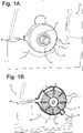
- FIG. 1A is a perspective view of a compressor 10 connected to an engine block 12 and crankshaft 13;
- FIG. 1B is a cross-sectional view of the compressor 10;
- FIG. 1C is a cross-sectional view through the compressor 10 and a portion of the engine block 12 and crankshaft 13.
- Crankshaft 13 includes end 14, which extends out of engine block 12.
- Engine block 12 is part of an engine, for example, for a vehicle.
- Crankshaft 13 rotates around axis A.
- Compressor 10 can be an air compressor for auxiliary systems, such as a low profile vane compressor or another type of air compressor.
- Compressor 10 includes housing 15 and rotor 16. Also shown are inlet 18, outlet 20, and seals 22a, 22b, 22c.
- Inlet 18 and/or outlet 20 can be part of compressor 10 housing 15 or can be separate parts, simply connecting to compressor housing 15.
- Inlet 18 and/or outlet 20 can be formed as pictured, though in addition or in alternative to what is shown, could have hoses, seals and/or other components necessary to make the sealing connections for air intake and output to various systems.
- Seals 22a, 22b, 22c can be shaft seals, lip seals or other types of seals which can ensure sealing between the compressor 10 and crankshaft 13. More or fewer seals could be included, and/or seal placement could be varied depending on the specific engine and compressor configuration.
- Housing 15 is connected to an outside of the engine block 12, for example by bolts, screws or other means.
- Inlet 18 is where air enters compressor 10, flowing into the housing 15, where it is driven by rotor 16 with vanes 17. The air is compressed and exits compressor housing 15 through outlet 20 where it can be taken to other engine systems which require compressed air.
- compressor housing 15 would be plastic or aluminium (including alloys and composites) though could be other types of materials.
- Rotor 16 and vanes 17 could be formed of a metallic material such as steel or brass, or could be formed of a plastic or other materials which can be directly and securely connected to crankshaft 13.
- Rotor 16 of compressor 10 connects directly to and coaxially with crankshaft 13.
- This connection is shown adjacent to engine block 12, and typically at or near end 14 of crankshaft, though in some embodiments this could be a distance from end 14 and not directly adjacent to engine block 12.
- This connection is formed such that the rotation of crankshaft 13 rotates rotor 16, driving vanes 17 of compressor 10.
- the connection can be through a splined connection, shrink fit, friction gasket, press-fit, friction washer and/or any other connection(s) or component(s) which securely connects rotor 16 to crankshaft 13 such that rotor 16 will rotate with the rotation of crankshaft 13 with little to no slippage. This will ensure that the compressor 10 rotor 16 is driven at the desired RPM for properly compressing air in compressor 10 for use in other engine systems.
- compressor 10 By securing compressor 10 housing 15 to an outside of the engine block 12 such that compressor 10 is aligned coaxially with crankshaft 13 and rotor 16 is directly connected to crankshaft 16, compressor 10 is able to be directly driven by crankshaft 13. This frees up more space in the overall engine package, allowing for more flexibility in other systems and the vehicle engine as a whole. As mentioned in the background, past systems used compressors which were typically driven by the auxiliary belt or another belt which looped through the engine and connected to the crankshaft. By directly and coaxially connecting the compressor 10 to the crankshaft, more engine space is freed-up.
- Such a configuration frees up space which could be used to add other desirable systems to the engine and/or reduce the size of the overall engine thereby improving the efficiency of the vehicle.
- Such a configuration is especially useful in electrified engines where system components are generally larger and some components which necessitated belts (e.g., alternators) are no longer used.
- Compressor 10 can provide the required compressed air for such a system, and the compressor 10 could be mounted directly where the cam belt would have been on the crankshaft (since the cam and cam belt are no longer needed in the camless engine). This could also be very useful in electrified engines which do not have an accessory belt and require compressed air and/or when there is no space left on a belt drive.
- the compressor 10 is able to be directly integrated into the engine, mounting the rotor 16 to the crankshaft 13 for driving the compressor 10, eliminating the need for a beltdrive or an electric compressor and resulting in an overall savings of space.
- FIG. 2A is a perspective view of a compressor 10' integrated into the engine block 12, and FIG. 2B is a view of compressor 10' with the lid 24 removed. Similar numbers are used for similar components, and only the differences will be discussed.
- compressor 10' housing 15' is formed integrally into engine block 12 such that the compressor housing is not a separate part.
- Compressor 10' includes a lid 24 for access to an inside of compressor 10'. This lid 24 is connected by connection members (e.g., screws, bolts, pins) through connection flanges 26, though could be secured in other manners, for example, snap fit, etc.
- Inlet 18 and/or outlet 20 can be formed integrally as shown in Figs. 2A-2B , or can be separate parts, for example, hoses connecting to compressor 10' to carry air into and out of compressor 10'.
- Compressor 10' connects rotor 16 directly to and coaxially to crankshaft 13 such that the rotation of crankshaft 13 rotates rotor 16, as in compressor 10 shown in Figs. 1A-1C .
- Forming compressor 10' housing integral to engine block 12 can result in even more space savings in the overall engine as well as assembly time savings in not having to separately connect the compressor housing to the engine block.
- a lid can simply be connected for access to the interior, for example, for easy inspection and maintenance purposes.
- the compressor 10, 10' rotor 16 is able to be driven directly by the crankshaft 13 without the need for additional belts or other secondary (or more) drive systems and components.
- Mounting the rotor 16 of compressor 10 coaxially and directly to crankshaft 13 saves package space, reduces complexity and dependencies, and removes the need for a separate electric compressor to run systems requiring compressed air.
- This makes for an overall reliable, compact and efficient engine configuration, allowing more engine flexibility for including systems which require compressed air while maintaining similar or reduced overall engine package size. Overall, such a configuration saves space in the engine bay, and results in fewer parts, reduced system dependencies, reduced complexity and less maintenance needs.
Landscapes
- Engineering & Computer Science (AREA)
- Mechanical Engineering (AREA)
- General Engineering & Computer Science (AREA)
- Chemical & Material Sciences (AREA)
- Combustion & Propulsion (AREA)
- Applications Or Details Of Rotary Compressors (AREA)
- Compressors, Vaccum Pumps And Other Relevant Systems (AREA)
Abstract
Description
- The current is related to engines, and in particular engines with a compressor.
- Modern engines are a collection of complex and dependent subsystems which must fit in a compact space. Electrical and hybrid engine systems and components often take up more space than those of internal combustion engines alone.
- Some engine systems require compressed air, which is typically delivered by an air compressor driven by a belt. This can be the auxiliary or cam belt, which wraps around the crankshaft and then loops over to drive the vane holder of the air compressor.
- According to a first aspect of the invention, a system comprises an engine block with a crankshaft able to rotate around axis A, and a compressor with a rotor, the rotor coaxially mounted to the crankshaft such that the crankshaft drives the rotor. Such a system results in a compact package with the crankshaft able to directly drive the compressor rotor, eliminating the need for separate components (e.g., belts) and extra space to accommodate the extra components and drive the compressor. Overall this configuration saves package space, reduces complexity and dependencies while providing a reliable and efficient system for a compressor to be installed on an engine.
- According to an embodiment, the crankshaft has a first end, and the rotor is mounted at or near the first end. In other embodiments, the rotor can be mounted a distance from the end. Optionally, the rotor is mounted adjacent to the engine block. By mounting the rotor directly to the crankshaft, the overall engine package with the compressor can be more compact and require fewer parts.
- According to an embodiment, the compressor comprises a housing, an inlet and an outlet. Optionally, the housing is mounted to the engine block. Further optionally, the housing is mounted to the engine block with bolts. Such a configuration can allow for simple manufacture of the compressor and housing, with simple and secure connections to the engine block such that the rotor can be mounted to the crankshaft.
- According to an embodiment, the housing is integral with the engine block. This means that part or all of the housing is formed with the engine block such that it is not able to be removed. This can be, for example, through casting, moulding and/or machining. Such a configuration is simple, having fewer parts, and can save assembly time and costs as the housing does not need to be separately produced and then secured to the engine block. Optionally, the housing comprises a lid. This can allow for easy access to the inner parts of a compressor housing even when formed integrally with the engine block.
- According to an embodiment, the rotor is mounted to the crankshaft via one or more of the following: shrink fit, splined connection, friction gasket, press-fit, and friction washer. Such connections and/or components help to ensure a secure connection between the crankshaft and compressor rotor such that the rotation of the crankshaft rotates the rotor, thereby driving the compressor. These connections can also help to ensure there is little to no slippage so that the rotor is driven at the desired revolutions per minute ("RPM") with the crankshaft.
- According to an embodiment, the compressor is an air compressor. Such a mechanically driven air compressor is useful for supplying compressed air to auxiliary systems on an engine, and can generally provide more power while taking up less space than prior art alternatives, such as belt-driven mechanical air compressors and electric air compressors.
- According to an embodiment, the system further comprises one or more seals. Such seals can be shaft seals, lip seals or any types of seals which provide sealing around the compressor and the engine such that fluid from the compressor does not leak into the surroundings and oil from the engine block does not leak out.
- According to a further aspect of the invention, a method comprises obtaining an engine block with a crankshaft; and mounting a rotor of a compressor to the crankshaft coaxially with the crankshaft such that crankshaft rotation directly drives the rotor. Such a method provides a compact and reliable way of delivering compressed air to sub systems of an engine from a compressor while minimizing the number of parts, complexity and space needed for driving the compressor.
- According to an embodiment, the method further comprises mounting a housing of the compressor to the engine block. This can be with bolts, screws, welding and/or any other means of securely mounting the housing. By mounting the housing to the engine block, the rotor can be mounted securely to the crankshaft such that no additional belt or other component is needed for driving the compressor. Additionally, the air being compressed does not need to travel as far when mounted directly to the engine block. Alternatively, the compressor housing could be formed integral with the engine block, minimizing separate parts even further and reducing assembly time.
- According to an embodiment, the method further comprises arranging one or more seals between the compressor and the crankshaft. Such seals can be shaft seals, lip seals or other types of seals which can ensure sealing between the compressor, shaft and engine block and thereby reduce the chances of fluid leakage from the compressor and/or the engine.
- According to an embodiment, the step of mounting a compressor with a rotor to the crankshaft comprises mounting via one or more of the following: shrink fit, splined connection, friction gasket, press-fit, and friction washer. Such mounting options can ensure a secure and reliable connections such that the rotation of the crankshaft rotates the rotor without slippage, thereby driving the rotor and compressor at the desired RPM.
- The details of one or more examples are set forth in the accompanying drawings and the description below. Other features, objects, and advantages of the disclosure will be apparent from the description and drawings, and from the claims.
-
-
FIG. 1A is a perspective view of a compressor connected to an engine block and crankshaft; -
FIG. 1B is a cross-sectional view of the compressor; -
FIG. 1C is a cross-sectional view through the compressor and a portion of the engine block and crank shaft; -
FIG. 2A is a perspective view of a compressor integrated into the engine block; and -
FIG. 2B is a view of the compressor ofFig. 2A with a lid removed. -
FIG. 1A is a perspective view of acompressor 10 connected to anengine block 12 andcrankshaft 13;FIG. 1B is a cross-sectional view of thecompressor 10; andFIG. 1C is a cross-sectional view through thecompressor 10 and a portion of theengine block 12 andcrankshaft 13.Crankshaft 13 includesend 14, which extends out ofengine block 12.Engine block 12 is part of an engine, for example, for a vehicle.Crankshaft 13 rotates around axis A. -
Compressor 10 can be an air compressor for auxiliary systems, such as a low profile vane compressor or another type of air compressor.Compressor 10 includeshousing 15 androtor 16. Also shown areinlet 18,outlet 20, and seals 22a, 22b, 22c.Inlet 18 and/oroutlet 20 can be part ofcompressor 10housing 15 or can be separate parts, simply connecting tocompressor housing 15.Inlet 18 and/oroutlet 20 can be formed as pictured, though in addition or in alternative to what is shown, could have hoses, seals and/or other components necessary to make the sealing connections for air intake and output to various systems. -
Seals compressor 10 andcrankshaft 13. More or fewer seals could be included, and/or seal placement could be varied depending on the specific engine and compressor configuration. -
Housing 15 is connected to an outside of theengine block 12, for example by bolts, screws or other means.Inlet 18 is where air enterscompressor 10, flowing into thehousing 15, where it is driven byrotor 16 withvanes 17. The air is compressed and exitscompressor housing 15 throughoutlet 20 where it can be taken to other engine systems which require compressed air. - Typically the
compressor housing 15 would be plastic or aluminium (including alloys and composites) though could be other types of materials.Rotor 16 andvanes 17 could be formed of a metallic material such as steel or brass, or could be formed of a plastic or other materials which can be directly and securely connected tocrankshaft 13. -
Rotor 16 ofcompressor 10 connects directly to and coaxially withcrankshaft 13. This connection is shown adjacent toengine block 12, and typically at ornear end 14 of crankshaft, though in some embodiments this could be a distance fromend 14 and not directly adjacent toengine block 12. This connection is formed such that the rotation ofcrankshaft 13 rotatesrotor 16, drivingvanes 17 ofcompressor 10. The connection can be through a splined connection, shrink fit, friction gasket, press-fit, friction washer and/or any other connection(s) or component(s) which securely connectsrotor 16 to crankshaft 13 such thatrotor 16 will rotate with the rotation ofcrankshaft 13 with little to no slippage. This will ensure that thecompressor 10rotor 16 is driven at the desired RPM for properly compressing air incompressor 10 for use in other engine systems. - By securing
compressor 10housing 15 to an outside of theengine block 12 such thatcompressor 10 is aligned coaxially withcrankshaft 13 androtor 16 is directly connected tocrankshaft 16,compressor 10 is able to be directly driven bycrankshaft 13. This frees up more space in the overall engine package, allowing for more flexibility in other systems and the vehicle engine as a whole. As mentioned in the background, past systems used compressors which were typically driven by the auxiliary belt or another belt which looped through the engine and connected to the crankshaft. By directly and coaxially connecting thecompressor 10 to the crankshaft, more engine space is freed-up. - Such a configuration frees up space which could be used to add other desirable systems to the engine and/or reduce the size of the overall engine thereby improving the efficiency of the vehicle. Such a configuration is especially useful in electrified engines where system components are generally larger and some components which necessitated belts (e.g., alternators) are no longer used.
- This configuration can be especially useful in camless piston engines which require compressed air for pneumatic actuation instead of conventional cams.
Compressor 10 can provide the required compressed air for such a system, and thecompressor 10 could be mounted directly where the cam belt would have been on the crankshaft (since the cam and cam belt are no longer needed in the camless engine). This could also be very useful in electrified engines which do not have an accessory belt and require compressed air and/or when there is no space left on a belt drive. Thus, thecompressor 10 is able to be directly integrated into the engine, mounting therotor 16 to thecrankshaft 13 for driving thecompressor 10, eliminating the need for a beltdrive or an electric compressor and resulting in an overall savings of space. -
FIG. 2A is a perspective view of acompressor 10' integrated into theengine block 12, andFIG. 2B is a view ofcompressor 10' with thelid 24 removed. Similar numbers are used for similar components, and only the differences will be discussed. - In this embodiment,
compressor 10' housing 15' is formed integrally intoengine block 12 such that the compressor housing is not a separate part.Compressor 10' includes alid 24 for access to an inside ofcompressor 10'. Thislid 24 is connected by connection members (e.g., screws, bolts, pins) throughconnection flanges 26, though could be secured in other manners, for example, snap fit, etc.Inlet 18 and/oroutlet 20 can be formed integrally as shown inFigs. 2A-2B , or can be separate parts, for example, hoses connecting tocompressor 10' to carry air into and out ofcompressor 10'.Compressor 10'connects rotor 16 directly to and coaxially to crankshaft 13 such that the rotation ofcrankshaft 13 rotatesrotor 16, as incompressor 10 shown inFigs. 1A-1C . - Forming
compressor 10' housing integral toengine block 12 can result in even more space savings in the overall engine as well as assembly time savings in not having to separately connect the compressor housing to the engine block. A lid can simply be connected for access to the interior, for example, for easy inspection and maintenance purposes. - In summary, the
compressor rotor 16 is able to be driven directly by thecrankshaft 13 without the need for additional belts or other secondary (or more) drive systems and components. Mounting therotor 16 ofcompressor 10 coaxially and directly to crankshaft 13 saves package space, reduces complexity and dependencies, and removes the need for a separate electric compressor to run systems requiring compressed air. This makes for an overall reliable, compact and efficient engine configuration, allowing more engine flexibility for including systems which require compressed air while maintaining similar or reduced overall engine package size. Overall, such a configuration saves space in the engine bay, and results in fewer parts, reduced system dependencies, reduced complexity and less maintenance needs. - While the invention has been described with reference to exemplary embodiments, it will be understood by those skilled in the art that various changes may be made and equivalents may be substituted for elements thereof without departing from the scope of the invention. In addition, many modifications may be made to adapt a particular situation or material to the teachings of the invention without departing from the essential scope thereof. Therefore, it is intended that the invention not be limited to the particular or preferred embodiments disclosed, but that the invention will include all embodiments falling within the scope of the appended claims.
Claims (15)
- A system comprising:an engine block (12) and a crankshaft (13) able to rotate around axis A, anda compressor (10, 10') with a rotor (16) mounted coaxially to the crankshaft (13) such that the crankshaft (13) drives the rotor (16).
- The system of claim 1, wherein the crankshaft (13) has a first end (14), and the rotor (16) is mounted at or near the first end (14).
- The system of any of the preceding claims, wherein the compressor (10) is mounted adjacent to the engine block.
- The system of any of the preceding claims, wherein the compressor (10, 10') comprises a housing (15), an inlet (18) and an outlet (20).
- The system of claim 4, wherein the housing (15) is mounted to the engine block (12).
- The system of claim 5, wherein the housing (15) is mounted to the engine block (12) with bolts.
- The system of claim 4, wherein the housing (15') is integral with the engine block (12).
- The system of claim 7, wherein the housing (15') comprises a lid (24).
- The system of any of the preceding claims, wherein the rotor (16) is mounted to the crankshaft (13) via one or more of the following: shrink fit, splined connection, friction gasket, press-fit, and friction washer.
- The system of any of the preceding claims, wherein the compressor (10, 10') is a low profile vane compressor.
- The system of any of the preceding claims, and further comprising one or more seals (22a, 22b, 22c).
- A method comprising:obtaining an engine block (12) with a crankshaft (13);mounting a compressor (10, 10') with a rotor (16) to the crankshaft (13) coaxially with the crankshaft (13) such that crankshaft rotation directly drives the rotor (16).
- The method of claim 12, and further comprising mounting a housing (15) of the compressor (10) to the engine block.
- The method of any of claims 12-13, and further comprising arranging one or more seals (22a, 22b, 22c) between the compressor (10, 10') and the crankshaft (13).
- The method of any of claims 12-14, wherein the step of mounting a compressor (10, 10') with a rotor (16) to the crankshaft (13) comprises mounting via one or more of the following: shrink fit, splined connection, friction gasket, press-fit, and friction washer.
Priority Applications (3)
| Application Number | Priority Date | Filing Date | Title |
|---|---|---|---|
| EP21160823.7A EP4053386A1 (en) | 2021-03-04 | 2021-03-04 | Crankshaft mounted compressor |
| US17/679,404 US20220282728A1 (en) | 2021-03-04 | 2022-02-24 | Crankshaft mounted compressor |
| CN202210202688.6A CN115030897B (en) | 2021-03-04 | 2022-03-03 | Compressor mounted to crankshaft |
Applications Claiming Priority (1)
| Application Number | Priority Date | Filing Date | Title |
|---|---|---|---|
| EP21160823.7A EP4053386A1 (en) | 2021-03-04 | 2021-03-04 | Crankshaft mounted compressor |
Publications (1)
| Publication Number | Publication Date |
|---|---|
| EP4053386A1 true EP4053386A1 (en) | 2022-09-07 |
Family
ID=74859214
Family Applications (1)
| Application Number | Title | Priority Date | Filing Date |
|---|---|---|---|
| EP21160823.7A Ceased EP4053386A1 (en) | 2021-03-04 | 2021-03-04 | Crankshaft mounted compressor |
Country Status (3)
| Country | Link |
|---|---|
| US (1) | US20220282728A1 (en) |
| EP (1) | EP4053386A1 (en) |
| CN (1) | CN115030897B (en) |
Citations (5)
| Publication number | Priority date | Publication date | Assignee | Title |
|---|---|---|---|---|
| US4998525A (en) * | 1989-06-12 | 1991-03-12 | Eftink Aloysius J | Air supply system for an internal combustion engine |
| DE202005017735U1 (en) * | 2005-11-12 | 2007-04-12 | Dolmar Gmbh | Integrated root loader |
| US20110048387A1 (en) * | 2009-08-18 | 2011-03-03 | Honda Motor Co., Ltd. | Supercharger Lubricating Structure for Internal Combustion Engine |
| CN107816384A (en) * | 2017-10-11 | 2018-03-20 | 中国航发南方工业有限公司 | Aviation hybrid power system and its unmanned plane based on radial-piston motor |
| CN110966085A (en) * | 2019-12-13 | 2020-04-07 | 浙江派尼尔科技股份有限公司 | Hand-held type pressure boost micro engine |
Family Cites Families (4)
| Publication number | Priority date | Publication date | Assignee | Title |
|---|---|---|---|---|
| KR100395080B1 (en) * | 1995-09-19 | 2003-11-01 | 론 리차드스 엔진 테크놀로지스 피티와이 리미티드 | Rotary internal combustion engine |
| GB0313399D0 (en) * | 2003-06-11 | 2003-07-16 | Holset Engineering Co | Compressor with secondary boost air outlet passage |
| CN101109383A (en) * | 2006-07-17 | 2008-01-23 | 上海日立电器有限公司 | Rolling piston type air-conditioner compressor used for hybrid automobile |
| GB201313824D0 (en) * | 2013-08-01 | 2013-09-18 | Orbital Power Ltd | A Rotary Engine |
-
2021
- 2021-03-04 EP EP21160823.7A patent/EP4053386A1/en not_active Ceased
-
2022
- 2022-02-24 US US17/679,404 patent/US20220282728A1/en not_active Abandoned
- 2022-03-03 CN CN202210202688.6A patent/CN115030897B/en active Active
Patent Citations (5)
| Publication number | Priority date | Publication date | Assignee | Title |
|---|---|---|---|---|
| US4998525A (en) * | 1989-06-12 | 1991-03-12 | Eftink Aloysius J | Air supply system for an internal combustion engine |
| DE202005017735U1 (en) * | 2005-11-12 | 2007-04-12 | Dolmar Gmbh | Integrated root loader |
| US20110048387A1 (en) * | 2009-08-18 | 2011-03-03 | Honda Motor Co., Ltd. | Supercharger Lubricating Structure for Internal Combustion Engine |
| CN107816384A (en) * | 2017-10-11 | 2018-03-20 | 中国航发南方工业有限公司 | Aviation hybrid power system and its unmanned plane based on radial-piston motor |
| CN110966085A (en) * | 2019-12-13 | 2020-04-07 | 浙江派尼尔科技股份有限公司 | Hand-held type pressure boost micro engine |
Also Published As
| Publication number | Publication date |
|---|---|
| CN115030897A (en) | 2022-09-09 |
| CN115030897B (en) | 2024-04-12 |
| US20220282728A1 (en) | 2022-09-08 |
Similar Documents
| Publication | Publication Date | Title |
|---|---|---|
| US8013488B2 (en) | Integration of a starter/generator module in a gas turbine transmission housing | |
| US5638796A (en) | Electric supercharger | |
| CN1230610C (en) | Improved power plant with internal combustion engine | |
| CN105074160B (en) | Supercharger manufacturing method and supercharger | |
| US7182585B2 (en) | Electrically driven flow compressor | |
| US20030070879A1 (en) | Submerged electric fluid pump | |
| CN102042390B (en) | Flexible mounting system for powertrain mounted components | |
| CN107735556B (en) | turbocharger unit | |
| KR102751526B1 (en) | Electrically driven charger, assembling method thereof and manufacturing method of motor housing | |
| US20220282728A1 (en) | Crankshaft mounted compressor | |
| CN211343336U (en) | Electric oil pump | |
| US20220282661A1 (en) | Crankshaft mounted pump | |
| US20200041053A1 (en) | Housing assembly for a turbocharger and method for fixing multiple connections to a housing | |
| US6422195B1 (en) | Accessory drive assembly | |
| GB2357377A (en) | Cooling a combined pump and electric generator | |
| EP3128150B1 (en) | Electrically driven supercharger, and supercharging system | |
| EP2199610A1 (en) | Electric compressor for vehicle-mounted air conditioner | |
| CN215058143U (en) | Compressor for vehicle | |
| KR20060111382A (en) | Exhaust Gas Turbocharger for Internal Combustion Engines | |
| US12078078B2 (en) | Cylinder head with integrated turbocharger | |
| KR20200077597A (en) | supercharger | |
| US20190226483A1 (en) | Motor vehicle vacuum pump | |
| US11499473B2 (en) | Compressor for an intake section of an internal combustion engine of a motor vehicle, internal combustion engine for a motor vehicle, and motor vehicle | |
| JP2024096106A (en) | Assembly and electric compressor with non-radial clamping feature - Patents.com | |
| CN102308095B (en) | Automotive internal combustion engine with pump |
Legal Events
| Date | Code | Title | Description |
|---|---|---|---|
| PUAI | Public reference made under article 153(3) epc to a published international application that has entered the european phase |
Free format text: ORIGINAL CODE: 0009012 |
|
| STAA | Information on the status of an ep patent application or granted ep patent |
Free format text: STATUS: THE APPLICATION HAS BEEN PUBLISHED |
|
| AK | Designated contracting states |
Kind code of ref document: A1 Designated state(s): AL AT BE BG CH CY CZ DE DK EE ES FI FR GB GR HR HU IE IS IT LI LT LU LV MC MK MT NL NO PL PT RO RS SE SI SK SM TR |
|
| STAA | Information on the status of an ep patent application or granted ep patent |
Free format text: STATUS: REQUEST FOR EXAMINATION WAS MADE |
|
| STAA | Information on the status of an ep patent application or granted ep patent |
Free format text: STATUS: EXAMINATION IS IN PROGRESS |
|
| 17P | Request for examination filed |
Effective date: 20230306 |
|
| RBV | Designated contracting states (corrected) |
Designated state(s): AL AT BE BG CH CY CZ DE DK EE ES FI FR GB GR HR HU IE IS IT LI LT LU LV MC MK MT NL NO PL PT RO RS SE SI SK SM TR |
|
| 17Q | First examination report despatched |
Effective date: 20230324 |
|
| STAA | Information on the status of an ep patent application or granted ep patent |
Free format text: STATUS: THE APPLICATION HAS BEEN REFUSED |
|
| 18R | Application refused |
Effective date: 20241119 |