EP4053344B1 - Kopplungsvorrichtung für eine arbeitsmaschine - Google Patents
Kopplungsvorrichtung für eine arbeitsmaschine Download PDFInfo
- Publication number
- EP4053344B1 EP4053344B1 EP22156998.1A EP22156998A EP4053344B1 EP 4053344 B1 EP4053344 B1 EP 4053344B1 EP 22156998 A EP22156998 A EP 22156998A EP 4053344 B1 EP4053344 B1 EP 4053344B1
- Authority
- EP
- European Patent Office
- Prior art keywords
- coupling device
- coupler body
- axis
- actuators
- working
- Prior art date
- Legal status (The legal status is an assumption and is not a legal conclusion. Google has not performed a legal analysis and makes no representation as to the accuracy of the status listed.)
- Active
Links
Images


Classifications
-
- E—FIXED CONSTRUCTIONS
- E02—HYDRAULIC ENGINEERING; FOUNDATIONS; SOIL SHIFTING
- E02F—DREDGING; SOIL-SHIFTING
- E02F3/00—Dredgers; Soil-shifting machines
- E02F3/04—Dredgers; Soil-shifting machines mechanically-driven
- E02F3/28—Dredgers; Soil-shifting machines mechanically-driven with digging tools mounted on a dipper- or bucket-arm, i.e. there is either one arm or a pair of arms, e.g. dippers, buckets
- E02F3/36—Component parts
- E02F3/3604—Devices to connect tools to arms, booms or the like
- E02F3/3609—Devices to connect tools to arms, booms or the like of the quick acting type, e.g. controlled from the operator seat
- E02F3/3659—Devices to connect tools to arms, booms or the like of the quick acting type, e.g. controlled from the operator seat electrically-operated
-
- E—FIXED CONSTRUCTIONS
- E02—HYDRAULIC ENGINEERING; FOUNDATIONS; SOIL SHIFTING
- E02F—DREDGING; SOIL-SHIFTING
- E02F3/00—Dredgers; Soil-shifting machines
- E02F3/04—Dredgers; Soil-shifting machines mechanically-driven
- E02F3/28—Dredgers; Soil-shifting machines mechanically-driven with digging tools mounted on a dipper- or bucket-arm, i.e. there is either one arm or a pair of arms, e.g. dippers, buckets
- E02F3/36—Component parts
- E02F3/3604—Devices to connect tools to arms, booms or the like
- E02F3/3609—Devices to connect tools to arms, booms or the like of the quick acting type, e.g. controlled from the operator seat
- E02F3/3618—Devices to connect tools to arms, booms or the like of the quick acting type, e.g. controlled from the operator seat with two separating hooks
-
- E—FIXED CONSTRUCTIONS
- E02—HYDRAULIC ENGINEERING; FOUNDATIONS; SOIL SHIFTING
- E02F—DREDGING; SOIL-SHIFTING
- E02F3/00—Dredgers; Soil-shifting machines
- E02F3/04—Dredgers; Soil-shifting machines mechanically-driven
- E02F3/28—Dredgers; Soil-shifting machines mechanically-driven with digging tools mounted on a dipper- or bucket-arm, i.e. there is either one arm or a pair of arms, e.g. dippers, buckets
- E02F3/36—Component parts
- E02F3/3604—Devices to connect tools to arms, booms or the like
- E02F3/3609—Devices to connect tools to arms, booms or the like of the quick acting type, e.g. controlled from the operator seat
- E02F3/3663—Devices to connect tools to arms, booms or the like of the quick acting type, e.g. controlled from the operator seat hydraulically-operated
-
- E—FIXED CONSTRUCTIONS
- E02—HYDRAULIC ENGINEERING; FOUNDATIONS; SOIL SHIFTING
- E02F—DREDGING; SOIL-SHIFTING
- E02F3/00—Dredgers; Soil-shifting machines
- E02F3/04—Dredgers; Soil-shifting machines mechanically-driven
- E02F3/28—Dredgers; Soil-shifting machines mechanically-driven with digging tools mounted on a dipper- or bucket-arm, i.e. there is either one arm or a pair of arms, e.g. dippers, buckets
- E02F3/36—Component parts
- E02F3/3604—Devices to connect tools to arms, booms or the like
- E02F3/3677—Devices to connect tools to arms, booms or the like allowing movement, e.g. rotation or translation, of the tool around or along another axis as the movement implied by the boom or arms, e.g. for tilting buckets
- E02F3/3681—Rotators
-
- E—FIXED CONSTRUCTIONS
- E02—HYDRAULIC ENGINEERING; FOUNDATIONS; SOIL SHIFTING
- E02F—DREDGING; SOIL-SHIFTING
- E02F3/00—Dredgers; Soil-shifting machines
- E02F3/04—Dredgers; Soil-shifting machines mechanically-driven
- E02F3/28—Dredgers; Soil-shifting machines mechanically-driven with digging tools mounted on a dipper- or bucket-arm, i.e. there is either one arm or a pair of arms, e.g. dippers, buckets
- E02F3/36—Component parts
- E02F3/3604—Devices to connect tools to arms, booms or the like
- E02F3/3686—Devices to connect tools to arms, booms or the like using adapters, i.e. additional element to mount between the coupler and the tool
Definitions
- the present teachings relate to a coupling device and to a working machine comprising a coupling device attached thereto.
- Working machines also known as off-highway vehicles, typically have a working arm pivotally mounted to the body of the machine, and a working implement, such as a bucket or a grabber, attached to the end of the arm via a coupling device. Attachment of the working implement enables the working machine to perform working operations.
- the coupling device may be capable of tilting the working implement relative to the working arm and also of rotating the working implement relative to the working arm.
- Such coupling devices are known as tiltrotators.
- the tiltrotator typically includes two actuators (e.g. hydraulic actuators).
- the packing of the different components may be such that operation of the tiltrotator in narrow spaces is difficult.
- WO2018083083 and KR101988828 describe tilt rotators with side mounted actuators.
- the present teachings seek to overcome or at least mitigate one or more problems associated with the prior art.
- a first aspect of the teachings provides for a coupling device for connecting a working implement to a working arm of a working machine, the coupling device comprising: a first coupler body comprising an arm mounting arrangement configured to be connectable to a working arm of a working machine; a second coupler body pivotally mounted to the first coupler body so as to be capable of tilting about a first axis; a third coupler body rotatably mounted to the second coupler body so as to be rotatable about a second axis, where the second axis is arranged at an angle to the first axis, the third coupler body comprising an implement mounting arrangement configured to be connectable to a working implement; and first and second spaced apart actuators configured to tilt the second coupler body relative to the first coupler body about the first axis, wherein the coupling device comprises a first end and a second end, and wherein the first and second actuators are arranged on the first end.
- Arranging the first and second actuators at the same end of the coupling device enables the footprint of the coupling device to be narrower, which has been found to facilitate operation of a working implement attached to the coupling device.
- the coupling device may be mounted to a working arm of a working machine, the first end is arranged distal to the working arm and the second end is arranged proximate to the working arm.
- Arranging the actuators on an opposing side of the coupling device to the arm further enables the footprint of the coupling device to be narrower.
- the first and second actuators may be arranged side-by-side.
- the first and second actuators may be arranged adjacent to each other.
- This arrangement further enables the footprint of the coupling device to be narrower.
- the second coupling body may define a width in a direction perpendicular to an axis extending between the first and second ends.
- the first and second actuators may be arranged to be narrower than the width of the second coupling body.
- the first and second actuators may define a width that is less than the width of the second coupling body.
- the widest part of the coupling device is the second coupling body, which has been found to further improve the packing of the coupling device, enabling a narrower coupling device to be provided.
- the arm mounting arrangement may comprise first and second arm mounts configured to receive first and second pivot pins, respectively, to pivotally mount the coupling device to a working arm of a working machine.
- the first arm mount may comprise a first pair of spaced apart apertures configured to receive a first pivot pin therethrough to pivotally mount the coupling device to a working arm of a working machine.
- the first arm mount may be provided on the second end of the coupling device.
- the first arm mount is provided on an opposing side of the coupling device to the first and second actuators.
- This arrangement has been found to further improve the packing of the coupling device, enabling a narrower coupling device to be provided.
- the second arm mount may comprise a second pair of spaced apart apertures configured to receive a second pivot pin therethrough for connecting the coupling device to an actuator of a working machine.
- the spaced apart apertures may define an axis extending therebetween that intersects the second axis.
- This arrangement has been found to improve the manoeuvrability/operability of an implement mounted to the coupling device.
- the first and second actuators may be pivotally connected to the second coupler body at first and second connection points, respectively, and the first and second connection points may be equally spaced apart from the first axis.
- the first and second connection points and the first axis may be arranged so as to define a substantially equilateral triangle.
- the first coupler body may comprise first and second actuator mounts configured to fixedly mount the first and second actuators thereto, respectively.
- the first and second actuator mounts may comprise first and second recesses, respectively, each recess defining an opening through which the first and second actuators at least partially extend.
- the first and second actuator mounts may comprise at least one aperture through the first coupler body so as to define at least one opening through which the first and second actuators at least partially extend.
- the first and second actuators may be pivotally connected to the second coupler body at first and second connection points, respectively.
- the second coupler body may comprise a projection defining third and fourth recesses on opposing sides thereof defining the first and second connection points.
- the first coupler body and second coupler body may each comprise complementary abutting surfaces configured and arranged to limit pivoting of the second coupler body relative to the first coupler body in first and second pivoting directions.
- the coupling device may comprise a hydraulic motor mounted to the second coupler body.
- the hydraulic motor may be positioned on the second end of the coupling device.
- the first coupler body and second coupler body may be pivotally connected by two spaced apart tilt pins extending along the first axis.
- a hydraulic manifold may be interposed between the first and second tilt pins.
- the third coupler body may be rotatably mounted to the second coupler body via a slewing arrangement.
- the slewing arrangement may comprise a worm gear.
- the third coupler body may be a quick coupler, e.g. a hydraulic quick coupler.
- the implement mounting arrangement may comprise first and second recesses configured to receive first and second implement pins therein.
- the first and second actuators may be arranged so as to be substantially parallel.
- the coupling device may be a tiltrotator.
- a second aspect of the teachings provides for a working machine comprising: a body; a ground engaging propulsion structure supporting the body; and a working arm mounted to the body, wherein a coupling device according to any preceding claim is mounted to a distal end of the working arm.
- the body may comprise an undercarriage supported by the ground engaging propulsion structure and a superstructure, e.g. a rotatable superstructure, connected to the undercarriage.
- a superstructure e.g. a rotatable superstructure
- the working arm may be mounted to the superstructure.
- the working machine may comprise an operator cab, wherein an operator seat is positioned within said operator cab.
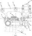
- a coupling device is illustrated and is indicated generally at 10.
- the coupling device 10 is connectable to a working arm of a working machine (not shown) so as to connect a working implement (not shown) to the working machine.
- the coupling device 10 is configured to tilt and rotate a working implement attached thereto. Put another way, the coupling device 10 is a tiltrotator 10.
- the coupling device 10 includes a first coupler body 12.
- the first coupler body 12 is integrally formed, e.g. integrally cast, as a unitary component. It will be appreciated that in alternative arrangements, the first coupler body 12 may be fabricated, forged, or may be formed from any suitable manufacturing method.
- the first coupler body 12 is pivotally connectable to a working arm so as to be pivotable about a pivot axis X.
- the pivot axis X is a lateral axis or horizontal axis. Put another way, the pivot axis X is a substantially transverse axis of the working machine to which the coupling device 10 is mounted. When the coupling device 10 is connected to a working machine, the pivot axis X is substantially parallel to a rotational axis between the working arm and the body of the working machine.
- the coupling device 10 includes a second coupler body 14.
- the second coupler body 14 is integrally formed, e.g. integrally cast, as a unitary component. It will be appreciated that in alternative arrangements, the second coupler body 14 may be fabricated, forged, or may be formed from any suitable manufacturing method.
- the second coupler body 14 is pivotally mounted to the first coupler body 12.
- the second coupler body 14 is pivotable relative to first coupler body 12 about a first axis Y. Pivotally mounting the second coupler body 14 to the first coupler body 12 enables the second coupler body 14 to tilt about the first axis Y. Put another way, the first axis Y is a tilt axis.
- the first axis Y is arranged at an angle (i.e. a non-zero angle) relative to the pivot axis X.
- the first axis Y is substantially perpendicular to the pivot axis X.
- the first axis Y is a substantially fore-aft axis.
- the first coupler body 12 and the second coupler body 14 are pivotally connected by two spaced apart tilt pins 16 extending along the first axis Y.
- the coupling device 10 includes a third coupler body 18.
- the third coupler body 18 is rotationally mounted to the second coupler body 14.
- the third coupler body 18 is rotatable relative to second coupling body 14 about a second axis Z.
- the second axis Z is arranged at an angle (i.e. a non-zero angle) relative to the first axis Y and to the pivot axis X.
- the second axis Z is arranged substantially perpendicular to the first axis Y and substantially perpendicular to the pivot axis X.
- the second axis Z is a substantially upright axis. Put another way, the second axis Z is a vertical axis.
- the third coupler body 18 is rotatably mounted to the second coupler body 14 via a slewing arrangement.
- the slewing arrangement comprises a worm gear (not shown).
- the coupling device 10 includes a device drive arrangement 20 configured to rotate the third coupler body 18 relative to the second coupler body 14. Put another way, the device drive arrangement 20 drives the slewing arrangement.
- the device drive arrangement 20 is interposed between the first and second tilt pins 16.
- the device drive arrangement 20 is provided in the form of a hydraulic motor 20 configured to drive the slewing arrangement.
- the hydraulic motor 20 is mounted to the second coupler body 14.
- the first and second actuators 24 are positioned on an opposing side of the second coupler body 14 to the hydraulic motor 20. Put another way, the first and second actuators 24 are positioned at the first end of the coupling device 10 and the drive arrangement 20 is positioned at the second end of the coupling device 10.
- the coupling device 10 includes a hydraulic manifold 26.
- the hydraulic manifold 26 directs the flow of hydraulic fluid within the coupling device 10.
- the hydraulic manifold 26 selectively provides hydraulic fluid to the drive arrangement 20 to drive the slewing arrangement. Put another way, the hydraulic manifold 26 selectively provides hydraulic fluid to the drive arrangement 20 to rotate the third coupler body 18 relative to the second coupler body 14.
- the third coupler body 18 includes an implement mounting arrangement 22 configured to be connectable to a working implement (not shown).
- the third coupler body 18 is a quick coupler.
- the mounting arrangement 22 includes first and second recesses configured to receive first and second implement pins of a working implement (not shown) therein.
- the coupling device 10 includes first and second spaced apart actuators 24 configured to tilt the second coupler body 14 relative to the first coupler body 12 about the first axis Y.
- the coupling device 10 includes a first end and a second end, and the first and second actuators 24 are arranged on the first end.
- the first end is arranged distal to the working arm and the second end is arranged proximate to the working arm.
- the first end is a front end of the coupling device 10.
- the first and second actuators 24 are arranged side-by-side on the coupling device 10. Put another way, the first and second actuators 24 are arranged adjacent to each other on the coupling device 10.
- the second coupler body 14 defines a width in a direction perpendicular to an axis extending between the first and second ends.
- the first and second actuators 24 are arranged to be narrower than the width of the second coupling body 14.
- the first and second actuators 24 are arranged so as to be substantially parallel to each other. Put another way, each of the first and second actuators 24 define an elongate axis, and the two elongate axes are substantially parallel. In alternative arrangements, the first and second actuators 24 may be arranged at an angle relative to each other.
- the first and second actuators 24 are arranged so as to be equally spaced apart from a central axis of the coupling device 10. In the embodiment, the first and second actuators 24 are arranged on a side of the coupling device 10 that is remote from the working arm, in use. The first and second actuators 24 are pivotally connected to the second coupler body 14 at first 28 and second 30 connection points, respectively. The first and second connection points 28, 30 are equally spaced apart from the first axis Y. In the embodiment, the first and second connection points 28, 30 and the first axis Y are arranged so as to define a substantially equilateral triangle.
- the second coupler body 14 includes a projection 34 defining third 36 and fourth 38 recesses on opposing sides thereof.
- the projection 34 is positioned on a side of coupling device 10 remote from a working arm of a working machine, when the coupling device 10 is mounted to a working arm.
- the projection 34 extends in a direction away from a working arm of a working machine, when the coupling device 10 is mounted to a working arm.
- the recesses 36, 38 define the first and second connection points.
- the recesses 36, 38 each include a pair of opposing apertures configured to receive a pin 40 therein so as to pivotally mount the first and second actuators 24 to the second coupler body 14.
- the pins 40 define the first and second connection points 28, 30.
- the first and second actuators 24 are fixedly mounted to the first coupler body 12.
- the first coupler body 12 includes first and second actuator mounts 32 to fixedly mount the first and second actuators 24 thereto.
- the first and second actuator mounts 32 are provided in the form of at least one aperture 42 through the first coupler body 12 so as to define at least one opening through which the first and second actuators 24 at least partially extend.
- the first coupler body 12 defines first and second apertures receiving the first and second actuators, respectively.
- the first and second actuator mounts 32 are positioned on a side of coupling device 10 remote from a working arm of a working machine, when the coupling device 10 is mounted to a working arm.
- the coupling device 10 is configured to limit the maximum angle that the first and second coupler bodies 12, 14 are able to tilt relative to each other.
- the first coupler body 12 and second coupler body 14 each comprise complementary abutting surfaces 44, 46 configured and arranged to limit tilting of the second coupler body 14 relative to the first coupler body 12 in first and second tilt directions.
- the first coupler body 12 includes an arm mounting arrangement 48 for pivotally mounting the first coupler body 12 to a working arm of a working machine.
- the arm mounting arrangement 48 includes first and second arm mounts.
- the first and second arm mounts are provided in the form of two pairs of opposing pivot pin holes configured to receive first and second pivot pins 50, 52, respectively, therethrough to mount the coupling device 10 to a working arm.
- the first pivot pin 50 pivotally mounts the coupling device 10 to the working arm.
- the first pivot pin 50 extends along the pivot axis X.
- the second pivot pin 52 mounts a linkage arm connected to an actuator (see Figure 6 ) configured to pivot the coupling device 10 about the pivot axis X.
- the coupling device 10 may not be pivotally mounted to the working arm, and the arm mounting arrangement 48 may fixedly mount the coupling device 10 to the working arm.
- the first pivot pin 50 is received in the pair of spaced apart apertures of the first arm mount.
- the first pivot pin 50 i.e. the first arm mount
- the second pivot pin 52 is received in the pair of spaced apart apertures of the second arm mount.
- the spaced apart apertures of the second arm mount define an axis extending therebetween that intersects the second axis Z. Put another way, the second pivot pin 52 extends along an axis that intersects the second axis Z.
- the first and second actuators 124 are fixedly mounted to the first coupler body 112.
- the first coupler body 112 includes first and second actuator mounts 132 to fixedly mount the first and second actuators 124 thereto.
- the first and second actuator mounts 132 are provided in the form of first and second recesses 154, 156.
- Each of the first and second recesses 154, 156 define an opening through which the first and second actuators 124 at least partially extend.
- the first and second actuator recesses 154, 156 are positioned on a side of coupling device 110 remote from a working arm of a working machine, when the coupling device 110 is mounted to a working arm.
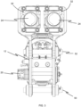
- the working machine 60 may be considered to be an excavator.
- the working machine 60 could be any type of working machine such as an excavator having any operating weight, a loader, a telehandler etc. Such working machines may be denoted as off-highway vehicles.
- the ground engaging propulsion structure includes a first, or front, axle A1 and a second, or rear, axle A2, each axle being coupled to a pair of wheels 62, 64.
- the ground engaging propulsion structure may include a pair of endless tracks.
- One or both of the axles A1, A2 may be coupled to a drive arrangement (not shown) configured to drive movement of the ground engaging propulsion structure (i.e. the axles A1, A2).
- the drive arrangement causes movement of the working machine 60 over a ground surface.
- the drive arrangement includes a primer mover and a transmission.
- the prime mover may be an internal combustion engine, an electric motor, or may be a hybrid comprising both an internal combustion engine, an electric motor.
- the working machine 60 has a body 66 supported on the ground engaging propulsion arrangement.
- the body 66 of the working machine 62 includes an undercarriage 68 supported on the ground engaging propulsion arrangement.
- a superstructure 70 is connected to the undercarriage 68.
- the superstructure 70 is connected to the undercarriage 68 by a mounting arrangement 72.
- the mounting arrangement 72 is a slewing mechanism in the form of a slewing ring.
- the mounting arrangement 72 permits unrestricted rotation of the superstructure 70 relative to the undercarriage 68 in this embodiment. In alternative arrangements it will be appreciated that the superstructure 70 may not be able to rotate relative to the undercarriage 68.
- a cab 74 from which an operator can operate the working machine 60 is mounted to the superstructure 70.
- the cab 74 includes an operator seat (not shown). It will be appreciated that in some arrangements, the working machine 60 may not include a cab 74 and the operator seat may be directly mounted on the body 66 of the working machine 60.
- the working machine 60 includes a working arm 76.
- the working arm 76 is connected to the body 66 and is provided for performing working operations.
- the working arm 76 is connected to the body 66.
- the working arm 76 is connected to the superstructure 70.
- the working machine 60 includes a counterweight 78 having a mass for counterbalancing the working arm 76.
- the counterweight 78 is provided on the superstructure 70. In alternative arrangements, it will be appreciated that the counterweight may be omitted.
- a coupling device 10, 110 is mounted to the working arm 76.
- the working arm 76 connects to the arm mounting arrangement 48, 148 of the coupling device 10, 110.
- the first pivot pin 50, 150 pivotally mounts the coupling device 10, 110 to the working arm 76.
- the second pivot pin 52, 152 mounts a linkage arm 80 connected to an actuator 82 configured to pivot the coupling device 10, 110 about the pivot axis X.
Landscapes
- Engineering & Computer Science (AREA)
- Mechanical Engineering (AREA)
- Mining & Mineral Resources (AREA)
- Civil Engineering (AREA)
- General Engineering & Computer Science (AREA)
- Structural Engineering (AREA)
- Agricultural Machines (AREA)
- Gear Transmission (AREA)
Claims (14)
- Kupplungsvorrichtung (10) zum Verbinden eines Arbeitsgeräts mit einem Arbeitsarm einer Arbeitsmaschine (60), die Kupplungsvorrichtung umfassend:einen ersten Kupplungskörper (12), der eine Armbefestigungsanordnung umfasst, die dazu beschaffen ist, mit einem Arbeitsarm einer Arbeitsmaschine verbunden zu werden,einen zweiten Kupplungskörper (14), der schwenkbar an dem ersten Kupplungskörper befestigt ist, so dass er um eine erste Achse gekippt werden kann, einen dritten Kupplungskörper (18), der drehbar an dem zweiten Kupplungskörper befestigt ist, so dass er um eine zweite Achse rotieren kann, wobei die zweite Achse in einem Winkel zur ersten Achse angeordnet ist, wobei der dritte Kupplungskörper eine Gerätebefestigungsanordnung (22) umfasst, die dazu beschaffen ist, mit einem Arbeitsgerät verbunden zu werden, underste und zweite voneinander beabstandete Aktuatoren (24), die dazu beschaffen sind, den zweiten Kupplungskörper relativ zu dem ersten Kupplungskörper um die erste Achse zu kippen,wobei die Kupplungsvorrichtung ein erstes Ende und ein zweites Ende umfasst und wobei die ersten und zweiten Aktuatoren an dem ersten Ende angeordnet sind, dadurch gekennzeichnet, dassdie ersten und zweiten Aktuatoren benachbart und nebeneinander am ersten Ende angeordnet sind.
- Kupplungsvorrichtung nach Anspruch 1, wobei, wenn die Kupplungsvorrichtung an einem Arbeitsarm einer Arbeitsmaschine befestigt ist, das erste Ende fern vom Arbeitsarm angeordnet ist und das zweite Ende nah am Arbeitsarm angeordnet ist.
- Kupplungsvorrichtung nach einem der vorhergehenden Ansprüche, wobei der zweite Kupplungskörper eine Breite in einer Richtung senkrecht zu einer Achse definiert, die zwischen dem ersten und dem zweiten Ende verläuft, und wobei die ersten und zweiten Aktuatoren so beschaffen sind, dass sie schmaler sind als die Breite des zweiten Kupplungskörpers.
- Kupplungsvorrichtung nach einem der vorhergehenden Ansprüche, wobei die Armbefestigungsanordnung erste und zweite Arm-Halterungen (32) umfasst, die dazu beschaffen sind, jeweils erste und zweite Schwenkbolzen (50, 52) aufnehmen, um die Kupplungsvorrichtung schwenkbar an einem Arbeitsarm einer Arbeitsmaschine zu befestigen, und wobei die erste Arm-Halterung am zweiten Ende der Kupplungsvorrichtung vorgesehen ist.
- Kupplungsvorrichtung nach einem der vorhergehenden Ansprüche, wobei die ersten und zweiten Aktuatoren jeweils an ersten und zweiten Verbindungspunkten schwenkbar mit dem zweiten Kupplungskörper verbunden sind und wobei die ersten und zweiten Verbindungspunkte gleich weit von der ersten Achse entfernt sind und wobei optional die ersten und zweiten Verbindungspunkte und die erste Achse so angeordnet sind, dass sie ein im Wesentlichen gleichseitiges Dreieck definieren.
- Kupplungsvorrichtung nach einem der vorhergehenden Ansprüche, wobei der erste Kupplungskörper erste und zweite Aktuator-Halterungen (132) umfasst, die dazu beschaffen sind, jeweils die ersten und zweiten Aktuatoren fest daran zu befestigen.
- Kupplungsvorrichtung nach Anspruch 6, wobei die erste und zweite Aktuator-Halterung jeweils eine erste und zweite Aussparung (154, 156) aufweisen, wobei jede Aussparung eine Öffnung definiert, durch die sich die ersten und zweiten Aktuatoren zumindest teilweise erstrecken.
- Kupplungsvorrichtung nach einem der vorhergehenden Ansprüche, wobei die ersten und zweiten Aktuatoren jeweils an ersten und zweiten Verbindungspunkten schwenkbar mit dem zweiten Kupplungskörper verbunden sind und wobei der zweite Kupplungskörper einen Vorsprung aufweist, der dritte und vierte Aussparungen auf gegenüberliegenden Seiten davon definiert, welche die ersten und zweiten Verbindungspunkte definieren.
- Kupplungsvorrichtung nach einem der vorhergehenden Ansprüche, wobei der erste Kupplungskörper und der zweite Kupplungskörper jeweils komplementäre Stoßflächen (44, 46) aufweisen, die dazu beschaffen und angeordnet sind, das Schwenken des zweiten Kupplungskörpers relativ zum ersten Kupplungskörper in die erste und zweite Schwenkrichtung zu begrenzen.
- Kupplungsvorrichtung nach einem der vorhergehenden Ansprüche, umfassend einen Hydraulikmotor, der an dem zweiten Kupplungskörper befestigt ist, wobei der Hydraulikmotor am zweiten Ende der Kupplungsvorrichtung angeordnet ist.
- Kupplungsvorrichtung nach einem der vorhergehenden Ansprüche, wobei der erste Kupplungskörper und der zweite Kupplungskörper durch zwei voneinander beabstandete, entlang der ersten Achse verlaufende Kippstifte (16) schwenkbar verbunden sind und wobei optional ein Hydraulikverteiler (26) zwischen den ersten und zweiten Kippstiften angeordnet ist.
- Kupplungsvorrichtung nach einem der vorhergehenden Ansprüche, wobei der dritte Kupplungskörper über eine Schwenkvorrichtung drehbar am zweiten Kupplungskörper befestigt ist und wobei optional die Schwenkvorrichtung ein Schneckengetriebe umfasst.
- Kupplungsvorrichtung nach einem der vorhergehenden Ansprüche, wobei der erste und der zweite Aktuator so angeordnet sind, dass sie im Wesentlichen parallel sind.
- Arbeitsmaschine (60), umfassend:einen Körper (66),eine mit dem Boden in Eingriff stehende Antriebsstruktur, welche den Körper trägt, undeinen am Körper befestigten Arbeitsarm (76),und eine Kupplungsvorrichtung nach einem der vorhergehenden Ansprüche 10, die an einem distalen Ende des Arbeitsarms befestigt ist.
Applications Claiming Priority (1)
| Application Number | Priority Date | Filing Date | Title |
|---|---|---|---|
| GB2102914.5A GB2604354B (en) | 2021-03-02 | 2021-03-02 | A Coupling Device |
Publications (3)
| Publication Number | Publication Date |
|---|---|
| EP4053344A1 EP4053344A1 (de) | 2022-09-07 |
| EP4053344C0 EP4053344C0 (de) | 2025-04-02 |
| EP4053344B1 true EP4053344B1 (de) | 2025-04-02 |
Family
ID=75377561
Family Applications (1)
| Application Number | Title | Priority Date | Filing Date |
|---|---|---|---|
| EP22156998.1A Active EP4053344B1 (de) | 2021-03-02 | 2022-02-16 | Kopplungsvorrichtung für eine arbeitsmaschine |
Country Status (3)
| Country | Link |
|---|---|
| US (1) | US12421687B2 (de) |
| EP (1) | EP4053344B1 (de) |
| GB (1) | GB2604354B (de) |
Family Cites Families (10)
| Publication number | Priority date | Publication date | Assignee | Title |
|---|---|---|---|---|
| JP2001020313A (ja) * | 1999-07-07 | 2001-01-23 | Konan Electric Co Ltd | 油圧ショベルのアタッチメント着脱装置 |
| SE537716C2 (sv) * | 2013-06-25 | 2015-10-06 | Steelwrist Ab | System, metod och datorprogram för att kontrollera rörelse på en entreprenadmaskins arbetsredskap |
| GB2549285B (en) * | 2016-04-11 | 2018-07-11 | Caterpillar Inc | An apparatus comprising a coupling arrangement |
| KR101783958B1 (ko) * | 2016-10-21 | 2017-10-10 | 주식회사 제이케이 | 회전형 퀵커플러 |
| SE541509C2 (en) * | 2016-11-04 | 2019-10-22 | Rototilt Group Ab | Method and hydraulic system for a tiltrotator with controlled diverter valve for auxiliary tool |
| WO2018192850A1 (en) * | 2017-04-19 | 2018-10-25 | Rototilt Group Ab | Control systems for an excavator and methods for controlling an excavator with a movable excavator thumb and an auxiliary tool hold by a tiltrotator |
| KR101988828B1 (ko) * | 2018-09-19 | 2019-06-12 | 김남학 | 굴삭기용 어태치먼트의 클램핑 장치 |
| SE1950075A1 (en) * | 2019-01-23 | 2020-07-24 | Rototilt Group Ab | A tool bracket and a tool implement comprising such a tool bracket |
| KR102215697B1 (ko) * | 2019-04-04 | 2021-02-15 | 정경래 | 굴착기용 분해조립형 틸트 로테이터 장치 |
| DE102020118938B3 (de) * | 2020-07-17 | 2021-07-29 | OilQuick Deutschland KG | Schnellwechselsystem zum Wechseln von Anbaugeräten an einer Baumaschine |
-
2021
- 2021-03-02 GB GB2102914.5A patent/GB2604354B/en active Active
-
2022
- 2022-02-16 EP EP22156998.1A patent/EP4053344B1/de active Active
- 2022-02-24 US US17/680,286 patent/US12421687B2/en active Active
Also Published As
| Publication number | Publication date |
|---|---|
| GB2604354A (en) | 2022-09-07 |
| GB202102914D0 (en) | 2021-04-14 |
| EP4053344A1 (de) | 2022-09-07 |
| US12421687B2 (en) | 2025-09-23 |
| GB2604354B (en) | 2023-12-06 |
| EP4053344C0 (de) | 2025-04-02 |
| US20220282446A1 (en) | 2022-09-08 |
Similar Documents
| Publication | Publication Date | Title |
|---|---|---|
| EP1947249B1 (de) | Gemeinsames Gelenk und Stützelement für eine Anhangschnittstelle eines Laders. | |
| CN115244249A (zh) | 电动动力机械 | |
| US10480154B2 (en) | Implement carrier and implements | |
| EP0863264B1 (de) | Schaufelbagger mit teleskopischem Arm | |
| US20140260149A1 (en) | Rotary Cutter Implement for Power Machine | |
| US7770370B2 (en) | Device for limiting lowering of implement on working vehicle | |
| KR102657223B1 (ko) | 작업 기계용 하부 주행체 | |
| KR20160052391A (ko) | 작업 기계용 하부 주행체 | |
| CN113348283A (zh) | 用于动力机械特别是迷你装载机的机械自调平提升臂结构 | |
| EP4053344B1 (de) | Kopplungsvorrichtung für eine arbeitsmaschine | |
| EP3851363B1 (de) | Achsanordnung | |
| AU2582597A (en) | Frame assembly for a construction machine | |
| EP4245925A1 (de) | Schnellkupplung | |
| EP3795753B1 (de) | Arbeitsmaschine | |
| CN110536985B (zh) | 用于装载机的机械驱动控制器 | |
| JPH11513087A (ja) | 関節式建設機械用フレームアセンブリ | |
| EP4534762A1 (de) | Drehrahmen und arbeitsmaschine |
Legal Events
| Date | Code | Title | Description |
|---|---|---|---|
| PUAI | Public reference made under article 153(3) epc to a published international application that has entered the european phase |
Free format text: ORIGINAL CODE: 0009012 |
|
| STAA | Information on the status of an ep patent application or granted ep patent |
Free format text: STATUS: THE APPLICATION HAS BEEN PUBLISHED |
|
| AK | Designated contracting states |
Kind code of ref document: A1 Designated state(s): AL AT BE BG CH CY CZ DE DK EE ES FI FR GB GR HR HU IE IS IT LI LT LU LV MC MK MT NL NO PL PT RO RS SE SI SK SM TR |
|
| RIN1 | Information on inventor provided before grant (corrected) |
Inventor name: SHENTON, JAMIE THOMAS LEWIS Inventor name: RATCLIFFE, SIMON Inventor name: COTTINGHAM, DARRYL |
|
| STAA | Information on the status of an ep patent application or granted ep patent |
Free format text: STATUS: REQUEST FOR EXAMINATION WAS MADE |
|
| STAA | Information on the status of an ep patent application or granted ep patent |
Free format text: STATUS: EXAMINATION IS IN PROGRESS |
|
| 17P | Request for examination filed |
Effective date: 20230302 |
|
| RBV | Designated contracting states (corrected) |
Designated state(s): AL AT BE BG CH CY CZ DE DK EE ES FI FR GB GR HR HU IE IS IT LI LT LU LV MC MK MT NL NO PL PT RO RS SE SI SK SM TR |
|
| 17Q | First examination report despatched |
Effective date: 20230329 |
|
| GRAP | Despatch of communication of intention to grant a patent |
Free format text: ORIGINAL CODE: EPIDOSNIGR1 |
|
| STAA | Information on the status of an ep patent application or granted ep patent |
Free format text: STATUS: GRANT OF PATENT IS INTENDED |
|
| RIC1 | Information provided on ipc code assigned before grant |
Ipc: E02F 3/36 20060101AFI20241108BHEP |
|
| INTG | Intention to grant announced |
Effective date: 20241203 |
|
| P01 | Opt-out of the competence of the unified patent court (upc) registered |
Free format text: CASE NUMBER: APP_53/2025 Effective date: 20250102 |
|
| GRAS | Grant fee paid |
Free format text: ORIGINAL CODE: EPIDOSNIGR3 |
|
| GRAA | (expected) grant |
Free format text: ORIGINAL CODE: 0009210 |
|
| STAA | Information on the status of an ep patent application or granted ep patent |
Free format text: STATUS: THE PATENT HAS BEEN GRANTED |
|
| AK | Designated contracting states |
Kind code of ref document: B1 Designated state(s): AL AT BE BG CH CY CZ DE DK EE ES FI FR GB GR HR HU IE IS IT LI LT LU LV MC MK MT NL NO PL PT RO RS SE SI SK SM TR |
|
| REG | Reference to a national code |
Ref country code: GB Ref legal event code: FG4D |
|
| REG | Reference to a national code |
Ref country code: CH Ref legal event code: EP |
|
| REG | Reference to a national code |
Ref country code: IE Ref legal event code: FG4D |
|
| REG | Reference to a national code |
Ref country code: DE Ref legal event code: R096 Ref document number: 602022012426 Country of ref document: DE |
|
| U01 | Request for unitary effect filed |
Effective date: 20250403 |
|
| P04 | Withdrawal of opt-out of the competence of the unified patent court (upc) registered |
Free format text: CASE NUMBER: APP_16921/2025 Effective date: 20250408 |
|
| U07 | Unitary effect registered |
Designated state(s): AT BE BG DE DK EE FI FR IT LT LU LV MT NL PT RO SE SI Effective date: 20250410 |
|
| PG25 | Lapsed in a contracting state [announced via postgrant information from national office to epo] |
Ref country code: ES Free format text: LAPSE BECAUSE OF FAILURE TO SUBMIT A TRANSLATION OF THE DESCRIPTION OR TO PAY THE FEE WITHIN THE PRESCRIBED TIME-LIMIT Effective date: 20250402 |
|
| PG25 | Lapsed in a contracting state [announced via postgrant information from national office to epo] |
Ref country code: GR Free format text: LAPSE BECAUSE OF FAILURE TO SUBMIT A TRANSLATION OF THE DESCRIPTION OR TO PAY THE FEE WITHIN THE PRESCRIBED TIME-LIMIT Effective date: 20250703 Ref country code: NO Free format text: LAPSE BECAUSE OF FAILURE TO SUBMIT A TRANSLATION OF THE DESCRIPTION OR TO PAY THE FEE WITHIN THE PRESCRIBED TIME-LIMIT Effective date: 20250702 |
|
| PG25 | Lapsed in a contracting state [announced via postgrant information from national office to epo] |
Ref country code: PL Free format text: LAPSE BECAUSE OF FAILURE TO SUBMIT A TRANSLATION OF THE DESCRIPTION OR TO PAY THE FEE WITHIN THE PRESCRIBED TIME-LIMIT Effective date: 20250402 |
|
| PG25 | Lapsed in a contracting state [announced via postgrant information from national office to epo] |
Ref country code: HR Free format text: LAPSE BECAUSE OF FAILURE TO SUBMIT A TRANSLATION OF THE DESCRIPTION OR TO PAY THE FEE WITHIN THE PRESCRIBED TIME-LIMIT Effective date: 20250402 |
|
| PG25 | Lapsed in a contracting state [announced via postgrant information from national office to epo] |
Ref country code: RS Free format text: LAPSE BECAUSE OF FAILURE TO SUBMIT A TRANSLATION OF THE DESCRIPTION OR TO PAY THE FEE WITHIN THE PRESCRIBED TIME-LIMIT Effective date: 20250702 |
|
| PG25 | Lapsed in a contracting state [announced via postgrant information from national office to epo] |
Ref country code: IS Free format text: LAPSE BECAUSE OF FAILURE TO SUBMIT A TRANSLATION OF THE DESCRIPTION OR TO PAY THE FEE WITHIN THE PRESCRIBED TIME-LIMIT Effective date: 20250802 |
|
| PG25 | Lapsed in a contracting state [announced via postgrant information from national office to epo] |
Ref country code: SM Free format text: LAPSE BECAUSE OF FAILURE TO SUBMIT A TRANSLATION OF THE DESCRIPTION OR TO PAY THE FEE WITHIN THE PRESCRIBED TIME-LIMIT Effective date: 20250402 |
|
| PG25 | Lapsed in a contracting state [announced via postgrant information from national office to epo] |
Ref country code: CZ Free format text: LAPSE BECAUSE OF FAILURE TO SUBMIT A TRANSLATION OF THE DESCRIPTION OR TO PAY THE FEE WITHIN THE PRESCRIBED TIME-LIMIT Effective date: 20250402 |
|
| PG25 | Lapsed in a contracting state [announced via postgrant information from national office to epo] |
Ref country code: SK Free format text: LAPSE BECAUSE OF FAILURE TO SUBMIT A TRANSLATION OF THE DESCRIPTION OR TO PAY THE FEE WITHIN THE PRESCRIBED TIME-LIMIT Effective date: 20250402 |
|
| PLBE | No opposition filed within time limit |
Free format text: ORIGINAL CODE: 0009261 |
|
| STAA | Information on the status of an ep patent application or granted ep patent |
Free format text: STATUS: NO OPPOSITION FILED WITHIN TIME LIMIT |
|
| REG | Reference to a national code |
Ref country code: CH Ref legal event code: L10 Free format text: ST27 STATUS EVENT CODE: U-0-0-L10-L00 (AS PROVIDED BY THE NATIONAL OFFICE) Effective date: 20260211 |
|
| 26N | No opposition filed |
Effective date: 20260105 |
|
| U20 | Renewal fee for the european patent with unitary effect paid |
Year of fee payment: 5 Effective date: 20260213 |