EP4053064B1 - Hoisting mechanism for large heavy-load component in nuclear fusion environment - Google Patents
Hoisting mechanism for large heavy-load component in nuclear fusion environment Download PDFInfo
- Publication number
- EP4053064B1 EP4053064B1 EP20883497.8A EP20883497A EP4053064B1 EP 4053064 B1 EP4053064 B1 EP 4053064B1 EP 20883497 A EP20883497 A EP 20883497A EP 4053064 B1 EP4053064 B1 EP 4053064B1
- Authority
- EP
- European Patent Office
- Prior art keywords
- arc
- base frame
- arms
- gear
- hoisting mechanism
- Prior art date
- Legal status (The legal status is an assumption and is not a legal conclusion. Google has not performed a legal analysis and makes no representation as to the accuracy of the status listed.)
- Active
Links
Images

Classifications
-
- B—PERFORMING OPERATIONS; TRANSPORTING
- B66—HOISTING; LIFTING; HAULING
- B66C—CRANES; LOAD-ENGAGING ELEMENTS OR DEVICES FOR CRANES, CAPSTANS, WINCHES, OR TACKLES
- B66C1/00—Load-engaging elements or devices attached to lifting or lowering gear of cranes or adapted for connection therewith for transmitting lifting forces to articles or groups of articles
- B66C1/10—Load-engaging elements or devices attached to lifting or lowering gear of cranes or adapted for connection therewith for transmitting lifting forces to articles or groups of articles by mechanical means
- B66C1/42—Gripping members engaging only the external or internal surfaces of the articles
- B66C1/425—Gripping members engaging only the external or internal surfaces of the articles motor actuated
-
- B—PERFORMING OPERATIONS; TRANSPORTING
- B66—HOISTING; LIFTING; HAULING
- B66C—CRANES; LOAD-ENGAGING ELEMENTS OR DEVICES FOR CRANES, CAPSTANS, WINCHES, OR TACKLES
- B66C13/00—Other constructional features or details
- B66C13/04—Auxiliary devices for controlling movements of suspended loads, or preventing cable slack
- B66C13/08—Auxiliary devices for controlling movements of suspended loads, or preventing cable slack for depositing loads in desired attitudes or positions
-
- G—PHYSICS
- G21—NUCLEAR PHYSICS; NUCLEAR ENGINEERING
- G21D—NUCLEAR POWER PLANT
- G21D1/00—Details of nuclear power plant
- G21D1/02—Arrangements of auxiliary equipment
-
- Y—GENERAL TAGGING OF NEW TECHNOLOGICAL DEVELOPMENTS; GENERAL TAGGING OF CROSS-SECTIONAL TECHNOLOGIES SPANNING OVER SEVERAL SECTIONS OF THE IPC; TECHNICAL SUBJECTS COVERED BY FORMER USPC CROSS-REFERENCE ART COLLECTIONS [XRACs] AND DIGESTS
- Y02—TECHNOLOGIES OR APPLICATIONS FOR MITIGATION OR ADAPTATION AGAINST CLIMATE CHANGE
- Y02E—REDUCTION OF GREENHOUSE GAS [GHG] EMISSIONS, RELATED TO ENERGY GENERATION, TRANSMISSION OR DISTRIBUTION
- Y02E30/00—Energy generation of nuclear origin
- Y02E30/10—Nuclear fusion reactors
-
- Y—GENERAL TAGGING OF NEW TECHNOLOGICAL DEVELOPMENTS; GENERAL TAGGING OF CROSS-SECTIONAL TECHNOLOGIES SPANNING OVER SEVERAL SECTIONS OF THE IPC; TECHNICAL SUBJECTS COVERED BY FORMER USPC CROSS-REFERENCE ART COLLECTIONS [XRACs] AND DIGESTS
- Y02—TECHNOLOGIES OR APPLICATIONS FOR MITIGATION OR ADAPTATION AGAINST CLIMATE CHANGE
- Y02E—REDUCTION OF GREENHOUSE GAS [GHG] EMISSIONS, RELATED TO ENERGY GENERATION, TRANSMISSION OR DISTRIBUTION
- Y02E30/00—Energy generation of nuclear origin
- Y02E30/30—Nuclear fission reactors
Definitions
- the invention relates to the technical field of nuclear fusion reactor engineering, in particular to a hoisting mechanism for large heavy-load component in nuclear fusion environment.
- DE 35 17 460 A1 discloses a hoisting mechanism comprising a gripper whose arms are guided by carriers along guide surfaces of a casing. Each carrier is provided with toothed racks between which a gear is arranged that is driven by an electric motor.
- the weight of a single divertor is as high as ten tons, and the transfer mechanism needs to enter the vacuum vessel through the dedicated port to take out the divertor, which puts forward higher space and load requirements for the transfer mechanism.
- the maintenance method of the divertor currently implemented is mainly a combination of manual and mechanical, which is difficult to adapt to the development needs of remote handling in the future fusion reactor nuclear fusion environment.
- the purpose of the present invention is to provide a hoisting mechanism for large heavy-load component in nuclear fusion environment, so as to solve the problem that the nuclear fusion reactor in the prior art requires manual transfer of the divertor.
- a hoisting mechanism for large heavy-load component in nuclear fusion environment comprising: a base frame, a pair of hanger arms, a top motor is provided at a front position in the base frame, wherein an output shaft of the top motor is connected with a first gear, wherein the pair of hanger arms are respectively arranged on left and right sides of the base frame and opposite to each other; at the front position in the base frame and on an upper portion of each of the hanger arms, first racks are respectively provided on front and rear sides of the first gear and opposite to each other; the first gear is engageable with the two opposing first racks at the same time; and a lower portion of each of the pair of hanger arms extends downward beyond a bottom of the base frame; a pair of arc arms (2) and rotary motors (8) are provided at a rear position in the base frame (1), the pair of arc arms are respectively arranged on the left and right sides of the base frame;
- each of the support points is a rotating wheel that is rotatably mounted on the base frame, and the rotating wheel is respectively located in the arc-shaped groove of the arc arm on the corresponding side to provide support to the arc arm.
- the output shaft of the top motor is connected with an input shaft of a 90-degree angle reducer, and the first gear is fixedly mounted on an output shaft of the 90-degree angle reducer.
- the arc arms are mounted on opposite sides of the base frame, the rotary motor drives the arc arm through the second gear and the second rack provided on the arc arm, so that the arc arm moves along the arc shape determined by the plurality of support points; and a lower portion of each of the arc arms is provided with a connecting member.
- the two hanger arms are arranged on the left and right sides, the top motor drives the two hanger arms to move oppositely at the same time to be close to or away from each other through gears and racks, and the hanger arm can enter and exit (extend and retract) along the direction of the catching groove.
- a lower portion of each of the hanger arms is provided with a protruding roller for connecting large heavy-load component.
- the power of the top motor 7 is transmitted to the first rack 5-1 via the first gear 11-1, and drives the first connecting member 5-2 to slide back and forth in the respective catching grooves 9, so that the two hanger arms 5 can move in opposite directions relative to each other.
- the two hanger arms 5 can move oppositely to be close to or away from each other along the left-right direction of the base frame 1, so as to realize the clamping and releasing of the divertor 13 by the roller 4 located at the lower end.
- the two arc arms 2 are arranged on the left and right sides of the base frame 1, and the outer arc surface of each of the arc arm 2 faces upward.
- Each of the arc arm 2 is respectively provided with an arc-shaped groove 2-2 corresponding to a shape of the arc arm, and the arc-shaped groove 2-2 penetrates through the arc arm 2 in the left-right direction respectively.
- a second rack 2-1 corresponding to the shape of the arc arm 2 is respectively provided on the outer arc surface of each of the arc arms 2, an arcuate length of the second rack 2-1 is smaller than an arcuate length of the outer arc surface of the arc arm 2.
- the left and right sides of the base frame 1 are also rotatably mounted with second gears 10 corresponding to the positions of the rotary motor 8, respectively, the second gears 10 are respectively drive-engaged with the second racks 2-1 on the outer arc surfaces of the arc arm 2 on the corresponding side, the output shafts of the two rotary motors 8 are respectively in a one-to-one correspondence with the two second gears 10 for transmission connection.
- the output shaft of the top motor 7 is connected with the input shaft of a 90-degree angle first reducer 11, and the first gear 11-1 is fixedly mounted on the output shaft of the 90-degree angle reducer 11.
- the first gear racks 5-1 on both sides are driven by the first gear 11-1 to drive the sliding of the first connecting member 5-2 and through the sliding of the first connecting member 5-2, the hanger arm 5 is extended and retracted through the second connecting member 5-3 (the two hanger arms 5 can move oppositely to be close to or away from each other along the left-right direction of the base frame 1).
- the divertor 13 is jointly held by the two hanger arms 5 and the two arc arms 2. As shown in FIG. 6 , when the divertor 13 needs to be rotated, the arc arm 2 is extended to realize the rotation of the divertor 13.
Landscapes
- Engineering & Computer Science (AREA)
- Mechanical Engineering (AREA)
- Carriers, Traveling Bodies, And Overhead Traveling Cranes (AREA)
- Types And Forms Of Lifts (AREA)
Description
- The invention relates to the technical field of nuclear fusion reactor engineering, in particular to a hoisting mechanism for large heavy-load component in nuclear fusion environment.
DE 35 17 460 A1 discloses a hoisting mechanism comprising a gripper whose arms are guided by carriers along guide surfaces of a casing. Each carrier is provided with toothed racks between which a gear is arranged that is driven by an electric motor. - Nuclear fusion energy is a relatively a new type of clean energy, which has the characteristics of less consumption of raw materials, abundant resources and less radioactive pollution. Therefore, the research of controlled nuclear fusion has been paid more and more attention by countries all over the world. Magnetic confinement fusion of tokamak is considered to be one of the most promising avenues in the commercialization of fusion energy research. Tokamaks contain a ring-shaped vacuum vessel where fusion reactions take place. During the operation of the device, since the divertor of the first wall component in the vacuum vessel has been operated in the nuclear radiation environment for a long time, it is subjected to plasma thermal shock and neutron irradiation at the same time, which will cause great damage after a period of operation. Therefore, it needs to be transferred outside the tokamak device for maintenance. The weight of a single divertor is as high as ten tons, and the transfer mechanism needs to enter the vacuum vessel through the dedicated port to take out the divertor, which puts forward higher space and load requirements for the transfer mechanism. In addition, in the nuclear fusion environment, there should be no medium such as hydraulic oil that can potentially contaminate the inside of the device. The maintenance method of the divertor currently implemented is mainly a combination of manual and mechanical, which is difficult to adapt to the development needs of remote handling in the future fusion reactor nuclear fusion environment.
- The purpose of the present invention is to provide a hoisting mechanism for large heavy-load component in nuclear fusion environment, so as to solve the problem that the nuclear fusion reactor in the prior art requires manual transfer of the divertor.
- In order to achieve the above object, the technical solution adopted in the present invention is as follows: a hoisting mechanism for large heavy-load component in nuclear fusion environment, the hoisting mechanism comprising: a base frame, a pair of hanger arms, a top motor is provided at a front position in the base frame, wherein an output shaft of the top motor is connected with a first gear, wherein the pair of hanger arms are respectively arranged on left and right sides of the base frame and opposite to each other; at the front position in the base frame and on an upper portion of each of the hanger arms, first racks are respectively provided on front and rear sides of the first gear and opposite to each other; the first gear is engageable with the two opposing first racks at the same time; and a lower portion of each of the pair of hanger arms extends downward beyond a bottom of the base frame; a pair of arc arms (2) and rotary motors (8) are provided at a rear position in the base frame (1), the pair of arc arms are respectively arranged on the left and right sides of the base frame; an outer arc surface of each of the arc arms faces upward, one end of the arc arm extends forward and upward, and the other end of the arc arm extends rearward and downward beyond the bottom of the base frame; each of the arc arms is respectively provided with an arc-shaped groove corresponding to a shape of the arc arm and penetrating through the arc arm in a left-right direction; a second rack corresponding to the shape of the arc arm is respectively provided on the outer arc surface of each of the arc arms; and a plurality of support points are respectively provided on the left and right sides of the base frame which are arranged in an arc shape matching the arc arm, and each of the arc arms is slidably fitted to the respective support points on the corresponding side through the respective arc-shaped groove, and wherein second gears are respectively mounted on the left and right sides of the base frame at positions corresponding to the rotary motors, the second gear is respectively drive-engaged with the second rack of the arc arm on the corresponding side, and an output shaft of the rotary motor is drive-connected with the second gear.
- Further, four corner positions of a top of the base frame are respectively connected with a hanging lug.
- Further, each of the support points is a rotating wheel that is rotatably mounted on the base frame, and the rotating wheel is respectively located in the arc-shaped groove of the arc arm on the corresponding side to provide support to the arc arm.
- Further, an arcuate length of the second rack is smaller than an arcuate length of the outer arc surface of the arc arm.
- Further, an inner surface of a lower end of each of the pair of hanger arms is respectively formed into a protruding surface, and a roller is respectively mounted rotatably on the protruding surface; and the roller is concentric with the arc arm on the corresponding side.
- Further, the output shaft of the top motor is connected with an input shaft of a 90-degree angle reducer, and the first gear is fixedly mounted on an output shaft of the 90-degree angle reducer.
- Further, the number of the rotary motors is two; and the output shaft of each of the rotary motors is respectively connected with an input shaft of a 90-degree angle reducer, and an output shaft of each of the 90-degree angle reducers is respectively connected coaxially with one of the second gears.
- Further, catching grooves extending along the left-right direction of the base frame are respectively provided on the front and rear sides of the first gear at the bottom of the base frame; a first connecting member is respectively provided on the upper portion of each of the hanger arms, each of the first racks is respectively fixed on the corresponding first connecting member, and the first connecting member is slidably caught in the corresponding catching groove; the top motor drives the first connecting members to slide back and forth in the respective catching grooves through the first gear and the first racks engaged with the first gear, so that the hanger arms move oppositely to be close to or away from each other along the left-right direction of the base frame; and a lower portion of each of the hanger arms is provided with a protruding roller.
- Further, the arc arms are mounted on opposite sides of the base frame, the rotary motor drives the arc arm through the second gear and the second rack provided on the arc arm, so that the arc arm moves along the arc shape determined by the plurality of support points; and a lower portion of each of the arc arms is provided with a connecting member.
- Further, an inner surface of a lower end of each of the pair of hanger arms is respectively formed into a protruding surface, and a roller is respectively mounted rotatably on the protruding surface; the roller and the arc arm on the corresponding side are located on a concentric circle; and when the hanger arms and the arc arms are both connected to a divertor component to be transported, the arc arms are driven to rotate the divertor component along an arc concentric with the rollers.
- Further, catching grooves extending along the left-right direction of the base frame are respectively provided on the front and rear sides of the first gear at the bottom of the base frame; a second connecting member fixedly connected with a first connecting member is respectively provided on the upper portion of each of the hanger arms, the first connecting member is slidably caught in the corresponding catching groove, and each of the first racks is respectively fixed on the corresponding first connecting member; the top motor drives the first connecting members to slide back and forth in the respective catching grooves through the first gear and the first racks engaged with the first gear, so that the two hanger arms move oppositely at the same time to be close to or away from each other along the left-right direction of the base frame; and a lower portion of each of the hanger arms is provided with a protruding roller.
- In the present invention, the two hanger arms are arranged on the left and right sides, the top motor drives the two hanger arms to move oppositely at the same time to be close to or away from each other through gears and racks, and the hanger arm can enter and exit (extend and retract) along the direction of the catching groove. A lower portion of each of the hanger arms is provided with a protruding roller for connecting large heavy-load component.
- The arc arms are mounted on opposite sides of the base frame, and rotary motor drives the arc arm through gears, so that the arc arm moves along the arc shape determined by the plurality of support points. A lower portion of each of the arc arms is provided with a connecting member for connecting large heavy-load component.
- The roller at the lower portion of the hanger arm and the arc arm on the corresponding side are located on a concentric circle. When the hanger arms and the arc arms are both connected to a divertor component to be transported, the arc arms are driven to rotate the divertor component along an arc concentric with the rollers.
- The present invention provides a technical solution of hoisting the divertor from above to carry out remote handling and maintenance of the divertor, and has the following advantages:
- (1) The process of the hoisting technical solution is simple, which can improve the maintenance efficiency;
- (2) The hoisting mechanism has a compact structure, low space requirements, and excellent adaptability to narrow spaces;
- (3) The technology of the hoisting system is mature and the product is stable, which can improve the maintenance reliability;
- (4) High universality with other module maintenance equipment in the tokamak device, which can reduce the maintenance cost;
- (5) It is driven by a motor, there is no risk of contaminating the vacuum vessel.
-
-
FIG. 1 is a schematic diagram illustrating the structure of the present invention; -
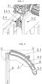
FIG. 2 is a schematic diagram illustrating the connection between the top motor and the hanger arm according to the present invention; -
FIG. 3 is a partial enlarged view of the present invention; -
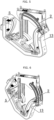
FIG. 4 is a side view of the structure of the present invention; -
FIG. 5 is a diagram illustrating an operating state when the divertor of the present invention is transported; and -
FIG. 6 is a diagram illustrating an operating state when the divertor of the present invention is rotated. -
- 1 base frame
- 2 arc arm
- 3 support point
- 4 roller
- 5 hanger arm
- 6 hanging lug
- 7 motor
- 8 rotary motor
- 9 catching groove
- 10 second gear
- 11 first reducer
- 12 second reducer
- 13 divertor
- 2-1 second rack
- 2-2 arc-shaped groove
- 2-3 connecting member
- 5-1 first rack
- 5-2 first connecting member
- 5-3 second connecting member
- 11-1 first gear
- The technical solutions of the present invention will be further described below with reference to the accompanying drawings and embodiments.
- As shown in
FIGs. 1-3 , a hoisting mechanism for large heavy-load component in nuclear fusion environment includes a base frame 1, a pair ofhanger arms 5, and a pair ofarc arms 2. Four corners of the top of the base frame 1 are respectively provided with hanging lugs 6. Atop motor 7 is provided at a front position in the base frame 1, and a pair ofrotary motors 8 are provided at a rear position in the base frame 1. The above-mentioned pair ofhanger arms 5 are arranged on the left and right sides of the base frame 1 and face each other. A second connecting member 5-3 fixedly connected with a first connecting member 5-2 is fixedly mounted on the upper portion of eachhanger arm 5, a lower portion of each of thehanger arm 5 extends downward to beyond the bottom of the base frame 1, and the opposite surfaces of the lower ends of eachhanger arm 5 are respectively formed into protruding surfaces, and aroller 4 is respectively mounted rotatably on the protruding surface. In addition, the output shaft of thetop motor 7 is drive-connected with the first gear 11-1. The front and rear sides of the first gear 11-1 at the bottom of the base frame 1 are respectively provided with catchinggrooves 9 extending along the left-right direction of the base frame 1, the above-mentioned first connecting member 5-2 is caught in the catchinggroove 9 and can slide in the catchinggroove 9. That is, thehanger arms 5, the first connecting member 5-2, and the second connecting member 5-3 are fixedly and integrally connected, and since the catchinggrooves 9 are located on the front and rear sides of the first gear 11-1 respectively, the above-mentioned first connecting members 5-2 slidably mounted in the catchinggrooves 9 are actually also located on the front and rear sides of the first gear 11-1. In other words, the first connecting members 5-2 caught in the catchinggrooves 9 face each other across the first gear 11-1. In addition, first racks 5-1 are respectively disposed on the opposite surfaces of each first connecting member 5-2, and the above-mentioned first gear 11-1 can be drive-engaged with the first rack 5-1 at the same time. In this way, the power of thetop motor 7 is transmitted to the first rack 5-1 via the first gear 11-1, and drives the first connecting member 5-2 to slide back and forth in the respective catchinggrooves 9, so that the twohanger arms 5 can move in opposite directions relative to each other. In other words, the twohanger arms 5 can move oppositely to be close to or away from each other along the left-right direction of the base frame 1, so as to realize the clamping and releasing of thedivertor 13 by theroller 4 located at the lower end. The twoarc arms 2 are arranged on the left and right sides of the base frame 1, and the outer arc surface of each of thearc arm 2 faces upward. Each of thearc arm 2 is respectively provided with an arc-shaped groove 2-2 corresponding to a shape of the arc arm, and the arc-shaped groove 2-2 penetrates through thearc arm 2 in the left-right direction respectively. A second rack 2-1 corresponding to the shape of thearc arm 2 is respectively provided on the outer arc surface of each of thearc arms 2, an arcuate length of the second rack 2-1 is smaller than an arcuate length of the outer arc surface of thearc arm 2. On both sides of the base frame 1, twosupport points 3 are respectively provided on the center line of thearc arm 2, respectively, thearc arms 2 on each side are slidably fitted to the respective support points 3 on the corresponding side through the respective arc-shaped groove 2-2, and one end of thearc arm 2 extends forward and upward, the other end of thearc arm 2 extends rearward and downward to beyond the bottom of the base frame 1. Connecting members 2-3 are respectively mounted on the other ends of the twoarc arms 2. The center of theroller 4 at the lower end of thehanger arm 5 is concentric with the circle where thearc arm 2 on the corresponding side is located. The left and right sides of the base frame 1 are also rotatably mounted withsecond gears 10 corresponding to the positions of therotary motor 8, respectively, thesecond gears 10 are respectively drive-engaged with the second racks 2-1 on the outer arc surfaces of thearc arm 2 on the corresponding side, the output shafts of the tworotary motors 8 are respectively in a one-to-one correspondence with the twosecond gears 10 for transmission connection. - The
support point 3 is a rotating wheel that is rotatably mounted on the corresponding side of the base frame 1, and the rotating wheel is respectively located in the arc-shaped groove 2-2 of thearc arm 2 on the corresponding side to provide support to thearc arm 2. - The output shaft of the
top motor 7 is connected with the input shaft of a 90-degree anglefirst reducer 11, and the first gear 11-1 is fixedly mounted on the output shaft of the 90-degree angle reducer 11. The first gear racks 5-1 on both sides are driven by the first gear 11-1 to drive the sliding of the first connecting member 5-2 and through the sliding of the first connecting member 5-2, thehanger arm 5 is extended and retracted through the second connecting member 5-3 (the twohanger arms 5 can move oppositely to be close to or away from each other along the left-right direction of the base frame 1). The output shaft of each of therotary motors 8 is respectively connected with the input shaft of the 90-degree angle reducer 12, and the output shafts of the two 90-degree angle second reducers 12 are coaxially connected to the twosecond gears 10 in a one-to-one correspondence. - As shown in
FIG. 5 , during transferring, thedivertor 13 is jointly held by the twohanger arms 5 and the twoarc arms 2. As shown inFIG. 6 , when thedivertor 13 needs to be rotated, thearc arm 2 is extended to realize the rotation of thedivertor 13.
Claims (11)
- A hoisting mechanism for large heavy-load component in nuclear fusion environment, the hoisting mechanism comprising:a base frame (1), a pair of hanger arms (5), a top motor (7) is provided at a front position in the base frame (1),wherein an output shaft of the top motor (7) is connected with a first gear (11-1),wherein the pair of hanger arms (5) are respectively arranged on left and right sides of the base frame (1) and opposite to each other; at the front position in the base frame (1) and on an upper portion of each of the hanger arms (5), first racks (5-1) are respectively provided on front and rear sides of the first gear (11-1) and opposite to each other; the first gear (11-1) is engageable with the two opposing first racks (5-1) at the same time; and a lower portion of each of the pair of hanger arms (5) extends downward beyond a bottom of the base frame (1),characterized in that the hoisting mechanism further comprises a pair of arc arms (2), and rotary motors (8) are provided at a rear position in the base frame (1),wherein the pair of arc arms (2) are respectively arranged on the left and right sides of the base frame (1); an outer arc surface of each of the arc arms (2) faces upward, one end thereof extends forward and upward, and the other end thereof extends rearward and downward beyond the bottom of the base frame (1); each of the arc arms (2) is respectively provided with an arc-shaped groove (2-2) corresponding to a shape of the arc arm (2) and penetrating through the arc arm (2) in a left-right direction; a second rack (2-1) corresponding to the shape of the arc arm (2) is respectively provided on the outer arc surface of each of the arc arms (2); and a plurality of support points are respectively provided on the left and right sides of the base frame (1) which are arranged in an arc shape matching the arc arm (2), and each of the arc arms (2) is slidably fitted to the respective support points on the corresponding side through the respective arc-shaped groove (2-2), andwherein second gears (10) are respectively mounted on the left and right sides of the base frame (1) at positions corresponding to the rotary motors (8), the second gear (10) is respectively drive-engaged with the second rack (2-1) of the arc arm (2) on the corresponding side, and an output shaft of the rotary motor (8) is drive-connected with the second gear (10).
- The hoisting mechanism according to claim 1, wherein four corner positions of a top of the base frame (1) are respectively connected with a hanging lug (6).
- The hoisting mechanism according to claim 1, wherein each of the support points is a rotating wheel that is rotatably mounted on the base frame (1), and the rotating wheel is respectively located in the arc-shaped groove (2-2) of the arc arm (2) on the corresponding side to provide support to the arc arm (2).
- The hoisting mechanism according to claim 1, wherein an arcuate length of the second rack (2-1) is smaller than an arcuate length of the outer arc surface of the arc arm (2).
- The hoisting mechanism according to claim 1, wherein,an inner surface of a lower end of each of the pair of hanger arms (5) is respectively formed into a protruding surface, and a roller (4) is respectively mounted rotatably on the protruding surface; andthe roller (4) is concentric with the arc arm (2) on the corresponding side.
- The hoisting mechanism according to claim 1, wherein an output shaft of the top motor (7) is connected with an input shaft of a 90-degree angle reducer, and the first gear (11-1) is fixedly mounted on an output shaft of the 90-degree angle reducer.
- The hoisting mechanism according to claim 1, wherein,the number of the rotary motors (8) is two; andthe output shaft of each of the rotary motors (8) is respectively connected with an input shaft of a 90-degree angle reducer, and an output shaft of each of the 90-degree angle reducers is respectively connected coaxially with one of the second gears (10).
- The hoisting mechanism according to claim 1, wherein,catching grooves (9) extending along the left-right direction of the base frame (1) are respectively provided on the front and rear sides of the first gear (11-1) at the bottom of the base frame (1);a first connecting member (5-2) is respectively provided on the upper portion of each of the hanger arms (5), each of the first racks (5-1) is respectively fixed on the corresponding first connecting member (5-2), and the first connecting member (5-2) is slidably caught in the corresponding catching groove (9);the top motor (7) drives the first connecting members (2-3) to slide back and forth in the respective catching grooves (9) through the first gear (11-1) and the first racks (5-1) engaged with the first gear (11-1), so that the hanger arms (5) move oppositely to be close to or away from each other along the left-right direction of the base frame (1); anda lower portion of each of the hanger arms (5) is provided with a protruding roller (4).
- The hoisting mechanism according to claim 1, wherein,the arc arms (2) are mounted on opposite sides of the base frame (1), the rotary motor (8) drives the arc arm (2) through the second gear (10) and the second rack (2-1) provided on the arc arm (2), so that the arc arm (2) moves along the arc shape determined by the plurality of support points; anda lower portion of each of the arc arms (2) is provided with a connecting member (2-3).
- The hoisting mechanism according to claim 1, wherein,an inner surface of a lower end of each of the pair of hanger arms (5) is respectively formed into a protruding surface, and a roller (4) is respectively mounted rotatably on the protruding surface;the roller (4) and the arc arm (2) on the corresponding side are located on a concentric circle; andwhen the hanger arms (5) and the arc arms (2) are both connected to a divertor component to be transported, the arc arms (2) are driven to rotate the divertor component along an arc concentric with the rollers (4).
- The hoisting mechanism according to claim 1, wherein,catching grooves (9)extending along the left-right direction of the base frame (1) are respectively provided on the front and rear sides of the first gear (11-1) at the bottom of the base frame (1);a second connecting member (5-3) fixedly connected with a first connecting member (5-2) is respectively provided on the upper portion of each of the hanger arms (5), the first connecting member (5-2) is slidably caught in the corresponding catching groove (9), and each of the first racks (5-1) is respectively fixed on the corresponding first connecting member (5-2);the top motor (7) drives the first connecting members (5-2) to slide back and forth in the respective catching grooves (9) through the first gear (11-1) and the first racks (5-1) engaged with the first gear (11-1), so that the two hanger arms (5) move oppositely at the same time to be close to or away from each other along the left-right direction of the base frame (1); anda lower portion of each of the hanger arms (5) is provided with a protruding roller (4).
Applications Claiming Priority (2)
| Application Number | Priority Date | Filing Date | Title |
|---|---|---|---|
| CN201911034725.1A CN110723638B (en) | 2019-10-29 | 2019-10-29 | A hoisting mechanism for large and heavy-duty components in nuclear environment |
| PCT/CN2020/122740 WO2021083025A1 (en) | 2019-10-29 | 2020-10-22 | Hoisting mechanism for large heavy-load component in nuclear fusion environment |
Publications (4)
| Publication Number | Publication Date |
|---|---|
| EP4053064A1 EP4053064A1 (en) | 2022-09-07 |
| EP4053064A4 EP4053064A4 (en) | 2023-11-29 |
| EP4053064B1 true EP4053064B1 (en) | 2025-04-16 |
| EP4053064C0 EP4053064C0 (en) | 2025-04-16 |
Family
ID=69222224
Family Applications (1)
| Application Number | Title | Priority Date | Filing Date |
|---|---|---|---|
| EP20883497.8A Active EP4053064B1 (en) | 2019-10-29 | 2020-10-22 | Hoisting mechanism for large heavy-load component in nuclear fusion environment |
Country Status (3)
| Country | Link |
|---|---|
| EP (1) | EP4053064B1 (en) |
| CN (1) | CN110723638B (en) |
| WO (1) | WO2021083025A1 (en) |
Families Citing this family (3)
| Publication number | Priority date | Publication date | Assignee | Title |
|---|---|---|---|---|
| CN110723638B (en) * | 2019-10-29 | 2020-09-29 | 中国科学院合肥物质科学研究院 | A hoisting mechanism for large and heavy-duty components in nuclear environment |
| CN112722946A (en) * | 2020-12-29 | 2021-04-30 | 江苏虞美人纺织品有限公司 | Unloader convenient to textile fabric |
| CN116733799B (en) * | 2023-06-26 | 2025-12-12 | 核工业西南物理研究院 | A hydraulic power system for a fusion device |
Family Cites Families (14)
| Publication number | Priority date | Publication date | Assignee | Title |
|---|---|---|---|---|
| DE2648665C3 (en) * | 1976-10-27 | 1980-02-07 | Bartholomy & Co, 5160 Dueren | Device for gripping and tilting heavy objects, in particular rolls of paper or other web-shaped materials |
| DE3517460A1 (en) * | 1985-05-14 | 1986-11-20 | Mannesmann AG, 4000 Düsseldorf | Gripper |
| JP2001063954A (en) * | 1999-08-30 | 2001-03-13 | Sumikin Kansai Kogyo Kk | Body lifting jig for rolling stock |
| JP5861255B2 (en) * | 2011-01-12 | 2016-02-16 | セイコーエプソン株式会社 | Robot hand and robot |
| CN203284054U (en) * | 2013-05-31 | 2013-11-13 | 上海菲格瑞特汽车工程科技有限公司 | Car body hoisting component |
| CN104210930B (en) * | 2014-09-02 | 2016-08-24 | 中国科学院等离子体物理研究所 | A kind of protection mechanism for the transhipment of nuclear fusion device neck tube inner part |
| JP6468871B2 (en) * | 2015-02-03 | 2019-02-13 | キヤノン株式会社 | Robot hand control method and robot apparatus |
| CN204823679U (en) * | 2015-08-17 | 2015-12-02 | 常山优博特机电科技有限公司 | Heavy automobile wheel hub safety hoist |
| CN110216709B (en) * | 2018-03-01 | 2023-02-17 | 安徽凌坤智能科技有限公司 | Improved mechanical paw |
| CN108529522B (en) * | 2018-06-26 | 2024-03-29 | 奥莱特汽车科技有限公司 | Lifting machine for lifting rotatable sheet metal workshop |
| CN109484969A (en) * | 2018-11-26 | 2019-03-19 | 黎清华 | A kind of container hanging device of logistics unmanned plane |
| CN209455945U (en) * | 2018-12-28 | 2019-10-01 | 广州佳乂特起重机电工程有限公司 | A kind of track reuse holding frame |
| CN110092300B (en) * | 2019-05-10 | 2024-04-26 | 张家港市瑞昌智能机器系统有限公司 | I-shaped wheel embraces installation manipulator |
| CN110723638B (en) * | 2019-10-29 | 2020-09-29 | 中国科学院合肥物质科学研究院 | A hoisting mechanism for large and heavy-duty components in nuclear environment |
-
2019
- 2019-10-29 CN CN201911034725.1A patent/CN110723638B/en active Active
-
2020
- 2020-10-22 WO PCT/CN2020/122740 patent/WO2021083025A1/en not_active Ceased
- 2020-10-22 EP EP20883497.8A patent/EP4053064B1/en active Active
Also Published As
| Publication number | Publication date |
|---|---|
| EP4053064A4 (en) | 2023-11-29 |
| CN110723638B (en) | 2020-09-29 |
| EP4053064A1 (en) | 2022-09-07 |
| CN110723638A (en) | 2020-01-24 |
| WO2021083025A1 (en) | 2021-05-06 |
| EP4053064C0 (en) | 2025-04-16 |
Similar Documents
| Publication | Publication Date | Title |
|---|---|---|
| EP4053064A1 (en) | Hoisting mechanism for large heavy-load component in nuclear fusion environment | |
| CN105261400A (en) | Remote operation transfer scheme for component maintenance of nuclear fusion apparatus | |
| CN220710267U (en) | Flower basket turning device | |
| CN110648774A (en) | A vehicle-mounted mobile refueling system and refueling method | |
| CN207257808U (en) | A kind of logistics loads instrument with Drop and pull transport | |
| CN214312926U (en) | Amorphous alloy transformer core stack-up device | |
| WO2026011671A1 (en) | Track docking and conveying device | |
| CN103568003B (en) | The long-range airborne carrier mechanical arm of vacuum chamber is equipped towards MCF | |
| CN221792730U (en) | Solid-state module quick-changing device of fuel cell system | |
| CN104210930A (en) | Protecting mechanism for transporting inner part of neck pipe of nuclear fusion device | |
| CN112372350A (en) | Tool changing mechanism with unlocking knife | |
| CN112489822B (en) | Cladding maintenance transfer mechanism for nuclear fusion device | |
| CN213140120U (en) | Reducing furnace cooling and receiving device | |
| CN215249349U (en) | Special maintenance elevating gear of oil field special type vehicle | |
| CN209743541U (en) | L-shaped tower type speed reducer | |
| CN204624704U (en) | The aluminium ingot stacking translating device of the mobile particularity of a kind of effective raising | |
| CN211371168U (en) | AGV dolly lifts reduction gear | |
| CN108341203A (en) | A kind of commutation transfer platform translation lifting mechanism control system and method | |
| CN115497645A (en) | control rod drive system | |
| CN216104143U (en) | Rotary conveying roller way with double power systems | |
| US3140238A (en) | Charging and service machine for gas-cooled reactors | |
| CN218841623U (en) | Electric pile car suitable for battery loading and unloading | |
| CN217554946U (en) | Push chain system of small-sized movable nuclear reactor fuel transfer device | |
| CN216807990U (en) | Lifting device for mounting power equipment for power engineering | |
| CN217251630U (en) | Drawing machine transport mechanism for umbrella rib processing |
Legal Events
| Date | Code | Title | Description |
|---|---|---|---|
| STAA | Information on the status of an ep patent application or granted ep patent |
Free format text: STATUS: THE INTERNATIONAL PUBLICATION HAS BEEN MADE |
|
| PUAI | Public reference made under article 153(3) epc to a published international application that has entered the european phase |
Free format text: ORIGINAL CODE: 0009012 |
|
| STAA | Information on the status of an ep patent application or granted ep patent |
Free format text: STATUS: REQUEST FOR EXAMINATION WAS MADE |
|
| 17P | Request for examination filed |
Effective date: 20220527 |
|
| AK | Designated contracting states |
Kind code of ref document: A1 Designated state(s): AL AT BE BG CH CY CZ DE DK EE ES FI FR GB GR HR HU IE IS IT LI LT LU LV MC MK MT NL NO PL PT RO RS SE SI SK SM TR |
|
| DAV | Request for validation of the european patent (deleted) | ||
| DAX | Request for extension of the european patent (deleted) | ||
| A4 | Supplementary search report drawn up and despatched |
Effective date: 20231030 |
|
| RIC1 | Information provided on ipc code assigned before grant |
Ipc: G21D 1/02 20060101ALI20231024BHEP Ipc: B66C 13/08 20060101ALI20231024BHEP Ipc: B66C 1/42 20060101AFI20231024BHEP |
|
| GRAP | Despatch of communication of intention to grant a patent |
Free format text: ORIGINAL CODE: EPIDOSNIGR1 |
|
| STAA | Information on the status of an ep patent application or granted ep patent |
Free format text: STATUS: GRANT OF PATENT IS INTENDED |
|
| INTG | Intention to grant announced |
Effective date: 20241218 |
|
| GRAS | Grant fee paid |
Free format text: ORIGINAL CODE: EPIDOSNIGR3 |
|
| GRAA | (expected) grant |
Free format text: ORIGINAL CODE: 0009210 |
|
| STAA | Information on the status of an ep patent application or granted ep patent |
Free format text: STATUS: THE PATENT HAS BEEN GRANTED |
|
| AK | Designated contracting states |
Kind code of ref document: B1 Designated state(s): AL AT BE BG CH CY CZ DE DK EE ES FI FR GB GR HR HU IE IS IT LI LT LU LV MC MK MT NL NO PL PT RO RS SE SI SK SM TR |
|
| REG | Reference to a national code |
Ref country code: GB Ref legal event code: FG4D |
|
| REG | Reference to a national code |
Ref country code: CH Ref legal event code: EP Ref country code: DE Ref legal event code: R096 Ref document number: 602020049713 Country of ref document: DE |
|
| REG | Reference to a national code |
Ref country code: IE Ref legal event code: FG4D |
|
| U01 | Request for unitary effect filed |
Effective date: 20250429 |
|
| U07 | Unitary effect registered |
Designated state(s): AT BE BG DE DK EE FI FR IT LT LU LV MT NL PT RO SE SI Effective date: 20250515 |
|
| PG25 | Lapsed in a contracting state [announced via postgrant information from national office to epo] |
Ref country code: ES Free format text: LAPSE BECAUSE OF FAILURE TO SUBMIT A TRANSLATION OF THE DESCRIPTION OR TO PAY THE FEE WITHIN THE PRESCRIBED TIME-LIMIT Effective date: 20250416 |
|
| PG25 | Lapsed in a contracting state [announced via postgrant information from national office to epo] |
Ref country code: GR Free format text: LAPSE BECAUSE OF FAILURE TO SUBMIT A TRANSLATION OF THE DESCRIPTION OR TO PAY THE FEE WITHIN THE PRESCRIBED TIME-LIMIT Effective date: 20250717 Ref country code: NO Free format text: LAPSE BECAUSE OF FAILURE TO SUBMIT A TRANSLATION OF THE DESCRIPTION OR TO PAY THE FEE WITHIN THE PRESCRIBED TIME-LIMIT Effective date: 20250716 |
|
| PG25 | Lapsed in a contracting state [announced via postgrant information from national office to epo] |
Ref country code: PL Free format text: LAPSE BECAUSE OF FAILURE TO SUBMIT A TRANSLATION OF THE DESCRIPTION OR TO PAY THE FEE WITHIN THE PRESCRIBED TIME-LIMIT Effective date: 20250416 |
|
| PG25 | Lapsed in a contracting state [announced via postgrant information from national office to epo] |
Ref country code: HR Free format text: LAPSE BECAUSE OF FAILURE TO SUBMIT A TRANSLATION OF THE DESCRIPTION OR TO PAY THE FEE WITHIN THE PRESCRIBED TIME-LIMIT Effective date: 20250416 |
|
| PG25 | Lapsed in a contracting state [announced via postgrant information from national office to epo] |
Ref country code: RS Free format text: LAPSE BECAUSE OF FAILURE TO SUBMIT A TRANSLATION OF THE DESCRIPTION OR TO PAY THE FEE WITHIN THE PRESCRIBED TIME-LIMIT Effective date: 20250716 |
|
| PG25 | Lapsed in a contracting state [announced via postgrant information from national office to epo] |
Ref country code: IS Free format text: LAPSE BECAUSE OF FAILURE TO SUBMIT A TRANSLATION OF THE DESCRIPTION OR TO PAY THE FEE WITHIN THE PRESCRIBED TIME-LIMIT Effective date: 20250816 |
|
| U20 | Renewal fee for the european patent with unitary effect paid |
Year of fee payment: 6 Effective date: 20251011 |
|
| PG25 | Lapsed in a contracting state [announced via postgrant information from national office to epo] |
Ref country code: SM Free format text: LAPSE BECAUSE OF FAILURE TO SUBMIT A TRANSLATION OF THE DESCRIPTION OR TO PAY THE FEE WITHIN THE PRESCRIBED TIME-LIMIT Effective date: 20250416 |
|
| PG25 | Lapsed in a contracting state [announced via postgrant information from national office to epo] |
Ref country code: CZ Free format text: LAPSE BECAUSE OF FAILURE TO SUBMIT A TRANSLATION OF THE DESCRIPTION OR TO PAY THE FEE WITHIN THE PRESCRIBED TIME-LIMIT Effective date: 20250416 |
|
| PG25 | Lapsed in a contracting state [announced via postgrant information from national office to epo] |
Ref country code: SK Free format text: LAPSE BECAUSE OF FAILURE TO SUBMIT A TRANSLATION OF THE DESCRIPTION OR TO PAY THE FEE WITHIN THE PRESCRIBED TIME-LIMIT Effective date: 20250416 |
|
| PLBE | No opposition filed within time limit |
Free format text: ORIGINAL CODE: 0009261 |
|
| STAA | Information on the status of an ep patent application or granted ep patent |
Free format text: STATUS: NO OPPOSITION FILED WITHIN TIME LIMIT |
|
| REG | Reference to a national code |
Ref country code: CH Ref legal event code: L10 Free format text: ST27 STATUS EVENT CODE: U-0-0-L10-L00 (AS PROVIDED BY THE NATIONAL OFFICE) Effective date: 20260225 |
|
| 26N | No opposition filed |
Effective date: 20260119 |