EP4053010A1 - Stern platform for boats - Google Patents
Stern platform for boats Download PDFInfo
- Publication number
- EP4053010A1 EP4053010A1 EP22152957.1A EP22152957A EP4053010A1 EP 4053010 A1 EP4053010 A1 EP 4053010A1 EP 22152957 A EP22152957 A EP 22152957A EP 4053010 A1 EP4053010 A1 EP 4053010A1
- Authority
- EP
- European Patent Office
- Prior art keywords
- platform
- bracket
- actuator
- rocker arm
- rotatably connected
- Prior art date
- Legal status (The legal status is an assumption and is not a legal conclusion. Google has not performed a legal analysis and makes no representation as to the accuracy of the status listed.)
- Granted
Links
Images

Classifications
-
- B—PERFORMING OPERATIONS; TRANSPORTING
- B63—SHIPS OR OTHER WATERBORNE VESSELS; RELATED EQUIPMENT
- B63B—SHIPS OR OTHER WATERBORNE VESSELS; EQUIPMENT FOR SHIPPING
- B63B27/00—Arrangement of ship-based loading or unloading equipment for cargo or passengers
- B63B27/14—Arrangement of ship-based loading or unloading equipment for cargo or passengers of ramps, gangways or outboard ladders ; Pilot lifts
- B63B27/146—Pilot ladders or similar outboard ladders, e.g. bathing ladders; Pilot lifts
-
- B—PERFORMING OPERATIONS; TRANSPORTING
- B63—SHIPS OR OTHER WATERBORNE VESSELS; RELATED EQUIPMENT
- B63B—SHIPS OR OTHER WATERBORNE VESSELS; EQUIPMENT FOR SHIPPING
- B63B29/00—Accommodation for crew or passengers not otherwise provided for
- B63B29/02—Cabins or other living spaces; Construction or arrangement thereof
- B63B2029/022—Bathing platforms
Definitions
- the present invention relates to a stern platform for boats.
- the invention relates to a mobile and articulated platform, for example installable on the sides or stern of boats or vessels, and designed to be extendable, so as to be able to switch from a retracted or rest configuration, to an extended or use configuration, and vice versa, by means of an articulated quadrilateral.
- Platforms are used to increase the walkable space available to passengers and crew, usable, for example, during the periods in which the boat is at sea, for activities of various kinds.
- Platforms are normally laid out when needed, and are kept oriented along a direction parallel to the deck of the boat itself.
- dashboards are not at all convenient for the end user to make dashboards larger than a certain size, especially since their width can be a problem when they are in their retracted or resting configuration.
- decks are permanently attached to vessels, and are moved between the rest configuration and the use configuration by appropriate equipment and handling systems.
- Another object of the invention is to provide a stern platform having a small encumbrance, especially when the dashboard is not in use.
- FIG. 1-3 there is depicted a platform 100, installable on the hull of a boat (not shown), schematized by means of a fastening surface 11.
- the operation and structure of the platform 100 is based on two mechanically identical assemblies comprising components such as actuators, rods, and other rigid elements connected together to compose an articulated quadrilateral.
- each assembly or quadrilateral of the platform 100 to the fastening surface 11 of the craft is accomplished by means of a bracket 1.
- the bracket 1 has four pivot points or hinges for connecting the same number of rigid elements:
- rocker arms 4, 21 and 22 are parallel to each other, and are in turn connected to a support member 3, located opposite the bracket 1, via respective fourth hinges 734 and fifth hinges 723.
- the bracket 1, the rocker arms 4,21 and 22, together with the support member 3 form for each assembly the articulated quadrilateral for moving the platform 100.
- a first and second fastening elements 81, 82 are rigidly connected to the support member 3, so as to keep themselves oriented in a horizontal direction; to them a support surface or walkway (not shown for simplicity) of the platform 100 is attached.
- Movement of the platform 100 between a retracted configuration ( Fig. 2 ) and an extended configuration ( Fig. 3 ) is accomplished by rotation of the first rocker arm 4 about the first hinges 714 and the second and third rockers 21, 22 about the second hinges 712.
- the actuator 5 is preferably of the screw type, and has a worm screw 51 which, rotating about its axis X, allows the translation of a nut 52 by sliding on the surface of the screw 51 itself.
- the nut 52 is rigidly connected to a plate 6, which in turn is rotatably connected to the first rocker arm 4 by means of sixth hinges 764.
- the plate 6 is pulled along the X-axis of the worm screw 51 by the translational movement of the nut 52 sliding on the screw 51 itself, and determines the extension or contraction of the articulated quadrilateral depending on whether the movement itself occurs away from or towards the bracket 1.
- the receding of the nut 52 i.e. the extension of the actuator 5, causes the first rocker arm 4, connected to the nut 52 by the plate 6, to rotate about the first hinge 714.
- the support member 3 is translated by the rotation of the first rocker arm 4, simultaneous with those of the second and third rockers 21, 22 around the second hinges 712.
- the first and second fasteners 81, 82 which are rigidly connected to the support member 3, are in a lowered position relative to the initial retracted configuration of the platform 100.
- the actuator 5 includes a motor 506, which is connected to the screw 51 by a gearbox 507.
- An enclosure 505 contains and protects the motor 506 and gearbox 507 from moisture.
- a sealing member 508 is positioned at the end of the actuator 5 from which the screw 51 extends; said sealing member 508 is shaped to isolate the gearbox 507 - screw 51 junction from water intrusion.
- Gaskets 518 are also positioned at the interfaces between screw 51 and sealing element 508.
Landscapes
- Chemical & Material Sciences (AREA)
- Engineering & Computer Science (AREA)
- Combustion & Propulsion (AREA)
- Mechanical Engineering (AREA)
- Ocean & Marine Engineering (AREA)
- Transmission Devices (AREA)
- Blow-Moulding Or Thermoforming Of Plastics Or The Like (AREA)
Abstract
Description
- The present invention relates to a stern platform for boats.
- More particularly, the invention relates to a mobile and articulated platform, for example installable on the sides or stern of boats or vessels, and designed to be extendable, so as to be able to switch from a retracted or rest configuration, to an extended or use configuration, and vice versa, by means of an articulated quadrilateral.
- They are known in the nautical sector platforms externally associated to leisure boats or cruise ships of movable and tilting type, applied to the boats by means of movement apparatus of conventional type (actuators, pistons, chains, etc.).
- Platforms are used to increase the walkable space available to passengers and crew, usable, for example, during the periods in which the boat is at sea, for activities of various kinds.
- Platforms are normally laid out when needed, and are kept oriented along a direction parallel to the deck of the boat itself.
- When not in use, some types of decks must be manually disassembled to be relocated in a separate area so that they do not impede the maneuvering of the vessel and the movements of the crew on board.
- One of the main problems of the known decks is represented by the excessive encumbrance, especially during those situations in which they are not used, for example when the boat is sailing, or when it is at anchor in port.
- The problem of obstruction becomes more and more relevant as the size of the dashboard increases.
- In fact, for practicality reasons, it is not at all convenient for the end user to make dashboards larger than a certain size, especially since their width can be a problem when they are in their retracted or resting configuration.
- In addition, some types of decks are permanently attached to vessels, and are moved between the rest configuration and the use configuration by appropriate equipment and handling systems.
- These systems can cause some operational inconveniences, especially with regard to their reliability and maintenance.
- In fact, the aggressive environmental conditions of marine and/or lake environments (high humidity and presence of salts), together with the large number of mechanical components usually required for the realization of the mechanisms, make handling systems particularly susceptible to failures and malfunctions.
- A further drawback of known handling systems concerns the excessive use of actuators and hydraulic devices in general, which represent the currently preferred alternative in the sector.
- However, environmental problems that these systems can cause have been known for some time, following the release of quantities of oil and/or lubricating products that, although small, are protracted over time.
- It is, therefore, a principal object of the present invention to provide a stern platform for boats which solves the mentioned drawbacks.
- In particular, it is an object of the present invention to provide a stern platform for boats having a handling system which is simple to construct and reliable with respect to the known technique.
- Another object of the invention is to provide a stern platform having a small encumbrance, especially when the dashboard is not in use.
- In addition, it is an object of the invention to provide a stern platform for boats having a low environmental impact.
- It is further an object of the present invention to provide a stern platform that is easy and inexpensive to make and use, in view of the advantages achieved.
- These and other purposes are achieved by a stern platform for boats according to the attached
claim 1; further details and technical features of the invention are contained in the attached dependent claims. - The present invention will now be described, by way of example but not limitation, according to some of its preferred embodiments, and with the aid of the attached figures, wherein:
-
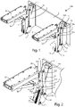
Figure 1 is a perspective view of the stern platform for boats according to the present invention in a retracted configuration; -
Figure 2 shows a detail of the platform in the configuration depicted infigure 1 ; -
Figure 3 shows a detail of the stern platform for boats according to the invention in an extended configuration; -
Figure 4 is a sectional view of a detail of the platform moving system according to the invention. - Referring to
Figures 1-3 , there is depicted aplatform 100, installable on the hull of a boat (not shown), schematized by means of afastening surface 11. - The operation and structure of the
platform 100 is based on two mechanically identical assemblies comprising components such as actuators, rods, and other rigid elements connected together to compose an articulated quadrilateral. - The coupling of each assembly or quadrilateral of the
platform 100 to thefastening surface 11 of the craft is accomplished by means of abracket 1. - The
bracket 1 has four pivot points or hinges for connecting the same number of rigid elements: - a
first rocker arm 4, connected viafirst hinges 714; - a
second rocker arm 21 and athird rocker arm 22, connected viasecond hinges 712; - an
actuator 5, connected to thebracket 1 by means of athird hinge 751 and used to move thefirst rocker arm 4. - The
rocker arms support member 3, located opposite thebracket 1, via respectivefourth hinges 734 andfifth hinges 723. - The
bracket 1, therocker arms support member 3 form for each assembly the articulated quadrilateral for moving theplatform 100. - Preferably, a first and
second fastening elements support member 3, so as to keep themselves oriented in a horizontal direction; to them a support surface or walkway (not shown for simplicity) of theplatform 100 is attached. - Movement of the
platform 100 between a retracted configuration (Fig. 2 ) and an extended configuration (Fig. 3 ) is accomplished by rotation of thefirst rocker arm 4 about thefirst hinges 714 and the second andthird rockers second hinges 712. - The
actuator 5 is preferably of the screw type, and has aworm screw 51 which, rotating about its axis X, allows the translation of anut 52 by sliding on the surface of thescrew 51 itself. - The
nut 52 is rigidly connected to aplate 6, which in turn is rotatably connected to thefirst rocker arm 4 by means ofsixth hinges 764. - Operationally, the
plate 6 is pulled along the X-axis of theworm screw 51 by the translational movement of thenut 52 sliding on thescrew 51 itself, and determines the extension or contraction of the articulated quadrilateral depending on whether the movement itself occurs away from or towards thebracket 1. - The receding of the
nut 52, i.e. the extension of theactuator 5, causes thefirst rocker arm 4, connected to thenut 52 by theplate 6, to rotate about thefirst hinge 714. - The
support member 3 is translated by the rotation of thefirst rocker arm 4, simultaneous with those of the second andthird rockers second hinges 712. - When the
nut 52 reaches the end of its travel, the translation of thesupport element 3 is complete, and theplatform 100 is in the extended configuration, as shown in the detail ofFigure 3 . - The first and
second fasteners support member 3, are in a lowered position relative to the initial retracted configuration of theplatform 100. - Conversely, when the
nut 52 moves in an approaching direction, and theactuator 5 contracts, thesupport member 3 translates approaching thebracket 1, and thedashboard 100 closes until it reaches the contracted configuration, as shown inFigure 2 . - In other words, when the
actuator 5 is operated in extension, theplatform 100 transitions into the extended configuration by a receding rotation of thefirst rocker arm 4 and a receding translation of thesupport member 3 relative to thebracket 1, whereas, when theactuator 5 is operated in contraction, theplatform 100 transitions into the retracted configuration by an approaching rotation of thefirst rocker arm 4 and an approaching translation of thesupport member 3 relative to thebracket 1.Figure 4 shows a section of theactuator 5. - The
actuator 5 includes amotor 506, which is connected to thescrew 51 by agearbox 507. - An
enclosure 505 contains and protects themotor 506 andgearbox 507 from moisture. - A sealing
member 508 is positioned at the end of theactuator 5 from which thescrew 51 extends; said sealingmember 508 is shaped to isolate the gearbox 507 -screw 51 junction from water intrusion. -
Gaskets 518 are also positioned at the interfaces betweenscrew 51 andsealing element 508. - Advantageously, all components moving the
platform 100 are thus protected in a watertight enclosure. - The invention thus conceived is susceptible to numerous modifications and variations, all of which fall within the scope of protection of the appended claims.
- Furthermore, all details may be replaced by other technically equivalent elements.
- In practice, the materials used as well as the contingent shapes and dimensions may be varied according to the contingent requirements and the state of the art.
- Where construction features and techniques mentioned in the following claims are followed by reference signs or numbers, such reference signs or numbers have been affixed for the sole purpose of increasing the intelligibility of the claims and, accordingly, they do not in any way constitute a limitation on the interpretation of each element identified, by way of example only, by such reference signs or numbers.
Claims (6)
- A mobile stern platform (100) intended to be attached to a surface (11) of a boat, comprisinga bracket (1) configured to be coupled to the surface (11) of the boat,a first, second, and third rocker arms (4, 21, 22,) each rotatably connected to the bracket (11, )a support member (3) for a walking surface, rotatably connected to the first, second and third rocker arms (4, 21, 22) to form an articulated quadrilateral, characterized in comprisingan actuator (5) rotatably connected to the bracket (1) and to the first rocker arm (4) so that, when the actuator (5) is operated in extension, the platform (100) shifts into an extended configuration by means of a rotation of the first rocker arm (4) and of a movement of the support member (3) away from the bracket (1), whereas, when the actuator (5) is actuated in contraction, the platform (100) shifts into a retracted configuration by means of a rotation of the first rocker arm (4) and an advancement of the support element (3) towards the bracket (1).
- Mobile stern platform (100) according to claim 1, characterized in that said actuator (5) is of the screw type and comprisesa worm screw (51) connected to a motor (506),a nut (52), rotatably connected to the first rocker arm (4) by means of a plate (6) and constrained to translate along the worm screw (51), so that a distal translation of the nut (52) along the screw (51) brings the platform (100) into the extended configuration, and so that a proximal translation of the nut (52) brings the platform (100) into the retracted configuration.
- Mobile stern platform (100) according to claim 2, characterized in that the actuator (5) comprises a gearbox (507), connected to the motor (506) and to the worm screw (51), wherein the motor (506) and the gearbox (507) are arranged within a watertight housing (505) having a sealing element (508) in proximity to the worm screw (51).
- Mobile stern platform (100) according to any one of claims 1-3, characterized in that
a first fastening element (81) and a second fastening element (82) are coupled to the support element (3), for connecting a walking surface or platform to the support element (3). - Mobile stern platform (100) according to one of the claims 1-4, characterized in that the rocker arms (4, 21, 22) are connected to the bracket (1) and to the support element (3) by respective hinges (714, 712, 734, 723).
- Mobile stern platform (100) according to one of the claims 1-5, characterized in that the actuator (5) is connected to the bracket (1) by a hinge (751) and the plate (6) is connected to the first rocker arm (4) by a supplementary hinge (764).
Applications Claiming Priority (1)
| Application Number | Priority Date | Filing Date | Title |
|---|---|---|---|
| IT102021000004877A IT202100004877A1 (en) | 2021-03-02 | 2021-03-02 | MOBILE BOARD FOR BOATS |
Publications (2)
| Publication Number | Publication Date |
|---|---|
| EP4053010A1 true EP4053010A1 (en) | 2022-09-07 |
| EP4053010B1 EP4053010B1 (en) | 2026-01-28 |
Family
ID=75937022
Family Applications (1)
| Application Number | Title | Priority Date | Filing Date |
|---|---|---|---|
| EP22152957.1A Active EP4053010B1 (en) | 2021-03-02 | 2022-01-24 | Stern platform for boats |
Country Status (2)
| Country | Link |
|---|---|
| EP (1) | EP4053010B1 (en) |
| IT (1) | IT202100004877A1 (en) |
Citations (3)
| Publication number | Priority date | Publication date | Assignee | Title |
|---|---|---|---|---|
| EP2479104A1 (en) * | 2011-01-20 | 2012-07-25 | H+B technics GmbH & Co. KG | Platform lift for an aquatic vehicle and aquatic vehicle with a platform lift |
| WO2013191715A2 (en) * | 2012-06-22 | 2013-12-27 | John Robertson | Marine lift with pantograph movement |
| DE102018133044A1 (en) * | 2018-12-20 | 2020-06-25 | H + B Technics Gmbh + Co. Kg | Segmented platform for a watercraft |
-
2021
- 2021-03-02 IT IT102021000004877A patent/IT202100004877A1/en unknown
-
2022
- 2022-01-24 EP EP22152957.1A patent/EP4053010B1/en active Active
Patent Citations (3)
| Publication number | Priority date | Publication date | Assignee | Title |
|---|---|---|---|---|
| EP2479104A1 (en) * | 2011-01-20 | 2012-07-25 | H+B technics GmbH & Co. KG | Platform lift for an aquatic vehicle and aquatic vehicle with a platform lift |
| WO2013191715A2 (en) * | 2012-06-22 | 2013-12-27 | John Robertson | Marine lift with pantograph movement |
| DE102018133044A1 (en) * | 2018-12-20 | 2020-06-25 | H + B Technics Gmbh + Co. Kg | Segmented platform for a watercraft |
Also Published As
| Publication number | Publication date |
|---|---|
| EP4053010B1 (en) | 2026-01-28 |
| IT202100004877A1 (en) | 2022-09-02 |
Similar Documents
| Publication | Publication Date | Title |
|---|---|---|
| CA2979909C (en) | Improved mounting and actuation device | |
| EP3022112B1 (en) | Apparatus and method for providing active motion compensation control of an articulated gangway | |
| EP2757037A1 (en) | A foldable element for a retractable thruster and a method for producing such element | |
| EP3168137B1 (en) | Retractable thruster | |
| AU2014302350B2 (en) | Watercraft docking systems and methods of their operation | |
| WO2011135605A2 (en) | Reduced dimensions platform for the landing of an aircraft on an access facility | |
| EP4053010B1 (en) | Stern platform for boats | |
| US9873490B2 (en) | Door systems and methods for boats | |
| KR101334832B1 (en) | Apparatus for controlling flow direction of side thruster | |
| US10618612B2 (en) | Systems and methods related to marine fenders | |
| KR20200105484A (en) | Onboard detachable foldable thrusters for marine vessels and marine vessels | |
| US5246392A (en) | Stern drive system with anti-rotation brace | |
| US12181099B2 (en) | Mounting assembly | |
| EP3895975B1 (en) | Movable platform assembly with translation system | |
| EP4008624B1 (en) | Boat gangway | |
| US3540400A (en) | Ship hull having adjustable bow bulb | |
| US5467728A (en) | Retractable bow diving plane for a submarine | |
| NL2033273B1 (en) | Retractable propulsion system for a marine vessel | |
| US20260109442A1 (en) | Retractable Thruster | |
| GB2621592A (en) | System for attaching a vessel and method for doing the same | |
| WO2022071804A1 (en) | A gangway, vessel, offshore structure and methods | |
| GB2616619A (en) | Apparatus for deploying and recovering an object to and from a platform and method for the same | |
| BE882354A (en) | LIFTABLE STEERING OR OPERATING HUT | |
| PL121578B1 (en) | Mechanism for displacing tiltable ramp-forming cargo port of waterborne craftsom na sudakh |
Legal Events
| Date | Code | Title | Description |
|---|---|---|---|
| PUAI | Public reference made under article 153(3) epc to a published international application that has entered the european phase |
Free format text: ORIGINAL CODE: 0009012 |
|
| STAA | Information on the status of an ep patent application or granted ep patent |
Free format text: STATUS: THE APPLICATION HAS BEEN PUBLISHED |
|
| AK | Designated contracting states |
Kind code of ref document: A1 Designated state(s): AL AT BE BG CH CY CZ DE DK EE ES FI FR GB GR HR HU IE IS IT LI LT LU LV MC MK MT NL NO PL PT RO RS SE SI SK SM TR |
|
| STAA | Information on the status of an ep patent application or granted ep patent |
Free format text: STATUS: REQUEST FOR EXAMINATION WAS MADE |
|
| 17P | Request for examination filed |
Effective date: 20230206 |
|
| RBV | Designated contracting states (corrected) |
Designated state(s): AL AT BE BG CH CY CZ DE DK EE ES FI FR GB GR HR HU IE IS IT LI LT LU LV MC MK MT NL NO PL PT RO RS SE SI SK SM TR |
|
| STAA | Information on the status of an ep patent application or granted ep patent |
Free format text: STATUS: EXAMINATION IS IN PROGRESS |
|
| 17Q | First examination report despatched |
Effective date: 20240515 |
|
| P01 | Opt-out of the competence of the unified patent court (upc) registered |
Free format text: CASE NUMBER: UPC_APP_121014/2023 Effective date: 20230510 |
|
| GRAP | Despatch of communication of intention to grant a patent |
Free format text: ORIGINAL CODE: EPIDOSNIGR1 |
|
| STAA | Information on the status of an ep patent application or granted ep patent |
Free format text: STATUS: GRANT OF PATENT IS INTENDED |
|
| GRAS | Grant fee paid |
Free format text: ORIGINAL CODE: EPIDOSNIGR3 |
|
| INTG | Intention to grant announced |
Effective date: 20251124 |
|
| GRAA | (expected) grant |
Free format text: ORIGINAL CODE: 0009210 |
|
| STAA | Information on the status of an ep patent application or granted ep patent |
Free format text: STATUS: THE PATENT HAS BEEN GRANTED |
|
| AK | Designated contracting states |
Kind code of ref document: B1 Designated state(s): AL AT BE BG CH CY CZ DE DK EE ES FI FR GB GR HR HU IE IS IT LI LT LU LV MC MK MT NL NO PL PT RO RS SE SI SK SM TR |
|
| REG | Reference to a national code |
Ref country code: CH Ref legal event code: F10 Free format text: ST27 STATUS EVENT CODE: U-0-0-F10-F00 (AS PROVIDED BY THE NATIONAL OFFICE) Effective date: 20260128 Ref country code: GB Ref legal event code: FG4D |
|
| REG | Reference to a national code |
Ref country code: IE Ref legal event code: FG4D |
|
| REG | Reference to a national code |
Ref country code: DE Ref legal event code: R096 Ref document number: 602022029031 Country of ref document: DE |