EP4052998A1 - A frame structure for a vehicle - Google Patents
A frame structure for a vehicle Download PDFInfo
- Publication number
- EP4052998A1 EP4052998A1 EP21160252.9A EP21160252A EP4052998A1 EP 4052998 A1 EP4052998 A1 EP 4052998A1 EP 21160252 A EP21160252 A EP 21160252A EP 4052998 A1 EP4052998 A1 EP 4052998A1
- Authority
- EP
- European Patent Office
- Prior art keywords
- vehicle
- arrangement
- frame structure
- load bearing
- structure according
- Prior art date
- Legal status (The legal status is an assumption and is not a legal conclusion. Google has not performed a legal analysis and makes no representation as to the accuracy of the status listed.)
- Granted
Links
Images
Classifications
-
- B—PERFORMING OPERATIONS; TRANSPORTING
- B62—LAND VEHICLES FOR TRAVELLING OTHERWISE THAN ON RAILS
- B62D—MOTOR VEHICLES; TRAILERS
- B62D21/00—Understructures, i.e. chassis frame on which a vehicle body may be mounted
-
- B—PERFORMING OPERATIONS; TRANSPORTING
- B62—LAND VEHICLES FOR TRAVELLING OTHERWISE THAN ON RAILS
- B62D—MOTOR VEHICLES; TRAILERS
- B62D21/00—Understructures, i.e. chassis frame on which a vehicle body may be mounted
- B62D21/02—Understructures, i.e. chassis frame on which a vehicle body may be mounted comprising longitudinally or transversely arranged frame members
- B62D21/04—Understructures, i.e. chassis frame on which a vehicle body may be mounted comprising longitudinally or transversely arranged frame members single longitudinal type
-
- B—PERFORMING OPERATIONS; TRANSPORTING
- B60—VEHICLES IN GENERAL
- B60K—ARRANGEMENT OR MOUNTING OF PROPULSION UNITS OR OF TRANSMISSIONS IN VEHICLES; ARRANGEMENT OR MOUNTING OF PLURAL DIVERSE PRIME-MOVERS IN VEHICLES; AUXILIARY DRIVES FOR VEHICLES; INSTRUMENTATION OR DASHBOARDS FOR VEHICLES; ARRANGEMENTS IN CONNECTION WITH COOLING, AIR INTAKE, GAS EXHAUST OR FUEL SUPPLY OF PROPULSION UNITS IN VEHICLES
- B60K1/00—Arrangement or mounting of electrical propulsion units
- B60K1/04—Arrangement or mounting of electrical propulsion units of the electric storage means for propulsion
-
- B—PERFORMING OPERATIONS; TRANSPORTING
- B60—VEHICLES IN GENERAL
- B60L—PROPULSION OF ELECTRICALLY-PROPELLED VEHICLES; SUPPLYING ELECTRIC POWER FOR AUXILIARY EQUIPMENT OF ELECTRICALLY-PROPELLED VEHICLES; ELECTRODYNAMIC BRAKE SYSTEMS FOR VEHICLES IN GENERAL; MAGNETIC SUSPENSION OR LEVITATION FOR VEHICLES; MONITORING OPERATING VARIABLES OF ELECTRICALLY-PROPELLED VEHICLES; ELECTRIC SAFETY DEVICES FOR ELECTRICALLY-PROPELLED VEHICLES
- B60L50/00—Electric propulsion with power supplied within the vehicle
- B60L50/50—Electric propulsion with power supplied within the vehicle using propulsion power supplied by batteries or fuel cells
- B60L50/60—Electric propulsion with power supplied within the vehicle using propulsion power supplied by batteries or fuel cells using power supplied by batteries
- B60L50/66—Arrangements of batteries
-
- B—PERFORMING OPERATIONS; TRANSPORTING
- B62—LAND VEHICLES FOR TRAVELLING OTHERWISE THAN ON RAILS
- B62D—MOTOR VEHICLES; TRAILERS
- B62D21/00—Understructures, i.e. chassis frame on which a vehicle body may be mounted
- B62D21/02—Understructures, i.e. chassis frame on which a vehicle body may be mounted comprising longitudinally or transversely arranged frame members
- B62D21/03—Understructures, i.e. chassis frame on which a vehicle body may be mounted comprising longitudinally or transversely arranged frame members transverse members providing body support
-
- B—PERFORMING OPERATIONS; TRANSPORTING
- B62—LAND VEHICLES FOR TRAVELLING OTHERWISE THAN ON RAILS
- B62D—MOTOR VEHICLES; TRAILERS
- B62D21/00—Understructures, i.e. chassis frame on which a vehicle body may be mounted
- B62D21/10—Understructures, i.e. chassis frame on which a vehicle body may be mounted in which the main member is plate-like
-
- B—PERFORMING OPERATIONS; TRANSPORTING
- B62—LAND VEHICLES FOR TRAVELLING OTHERWISE THAN ON RAILS
- B62D—MOTOR VEHICLES; TRAILERS
- B62D21/00—Understructures, i.e. chassis frame on which a vehicle body may be mounted
- B62D21/11—Understructures, i.e. chassis frame on which a vehicle body may be mounted with resilient means for suspension, e.g. of wheels or engine; sub-frames for mounting engine or suspensions
-
- B—PERFORMING OPERATIONS; TRANSPORTING
- B62—LAND VEHICLES FOR TRAVELLING OTHERWISE THAN ON RAILS
- B62D—MOTOR VEHICLES; TRAILERS
- B62D25/00—Superstructure or monocoque structure sub-units; Parts or details thereof not otherwise provided for
- B62D25/24—Superstructure sub-units with access or drainage openings having movable or removable closures; Sealing means therefor
-
- B—PERFORMING OPERATIONS; TRANSPORTING
- B62—LAND VEHICLES FOR TRAVELLING OTHERWISE THAN ON RAILS
- B62D—MOTOR VEHICLES; TRAILERS
- B62D33/00—Superstructures for load-carrying vehicles
-
- B—PERFORMING OPERATIONS; TRANSPORTING
- B60—VEHICLES IN GENERAL
- B60K—ARRANGEMENT OR MOUNTING OF PROPULSION UNITS OR OF TRANSMISSIONS IN VEHICLES; ARRANGEMENT OR MOUNTING OF PLURAL DIVERSE PRIME-MOVERS IN VEHICLES; AUXILIARY DRIVES FOR VEHICLES; INSTRUMENTATION OR DASHBOARDS FOR VEHICLES; ARRANGEMENTS IN CONNECTION WITH COOLING, AIR INTAKE, GAS EXHAUST OR FUEL SUPPLY OF PROPULSION UNITS IN VEHICLES
- B60K1/00—Arrangement or mounting of electrical propulsion units
- B60K1/04—Arrangement or mounting of electrical propulsion units of the electric storage means for propulsion
- B60K2001/0405—Arrangement or mounting of electrical propulsion units of the electric storage means for propulsion characterised by their position
- B60K2001/0416—Arrangement in the rear part of the vehicle
-
- B—PERFORMING OPERATIONS; TRANSPORTING
- B60—VEHICLES IN GENERAL
- B60K—ARRANGEMENT OR MOUNTING OF PROPULSION UNITS OR OF TRANSMISSIONS IN VEHICLES; ARRANGEMENT OR MOUNTING OF PLURAL DIVERSE PRIME-MOVERS IN VEHICLES; AUXILIARY DRIVES FOR VEHICLES; INSTRUMENTATION OR DASHBOARDS FOR VEHICLES; ARRANGEMENTS IN CONNECTION WITH COOLING, AIR INTAKE, GAS EXHAUST OR FUEL SUPPLY OF PROPULSION UNITS IN VEHICLES
- B60K1/00—Arrangement or mounting of electrical propulsion units
- B60K1/04—Arrangement or mounting of electrical propulsion units of the electric storage means for propulsion
- B60K2001/0405—Arrangement or mounting of electrical propulsion units of the electric storage means for propulsion characterised by their position
- B60K2001/0438—Arrangement under the floor
-
- B—PERFORMING OPERATIONS; TRANSPORTING
- B60—VEHICLES IN GENERAL
- B60K—ARRANGEMENT OR MOUNTING OF PROPULSION UNITS OR OF TRANSMISSIONS IN VEHICLES; ARRANGEMENT OR MOUNTING OF PLURAL DIVERSE PRIME-MOVERS IN VEHICLES; AUXILIARY DRIVES FOR VEHICLES; INSTRUMENTATION OR DASHBOARDS FOR VEHICLES; ARRANGEMENTS IN CONNECTION WITH COOLING, AIR INTAKE, GAS EXHAUST OR FUEL SUPPLY OF PROPULSION UNITS IN VEHICLES
- B60K1/00—Arrangement or mounting of electrical propulsion units
- B60K1/04—Arrangement or mounting of electrical propulsion units of the electric storage means for propulsion
- B60K2001/0455—Removal or replacement of the energy storages
- B60K2001/0461—Removal or replacement of the energy storages from the side
-
- B—PERFORMING OPERATIONS; TRANSPORTING
- B60—VEHICLES IN GENERAL
- B60Y—INDEXING SCHEME RELATING TO ASPECTS CROSS-CUTTING VEHICLE TECHNOLOGY
- B60Y2200/00—Type of vehicle
- B60Y2200/10—Road Vehicles
- B60Y2200/14—Trucks; Load vehicles, Busses
- B60Y2200/142—Heavy duty trucks
Definitions
- the present invention relates to a frame structure for a vehicle.
- the invention also relates to a vehicle comprising such a frame structure.
- the frame structure is applicable on vehicles, in particularly trucks which are propelled by electric machines. Although the invention will mainly be described in relation to a truck, it may also be applicable for other type of vehicles propelled by electric machines and where a conventional propeller shaft is omitted.
- the propulsion systems of vehicles are continuously developed to meet the demands from the market.
- a particular aspect relates to the emission of environmentally harmful exhaust gas. Therefore, vehicles propelled by electric machines have been increasingly popular, both for cars as well as for trucks and other heavy duty vehicles.
- the battery connected to the electric machine propelling the vehicle needs to be relatively large to be able to deliver a substantial amount of electric power to the electric machine(s), in particular when aiming for covering a long driving range without having to charge the battery.
- a conventional placement of the batteries in a heavy duty vehicle is along the longitudinally extending frame rails of the vehicle. This is substantially the same position as used for the fuel tanks of a truck using an internal combustion engine for propulsion. However, this position does not make room for sufficiently large batteries and the conventional frame rails are not dimensioned for the relatively large load of vehicle batteries. There is thus a desire to improve the vehicle structure to handle vehicle batteries of sufficient size.
- a frame structure for a vehicle comprising a front wheel suspension arrangement for suspending a pair of front wheels of the vehicle, and a rear wheel suspension arrangement for suspending a pair of rear wheels of the vehicle
- the frame structure comprises a load bearing frame arrangement arranged to be positioned at a transversal center portion of the vehicle, the load bearing frame arrangement comprising a first member and a second member, each of the first and second members forming a diagonal extension as seen in a transversal cross section of the load bearing frame arrangement, wherein the diagonal first and second members extend longitudinally between the front wheel suspension arrangement and the rear wheel suspension arrangement, wherein the diagonal extension of the first member interconnects with the diagonal extension of the second member forming a connection point between the first and second members.
- the load bearing frame arrangement is preferably occupying the position of a conventional propeller shaft. Since the vehicle preferably does not comprise such a propeller shaft, the load bearing frame arrangement can be arranged at this position.
- the diagonal extension of the first and second members will increase the stiffness of the load bearing frame arrangement which can absorb the load generated by relatively heavy vehicle batteries connected to the frame. Also, the diagonal extension of the first and second members present an improved bending stiffness as well as an improved torsional stiffness.
- the load bearing frame arrangement is arranged at the transversal center portion of the vehicle, larger batteries can be arranged on each side of the load bearing frame arrangement compared to conventional longitudinally extending frame rails of the vehicle, since there is more available space for the batteries.
- the diagonal extension of the first and second members enables for channels/space that allows for packaging of routing highways, power electronic components and other components. Also, an easier and more rapid assembly of larger modules is provided since pre-mounting of routing and components on the diagonal first and second members are possible.
- connection point may be positioned along the diagonal extension of the first and second members.
- the connections point may be arranged to be positioned at the transversal center portion of the vehicle.
- the first and second members may be connected to each other by a fastening element to form the connection point.
- the first and second members are formed as separate components connected to each other.
- the first and second members may preferably be formed as ninety degrees rotated V-shaped portions.
- the diagonal extension of the first member may interconnect with the diagonal extension of the second member forming an X-shaped, longitudinally extending, load carrying beam. In the case of rotated V-shaped portions, these can thus be connected to each other to form the X-shape.
- the X-shaped load bearing frame arrangement can however be formed as one solid portion, whereby the connection point is formed by the waist portion of the X-shape.
- the frame structure may further comprise a plurality of brackets connected to the load bearing frame arrangement.
- the brackets can increase the stiffness of the frame structure while at the same time serve as connector elements for the vehicle battery/batteries.
- each of the plurality of brackets may be connected to the load bearing frame arrangement and extends transversally away from the connection point.
- the brackets can protect the batteries during e.g. a side collision as the load from such side collision will be directed through the bracket directly to the stiff load bearing frame arrangement.
- the brackets may be positioned along the longitudinal extension of the load bearing frame arrangement at a predetermined distance from each other.
- battery modules may be connected to the frame structure between a pair of brackets.
- the frame structure may further comprise an upper panel structure fixated to a vertical upper portion of the load bearing frame arrangement.
- the upper panel may even further increase the stiffness of the frame structure.
- the upper panel structure may comprise an extension in the transversal and longitudinal direction of the load bearing arrangement.
- the upper panel may also preferably be supported by, and connected to, the above-described brackets.
- the upper panel structure may be fixated to a vertical upper portion of the plurality of brackets.
- the upper panel structure may comprise an access lid positioned vertically above the connection point.
- access to a cavity formed between the upper panel structure and the connection point is provided.
- the cavity can thus serve as a location for storing e.g. high voltage cables, low voltage cables, cooling pipes, pneumatic pipes, etc.
- Other components and structures can of course also be arranged in this cavity and the access lid allows an operator to gain access to these components and structures.
- the access lid can be arranged directly above the connection point.
- the frame structure may further comprise a lower panel structure fixated to a vertical lower portion of the load bearing frame arrangement.
- the stiffness of the frame structure can hereby be even further improved.
- the upper and lower panel structure, together with the load bearing frame arrangement thus form a high strength "box-shaped structure".
- a vehicle comprising a front wheel suspension arrangement for suspending a pair of front wheels of the vehicle, and a rear wheel suspension arrangement for suspending a pair of rear wheels of the vehicle, and a frame structure according to any one of the embodiments described above in relation to the first aspect, wherein the frame structure extends between the front wheel suspension arrangement and the rear wheel suspension arrangement.
- the vehicle may comprise a electric machine for propelling the vehicle, the vehicle further comprises a plurality of vehicle batteries electrically connected to the electric machine, wherein the vehicle batteries are connected to the load bearing frame arrangement transversally outside the connection point.
- a vehicle 1 in the form of a truck comprises a pair of front wheels 10 and a pair of rear wheels 20. It should however be readily understood that the vehicle 1 may equally as well comprise a first pair of rear wheels and a second pair of rear wheels, where the first pair of wheels is positioned longitudinally in front of the second pair of rear wheels.
- the second pair of rear wheels may be connected to a so-called tag-axle and the first pair of rear wheels may be connected to a so-called pusher axle.
- the vehicle 1 comprises a plurality of modules 50 arranged to supply power for propelling an electric machine (not shown) of the vehicle 1.
- the vehicle 1 is thus operated using at least one electric machine, which can be arranged in the form of wheel hub motors or a single electric motor connected to e.g. the pair of front wheels.
- the modules 50 may thus form a plurality of vehicle batteries for supplying electrical power to the electric machine.
- the modules 50 may on the other hand, as an alternative, form a plurality of hydrogen tanks comprising hydrogen fuel which is supplied to a fuel cell system that generates electric power to be supplied to a battery or directly to the electric machine.
- the vehicle comprises a frame structure 100.
- the frame structure comprises a front wheel suspension arrangement 30 and a rear wheel suspension arrangement 40.
- the front 30 and rear 40 wheel suspension arrangements are not depicted in detail in Fig. 1 but should be understood to suspend the pair of front wheels 10 and pair of rear wheels 20, respectively.
- the frame structure 100 further comprises a load bearing frame arrangement 102 (see Figs. 2 - 3 ) extending between the front 30 and rear 40 wheel suspension arrangements.
- the vehicle 1 depicted in Fig. 1 does hence not contain a conventional frame structure which is composed of two longitudinally extending frame rails positioned at a transversal distance from each other.
- the frame structure 100 comprises the load bearing frame arrangement 102 which is positioned at a transversal center portion of the vehicle 1. Since the vehicle is propelled by electric machine(s), the vehicle does not contain a conventional propeller shaft.
- the load bearing frame arrangement 102 is therefore preferably positioned in the space which, for an ICE operated vehicle, is conventionally occupied by such propeller shaft.
- the frame structure 100 comprises the above mentioned load bearing frame arrangement 102 which is, when arranged on the vehicle 1, positioned at a transversal center portion and extending in the longitudinal direction of the vehicle 1.
- the load bearing frame arrangement 102 comprises a first member 104 and a second member 106.
- the first 104 and second 106 members are extending in the longitudinal direction of the vehicle 1 between, as also indicated above, between the front 30 and rear 40 wheel suspension arrangements.
- each of the first 104 and second 106 members comprises an extension in a diagonal direction, which are indicated by arrows numbered 202 and 204.
- the diagonal extension 204 of the first member 104 interconnects with the diagonal extension 202 of the second member 106, thereby forming a connection point 108 between the first 104 and second 106 members.
- the load bearing frame arrangement 102 is hereby forming an X-shaped, longitudinally extending, load carrying beam.
- connection point 108 is positioned along the diagonal extension of first 104 and second 106 member, preferably at the transversal center portion of the vehicle 1.
- the first 104 and second 106 members may, as illustrated in Fig. 2 , be formed by a respective first and second plate structure, which plate structures are connected to each other at the connection point 108 by fastening elements 206.
- the fastening elements 206 can, for example, be formed by screw joints, bolts, rivets, welds, etc.
- the first 104 and second 106 members are in this configuration formed as a respective rotated V-shaped member which are fixated to each other to form the X-shaped beam.
- the X-shaped beam can be formed in one piece in which the above-described fastening elements 206 are superfluous.
- the X-shaped beam can be formed as a one piece structure by casting or extrusion, etc.
- a one piece X-shaped beam still comprises the connection point 108 between the diagonally extending first and second members.
- each of the first 104 and second 106 members comprises a substantially horizontal upper support portion 208 as well as a substantially horizontal lower support portion 210.
- the upper 208 and lower 210 support portions are arranged as support surfaces for connecting to an upper and a lower panel structure (see 112 and 116 in Fig. 3 ).
- the upper panel structure 112 is connected to the load bearing frame arrangement 102 at the upper support portion 208 by means of suitable fastening elements 212, such as e.g. screws, bolts, rivets, welds, etc.
- the lower panel structure 116 is connected to the load bearing frame arrangement 102 at the lower support portion 210 by means of suitable fastening elements 212, such as e.g. screws, bolts, rivets, welds, etc.
- the frame structure 100 comprises the X-shaped load bearing frame arrangement 102.
- the upper 112 and lower 116 panel structures connected to the load bearing frame arrangement 102 by means of the fastening elements 212.
- the upper 112 and lower 116 panel structures each has an extension in the transversal direction as well as in the longitudinal direction of the vehicle 1, thereby forming a "roof" and "floor” for the frame structure 100.
- Fig. 3 illustrates the above-described frame structure 100 according to an example embodiment.
- the frame structure 100 comprises the X-shaped load bearing frame arrangement 102.
- the upper 112 and lower 116 panel structures connected to the load bearing frame arrangement 102 by means of the fastening elements 212.
- the upper 112 and lower 116 panel structures each has an extension in the transversal direction as well as in the longitudinal direction of the vehicle 1, thereby forming a "roof" and "floor” for the frame structure 100.
- the upper 112 and lower 116 panels extend between the front 30 and rear 40 wheel suspension arrangements, thereby forming a full cover both above as well as below the X-shaped load bearing frame arrangement 102.
- the upper panel structure 112 is, together with the load bearing frame arrangement 102, forming an upper volume 302 or cavity.
- an upper portion of the load bearing frame arrangement 102 is arranged in a V-shape, which forms the upper volume 302 or cavity.
- the lower panel structure 116 is, together with the load bearing frame arrangement 102, forming a lower volume 304 or cavity.
- a lower portion of the load bearing frame arrangement 102 is arranged in a reversed V-shape, which forms the lower volume 304 or cavity.
- the upper 302 and lower 304 volumes/cavities are advantageously used for packaging of components, such as routing of media, cablings, etc.
- the upper panel structure 112 comprises an access lid 114.
- the components positioned within the upper volume 302 are accessible by an operator of the vehicle, or during maintenance.
- the lower panel structure may also comprise a similar access lid for gaining simplified access to the lower volume 304.
- the frame structure 100 further comprises a plurality of brackets 110 arranged laterally outside the load bearing frame arrangement 102.
- each of the brackets are connected to the load bearing frame arrangement 102 and extends in a direction transversally away from the above-described connection point 108.
- the brackets 110 are positioned along the longitudinal extension of the load bearing frame arrangement 102 at a predetermined distance from each other.
- the brackets 110 are preferably connected to the load bearing frame arrangement 102 by means of fastening elements 308, such as screws, bolts, rivets, etc.
- the brackets 110 are further also attached/connected to the upper 112 and lower 116 panel structures by means of bracket connectors 310 in the form of e.g. screws, bolts, rivets, etc.
- the brackets 110 together with the load bearing frame arrangement 102, the upper panel structure 112 and the lower panel structure 116 forms a cavity 320 in which the modules 50, in the following merely referred to as batteries/battery modules, can be positioned.
- the modules 50 in the following merely referred to as batteries/battery modules
- one or more battery modules can be arranged between a pair of brackets in the cavity 320 formed therebetween.
- the batteries are, after insertion to the cavity 320, fixated to the frame structure in a suitable manner.
- the brackets will act as a load transferring element in case of e.g. a side collision. The load from such a side collision will thus be transferred to the load bearing frame arrangement 102 via the brackets 110, thereby protecting the batteries form damage.
Landscapes
- Engineering & Computer Science (AREA)
- Transportation (AREA)
- Mechanical Engineering (AREA)
- Chemical & Material Sciences (AREA)
- Combustion & Propulsion (AREA)
- Life Sciences & Earth Sciences (AREA)
- Sustainable Development (AREA)
- Sustainable Energy (AREA)
- Power Engineering (AREA)
- Body Structure For Vehicles (AREA)
Abstract
Description
- The present invention relates to a frame structure for a vehicle. The invention also relates to a vehicle comprising such a frame structure. The frame structure is applicable on vehicles, in particularly trucks which are propelled by electric machines. Although the invention will mainly be described in relation to a truck, it may also be applicable for other type of vehicles propelled by electric machines and where a conventional propeller shaft is omitted.
- The propulsion systems of vehicles are continuously developed to meet the demands from the market. A particular aspect relates to the emission of environmentally harmful exhaust gas. Therefore, vehicles propelled by electric machines have been increasingly popular, both for cars as well as for trucks and other heavy duty vehicles.
- In relation to heavy duty vehicles, the battery connected to the electric machine propelling the vehicle needs to be relatively large to be able to deliver a substantial amount of electric power to the electric machine(s), in particular when aiming for covering a long driving range without having to charge the battery.
- A conventional placement of the batteries in a heavy duty vehicle is along the longitudinally extending frame rails of the vehicle. This is substantially the same position as used for the fuel tanks of a truck using an internal combustion engine for propulsion. However, this position does not make room for sufficiently large batteries and the conventional frame rails are not dimensioned for the relatively large load of vehicle batteries. There is thus a desire to improve the vehicle structure to handle vehicle batteries of sufficient size.
- It is an object of the present invention to provide a frame structure that at least partly overcomes the above-described deficiencies. This object is achieved by a frame structure according to
claim 1. - According to a first aspect, there is provided a frame structure for a vehicle comprising a front wheel suspension arrangement for suspending a pair of front wheels of the vehicle, and a rear wheel suspension arrangement for suspending a pair of rear wheels of the vehicle, wherein the frame structure comprises a load bearing frame arrangement arranged to be positioned at a transversal center portion of the vehicle, the load bearing frame arrangement comprising a first member and a second member, each of the first and second members forming a diagonal extension as seen in a transversal cross section of the load bearing frame arrangement, wherein the diagonal first and second members extend longitudinally between the front wheel suspension arrangement and the rear wheel suspension arrangement, wherein the diagonal extension of the first member interconnects with the diagonal extension of the second member forming a connection point between the first and second members.
- The load bearing frame arrangement is preferably occupying the position of a conventional propeller shaft. Since the vehicle preferably does not comprise such a propeller shaft, the load bearing frame arrangement can be arranged at this position. The diagonal extension of the first and second members will increase the stiffness of the load bearing frame arrangement which can absorb the load generated by relatively heavy vehicle batteries connected to the frame. Also, the diagonal extension of the first and second members present an improved bending stiffness as well as an improved torsional stiffness.
- Furthermore, as the load bearing frame arrangement is arranged at the transversal center portion of the vehicle, larger batteries can be arranged on each side of the load bearing frame arrangement compared to conventional longitudinally extending frame rails of the vehicle, since there is more available space for the batteries. Furthermore, and as will be described in further detail below, the diagonal extension of the first and second members enables for channels/space that allows for packaging of routing highways, power electronic components and other components. Also, an easier and more rapid assembly of larger modules is provided since pre-mounting of routing and components on the diagonal first and second members are possible.
- According to an example embodiment, the connection point may be positioned along the diagonal extension of the first and second members. Thus, the loads absorbed by the load bearing frame arrangement is directed through the connection point. Preferably, and according to an example embodiment, the connection point may be arranged to be positioned at the transversal center portion of the vehicle.
- According to an example embodiment, the first and second members may be connected to each other by a fastening element to form the connection point. In such a case, the first and second members are formed as separate components connected to each other. An advantage is that a simplified manufacturing process is provided. The first and second members may preferably be formed as ninety degrees rotated V-shaped portions. According to an example embodiment, the diagonal extension of the first member may interconnect with the diagonal extension of the second member forming an X-shaped, longitudinally extending, load carrying beam. In the case of rotated V-shaped portions, these can thus be connected to each other to form the X-shape. The X-shaped load bearing frame arrangement can however be formed as one solid portion, whereby the connection point is formed by the waist portion of the X-shape.
- According to an example embodiment, the frame structure may further comprise a plurality of brackets connected to the load bearing frame arrangement. The brackets can increase the stiffness of the frame structure while at the same time serve as connector elements for the vehicle battery/batteries. Preferably, and according to an example embodiment, each of the plurality of brackets may be connected to the load bearing frame arrangement and extends transversally away from the connection point. Hereby, the brackets can protect the batteries during e.g. a side collision as the load from such side collision will be directed through the bracket directly to the stiff load bearing frame arrangement.
- According to an example embodiment, the brackets may be positioned along the longitudinal extension of the load bearing frame arrangement at a predetermined distance from each other. Hereby, battery modules may be connected to the frame structure between a pair of brackets.
- According to an example embodiment, the frame structure may further comprise an upper panel structure fixated to a vertical upper portion of the load bearing frame arrangement. The upper panel may even further increase the stiffness of the frame structure. Preferably, and according to an example embodiment, the upper panel structure may comprise an extension in the transversal and longitudinal direction of the load bearing arrangement. The upper panel may also preferably be supported by, and connected to, the above-described brackets. According to an example embodiment, the upper panel structure may be fixated to a vertical upper portion of the plurality of brackets.
- According to an example embodiment, the upper panel structure may comprise an access lid positioned vertically above the connection point. Hereby, access to a cavity formed between the upper panel structure and the connection point is provided. The cavity can thus serve as a location for storing e.g. high voltage cables, low voltage cables, cooling pipes, pneumatic pipes, etc. Other components and structures can of course also be arranged in this cavity and the access lid allows an operator to gain access to these components and structures. The access lid can be arranged directly above the connection point.
- According to an example embodiment, the frame structure may further comprise a lower panel structure fixated to a vertical lower portion of the load bearing frame arrangement. The stiffness of the frame structure can hereby be even further improved. The upper and lower panel structure, together with the load bearing frame arrangement thus form a high strength "box-shaped structure".
- According to a second aspect, there is provided a vehicle, comprising a front wheel suspension arrangement for suspending a pair of front wheels of the vehicle, and a rear wheel suspension arrangement for suspending a pair of rear wheels of the vehicle, and a frame structure according to any one of the embodiments described above in relation to the first aspect, wherein the frame structure extends between the front wheel suspension arrangement and the rear wheel suspension arrangement.
- According to an example embodiment, the vehicle may comprise a electric machine for propelling the vehicle, the vehicle further comprises a plurality of vehicle batteries electrically connected to the electric machine, wherein the vehicle batteries are connected to the load bearing frame arrangement transversally outside the connection point.
- Effects and features of the second aspect are largely analogous to those described above in relation to the first aspect.
- Further features of, and advantages with, the present invention will become apparent when studying the appended claims and the following description. The skilled person realize that different features of the present invention may be combined to create embodiments other than those described in the following, without departing from the scope of the present invention.
- The above, as well as additional objects, features and advantages of the present disclosure, will be better understood through the following illustrative and non-limiting detailed description of exemplary embodiments, wherein:
-
Fig. 1 is a perspective view of a vehicle according to an example embodiment; -
Fig. 2 is a perspective view of a load bearing frame arrangement according to an example embodiment; and -
Fig. 3 is a perspective view of a frame structure comprising the load bearing frame arrangement inFig, 2 according to an example embodiment. - The present disclosure will now be described more fully hereinafter with reference to the accompanying drawings, in which exemplary embodiments are shown. The disclosure may, however, be embodied in many different forms and should not be construed as limited to the embodiments set forth herein; rather, these embodiments are provided for thoroughness and completeness. Like reference character refer to like elements throughout the description.
- With initial reference to
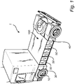
Fig. 1 , there is provided avehicle 1 in the form of a truck. Thevehicle 1 illustrated inFig. 1 comprises a pair offront wheels 10 and a pair of rear wheels 20. It should however be readily understood that thevehicle 1 may equally as well comprise a first pair of rear wheels and a second pair of rear wheels, where the first pair of wheels is positioned longitudinally in front of the second pair of rear wheels. The second pair of rear wheels may be connected to a so-called tag-axle and the first pair of rear wheels may be connected to a so-called pusher axle. - Furthermore, the
vehicle 1 comprises a plurality ofmodules 50 arranged to supply power for propelling an electric machine (not shown) of thevehicle 1. Thevehicle 1 is thus operated using at least one electric machine, which can be arranged in the form of wheel hub motors or a single electric motor connected to e.g. the pair of front wheels. Themodules 50 may thus form a plurality of vehicle batteries for supplying electrical power to the electric machine. Themodules 50 may on the other hand, as an alternative, form a plurality of hydrogen tanks comprising hydrogen fuel which is supplied to a fuel cell system that generates electric power to be supplied to a battery or directly to the electric machine. - As is further illustrated in
Fig. 1 , the vehicle comprises aframe structure 100. The frame structure comprises a frontwheel suspension arrangement 30 and a rearwheel suspension arrangement 40. The front 30 and rear 40 wheel suspension arrangements are not depicted in detail inFig. 1 but should be understood to suspend the pair offront wheels 10 and pair of rear wheels 20, respectively. Theframe structure 100 further comprises a load bearing frame arrangement 102 (seeFigs. 2 - 3 ) extending between the front 30 and rear 40 wheel suspension arrangements. Thevehicle 1 depicted inFig. 1 does hence not contain a conventional frame structure which is composed of two longitudinally extending frame rails positioned at a transversal distance from each other. Instead, theframe structure 100 comprises the loadbearing frame arrangement 102 which is positioned at a transversal center portion of thevehicle 1. Since the vehicle is propelled by electric machine(s), the vehicle does not contain a conventional propeller shaft. The loadbearing frame arrangement 102 is therefore preferably positioned in the space which, for an ICE operated vehicle, is conventionally occupied by such propeller shaft. - In order to describe the
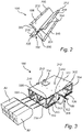
frame structure 100 in further detail, reference is now made toFig. 2 . As can be seen, theframe structure 100 comprises the above mentioned loadbearing frame arrangement 102 which is, when arranged on thevehicle 1, positioned at a transversal center portion and extending in the longitudinal direction of thevehicle 1. The loadbearing frame arrangement 102 comprises afirst member 104 and asecond member 106. The first 104 and second 106 members are extending in the longitudinal direction of thevehicle 1 between, as also indicated above, between the front 30 and rear 40 wheel suspension arrangements. Further, and as seen in a transversal cross section of the loadbearing frame arrangement 102, each of the first 104 and second 106 members comprises an extension in a diagonal direction, which are indicated by arrows numbered 202 and 204. Thediagonal extension 204 of thefirst member 104 interconnects with thediagonal extension 202 of thesecond member 106, thereby forming aconnection point 108 between the first 104 and second 106 members. The loadbearing frame arrangement 102 is hereby forming an X-shaped, longitudinally extending, load carrying beam. - Preferably, and as illustrated in
Fig. 2 , theconnection point 108 is positioned along the diagonal extension of first 104 and second 106 member, preferably at the transversal center portion of thevehicle 1. The first 104 and second 106 members may, as illustrated inFig. 2 , be formed by a respective first and second plate structure, which plate structures are connected to each other at theconnection point 108 by fasteningelements 206. Thefastening elements 206 can, for example, be formed by screw joints, bolts, rivets, welds, etc. The first 104 and second 106 members are in this configuration formed as a respective rotated V-shaped member which are fixated to each other to form the X-shaped beam. - As an alternative, the X-shaped beam can be formed in one piece in which the above-described
fastening elements 206 are superfluous. The X-shaped beam can be formed as a one piece structure by casting or extrusion, etc. A one piece X-shaped beam still comprises theconnection point 108 between the diagonally extending first and second members. - As is further illustrated in
Fig. 2 , each of the first 104 and second 106 members comprises a substantially horizontalupper support portion 208 as well as a substantially horizontallower support portion 210. The upper 208 and lower 210 support portions are arranged as support surfaces for connecting to an upper and a lower panel structure (see 112 and 116 inFig. 3 ). Theupper panel structure 112 is connected to the loadbearing frame arrangement 102 at theupper support portion 208 by means ofsuitable fastening elements 212, such as e.g. screws, bolts, rivets, welds, etc. In a similar vein, thelower panel structure 116 is connected to the loadbearing frame arrangement 102 at thelower support portion 210 by means ofsuitable fastening elements 212, such as e.g. screws, bolts, rivets, welds, etc. - Turning now to
Fig. 3 which illustrates the above-describedframe structure 100 according to an example embodiment. As described above, theframe structure 100 comprises the X-shaped loadbearing frame arrangement 102. As can be seen inFig. 3 , the upper 112 and lower 116 panel structures connected to the loadbearing frame arrangement 102 by means of thefastening elements 212. The upper 112 and lower 116 panel structures each has an extension in the transversal direction as well as in the longitudinal direction of thevehicle 1, thereby forming a "roof" and "floor" for theframe structure 100. Preferably, and as illustrated inFig. 1 , the upper 112 and lower 116 panels extend between the front 30 and rear 40 wheel suspension arrangements, thereby forming a full cover both above as well as below the X-shaped loadbearing frame arrangement 102. Theupper panel structure 112 is, together with the loadbearing frame arrangement 102, forming anupper volume 302 or cavity. In particular, an upper portion of the loadbearing frame arrangement 102 is arranged in a V-shape, which forms theupper volume 302 or cavity. In a similar vein, thelower panel structure 116 is, together with the loadbearing frame arrangement 102, forming alower volume 304 or cavity. In particular, a lower portion of the loadbearing frame arrangement 102 is arranged in a reversed V-shape, which forms thelower volume 304 or cavity. The upper 302 and lower 304 volumes/cavities are advantageously used for packaging of components, such as routing of media, cablings, etc. As is also illustrated inFig. 3 , theupper panel structure 112 comprises anaccess lid 114. Hereby, the components positioned within theupper volume 302 are accessible by an operator of the vehicle, or during maintenance. Although not depicted in the figures, the lower panel structure may also comprise a similar access lid for gaining simplified access to thelower volume 304. - The
frame structure 100 further comprises a plurality ofbrackets 110 arranged laterally outside the loadbearing frame arrangement 102. In particular, each of the brackets are connected to the loadbearing frame arrangement 102 and extends in a direction transversally away from the above-describedconnection point 108. Thebrackets 110 are positioned along the longitudinal extension of the loadbearing frame arrangement 102 at a predetermined distance from each other. Thebrackets 110 are preferably connected to the loadbearing frame arrangement 102 by means of fastening elements 308, such as screws, bolts, rivets, etc. Thebrackets 110 are further also attached/connected to the upper 112 and lower 116 panel structures by means ofbracket connectors 310 in the form of e.g. screws, bolts, rivets, etc. - The
brackets 110, together with the loadbearing frame arrangement 102, theupper panel structure 112 and thelower panel structure 116 forms acavity 320 in which themodules 50, in the following merely referred to as batteries/battery modules, can be positioned. In particular, one or more battery modules can be arranged between a pair of brackets in thecavity 320 formed therebetween. The batteries are, after insertion to thecavity 320, fixated to the frame structure in a suitable manner. By arranging the battery modules in this manner, the brackets will act as a load transferring element in case of e.g. a side collision. The load from such a side collision will thus be transferred to the loadbearing frame arrangement 102 via thebrackets 110, thereby protecting the batteries form damage. - It is to be understood that the present disclosure is not limited to the embodiments described above and illustrated in the drawings; rather, the skilled person will recognize that many changes and modifications may be made within the scope of the appended claims.
Claims (15)
- A frame structure (100) for a vehicle comprising a front wheel suspension arrangement for suspending a pair of front wheels of the vehicle, and a rear wheel suspension arrangement for suspending a pair of rear wheels of the vehicle, wherein the frame structure (100) comprises a load bearing frame arrangement (102) arranged to be positioned at a transversal center portion of the vehicle, the load bearing frame arrangement (102) comprising a first member (104) and a second member (106), each of the first and second members forming a diagonal extension as seen in a transversal cross section of the load bearing frame arrangement, wherein the diagonal first and second members extend longitudinally between the front wheel suspension arrangement and the rear wheel suspension arrangement, wherein the diagonal extension of the first member (104) interconnects with the diagonal extension of the second member (106) forming a connection point (108) between the first and second members.
- The frame structure according to claim 1, wherein the connection point is positioned along the diagonal extension of the first and second members.
- The frame structure according to any one of claims 1 or 2, wherein the connection point is arranged to be positioned at the transversal center portion of the vehicle.
- The frame structure according to any one of the preceding claims, wherein the first and second members are connected to each other by a fastening element to form the connection point.
- The frame structure according to any one of the preceding claims, wherein the diagonal extension of the first member interconnects with the diagonal extension of the second member forming an X-shaped, longitudinally extending, load carrying beam.
- The frame structure according to any one of the preceding claims, further comprising a plurality of brackets (110) connected to the load bearing frame arrangement.
- The frame structure according to claim 6, wherein each of the plurality of brackets is connected to the load bearing frame arrangement and extends transversally away from the connection point.
- The frame structure according to any one of claims 6 or 7, wherein the brackets are positioned along the longitudinal extension of the load bearing frame arrangement at a predetermined distance from each other.
- The frame structure according to any one of the preceding claims, further comprising an upper panel structure (112) fixated to a vertical upper portion of the load bearing frame arrangement.
- The frame structure according to claim 9, wherein the upper panel structure comprises an extension in the transversal and longitudinal direction of the load bearing arrangement.
- The frame structure according to any one of claims 9 or 10, wherein the upper panel structure comprises an access lid (114) positioned vertically above the connection point.
- The frame structure according to any one of claims 9-11 in combination with any one of claims 6 - 8, wherein the upper panel structure is fixated to a vertical upper portion of the plurality of brackets.
- The frame structure according to any one of the preceding claims, further comprising a lower panel structure (116) fixated to a vertical lower portion of the load bearing frame arrangement.
- A vehicle, comprising a front wheel suspension arrangement for suspending a pair of front wheels of the vehicle, and a rear wheel suspension arrangement for suspending a pair of rear wheels of the vehicle, and a frame structure according to any one of the preceding claims, wherein the frame structure extends between the front wheel suspension arrangement and the rear wheel suspension arrangement.
- The vehicle according to claim 14, wherein the vehicle comprises a electric machine for propelling the vehicle, the vehicle further comprises a plurality of vehicle batteries electrically connected to the electric machine, wherein the vehicle batteries are connected to the load bearing frame arrangement transversally outside the connection point.
Priority Applications (3)
| Application Number | Priority Date | Filing Date | Title |
|---|---|---|---|
| EP21160252.9A EP4052998B1 (en) | 2021-03-02 | 2021-03-02 | A frame structure for a vehicle |
| US17/677,023 US12208669B2 (en) | 2021-03-02 | 2022-02-22 | Frame structure for a vehicle |
| CN202210168024.2A CN114987615B (en) | 2021-03-02 | 2022-02-23 | Frame structure for vehicle |
Applications Claiming Priority (1)
| Application Number | Priority Date | Filing Date | Title |
|---|---|---|---|
| EP21160252.9A EP4052998B1 (en) | 2021-03-02 | 2021-03-02 | A frame structure for a vehicle |
Publications (3)
| Publication Number | Publication Date |
|---|---|
| EP4052998A1 true EP4052998A1 (en) | 2022-09-07 |
| EP4052998C0 EP4052998C0 (en) | 2025-05-07 |
| EP4052998B1 EP4052998B1 (en) | 2025-05-07 |
Family
ID=74856639
Family Applications (1)
| Application Number | Title | Priority Date | Filing Date |
|---|---|---|---|
| EP21160252.9A Active EP4052998B1 (en) | 2021-03-02 | 2021-03-02 | A frame structure for a vehicle |
Country Status (3)
| Country | Link |
|---|---|
| US (1) | US12208669B2 (en) |
| EP (1) | EP4052998B1 (en) |
| CN (1) | CN114987615B (en) |
Cited By (1)
| Publication number | Priority date | Publication date | Assignee | Title |
|---|---|---|---|---|
| CN116691836A (en) * | 2023-06-30 | 2023-09-05 | 三亚学院 | Box girder type frame body, frame assembly and vehicle |
Families Citing this family (9)
| Publication number | Priority date | Publication date | Assignee | Title |
|---|---|---|---|---|
| WO2020160747A1 (en) * | 2019-02-04 | 2020-08-13 | Volvo Truck Corporation | Electrically powered commercial vehicle having a battery structure |
| EP4155103B1 (en) * | 2019-04-04 | 2025-01-15 | Volvo Truck Corporation | A system and a method for installation of traction batteries for a vehicle |
| EP3925808A1 (en) * | 2020-06-16 | 2021-12-22 | Volvo Truck Corporation | Chassis arrangement for electrified heavy vehicle and electrified heavy vehicle |
| EP3925807B1 (en) | 2020-06-16 | 2024-01-24 | Volvo Truck Corporation | Battery module support arrangement |
| DE102020121828A1 (en) * | 2020-08-20 | 2022-02-24 | Man Truck & Bus Se | Motor mount and vehicle with such a motor mount |
| US12502942B1 (en) | 2021-06-29 | 2025-12-23 | Oshkosh Corporation | Vehicle with reconfigurable energy storage |
| EP4112391A1 (en) * | 2021-06-30 | 2023-01-04 | Volvo Truck Corporation | A chassis assembly for a vehicle |
| US12533937B2 (en) | 2022-06-28 | 2026-01-27 | Oshkosh Corporation | Steps and mounting for underslung battery pack |
| US20230415556A1 (en) * | 2022-06-28 | 2023-12-28 | Oshkosh Corporation | Unibody refuse vehicle |
Citations (6)
| Publication number | Priority date | Publication date | Assignee | Title |
|---|---|---|---|---|
| WO2000063060A1 (en) * | 1999-04-15 | 2000-10-26 | Scania Cv Aktiebolag (Publ) | Load carrying arrangement for a vehicle |
| GB2515535A (en) * | 2013-06-27 | 2014-12-31 | Daimler Ag | Cross member for a frame of a vehicle as well as frame for a vehicle |
| CN106184371A (en) * | 2016-08-22 | 2016-12-07 | 东莞市瑞达电瓶车科技有限公司 | Lightweight structure of a four-wheel electric vehicle frame |
| US9988086B1 (en) * | 2016-11-01 | 2018-06-05 | Eddie Adkins, Jr. | Vehicle sub-frame structure and truck incorporating same |
| EP3696054A1 (en) * | 2019-02-15 | 2020-08-19 | MAN Truck & Bus SE | Modular vehicle chassis with rear frame overhang |
| US10787200B1 (en) * | 2017-10-20 | 2020-09-29 | Extreme Trailers Llc | Suspension support for cargo carrying vehicle |
Family Cites Families (21)
| Publication number | Priority date | Publication date | Assignee | Title |
|---|---|---|---|---|
| US2846263A (en) * | 1955-07-08 | 1958-08-05 | Kaiser Aluminium Chem Corp | Vehicle |
| AT302824B (en) * | 1968-07-31 | 1972-10-25 | Schmidt Dipl Ing Karl Heinz | Vehicle frames for road or off-road trucks, in particular for crane vehicles |
| US4160558A (en) * | 1977-10-19 | 1979-07-10 | Harnischfeger Corporation | Carrier frame for mobile crane |
| AU5051879A (en) * | 1979-09-03 | 1981-03-12 | Newman, T.L. | Road-rail crane vehicle |
| US4570973A (en) * | 1984-03-21 | 1986-02-18 | Federal Motors, Inc. | Fire truck torque box aerial frame |
| US6712393B2 (en) * | 2002-02-08 | 2004-03-30 | Volvo Trucks North America, Inc. | Tubular crossmember |
| JP4024597B2 (en) * | 2002-06-11 | 2007-12-19 | 独立行政法人科学技術振興機構 | Electric vehicle body structure |
| WO2007106913A2 (en) * | 2006-03-16 | 2007-09-20 | Hendrickson International Corporation | Frame for heavy-duty vehicles |
| US9108677B2 (en) * | 2010-10-07 | 2015-08-18 | Wrt Equipment Ltd | End dump trailer |
| US9315213B2 (en) * | 2012-06-21 | 2016-04-19 | Pantero Technologies Inc. | Planar space frame for vehicle structure and housing of components |
| JP6520808B2 (en) | 2016-04-21 | 2019-05-29 | トヨタ自動車株式会社 | Vehicle battery mounting structure |
| US11097606B2 (en) * | 2016-05-26 | 2021-08-24 | Electrameccanica Vehicles Corp. | Modular rolling chassis for a vehicle |
| CN206528528U (en) | 2017-03-10 | 2017-09-29 | 重庆市馨葳机械制造有限公司 | Automobile front longitudinal beam assembly |
| JP6963867B2 (en) | 2017-04-04 | 2021-11-10 | 株式会社ソミックマネージメントホールディングス | Multipurpose platform |
| GB2565848A (en) * | 2017-08-25 | 2019-02-27 | Arrival Ltd | Vehicle, Vehicle chassis and drivetrain module |
| JP7069603B2 (en) | 2017-08-28 | 2022-05-18 | スズキ株式会社 | Body structure of electric vehicle |
| MX2022012587A (en) * | 2017-09-13 | 2022-11-09 | Wabash National Lp | Side underride guard. |
| US11040610B2 (en) * | 2019-04-19 | 2021-06-22 | Hexagon Purus North America Holdings Inc. | Electric powertrain system for heavy duty vehicles |
| EP3925807B1 (en) * | 2020-06-16 | 2024-01-24 | Volvo Truck Corporation | Battery module support arrangement |
| EP3925808A1 (en) * | 2020-06-16 | 2021-12-22 | Volvo Truck Corporation | Chassis arrangement for electrified heavy vehicle and electrified heavy vehicle |
| DE102020004026A1 (en) * | 2020-07-03 | 2020-08-27 | Daimler Ag | Traction battery holder for commercial vehicles |
-
2021
- 2021-03-02 EP EP21160252.9A patent/EP4052998B1/en active Active
-
2022
- 2022-02-22 US US17/677,023 patent/US12208669B2/en active Active
- 2022-02-23 CN CN202210168024.2A patent/CN114987615B/en active Active
Patent Citations (6)
| Publication number | Priority date | Publication date | Assignee | Title |
|---|---|---|---|---|
| WO2000063060A1 (en) * | 1999-04-15 | 2000-10-26 | Scania Cv Aktiebolag (Publ) | Load carrying arrangement for a vehicle |
| GB2515535A (en) * | 2013-06-27 | 2014-12-31 | Daimler Ag | Cross member for a frame of a vehicle as well as frame for a vehicle |
| CN106184371A (en) * | 2016-08-22 | 2016-12-07 | 东莞市瑞达电瓶车科技有限公司 | Lightweight structure of a four-wheel electric vehicle frame |
| US9988086B1 (en) * | 2016-11-01 | 2018-06-05 | Eddie Adkins, Jr. | Vehicle sub-frame structure and truck incorporating same |
| US10787200B1 (en) * | 2017-10-20 | 2020-09-29 | Extreme Trailers Llc | Suspension support for cargo carrying vehicle |
| EP3696054A1 (en) * | 2019-02-15 | 2020-08-19 | MAN Truck & Bus SE | Modular vehicle chassis with rear frame overhang |
Cited By (1)
| Publication number | Priority date | Publication date | Assignee | Title |
|---|---|---|---|---|
| CN116691836A (en) * | 2023-06-30 | 2023-09-05 | 三亚学院 | Box girder type frame body, frame assembly and vehicle |
Also Published As
| Publication number | Publication date |
|---|---|
| EP4052998C0 (en) | 2025-05-07 |
| CN114987615B (en) | 2024-10-22 |
| US12208669B2 (en) | 2025-01-28 |
| EP4052998B1 (en) | 2025-05-07 |
| CN114987615A (en) | 2022-09-02 |
| US20220281306A1 (en) | 2022-09-08 |
Similar Documents
| Publication | Publication Date | Title |
|---|---|---|
| US12208669B2 (en) | Frame structure for a vehicle | |
| US11155148B2 (en) | Integrated mounting systems for mounting electric drive components within electrified vehicles | |
| US12403794B2 (en) | Electric vehicle battery unit and battery unit installation method | |
| US11912122B2 (en) | High voltage battery pack support and isolation for electrified vehicles | |
| EP3805027B1 (en) | Electric vehicle | |
| US11794562B2 (en) | Hydrogen tank and traction battery arrangement | |
| US11548361B2 (en) | Support structures for vehicle frame mounted battery packs | |
| CN101537785B (en) | Protective housing used for galvanic cell in motor vehicle | |
| US12351012B2 (en) | Energy storage compartment | |
| US9950601B2 (en) | Vehicle with high voltage equipment arranged behind seat | |
| JP2011020625A (en) | Mounting structure for electric vehicle | |
| US10752072B2 (en) | Electrified vehicle with vibration isolator within frame and corresponding method | |
| US20240300324A1 (en) | Vehicle body lower structure | |
| KR20210017355A (en) | Battery and fuel tank arrangement structure of hybrid vehicle | |
| US10559795B1 (en) | Chassis brace for protecting traction battery | |
| US10011160B2 (en) | Vehicle | |
| US11904675B2 (en) | Support structures for vehicle underbody mounted battery packs | |
| US10000240B2 (en) | Vehicle high voltage equipment mounting for rear-end collisions | |
| US10618425B2 (en) | High voltage battery pack mounting systems for electrified vehicles | |
| CN117134059A (en) | Traction battery pack with mixed material pallet construction | |
| EP4366968A1 (en) | A suspension arrangement for an energy storage system | |
| KR102656670B1 (en) | Electric Vehicle Platform with In-Wheel Motor | |
| CN117650325A (en) | Cell stack end cap for use in traction battery packs |
Legal Events
| Date | Code | Title | Description |
|---|---|---|---|
| PUAI | Public reference made under article 153(3) epc to a published international application that has entered the european phase |
Free format text: ORIGINAL CODE: 0009012 |
|
| STAA | Information on the status of an ep patent application or granted ep patent |
Free format text: STATUS: THE APPLICATION HAS BEEN PUBLISHED |
|
| AK | Designated contracting states |
Kind code of ref document: A1 Designated state(s): AL AT BE BG CH CY CZ DE DK EE ES FI FR GB GR HR HU IE IS IT LI LT LU LV MC MK MT NL NO PL PT RO RS SE SI SK SM TR |
|
| STAA | Information on the status of an ep patent application or granted ep patent |
Free format text: STATUS: REQUEST FOR EXAMINATION WAS MADE |
|
| 17P | Request for examination filed |
Effective date: 20230223 |
|
| RBV | Designated contracting states (corrected) |
Designated state(s): AL AT BE BG CH CY CZ DE DK EE ES FI FR GB GR HR HU IE IS IT LI LT LU LV MC MK MT NL NO PL PT RO RS SE SI SK SM TR |
|
| GRAP | Despatch of communication of intention to grant a patent |
Free format text: ORIGINAL CODE: EPIDOSNIGR1 |
|
| STAA | Information on the status of an ep patent application or granted ep patent |
Free format text: STATUS: GRANT OF PATENT IS INTENDED |
|
| RIC1 | Information provided on ipc code assigned before grant |
Ipc: B60K 1/04 20190101ALN20241125BHEP Ipc: B62D 21/10 20060101ALI20241125BHEP Ipc: B62D 21/04 20060101ALI20241125BHEP Ipc: B62D 21/03 20060101AFI20241125BHEP |
|
| INTG | Intention to grant announced |
Effective date: 20241211 |
|
| GRAS | Grant fee paid |
Free format text: ORIGINAL CODE: EPIDOSNIGR3 |
|
| GRAA | (expected) grant |
Free format text: ORIGINAL CODE: 0009210 |
|
| STAA | Information on the status of an ep patent application or granted ep patent |
Free format text: STATUS: THE PATENT HAS BEEN GRANTED |
|
| AK | Designated contracting states |
Kind code of ref document: B1 Designated state(s): AL AT BE BG CH CY CZ DE DK EE ES FI FR GB GR HR HU IE IS IT LI LT LU LV MC MK MT NL NO PL PT RO RS SE SI SK SM TR |
|
| REG | Reference to a national code |
Ref country code: GB Ref legal event code: FG4D |
|
| REG | Reference to a national code |
Ref country code: CH Ref legal event code: EP |
|
| REG | Reference to a national code |
Ref country code: DE Ref legal event code: R096 Ref document number: 602021030231 Country of ref document: DE |
|
| REG | Reference to a national code |
Ref country code: IE Ref legal event code: FG4D |
|
| U01 | Request for unitary effect filed |
Effective date: 20250602 |
|
| U07 | Unitary effect registered |
Designated state(s): AT BE BG DE DK EE FI FR IT LT LU LV MT NL PT RO SE SI Effective date: 20250610 |
|
| PG25 | Lapsed in a contracting state [announced via postgrant information from national office to epo] |
Ref country code: ES Free format text: LAPSE BECAUSE OF FAILURE TO SUBMIT A TRANSLATION OF THE DESCRIPTION OR TO PAY THE FEE WITHIN THE PRESCRIBED TIME-LIMIT Effective date: 20250507 |
|
| PG25 | Lapsed in a contracting state [announced via postgrant information from national office to epo] |
Ref country code: GR Free format text: LAPSE BECAUSE OF FAILURE TO SUBMIT A TRANSLATION OF THE DESCRIPTION OR TO PAY THE FEE WITHIN THE PRESCRIBED TIME-LIMIT Effective date: 20250808 Ref country code: NO Free format text: LAPSE BECAUSE OF FAILURE TO SUBMIT A TRANSLATION OF THE DESCRIPTION OR TO PAY THE FEE WITHIN THE PRESCRIBED TIME-LIMIT Effective date: 20250807 |
|
| PG25 | Lapsed in a contracting state [announced via postgrant information from national office to epo] |
Ref country code: PL Free format text: LAPSE BECAUSE OF FAILURE TO SUBMIT A TRANSLATION OF THE DESCRIPTION OR TO PAY THE FEE WITHIN THE PRESCRIBED TIME-LIMIT Effective date: 20250507 |
|
| PG25 | Lapsed in a contracting state [announced via postgrant information from national office to epo] |
Ref country code: HR Free format text: LAPSE BECAUSE OF FAILURE TO SUBMIT A TRANSLATION OF THE DESCRIPTION OR TO PAY THE FEE WITHIN THE PRESCRIBED TIME-LIMIT Effective date: 20250507 |
|
| PG25 | Lapsed in a contracting state [announced via postgrant information from national office to epo] |
Ref country code: RS Free format text: LAPSE BECAUSE OF FAILURE TO SUBMIT A TRANSLATION OF THE DESCRIPTION OR TO PAY THE FEE WITHIN THE PRESCRIBED TIME-LIMIT Effective date: 20250807 |
|
| PG25 | Lapsed in a contracting state [announced via postgrant information from national office to epo] |
Ref country code: IS Free format text: LAPSE BECAUSE OF FAILURE TO SUBMIT A TRANSLATION OF THE DESCRIPTION OR TO PAY THE FEE WITHIN THE PRESCRIBED TIME-LIMIT Effective date: 20250907 |
|
| PG25 | Lapsed in a contracting state [announced via postgrant information from national office to epo] |
Ref country code: SM Free format text: LAPSE BECAUSE OF FAILURE TO SUBMIT A TRANSLATION OF THE DESCRIPTION OR TO PAY THE FEE WITHIN THE PRESCRIBED TIME-LIMIT Effective date: 20250507 |
|
| PG25 | Lapsed in a contracting state [announced via postgrant information from national office to epo] |
Ref country code: CZ Free format text: LAPSE BECAUSE OF FAILURE TO SUBMIT A TRANSLATION OF THE DESCRIPTION OR TO PAY THE FEE WITHIN THE PRESCRIBED TIME-LIMIT Effective date: 20250507 |
|
| PG25 | Lapsed in a contracting state [announced via postgrant information from national office to epo] |
Ref country code: SK Free format text: LAPSE BECAUSE OF FAILURE TO SUBMIT A TRANSLATION OF THE DESCRIPTION OR TO PAY THE FEE WITHIN THE PRESCRIBED TIME-LIMIT Effective date: 20250507 |
|
| PLBE | No opposition filed within time limit |
Free format text: ORIGINAL CODE: 0009261 |
|
| STAA | Information on the status of an ep patent application or granted ep patent |
Free format text: STATUS: NO OPPOSITION FILED WITHIN TIME LIMIT |
|
| REG | Reference to a national code |
Ref country code: CH Ref legal event code: L10 Free format text: ST27 STATUS EVENT CODE: U-0-0-L10-L00 (AS PROVIDED BY THE NATIONAL OFFICE) Effective date: 20260318 |
|
| 26N | No opposition filed |
Effective date: 20260210 |
|
| U20 | Renewal fee for the european patent with unitary effect paid |
Year of fee payment: 6 Effective date: 20260323 |